led turnsignal set part number:...
TRANSCRIPT

1/10I N S T A L L A T I O N I N S T R U C T I O N S
Description: LED TURNSIGNAL SET Part Number: 99000-99008-110
Applications: DL650A L2– / DL650XA L5–Installation Time: 1.5 Hours (DL650A L2 – L4)
0.5 Hours (DL650A/XA L5–)
Ref. Description QTYA LED Turnsignal 4B Lead Wire 4C Bracket 4D Nut 4E Washer 4F IC Relay 1G Earth Wire 1H 4-Way Housing (M) 1I 4-Way Housing (F) 1J Installation Instruction 1
Ref. Description(1) - Driver(2) Open end wrench
(8, 10, 12 mm)(3) Ratchet(4) Hexagon socket (3, 4 mm)(5) Socket (10 mm)(6) - Precision screwdriver(7) Pliers(8) Torque wrench(9) Service manual
Contents
ToolsRequired
(1) (2) (3)
(4) (5) (6)
(7) (8)
GENUINE SUZUKI ACCESSORIES

2/10
WARNING / CAUTION / NOTICE / NOTEPlease read this manual and follow its instructions carefully. To empha-size special information, the symbol and the words WARNING, CAU-TION, NOTICE and NOTE have special meanings. Pay particularattention to messages highlighted by these signal words:
NOTE: Indicates special information to make maintenance easier orinstructions clearer.
1. Check that the kit includes all the parts listed in the first page.2. Check each part in the kit for scratches or any form of damage.3. Park the vehicle on a level ground.4. Remove the ignition key from the switch and store it in a safe place.5. Protect any items removed or to be installed from scratches by plac-
ing them on a soft cloth first before putting them on the ground.6. Use care not to cause any damage to the body of the vehicle during
installation of the accessory.
Important
WARNINGIndicates a potential hazard that could result in death or seriousinjury.
CAUTIONIndicates a potential hazard that could result in minor or moder-ate injury.
NOTICEIndicates a potential hazard that could result in vehicle or equip-ment damage.
Precautionsfor
Installation
NOTICE
On condition that the battery voltage is low, LED turn signal lampsmay blink faster. Check that LED turn signal lamps are working nor-mally before starting engine of the bike.If LED turn signal lamps blink faster, charge the battery and make surethat all turn signal lamps are normally working.
GENUINE SUZUKI ACCESSORIES

3/10
Division of the handle switchharnessThis operation should be doneonly for DL650A L2 – L4.
1. Remove the Side cover (B) andFrame cover (C).
Remove the body cowlingassembly (A) by removing 2bolts.(Refer to DL650A service man-ual)
2. Remove the fixation bolt of theradiator and move the radiatorlower.(Refer to DL650A service man-ual)
3. Remove the LH handle switchcoupler (10 terminals : 10 lines)from the Radiator heat shield.
Disconnect the LH handleswitch coupler.
Installation
(A)(B)
(C)
(A)
NOTICEBe careful not to damage the hook of the coupler when removingthe coupler from the Radiator heat shield.
LH handle switch couplerLH handle switch coupler
Radiator heat shieldRadiator heat shield
FWDFWD
RadiatorRadiator
GENUINE SUZUKI ACCESSORIES

4/10
4. Pull out the lead wire, “sky blue 1”, “sky blue 2”, “light green”, “black”from Male/Female housing of the LH handle switch coupler.
NOTICEBe careful to distinguish the lead wire “sky blue 1” & “sky blue2”. Mark the one pair to distinguish.
How to pull out the lead wire
Coupler projection catches the hole of the terminalCoupler projection catches the hole of the terminal
Insert the precision screwdriver between the terminal and the coupler projection
Press the coupler projection down
Pull out the lead wire
LH handle switch couplerLH handle switch coupler
Sky blue 1Sky blue 1
Sky blue 2Sky blue 2
Light greenLight green
BlackBlack
LH handle switch coupler (Male) LH handle switch coupler (Female)
BlackBlack BlackBlack
Sky blue 2Sky blue 2 Sky blue 2Sky blue 2 Light greenLight greenLight greenLight greenSky blue 1Sky blue 1 Sky blue 1Sky blue 1
GENUINE SUZUKI ACCESSORIES
5/10
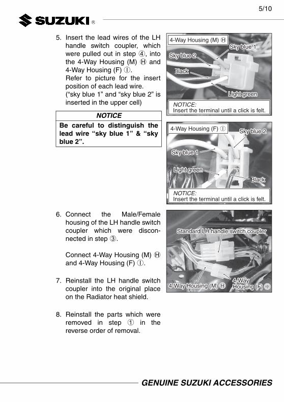
5. Insert the lead wires of the LHhandle switch coupler, whichwere pulled out in step 4, intothe 4-Way Housing (M) H and4-Way Housing (F) I.Refer to picture for the insertposition of each lead wire.(“sky blue 1” and “sky blue 2” isinserted in the upper cell)
6. Connect the Male/Femalehousing of the LH handle switchcoupler which were discon-nected in step 3.
Connect 4-Way Housing (M) Hand 4-Way Housing (F) I.
7. Reinstall the LH handle switchcoupler into the original placeon the Radiator heat shield.
8. Reinstall the parts which wereremoved in step 1 in thereverse order of removal.
NOTICEBe careful to distinguish thelead wire “sky blue 1” & “skyblue 2”.
4-Way Housing (M) HSky blue 1Sky blue 1
Sky blue 2Sky blue 2
BlackBlack
Light greenLight green
NOTICE:Insert the terminal until a click is felt.NOTICE:Insert the terminal until a click is felt.
4-Way Housing (F) I Sky blue 2Sky blue 2
Sky blue 1Sky blue 1
BlackBlack
Light greenLight green
NOTICE:Insert the terminal until a click is felt.NOTICE:Insert the terminal until a click is felt.
Standard LH handle switch couplerStandard LH handle switch coupler
4-Way Housing (M) H4-Way Housing (M) H4-Way Housing (F) I4-Way Housing (F) I
GENUINE SUZUKI ACCESSORIES

6/10
Installation of IC Relay
1. Remove the Seat and removethe standard Turnsignal relay.
2. Dismount the Turnsignal relayhousing.
3. Insert the Earth Wire G into theempty cell of the turnsignalrelay housing from the back-side.
4. Re-mount the turnsignal relayhousing.
Remove the standard Turnsignal relayRemove the standard Turnsignal relay
Turnsignal relay housingTurnsignal relay housing
NOTICEInsert the Earth Wire G until aclick is felt.
Insert the Earth Wire G into the empry cell from the backsideInsert the Earth Wire G into the empry cell from the backside
GENUINE SUZUKI ACCESSORIES

7/10
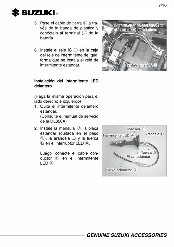
5. Pass the Earth Wire G throughthe plastic band and connect itto (–) terminal of the battery.
6. Install the IC Relay F to theTurnsignal relay housing sameway as the standard Turnsignalrelay.
Installation of front LED turnsignal
(Do the same operation for rightand left side)1. Remove the standard Front
turnsignal.(Refer to DL650A service man-ual)
2. Install the Bracket C, standardplate (removed in step 1),Washer E, and Nut D into theLED Turnsignal A.
Then, connect the Lead Wire Bto the LED turnsignal A.
Connect the Earth Wire G to (–) terminal of the batteryConnect the Earth Wire G to (–) terminal of the battery
Install the IC Relay FInstall the IC Relay F
Bracket CBracket C
LED Turnsignal ALED Turnsignal A Washer EWasher E
Standard plateStandard plate
Lead Wire BLead Wire B
Nut DNut D
GENUINE SUZUKI ACCESSORIES

8/10
3. Fix the LED turnsignal A intothe Side frame cover firmly.
NOTE: Adjust the right and leftturnsignal to be the samedirection. (90 degrees tothe ground)
4. Connect the Lead Wire B tothe vehicle harness.
GENUINE SUZUKI ACCESSORIES
9/10
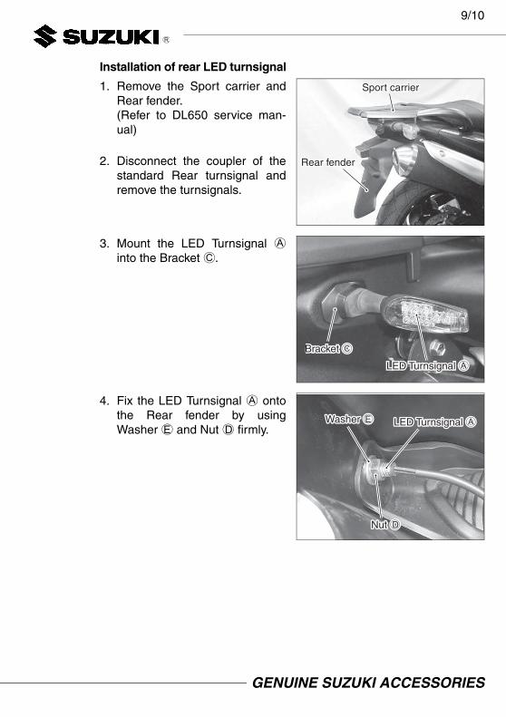
Installation of rear LED turnsignal
1. Remove the Sport carrier andRear fender.(Refer to DL650 service man-ual)
2. Disconnect the coupler of thestandard Rear turnsignal andremove the turnsignals.
3. Mount the LED Turnsignal Ainto the Bracket C.
4. Fix the LED Turnsignal A ontothe Rear fender by usingWasher E and Nut D firmly.
Sport carrierSport carrier
Rear fenderRear fender
LED Turnsignal ALED Turnsignal A
Bracket CBracket C
LED Turnsignal ALED Turnsignal AWasher EWasher E
Nut DNut D
GENUINE SUZUKI ACCESSORIES
10/10
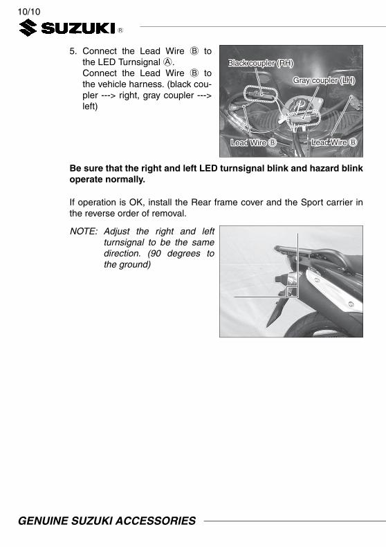
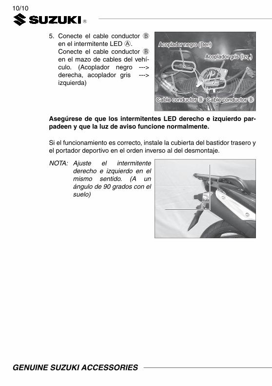
5. Connect the Lead Wire B tothe LED Turnsignal A.Connect the Lead Wire B tothe vehicle harness. (black cou-pler ---> right, gray coupler --->left)
Be sure that the right and left LED turnsignal blink and hazard blinkoperate normally.
If operation is OK, install the Rear frame cover and the Sport carrier inthe reverse order of removal.
NOTE: Adjust the right and leftturnsignal to be the samedirection. (90 degrees tothe ground)
Lead Wire BLead Wire B
Black coupler (RH)Black coupler (RH)
Gray coupler (LH)Gray coupler (LH)
Lead Wire BLead Wire B
GENUINE SUZUKI ACCESSORIES

1/10I N S T R U C T I O N S D E M O N T A G E
Description: KIT CLIGNOTANT À LED Code: 99000-99008-110
Modèle: DL650A L2– / DL650XA L5–Temps d’installation: 1,5 hr(s) (DL650A L2 – L4)
0,5 hr(s) (DL650A/XA L5–)
Réf. Description Q.téA Clignotant à LED 4B Faisceau 4C Support 4D Écrou 4E Rondelle 4F Relais Clignotant 1G Fil de masse 1H Coupleur 4-voies (M) 1I Coupleur 4-voies (F) 1J Instruction de montage 1
Réf. Description(1) Tournevis à lame(2) Clé à fourche (8, 10, 12 mm)(3) Clé à cliquet(4) Douille à six pans (3, 4 mm)(5) Douille (10 mm)(6) Tournevis de précision à
lame(7) Pinces(8) Clé dynamométrique (9) Manuel d’entretien
Contenu
Outils nécessaires
(1) (2) (3)
(4) (5) (6)
(7) (8)
GENUINE SUZUKI ACCESSORIES

2/10
AVERTISSEMENT / ATTENTION / AVIS / NOTELire attentivement ce manuel et se conformer soigneusement aux ins-tructions données. Pour souligner des informations spéciales, on utilisele symbole et les mots AVERTISSEMENT, ATTENTION, AVIS etNOTE. Lire avec soin les messages précédés par ces mots:
NOTE: Signale des informations spéciales pour faciliter l’entretien ouclarifier des instructions importantes.
1. Vérifier que le kit inclut toutes les pièces énumérées en première page.2. Vérifier que les pièces du kit ne sont pas rayées ou détériorées d’une
manière quelconque.3. Garer le véhicule sur une surface plane.4. Enlever la clé de contact du contacteur et la ranger dans un endroit sûr.5. Protéger des rayures toutes les pièces déposées ou à installer en les
plaçant sur un chiffon plutôt qu’à même le sol.6. Éviter d’endommager le véhicule pendant l’installation de l’acces-
soire.
Important
AVERTISSEMENTIndique un danger potentiel pouvant résulter en blessures gravesou mortelles.
ATTENTIONIndique un danger potentiel pouvant résulter en blessures légè-res ou modérées.
AVISIndique un danger potentiel pouvant résulter en détérioration duvéhicule ou des équipements.
Précautionsà
l’installation
AVIS
Quand la tension de la batterie est faible, les clignotants à LED ris-quent de clignoter plus rapidement. Vérifier que les clignotants à LEDfonctionnent normalement avant de mettre la moto en marche.Si les clignotants à LED clignotent plus rapidement, recharger la bat-terie et vérifier que tous les clignotants fonctionnent normalement.route.
GENUINE SUZUKI ACCESSORIES
3/10
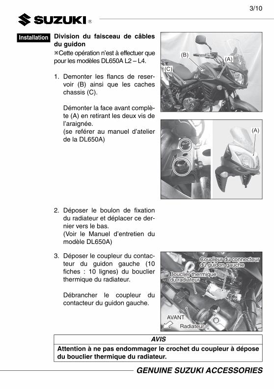
Division du faisceau de câblesdu guidonCette opération n’est à effectuer quepour les modèles DL650A L2 – L4.
1. Demonter les flancs de reser-voir (B) ainsi que les cacheschassis (C).
Démonter la face avant complè-te (A) en retirant les deux vis del’araignée.(se reférer au manuel d’atelierde la DL650A)
2. Déposer le boulon de fixationdu radiateur et déplacer ce der-nier vers le bas.(Voir le Manuel d’entretien dumodèle DL650A)
3. Déposer le coupleur du contac-teur du guidon gauche (10fiches : 10 lignes) du bouclierthermique du radiateur.
Débrancher le coupleur ducontacteur du guidon gauche.
Installation
(A)(B)
(C)
(A)
AVISAttention à ne pas endommager le crochet du coupleur à déposedu bouclier thermique du radiateur.
Coupleur du connecteur du guidon gaucheCoupleur du connecteur du guidon gauche
Bouclier thermique du radiateur Bouclier thermique du radiateur
AVANTAVANT
RadiateurRadiateur
GENUINE SUZUKI ACCESSORIES

4/10
4. Débrancher les cosses “bleu ciel 1”, “bleu ciel 2”, “vert clair” et “noir”du boîtier mâle/femelle du coupleur du contacteur du guidon gauche.
AVISPrendre soin de bien repérer les conducteurs “bleu ciel 1” et“bleu ciel 2”. Les marquer pour bien les distinguer.
Pour débrancher les cosses
La partie en saillie du coupleur s’engage dans le trou du contactLa partie en saillie du coupleur s’engage dans le trou du contact
Insérer le tournevis de précision entre le contact et la saillie du coupleur
Appuyer sur la partie en saillie du coupleur
Enlever la cosse
Coupleur du contacteur du guidon gaucheCoupleur du contacteur du guidon gauche
Bleu ciel 1Bleu ciel 1
Bleu ciel 2Bleu ciel 2
Vert clairVert clair
Noir Noir
Coupleur du contacteur du guidon gauche (Mâle)
Coupleur du contacteur du guidon gauche (Femelle)
NoirNoir NoirNoir
Bleu ciel 2Bleu ciel 2 Bleu ciel 2Bleu ciel 2 Vert clairVert clairVert clairVert clairBleu ciel 1Bleu ciel 1 Bleu ciel 1Bleu ciel 1
GENUINE SUZUKI ACCESSORIES

5/10
5. Insérer les cosses du coupleurdu contacteur du guidon gau-che débranchés à l’étape 4dans le boîtier 4-voies (M) H etle boîtier 4-voies (F) I. Voir sur la figure la positiond’insertion de chacune des cos-ses.(“bleu ciel 1” et “bleu ciel 2”s’insèrent dans la cellule supé-rieure.)
6. Rebrancher le boîtier Mâle/Femelle du coupleur du contac-teur du guidon gauche qui a étédébranché à l’étape 3.
Raccorder le boîtier 4-voies (M)H et le boîtier 4-voies (F) I.
7. Reposer le coupleur du contac-teur du guidon gauche dans saposition d’origine sur le bouclierthermique du radiateur.
8. Reposer les pièces déposées àl’étape 1 en procédant enordre inverse de leur dépose.
AVISPrendre soin à ne pas confon-dre les cosses “bleu ciel 1” et“bleu ciel 2”.
Coupleur 4-voies (M) H
Bleu ciel 1Bleu ciel 1Bleu ciel 2Bleu ciel 2
Noir Noir
Vert clairVert clair
AVIS:Insérer le contact jusqu’au clic.AVIS:Insérer le contact jusqu’au clic.
Bleu ciel 2Bleu ciel 2
Bleu ciel 1Bleu ciel 1
Noir Noir
Vert clairVert clair
AVIS:Insérer le contact jusqu’au clic.AVIS:Insérer le contact jusqu’au clic.
Coupleur 4-voies (F) I
Coupleur du contacteur du guidon gauche standard Coupleur du contacteur du guidon gauche standard
Coupleur 4-voies (M) HCoupleur 4-voies (M) HCoupleur4-voies (F) ICoupleur4-voies (F) I
GENUINE SUZUKI ACCESSORIES

6/10
Installation du relais clignotant
1. Déposer la selle et le relais cli-gnotant standard.
2. Démonter le coupleur du relaisclignotant.
3. Insérer le fil de masse G dansla cellule vide du boîtier durelais du clignotant en procé-dant depuis le dos du boîtier.
4. Réassembler le boîtier du relaisdu clignotant.
Déposer le relais clignotant standardDéposer le relais clignotant standard
Coupleur du relais clignotantCoupleur du relais clignotant
AVISInsérer le fil de masse G
jusqu’au clic.
Insérer le fil de masse G dans la cellule vide du boîtier du relais du clignotant en procédant depuis le dos du boîtier
Insérer le fil de masse G dans la cellule vide du boîtier du relais du clignotant en procédant depuis le dos du boîtier
GENUINE SUZUKI ACCESSORIES

7/10
5. Faire passer le fil de masse Gdans le bandeau en plastique etle raccorder au plot (–) de labatterie.
6. Monter le relais clignotant Fsur le boîtier du relais du cligno-tant comme l’était le relais duclignotant standard.
Installation du clignotant avant àLED
(Procéder aux mêmes opérationsà droite et à gauche.)1. Déposer le clignotant avant
standard. (Voir le Manuel d’entretien dumodèle DL650A)
2. Monter le support C, la plaquestandard (déposée à l’étape1), la rondelle E et l’écrou Dsur le clignotant à LED A.
Raccorder ensuite le faisceauB au clignotant à LED A.
Raccorder le fil de masse G au plot (–) de la batterieRaccorder le fil de masse G au plot (–) de la batterie
Monter le relais clignotant FMonter le relais clignotant F
Rondelle ERondelle E
Support CSupport C
Clignotant à LED AClignotant à LED A
Écrou DÉcrou DPlaque standard Plaque standard
Faisceau BFaisceau B
GENUINE SUZUKI ACCESSORIES

8/10
3. Fixer soigneusement le cligno-tant à LED A au couvercle decarénage latéral.
NOTE: Régler les clignotants droitet gauche selon le mêmeangle. (à 90 degrés parrapport au sol)
4. Raccorder le faisceau B aufaisceau de câbles du véhicule.
GENUINE SUZUKI ACCESSORIES

9/10
Installation du clignotant à LEDarrière
1. Déposer le porte-bagages et legarde-boue arrière.(Voir le Manuel d’entretien dumodèle DL650)
2. Débrancher le coupleur des cli-gnotants arrière standards etdéposer les clignotants.
3. Monter le clignotant à LED Asur le support C.
4. Fixer soigneusement le cligno-tant à LED A au garde-bouearrière à l’aide d’une rondelleE et d’un écrou D.
Porte-bagagesPorte-bagages
Garde-boue arrière Garde-boue arrière
Clignotant à LED AClignotant à LED A
Support CSupport C
Rondelle ERondelle E Clignotant à LED AClignotant à LED A
Écrou DÉcrou D
GENUINE SUZUKI ACCESSORIES

10/10
5. Raccorder le faisceau B au cli-gnotant à LED A.Raccorder le faisceau B aufaisceau de câbles du véhicule.(coupleur noir ---> à droite, cou-pleur gris ---> à gauche)
Vérifier que les clignotants à LED droit et gauche clignotent et queles feux de détresse fonctionnent normalement.
Si tout est normal, reposer le couvercle du cadre arrière et le porte-bagages en procédant en ordre inverse de la dépose.
NOTE: Régler les clignotants droitet gauche selon le mêmeangle. (À 90 degrés parrapport au sol.)
Coupleur noir (RH)Coupleur noir (RH)
Coupleur gris (LH)Coupleur gris (LH)
Faisceau BFaisceau B Faisceau BFaisceau B
GENUINE SUZUKI ACCESSORIES

1/10M O N T A G E A N L E I T U N G
Beschreibung: LED-BLINKLEUCHTENSATZ Teil-Nr.: 99000-99008-110
Verwendungen: DL650A L2– / DL650XA L5–Montagezeit: 1,5 hr(s) (DL650A L2 – L4)
0,5 hr(s) (DL650A/XA L5–)
Nr. Beschreibung StckA LED-Blinkleuchte 4B Zuleitungskabel 4C Halterung 4D Mutter 4E Scheibe 4F IC-Relais 1G Massekabel 1H Vierwegegehäuse (M) 1I Vierwegegehäuse (W) 1J Montageanleitung 1
Nr. Beschreibung(1) Schlitzschraubendreher(2) Gabelschlüssel
(8, 10, 12 mm)(3) Ratsche(4) Steckschlüsseleinsatz mit
Sechskant (3, 4 mm)(5) Nuss (10 mm)(6) Präzisionsschlitzschraubendre-
her(7) Zange(8) Drehmomentschlüssel(9) Wartungsanleitung
Inhalt
Notwendigewerkzeuge
(1) (2) (3)
(4) (5) (6)
(7) (8)
GENUINE SUZUKI ACCESSORIES

2/10
WARNUNG / VORSICHT / HINWEIS / ANMERKUNGLesen Sie bitte dieses Handbuch und befolgen Sie die darin enthaltenenAnweisungen genau. Das Symbol und die Schlüsselwörter WARNUNG,VORSICHT, HINWEIS sowie ANMERKUNG werden zur Betonung speziellerInformationen verwendet. Beachten Sie insbesondere Informationen, diedurch die folgenden Schlüsselwörter gekennzeichnet sind:
ANMERKUNG: Kennzeichnet Informationen, die Wartungsarbeiten erleich-tern bzw. Anweisungen verdeutlichen sollen.
1. Prüfen, ob der Satz alle auf der ersten Seite aufgeführten Teile enthält.2. Jedes Teil im Satz auf Kratzer und Beschädigung überprüfen.3. Das Fahrzeug auf ebenem Untergrund parken.4. Den Zündschlüssel abziehen und an sicherer Stelle aufbewahren.5. Abgenommene oder zu montierende Teile nicht einfach auf den
Boden, sondern auf einen weichen Lappen legen, damit sie nicht ver-kratzt werden.
6. Darauf achten, dass die Fahrzeugkarosserie bei der Montage desZubehörs nicht beschädigt wird.
Wichtig
WARNUNGWeist auf eine mögliche Gefahr hin, die tödlich ausgehen oderschwere Verletzungen verursachen kann.
VORSICHTWeist auf eine mögliche Gefahr hin, die leichte bis mittelschwereVerletzungen verursachen kann.
HINWEISWeist auf eine mögliche Gefahr hin, die zu Fahrzeug- und Ausrü-stungsschäden führen kann.
Wichtige hinweise zur
montage
HINWEIS
Bei niedriger Batteriespannung kann es zu schnellerem Blinken derLED-Blinkleuchten kommen. Vergewissern Sie sich, dass die LED-Blinkleuchten normal funktionieren, bevor Sie den Motordes Kraftradsstarten.Wenn die LED-Blinkleuchten schneller blinken, laden Sie die Batterie,und stellen Sie sicher, dass alle Blinkleuchten normal funktionieren.
GENUINE SUZUKI ACCESSORIES
3/10
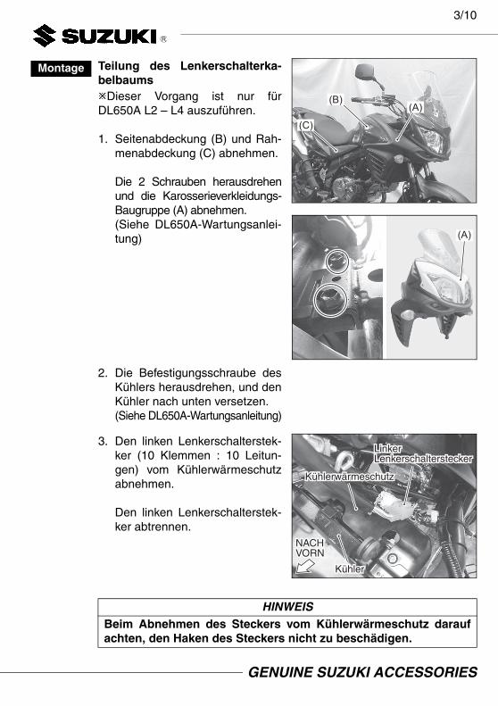
Teilung des Lenkerschalterka-belbaumsDieser Vorgang ist nur fürDL650A L2 – L4 auszuführen.
1. Seitenabdeckung (B) und Rah-menabdeckung (C) abnehmen.
Die 2 Schrauben herausdrehenund die Karosserieverkleidungs-Baugruppe (A) abnehmen.(Siehe DL650A-Wartungsanlei-tung)
2. Die Befestigungsschraube desKühlers herausdrehen, und denKühler nach unten versetzen.(Siehe DL650A-Wartungsanleitung)
3. Den linken Lenkerschalterstek-ker (10 Klemmen : 10 Leitun-gen) vom Kühlerwärmeschutzabnehmen.
Den linken Lenkerschalterstek-ker abtrennen.
Montage
(A)(B)
(C)
(A)
HINWEISBeim Abnehmen des Steckers vom Kühlerwärmeschutz daraufachten, den Haken des Steckers nicht zu beschädigen.
Linker LenkerschaltersteckerLinker Lenkerschalterstecker
KühlerwärmeschutzKühlerwärmeschutz
NACH VORNNACH VORN
KühlerKühler
GENUINE SUZUKI ACCESSORIES

4/10
4. Die Zuleitungskabel “himmelblau 1”, “himmelblau 2”, “hellgrün” und“schwarz” aus dem männlichen/weiblichen Gehäuse des linken Len-kerschaltersteckers ziehen.
HINWEISDarauf achten, die Zuleitungskabel “himmelblau 1” und “himmelblau2” zu unterscheiden. Ein Paar zur Unterscheidung markieren.
Herausziehen des Zuleitungskabels
Steckervorsprung greift in Öffnung der KlemmeSteckervorsprung greift in Öffnung der Klemme
Den Präzisionsschraubendreher zwischen Klemme und Steckervorsprung einsetzen
Den Steckervorsprung niederdrücken
Das Zuleitungskabel herausziehen
Linker LenkerschaltersteckerLinker Lenkerschalterstecker
Himmelblau 1Himmelblau 1
Himmelblau 2Himmelblau 2
HellgrünHellgrün
SchwarzSchwarz
Linker Lenkerschalterstecker (Pin Männlich)
Linker Lenkerschalterstecker (Pin Weiblich)
SchwarzSchwarz SchwarzSchwarz
Himmelblau 2Himmelblau 2 Himmelblau 2Himmelblau 2 HellgrünHellgrünHellgrünHellgrünHimmelblau 1Himmelblau 1 Himmelblau 1Himmelblau 1
GENUINE SUZUKI ACCESSORIES

5/10
5. Die Zuleitungskabel des linkenLenkerschaltersteckers, die inSchritt 4 herausgezogen wur-den, in das Vierwegegehäuse(M) H und das Vierwegege-häuse (W) I einsetzen.Bezüglich der Einsetzpositionjedes Zuleitungskabels sieheBild. (“himmelblau 1” und “him-melblau 2” werden in der obe-ren Zelle eingesetzt)
6. Männliches/weibliches Gehäusedes linken Lenkerschalterstek-kers, die in Schritt 3 abgetrenntwurden, anschließen.
Das Vierwegegehäuse (M) Hund das Vierwegegehäuse (W)I anschließen.
7. Den linken Lenkerschalterstek-ker wieder am Kühlerwärme-schutz an ursprünglicher Stelleanbringen.
8. Die Teile, die in Schritt 1 abge-nommen wurden, in der umge-kehrten Reihenfolge derAusbauschritte wieder anbringen.
HINWEISDarauf achten, die Zuleitungska-bel “himmelblau 1” und “him-melblau 2” zu unterscheiden.
Vierwegegehäuse (M) H
Himmelblau 1Himmelblau 1Himmelblau 2Himmelblau 2
SchwarzSchwarz
HellgrünHellgrün
HINWEIS: Einschieben, bis ein Klicken vernommen wird.HINWEIS: Einschieben, bis ein Klicken vernommen wird.
Vierwegegehäuse (W) IHimmelblau 2Himmelblau 2
Himmelblau 1Himmelblau 1
SchwarzSchwarz
HellgrünHellgrün
HINWEIS: Einschieben, bis ein Klicken vernommen wird.HINWEIS: Einschieben, bis ein Klicken vernommen wird.
Linker Standard-LenkerschaltersteckerLinker Standard-Lenkerschalterstecker
Vierwegegehäuse (M) HVierwegegehäuse (M) H
Vierwegegehäuse (W) IVierwegegehäuse (W) I
GENUINE SUZUKI ACCESSORIES

6/10
Einbau des IC-Relais
1. Zunächst den Sitz, dann dasStandard-Blinkleuchtenrelaisabnehmen.
2. Das Blinkleuchtenrelaisgehäu-se demontieren.
3. Das Massekabel G von derRückseite in die leere Zelle desBlinkleuchtenrelaisgehäuseseinsetzen.
4. Das Blinkleuchtenrelaisgehäu-se wieder montieren.
Das Standard-Blinkleuchtenrelais abnehmenDas Standard-Blinkleuchtenrelais abnehmen
BlinkleuchtenrelaisgehäuseBlinkleuchtenrelaisgehäuse
HINWEISDas Massekabel G einschie-ben, bis ein Klicken vernom-men wird.
Das Massekabel G von der Rückseite in die leere Zelle einsetzenDas Massekabel G von der Rückseite in die leere Zelle einsetzen
GENUINE SUZUKI ACCESSORIES

7/10
5. Das Massekabel G durch dasPlastikband führen und an denMinuspol (–) der Batterieanschließen.
6. Das IC-Relais F so am Blink-leuchtenrelaisgehäuse anbrin-gen, wie das Standard-Blinkleuchtenrelais angebrachtwar.
Einbau der vorderen LED-Blink-leuchte
(Für rechte und linke Seite geltendie selben Arbeitsschritte)1. Die vordere Standard-Blink-
leuchte abnehmen. (Siehe DL650A-Wartungsanleitung)
2. Halterung C, Standardplatte (inSchritt 1 abgenommen),Scheibe E und Mutter D an derLED-Blinkleuchte A anbringen.
Dann das Zuleitungskabel Ban die LED-Blinkleuchte A
anschließen.
Das Massekabel G an den Minuspol (–) der Batterie anschließenDas Massekabel G an den Minuspol (–) der Batterie anschließen
Das IC-Relais F anbringenDas IC-Relais F anbringen
Halterung CHalterung C
LED-Blinkleuchte ALED-Blinkleuchte A Scheibe EScheibe E
StandardplatteStandardplatte
Zuleitungskabel BZuleitungskabel B
Mutter DMutter D
GENUINE SUZUKI ACCESSORIES

8/10
3. Die LED-Blinkleuchte A in derSeitenrahmenabdeckunganbringen und verschrauben.
ANMERKUNG: Rechte und linkeBlinkleuchte gleichausrichten. (90 Gradzum Boden)
4. Das Zuleitungskabel B an denFahrzeugkabelbaum anschlie-ßen.
GENUINE SUZUKI ACCESSORIES

9/10
Einbau der hinteren LED-Blink-leuchte
1. Sportträger und Hinterradkotflü-gel abnehmen.(Siehe DL650-Wartungsanleitung)
2. Den hinteren Standard-Blink-leuchtenstecker abtrennen, unddie Blinkleuchten abnehmen.
3. Die LED-Blinkleuchte A in dieHalterung C setzen.
4. Die LED-Blinkleuchte A mit-hilfe der Scheibe E und derMutter D sicher am Hinterrad-kotflügel befestigen.
SportträgerSportträger
HinterradkotflügelHinterradkotflügel
LED-Blinkleuchte ALED-Blinkleuchte A
Halterung CHalterung C
LED-Blinkleuchte ALED-Blinkleuchte AScheibe EScheibe E
Mutter DMutter D
GENUINE SUZUKI ACCESSORIES

10/10
5. Das Zuleitungskabel B an dieLED-Blinkleuchte A anschließen.Das Zuleitungskabel B an denFahrzeugkabelbaum anschlie-ßen. (schwarzer Stekker --->rechts, grauer Stecker --->links)
Sicherstellen, dass Blink- und Warnblinkbetrieb der rechten undlinken LED-Blinkleuchte in Ordnung sind.
Wenn der Betrieb in Ordnung ist, hintere Rahmenabdeckung und Sport-träger in der umgekehrten Reihenfolge des Abnehmens anbringen.
ANMERKUNG: Rechte und linkeBlinkleuchte gleichausrichten. (90 Gradzum Boden)
Zuleitungskabel BZuleitungskabel B
Schwarzer Stecker (rechts)Schwarzer Stecker (rechts)
Grauer Stecker (links)Grauer Stecker (links)
Zuleitungskabel BZuleitungskabel B
GENUINE SUZUKI ACCESSORIES

1/10 I S T R U Z I O N I D I M O N T A G G I O
Descrizione: SET INDICATORI DI DIREZIONE A LED Codice: 99000-99008-110
Applicabilità: DL650A L2– / DL650XA L5–Tempi installazione: 1,5 ora (DL650A L2 – L4)
0,5 ora (DL650A/XA L5–)
Rif. Descrizione Q.taA Indicatore di direzione a LED 4B Cablaggio 4C Staffa 4D Dado 4E Rondella 4F Relé 1G Filo di terra 1H Alloggiamento connettore a 4 vie (M) 1I Connettore a 4 vie (F) 1J Instruzioni di montaggio 1
Rif. Descrizione(1) Cacciavite -(2) Chiave fissa (8, 10, 12 mm)(3) Chiave a cricchetto(4) Chiave esagonale (3, 4 mm)(5) Brugola (10 mm)(6) Cacciavite - di precisione(7) Pinze(8) Chiave torsiometrica(9) Manuale di servizio
Contenuto
Attrezzi necessari
(1) (2) (3)
(4) (5) (6)
(7) (8)
GENUINE SUZUKI ACCESSORIES

2/10
ATTENZIONE / AVVERTENZA / AVVISO / NOTALeggere questo manuale e seguire con attenzione le sue istruzioni. Ilsimbolo e le parole ATTENZIONE, AVVERTENZA, AVVISO e NOTAenfatizzano la presenza di importanti informazioni. Fare attenzione parti-colare ai messaggi evidenziati da queste parole:
NOTA: Indica informazioni speciali per rendere più facile la manuten-zione oppure per chiarire le istruzioni date.
1. Controllare che il kit contenga tutte le parti elencate nella primapagina.
2. Controllare che nessuna parte del kit abbia graffi o danni.3. Parcheggiare il veicolo in un punto in piano.4. Rimuovere la chiave di accensione dall’interruttore e conservarla in
un luogo sicuro.5. Proteggere ogni elemento tolto o da installare da graffi mettendolo su
di un panno soffice steso a terra.6. Fare attenzione a non danneggiare la scocca del veicolo durante
l’installazione dell’accessorio.
Importante
ATTENZIONE
Indica un pericolo che può portare alla morte o ferimenti gravi.
AVVERTENZA
Indica un pericolo che può portare a ferimenti lievi o moderati.
AVVISOIndica un pericolo che può portare a danni al veicolo o altreattrezzature.
Precauzioni per
l’installazione
AVVISO
Se il voltaggio di batteria è basso, gli indicatori di direzione a LEDpotrebbero lampeggiare più rapidamente. Prima di avviare il motoredella motocicletta, controllare che gli indicatori di direzione a LED fun-zionino regolarmente.Se gli indicatori di direzione a LED lampeggiano più rapidamente, cari-care la batteria, e quindi controllare se tutti gli indicatori di direzionefunzionano normalmente.
GENUINE SUZUKI ACCESSORIES

3/10
Divisione del cablaggiodell’interruttore sul manubrioQuesta operazione deve essere fattasolo per il modello DL650A L2 – L4.
1. Rimuovere la copertura laterale(B) e il paratelaio (C).
Rimuovere la carena laterale (A)svitandone i 2 bulloni relativi.(fare riferimento al manuale ser-vice)
2. Rimuovere il bullone di fissaggio delradiatore e abbassare il radiatore.(Consultare il manuale dei serviziodelle DL650A)
3. Rimuovere l’accoppiatoredell’interruttore sul manubriosinistro (10 terminali : 10 righe)dallo scudo termico del radia-tore.
Scollegare l’accoppiatoredell’interruttore sul manubriosinistro.
Installazione
(A)(B)
(C)
(A)
AVVISONel rimuovere l’accoppiatore dallo scudo termico, fare attenzionea non danneggiare il gancio dell’accoppiatore.
Accoppiatore dell’interruttore del manubrio sinistroAccoppiatore dell’interruttore del manubrio sinistro
Scudo termico radiatoreScudo termico radiatore
AVANTIAVANTI
RadiatoreRadiatore
GENUINE SUZUKI ACCESSORIES

4/10
4. Togliere il fili “azzurro 1”, “azzurro 2”, “verde chiaro”, “nero” dall’allog-giamento maschio/femmina dell’accoppiatore dell’interruttore delmanubrio sinistro.
AVVISOFare attenzione a non confondere i fili “azzurro 1” ed “azzurro 2”.Segnare i due fili per poterli distinguere.
Come tirare il filo
La proiezione dell’accoppiatore entra nel foro del terminaleLa proiezione dell’accoppiatore entra nel foro del terminale
Inserire il cacciavite di precisione fra il terminale e la proiezione dell’accoppiatore
Premere la proiezione dell’accoppiatore verso il basso
Togliere il filo
Accoppiatore dell’interruttore del manubrio sinistroAccoppiatore dell’interruttore del manubrio sinistro
Azzurro 1Azzurro 1
Azzurro 2Azzurro 2
Verde chiaroVerde chiaro
NeroNero
Accoppiatore dell’interruttore del manubrio sinistro (maschio)
Accoppiatore dell’interruttore del manubrio sinistro (femmina)
NeroNero NeroNero
Azzurro 2Azzurro 2 Azzurro 2Azzurro 2 Verde chiaroVerde chiaroVerde chiaroVerde chiaroAzzurro 1Azzurro 1 Azzurro 1Azzurro 1
GENUINE SUZUKI ACCESSORIES

5/10
5. Inserire i fili dell’accoppiatoredell’interruttore del manubrio sini-stro, tolti nella fase 4, nell’allog-giamento a 4 vie (M) H enell’alloggiamento a 4 vie (F) I.Per quanto riguarda la posi-zione di ciascun filo, vederel’immagine. (“azzurro 1” e“azzurro 2” vengono inseritinella cella superiore)
6. Collegare l’alloggiamentomaschio/femmina dell’accoppia-tore dell’interruttore del manubriosinistro scollegato nella fase 3.
Collegare l’alloggiamento a 4vie (M) H e quello (F) I.
7. Reinstallare l’accoppiatoredell’interruttore del manubrio sini-stro nel suo posto originale sulloscudo termico del radiatore.
8. Reinstallare le parti rimossenella fase 1 in ordine inverso aquello di rimozione.
AVVISOFare attenzione a non confon-dere i fili “azzurro 1” ed“azzurro 2”.
Alloggiamento a 4 vie (M) H
Azzurro 1Azzurro 1Azzurro 2Azzurro 2
NeroNero
Verde chiaroVerde chiaro
AVVISO:Inserire il terminale fino a sentire un clic.AVVISO:Inserire il terminale fino a sentire un clic.
Alloggiamento a 4 vie (F) I
Azzurro 2Azzurro 2
Azzurro 1Azzurro 1
NeroNero
Verde chiaroVerde chiaro
AVVISO:Inserire il terminale fino a sentire un clic.AVVISO:Inserire il terminale fino a sentire un clic.
Accoppiatore standard interruttore del manubrio sinistroAccoppiatore standard interruttore del manubrio sinistro
Alloggiamento a 4 vie (M) HAlloggiamento a 4 vie (M) H
Alloggiamento a 4 vie (F) IAlloggiamento a 4 vie (F) I
GENUINE SUZUKI ACCESSORIES
6/10
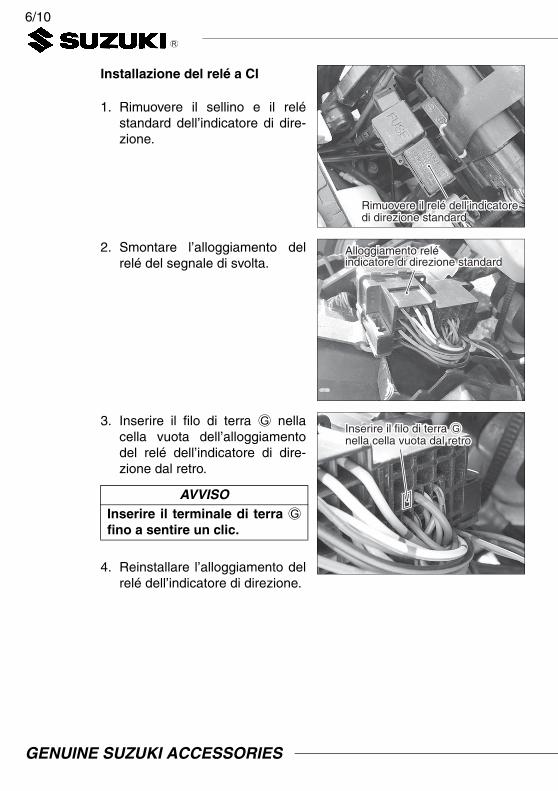
Installazione del relé a CI
1. Rimuovere il sellino e il reléstandard dell’indicatore di dire-zione.
2. Smontare l’alloggiamento delrelé del segnale di svolta.
3. Inserire il filo di terra G nellacella vuota dell’alloggiamentodel relé dell’indicatore di dire-zione dal retro.
4. Reinstallare l’alloggiamento delrelé dell’indicatore di direzione.
Rimuovere il relé dell’indicatore di direzione standardRimuovere il relé dell’indicatore di direzione standard
Alloggiamento relé indicatore di direzione standardAlloggiamento relé indicatore di direzione standard
AVVISOInserire il terminale di terra Gfino a sentire un clic.
Inserire il filo di terra G nella cella vuota dal retroInserire il filo di terra G nella cella vuota dal retro
GENUINE SUZUKI ACCESSORIES

7/10
5. Far passare il filo di terra Gattraverso la fascetta in plasticae collegarla al terminale (–) dellabatteria.
6. Installare il relé a CI F
nell’alloggiamento del relédell’indicatore di direzionecome fatto per il relé dell’indica-tore di direzione standard.
Installazione dell’indicatore di dire-zione a LED anteriore
(Fare la stessa operazione adestra e sinistra)1. Rimuovere il relé dell’indicatore
di direzione standard anteriore.(Consultare il manuale di servi-zio delle DL650A)
2. Installare la staffa C, la piastrastandard (rimossa nella fase1), la rondella E ed il dado Dnell’indicatore di direzione aLED A.
Collegare poi il filo B all’indica-tore di direzione a LED A.
Collegare il filo di terra G al terminale (–) della batteriaCollegare il filo di terra G al terminale (–) della batteria
Installare il relé a CI FInstallare il relé a CI F
Staffa CStaffa CRondella ERondella E
Piastra standardPiastra standard
Filo BFilo B
Dado DDado D
Indicatore di direzione a LED AIndicatore di direzione a LED A
GENUINE SUZUKI ACCESSORIES
8/10
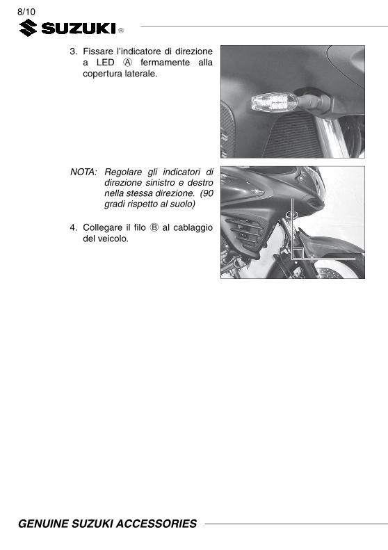
3. Fissare l’indicatore di direzionea LED A fermamente allacopertura laterale.
NOTA: Regolare gli indicatori didirezione sinistro e destronella stessa direzione. (90gradi rispetto al suolo)
4. Collegare il filo B al cablaggiodel veicolo.
GENUINE SUZUKI ACCESSORIES

9/10
Installazione dell’indicatore didirezione a LED posteriore
1. Rimuovere il portapacchi spor-tivo ed il parafango posteriore.(Consultare il manuale di servi-zio delle DL650)
2. Scollegare l’accoppiatoredell’indicatore di direzioneposteriore standard e rimuo-vere gli indicatori di direzione.
3. Fissare l’indicatore di direzioneA alla staffa C.
4. Fissare salldamente l’indicatoredi direzione a LED A al para-fango posteriore con la rondellaE ed il dado D.
Portapacchi sportivoPortapacchi sportivo
Parafango posterioreParafango posteriore
Indicatore di direzione a LED AIndicatore di direzione a LED A
Staffa CStaffa C
Indicatore di direzione a LED AIndicatore di direzione a LED ARondella ERondella E
Dado DDado D
GENUINE SUZUKI ACCESSORIES

10/10
5. Collegare il filo B all’indicatoredi direzione a LED A.Collegare il filo B al cablaggiodel veicolo. (accoppiatore nero---> destra, accoppiatore grigio---> sinistra)
Controllare che gli indicatori di direzione a LED sinistro e destrolampeggino e la luce di emergenza funzionino normalmente.
Se funzionano bene, installare la copertura del telaio posteriore e il por-tapacchi sportivo in ordine inverso a quello di rimozione.
NOTA: Regolare gli indicatori didirezione sinistro e destronella stessa direzione. (90gradi rispetto al suolo)
Filo BFilo B
Accoppiatore nero (D)Accoppiatore nero (D)
Accoppiatore grigio (S)Accoppiatore grigio (S)
Filo BFilo B
GENUINE SUZUKI ACCESSORIES

1/10I N S T R U C C I O N E S P A R A E L M O N T A J E
Descripción: JUEGO DE INTERMITENTES LED N°de de parte: 99000-99008-110
Aplicación: DL650A L2– / DL650XA L5–Tiempo de montaje: 1,5 hr(s) (DL650A L2 – L4)
0,5 hr(s) (DL650A/XA L5–)
Ref. Descripción Cant.A Intermitente LED 4B Cable conductor 4C Ménsula 4D Tuerca 4E Arandela 4F Relé IC 1G Cable de tierra 1H Caja de 4 vías (Macho) 1I Caja de 4 vías (Hembra) 1J Instrucciones para el montaje 1
Ref. Descripción(1) Destornillador -(2) Llave de bocas
(8, 10, 12 mm)(3) Trinquete(4) Llave de vaso hexagonal
(3, 4 mm)(5) Llave de vaso (10 mm)(6) Destornillador de precisión -(7) Alicates(8) Llave dinamométrica(9) Manual de servicio
Contenido
Herramientasnecesarias
(1) (2) (3)
(4) (5) (6)
(7) (8)
GENUINE SUZUKI ACCESSORIES
2/10
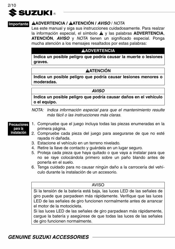
ADVERTENCIA / ATENCIÓN / AVISO / NOTALea este manual y siga sus instrucciones cuidadosamente. Para realzarla información especial, el símbolo y las palabras ADVERTENCIA,ATENCIÓN, AVISO y NOTA tienen un significado especial. Pongamucha atención a los mensajes resaltados por estas palabras:
NOTA: Indica información especial para que el mantenimiento resultemás fácil o las instrucciones más claras.
1. Compruebe que el juego incluya todas las piezas enumeradas en laprimera página.
2. Compruebe cada pieza del juego para asegurarse de que no estérayada ni dañada.
3. Estacione el vehículo en un terreno nivelado.4. Retire la llave de contacto y guárdela en un lugar seguro.5. Proteja cada pieza que haya quitado o que vaya a instalar para que
no se raye colocándola primero sobre un paño blando antes deponerla en el suelo.
6. Tenga cuidado para no causar ningún daño a la carrocería del vehí-culo durante la instalación de un accesorio.
Importante
ADVERTENCIAIndica un posible peligro que podría causar la muerte o lesionesgraves.
ATENCIÓNIndica un posible peligro que podría causar lesiones menores omoderadas.
AVISOIndica un posible peligro que podría causar daños en el vehículoo el equipo.
Precaucionespara la
instalación
AVISO
Si la tensión de la batería está baja, las luces LED de las señales degiro puede que parpadeen más rápidamente. Verifique que las lucesLED de las señales de giro funcionen normalmente antes de arrancarel motor de la motocicleta.Si las luces LED de las señales de giro parpadean más rápidamente,cargue la batería y asegúrese de que todas las luces de las señalesde giro funcionen normalmente.
GENUINE SUZUKI ACCESSORIES

3/10
División de los mazos de cablesde los interruptores del manillarEsta operación solo debería realizarsepara los modelos DL650A L2 – L4.
1. Quitar la tapa lateral (B) y latapa (C).
Quitar la carcvasa (A) aflojandodos tornillos.(Referente a DL650A manualde servicio)
2. Quite el perno de fijación delradiador y mueva el radiadorhacia abajo.(Consulte el manual de serviciode la DL650A)
3. Quite el acoplador de los inte-rruptores del manillar izquierdo(10 terminales : 10 líneas) delprotector térmico del radiador.
Desconecte el acoplador de losinterruptores del manillarizquierdo.
Instalación
(A)(B)
(C)
(A)
AVISOTenga cuidado para no dañar el gancho del acoplador cuandoquite el acoplador del protector térmico del radiador.
Acoplador de interruptores del manillar izquierdoAcoplador de interruptores del manillar izquierdo
Protector térmico del radiador Protector térmico del radiador
DELANTEDELANTE
RadiadorRadiador
GENUINE SUZUKI ACCESSORIES

4/10
4. Saque los cables conductores “azul cielo 1”, “azul cielo 2”, “verdeclaro” y “negro” de la caja macho/hembra del acoplador de interrup-tores del manillar izquierdo.
AVISOTenga cuidado para no confundir los cables conductores “azulcielo 1” y “azul cielo 2”. Márquelos para poder distinguirlos.
Modo de sacar el cable conductor
La proyección del acoplador se acopla en el orificio del terminalLa proyección del acoplador se acopla en el orificio del terminal
Inserte el destornillador de precisión entre el terminal y la proyección del acoplador
Presione la proyección del acoplador hacia abajo
Saque el cable conductor
Acoplador de interruptores del manillar izquierdo Acoplador de interruptores del manillar izquierdo
Azul cielo 1Azul cielo 1
Azul cielo 2Azul cielo 2
Verde claroVerde claro
NegroNegro
Acoplador de interruptores del manillar izquierdo (Macho)
Acoplador de interruptores del manillar izquierdo (Hembra)
NegroNegro NegroNegro
Azul cielo 2Azul cielo 2 Azul cielo 2Azul cielo 2 Verde claroVerde claroVerde claroVerde claroAzul cielo 1Azul cielo 1 Azul cielo 1Azul cielo 1
GENUINE SUZUKI ACCESSORIES

5/10
5. Inserte los cables conductores delacoplador de interruptores delmanillar izquierdo, que fueronsacados en el paso 4, en la cajade 4 vías (macho) H y en la cajade 4 vías (hembra) I.Consulte la imagen para conocerla posición de inserción de cadacable conductor. (Los cables “azulcielo 1” y “azul cielo 2” se insertanen la celda superior)
6. Conecte la caja macho/hembradel acoplador de interruptores delmanillar izquierdo que fueron des-conectados en el paso 3.
Conecte la caja de 4 vías(macho) H y la caja de 4 vías(hembra) I.
7. Vuelva a instalar el acopladorde interruptores del manillarizquierdo en el lugar original delprotector térmico del radiador.
8. Vuelva a instalar las partes quefueron quitadas en el paso 1en el orden inverso al del des-montaje.
AVISOTenga cuidado para no con-fundir los cables conductores“azul cielo 1” y “azul cielo 2”.
Caja de 4 vías (macho) H
Azul cielo 1Azul cielo 1Azul cielo 2Azul cielo 2
NegroNegro
Verde claro Verde claro
AVISO: Inserte el terminal hasta que se note un clic.AVISO: Inserte el terminal hasta que se note un clic.
Caja de 4 vías (hembra) I
Azul cielo 2Azul cielo 2
Azul cielo 1Azul cielo 1
NegroNegro
Verde claro Verde claro
AVISO: Inserte el terminal hasta que se note un clic.AVISO: Inserte el terminal hasta que se note un clic.
Acoplador de interruptores de manillar izquierdo estándarAcoplador de interruptores de manillar izquierdo estándar
Caja de 4 vías(macho) HCaja de 4 vías(macho) H
Caja de 4 vías (hembra) ICaja de 4 vías (hembra) I
GENUINE SUZUKI ACCESSORIES

6/10
Instalación del relé IC
1. Quite el asiento y el relé deintermitente estándar.
2. Desmonte la caja del relé deintermitente.
3. Inserte el cable de tierra G enla celda vacía por la parte pos-terior.
4. Vuelva a montar la caja del reléde intermitente.
Quite el relé de intermitente estándarQuite el relé de intermitente estándar
Caja de relé de intermitenteCaja de relé de intermitente
AVISOInserte el cable de tierra Ghasta que se note un clic.
Inserte el cable de tierra G en la celda vacía por la parte posteriorInserte el cable de tierra G en la celda vacía por la parte posterior
GENUINE SUZUKI ACCESSORIES
7/10
5. Pase el cable de tierra G a tra-vés de la banda de plástico yconéctelo al terminal (–) de labatería.
6. Instale el relé IC F en la cajadel relé de intermitente de igualforma que se instala el relé deintermitente estándar.
Instalación del intermitente LEDdelantero
(Haga la misma operación para ellado derecho e izquierdo)1. Quite el intermitente delantero
estándar.(Consulte el manual de serviciode la DL650A)
2. Instale la ménsula C, la placaestándar (quitada en el paso1), la arandela E y la tuercaD en el interruptor LED A.
Luego, conecte el cable con-ductor B en el intermitenteLED A.
Conecte el cable de tierra G en el terminal (–) de la bateríaConecte el cable de tierra G en el terminal (–) de la batería
Instale el relé IC FInstale el relé IC F
Intermitente LED AIntermitente LED A Arandela EArandela E
Placa estándarPlaca estándar
Cable conductor BCable conductor B
Tuerca DTuerca D
Ménsula CMénsula C
GENUINE SUZUKI ACCESSORIES

8/10
3. Fije firmemente el intermitenteLED A en la cubierta del basti-dor lateral.
NOTA: Ajuste el intermitentederecho e izquierdo en elmismo sentido. (A unángulo de 90 grados conel suelo)
4. Conecte el cable conductor Ben el mazo de cables del vehí-culo.
GENUINE SUZUKI ACCESSORIES

9/10
Instalación del intermitente LEDtrasero
1. Quite el portador deportivo y elguardabarros trasero.(Consulte el manual de serviciode la DL650A)
2. Desconecte el acoplador delintermitente trasero estándar yquite los intermitentes.
3. Monte el intermitente LED Aen la ménsula C.
4. Fije firmemente el intermitenteLED A en el guardabarros tra-sero usando la arandela E y latuerca D.
Portador deportivoPortador deportivo
Guardabarros trasero Guardabarros trasero
Intermitente LED AIntermitente LED A
Ménsula CMénsula C
Intermitente LED AIntermitente LED AArandela EArandela E
Tuerca DTuerca D
GENUINE SUZUKI ACCESSORIES
10/10
5. Conecte el cable conductor Ben el intermitente LED A.Conecte el cable conductor Ben el mazo de cables del vehí-culo. (Acoplador negro --->derecha, acoplador gris --->izquierda)
Asegúrese de que los intermitentes LED derecho e izquierdo par-padeen y que la luz de aviso funcione normalmente.
Si el funcionamiento es correcto, instale la cubierta del bastidor trasero yel portador deportivo en el orden inverso al del desmontaje.
NOTA: Ajuste el intermitentederecho e izquierdo en elmismo sentido. (A unángulo de 90 grados con elsuelo)
Cable conductor BCable conductor B
Acoplador negro (Der.)Acoplador negro (Der.)
Acoplador gris (Izq.)Acoplador gris (Izq.)
Cable conductor BCable conductor B
GENUINE SUZUKI ACCESSORIES