led-oasys - manufacturing of prototypes for … led-oasys - manufacturing of prototypes for...
TRANSCRIPT
DGaO Proceedings 2012 – http://www.dgao-proceedings.de – ISSN: 1614-8436 – urn:nbn:de:0287-2012-XXXX-Y
LED-OASYS - manufacturing of prototypes for illumination optics using an industrial robot
Andreas Kelm, Rainer Boerret
HTW Aalen, Anton-Huber Str. 21, 73430 Aalen, Germany
mailto:[email protected]
Illumination optics often is produced using injection-molding technologies. Before a design is manufactured in high volumes the fabrication of prototypes is needed. Using an industrial robot with an attached milling spindle enables a cheap and fast prototype production. The advantages and limitations are discussed.
1 Introduction
Prototype production in polymer optic often is done using a milling process on high precision CNC machine. Replacing these machines with cost effi-cient industrial robots could reduce costs and sim-plify the production process using the industrial robot for milling and polishing the generated sur-face.
2 Robot accuracy
The robot in use was an IRB4440 from ABB. Its path repeatability is specified with 0.56 mm at 1.6mm/s.
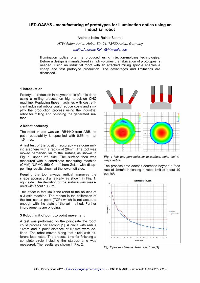
A first test of the position accuracy was done mill-ing a sphere with a radius of 26mm. The tool was moved perpendicular to the surface as shown in Fig. 1, upper left side. The surface then was measured with a coordinate measuring machine (CMM) “UPMC 550 Carat” from Zeiss with disap-pointing results shown at the lower left side.
Keeping the tool always vertical improves the shape accuracy dramatically as shown in Fig. 1, right side. The deviation of the surface was meas-ured with about 106µm.
This effect in fact limits the robot to the abilities of a 3 axis machine. The reason is the calibration of the tool center point (TCP) which is not accurate enough with the state of the art method. Further improvements are ongoing.
3 Robot limit of point to point movement
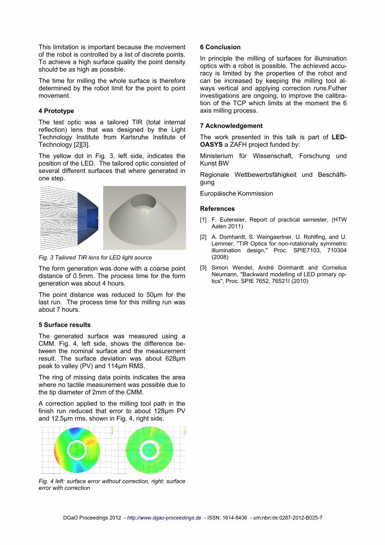
A test was performed on the point rate the robot could process per second [1]. A circle with radius 14mm and a point distance of 0.1mm were de-fined. The robot moved along that circle with dif-ferent feed rates. The process time for finishing a complete circle including the start-up time was measured. The results are shown in Fig. 2.
Fig. 1 left: tool perpendicular to surface, right: tool al-ways vertical
The process time doesn’t decrease beyond a feed rate of 4mm/s indicating a robot limit of about 40 points/s.
Fig. 2 process time vs. feed rate, from [1]
DGaO Proceedings 2012 – http://www.dgao-proceedings.de – ISSN: 1614-8436 – urn:nbn:de:0287-2012-XXXX-Y
This limitation is important because the movement of the robot is controlled by a list of discrete points. To achieve a high surface quality the point density should be as high as possible.
The time for milling the whole surface is therefore determined by the robot limit for the point to point movement.
4 Prototype
The test optic was a tailored TIR (total internal reflection) lens that was designed by the Light Technology Institute from Karlsruhe Institute of Technology [2][3].
The yellow dot in Fig. 3, left side, indicates the position of the LED. The tailored optic consisted of several different surfaces that where generated in one step.
Fig. 3 Tailored TIR lens for LED light source
The form generation was done with a coarse point distance of 0.5mm. The process time for the form generation was about 4 hours.
The point distance was reduced to 50µm for the last run. The process time for this milling run was about 7 hours.
5 Surface results
The generated surface was measured using a CMM. Fig. 4, left side, shows the difference be-tween the nominal surface and the measurement result. The surface deviation was about 628µm peak to valley (PV) and 114µm RMS.
The ring of missing data points indicates the area where no tactile measurement was possible due to the tip diameter of 2mm of the CMM.
A correction applied to the milling tool path in the finish run reduced that error to about 128µm PV and 12.5µm rms, shown in Fig. 4, right side.
Fig. 4 left: surface error without correction, right: surface error with correction
6 Conclusion
In principle the milling of surfaces for illumination optics with a robot is possible. The achieved accu-racy is limited by the properties of the robot and can be increased by keeping the milling tool al-ways vertical and applying correction runs.Futher investigations are ongoing, to improve the calibra-tion of the TCP which limits at the moment the 6 axis milling process.
7 Acknowledgement
The work presented in this talk is part of LED-OASYS a ZAFH project funded by:
Ministerium für Wissenschaft, Forschung und Kunst BW
Regionale Wettbewerbsfähigkeit und Beschäfti-gung
Europäische Kommission
References [1] F. Euteneier, Report of practical semester, (HTW
Aalen 2011)
[2] A. Domhardt, S. Weingaertner, U. Rohlfing, and U. Lemmer, "TIR Optics for non-rotationally symmetric illumination design," Proc. SPIE7103, 710304 (2008)
[3] Simon Wendel, André Domhardt and Cornelius Neumann, "Backward modelling of LED primary op-tics", Proc. SPIE 7652, 76521I (2010)