led - tridonic.com€¦ · led product description ... tc shows the thermal limit for safety reason...
TRANSCRIPT

www.tridonic.com 1Subject to change without notice.
Data sheet 09/15-LED292-0
LED light engine / OLEDLED compact
Product description
• For general lighting application
• Typ. luminous flux category: 2,000/3,000 lm
• High efficacy up to 126 lm/W for the LED module at tp = 25 °C
• Small LES diameter (light emitting surface) enables narrow beam
angle for spotlights
• Excellent thermal management by COB technology
• Uniform radiation with Dam&Fill technology
• Cooling required
• Flexible operating modes
ÈStandards, page 3
Colour temperatures and tolerances, page 7 and 8
Umodule SLE G5 17mm R SNC, SLE G5 17mm FAS R SNC, SLE G5 17mm TINGE R SNCumodule SLE ESSENCE
w
www.tridonic.com 2Subject to change without notice.
Data sheet 09/15-LED292-0
LED light engine / OLEDLED compact
Specific technical dataType Photo-
metric code
Forward current3 4 5
Luminous flux at tp = 25 °C2
Luminous flux at tp = 65 °C2
Power consumption7
Min. forward voltage at tp = 65 °C
Max. forward voltage at tp = 25 °C
Luminous efficacy module at tp = 25 °C
Luminous efficacy module at tp = 65 °C
Colour rendering index CRI
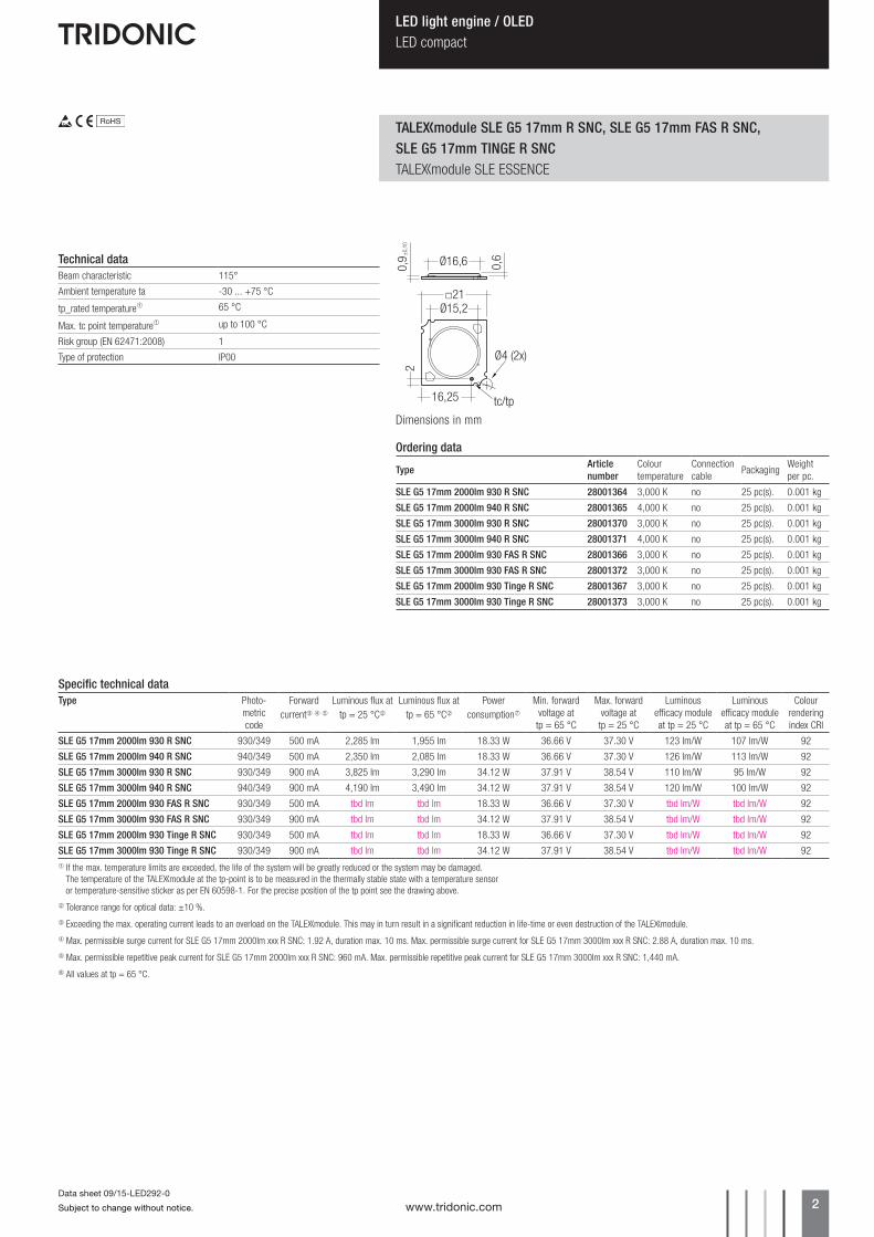
SLE G5 17mm 2000lm 930 R SNC 930/349 500 mA 2,285 lm 1,955 lm 18.33 W 36.66 V 37.30 V 123 lm/W 107 lm/W 92
SLE G5 17mm 2000lm 940 R SNC 940/349 500 mA 2,350 lm 2,085 lm 18.33 W 36.66 V 37.30 V 126 lm/W 113 lm/W 92
SLE G5 17mm 3000lm 930 R SNC 930/349 900 mA 3,825 lm 3,290 lm 34.12 W 37.91 V 38.54 V 110 lm/W 95 lm/W 92
SLE G5 17mm 3000lm 940 R SNC 940/349 900 mA 4,190 lm 3,490 lm 34.12 W 37.91 V 38.54 V 120 lm/W 100 lm/W 92
SLE G5 17mm 2000lm 930 FAS R SNC 930/349 500 mA tbd lm tbd lm 18.33 W 36.66 V 37.30 V tbd lm/W tbd lm/W 92
SLE G5 17mm 3000lm 930 FAS R SNC 930/349 900 mA tbd lm tbd lm 34.12 W 37.91 V 38.54 V tbd lm/W tbd lm/W 92
SLE G5 17mm 2000lm 930 Tinge R SNC 930/349 500 mA tbd lm tbd lm 18.33 W 36.66 V 37.30 V tbd lm/W tbd lm/W 92
SLE G5 17mm 3000lm 930 Tinge R SNC 930/349 900 mA tbd lm tbd lm 34.12 W 37.91 V 38.54 V tbd lm/W tbd lm/W 921 If the max. temperature limits are exceeded, the life of the system will be greatly reduced or the system may be damaged. The temperature of the umodule at the tp-point is to be measured in the thermally stable state with a temperature sensor or temperature-sensitive sticker as per EN 60598-1. For the precise position of the tp point see the drawing above.
2 Tolerance range for optical data: ±10 %.
3 Exceeding the max. operating current leads to an overload on the umodule. This may in turn result in a significant reduction in life-time or even destruction of the umodule.
4 Max. permissible surge current for SLE G5 17mm 2000lm xxx R SNC: 1.92 A, duration max. 10 ms. Max. permissible surge current for SLE G5 17mm 3000lm xxx R SNC: 2.88 A, duration max. 10 ms.
5 Max. permissible repetitive peak current for SLE G5 17mm 2000lm xxx R SNC: 960 mA. Max. permissible repetitive peak current for SLE G5 17mm 3000lm xxx R SNC: 1,440 mA.
6 All values at tp = 65 °C.
Technical dataBeam characteristic 115°
Ambient temperature ta -30 ... +75 °C
tp_rated temperature1 65 °C
Max. tc point temperature1 up to 100 °C
Risk group (EN 62471:2008) 1
Type of protection IP00
Umodule SLE G5 17mm R SNC, SLE G5 17mm FAS R SNC, SLE G5 17mm TINGE R SNCumodule SLE ESSENCE
0,6
0,9 ±
0,10
Ø16,6
Ø15,2□21
216,25 tc/tp
Ø4 (2x)
Dimensions in mm
Ordering data
Type Article number
Colour temperature
Connection cable
PackagingWeight per pc.
SLE G5 17mm 2000lm 930 R SNC 28001364 3,000 K no 25 pc(s). 0.001 kg
SLE G5 17mm 2000lm 940 R SNC 28001365 4,000 K no 25 pc(s). 0.001 kg
SLE G5 17mm 3000lm 930 R SNC 28001370 3,000 K no 25 pc(s). 0.001 kg
SLE G5 17mm 3000lm 940 R SNC 28001371 4,000 K no 25 pc(s). 0.001 kg
SLE G5 17mm 2000lm 930 FAS R SNC 28001366 3,000 K no 25 pc(s). 0.001 kg
SLE G5 17mm 3000lm 930 FAS R SNC 28001372 3,000 K no 25 pc(s). 0.001 kg
SLE G5 17mm 2000lm 930 Tinge R SNC 28001367 3,000 K no 25 pc(s). 0.001 kg
SLE G5 17mm 3000lm 930 Tinge R SNC 28001373 3,000 K no 25 pc(s). 0.001 kg
www.tridonic.com 3Subject to change without notice.
Data sheet 09/15-LED292-0
LED light engine / OLEDLED compact
2. Thermal details
2.1 tp point, ambient temperature and life-time
The temperature at tp reference point is crucial for the light output and life-time of a u product.The operating temperature of a u product is crucial for the light output, the product life-time but also for the product safety.The thermal limits can be checked at the tp/tc point and at tr. In chapter 5.3 the lumen maintenance is shown in relation to the temperature at tp. tp,rated shows the temperature at which the rated values are reached.tc shows the thermal limit for safety reason und must never be exceeded under normal conditions.For the interchangeablity with other Zhaga products, tr,max is specified directly at the thermal interface to the heatsink of the luminaire.
For umodule SLE G5 R SNC a tp temperature of 65 °C has to be complied in order to achieve an optimum between heat sink requirements, light output and life-time.
Compliance with the maximum permissible reference temperature at the tp point must be checked under operating conditions in a thermally stable state. The maximum value must be determined under worst-case conditions for the relevant application.
1. Standards
EN 62031EN 62471EN 61547EN 55015IEC 62717
1st digit 2nd + 3rd digit 4th digit 5th digit 6th digit
Code CRIColour temperature in
Kelvin x 100McAdam
initial
McAdam after 25% of the
life-time (max.6000h)
Luminous flux after 25% of the life-time (max.6000h)
Code Luminous flux7 70 – 79 7 ≥ 70 %8 80 – 89 8 ≥ 80 %9 ≥90 9 ≥ 90 %
1.1 Photometric code
Key for photometric code, e. g. 830 / 349
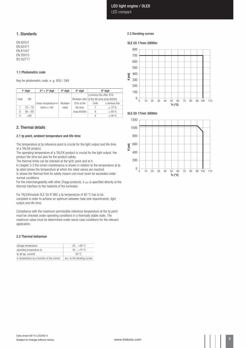
2.2 Thermal behaviour
storage temperature -30 ... +80 °Coperating temperature ta -30 ... +75 °Ctp (at typ. current) 65 °Ctc temperature as a function of the current acc. to the derating curves
2.3 Derating curves
SLE G5 17mm 2000lm
SLE G5 17mm 3000lm
0
100
200
300
400
500
600
700
0 10 20 30 7040 50 60 11080 90 100Tc [°C]
If [m
A]
800
0
200
400
600
800
1000
1200
0 10 20 30 7040 50 60 11080 90 100Tc [°C]
If [m
A]

www.tridonic.com 4Subject to change without notice.
Data sheet 09/15-LED292-0
LED light engine / OLEDLED compact
2.4 Thermal design and heat sink
The rated life of u products depends to a large extent on the temperature. If the permissible temperature limits are exceeded, the life of the umodule SLE G5 R SNC will be greatly reduced or the umodule SLE G5 R SNC may be destroyed.
Therefore the umodule SLE G5 R SNC needs to be mounted onto a heat sink which does not exceed the value for Rth,max.
Tridonic’s excellent thermal design for the umodule SLE G5 R SNC products provides the lowest thermal resistance and therefore allowing new compact designs without sacrificing quality, safety and life-time.
3. Installation / wiring
3.1 Electrical supply/choice of LED Driver
umodule SLE G5 R SNC from Tridonic are not protected against overvoltages, overcurrents, overloads or short-circuit currents. Safe and reliable operation can only be guaranteed in conjunction with a LED Driver which complies with the relevant standards. The use of u LED Drivers from Tridonic in combination with umodule SLE G5 R SNC guarantees the necessary protection for safe and reliable operation.
umodule SLE G5 R SNC are basic isolated up to 75 V against ground and can be mounted directly on earthed metal parts of the luminaire. If the max. output voltage of the LED Driver (also against earth) is above 75 V, an additional isolation between LED module and heat sink is required (for example by isolated thermal pads) or by a suitable luminaire construction.At voltages > 60 V an additional protection against direct touch (test finger) to the light emitting side of the module has to be guaranteed. This is typically achieved by means of a non removable light distributor over the module.
If a LED Driver other than Tridonic uconverter is used, it must provide the fol-lowing protection:• Short-circuit protection• Overload protection• Overtemperature protection
umodule SLE G5 R SNC must be supplied by a constant current LED Driver.Operation with a constant voltage LED Driver will lead to an irreversible damage of the module.
Wrong polarity can damage the umodule SLE G5 R SNC.
2.5 Heat sink values
NotesThe actual cooling can differ because of the material, the structural shape, outside influences and the installation situation. A thermal connection between umodule SLE G5 R SNC and heat sink with heat-conducting paste or heat conducting adhesive film is absolutely necessary.Additionally the umodule SLE G5 R SNC has to be fixed on the heat sink with M3 screws to optimise the thermal connection.Use of thermal interface material with thermal conductivity of l > 1 W/mK and layer thickness of interface material with max. 50 µm or a similar interface material where the quotient of layer thickness and thermal conductivity b < 50 µmmK/W.
SLE G5 17mm 3000lmta tp Operating current Rth, hs-a Cooling area 25 °C 65 °C 900 mA 1.70 K/W 392 cm2
30 °C 65 °C 900 mA 1.47 K/W 453 cm2
40 °C 65 °C 900 mA 1.02 K/W 654 cm2
50 °C 65 °C 900 mA 0.57 K/W 1.177 cm2
SLE G5 17mm 2000lmta tp Operating current Rth, hs-a Cooling area 25 °C 55 °C 500 mA 3.34 K/W 200 cm2
30 °C 55 °C 500 mA 2.91 K/W 229 cm2
40 °C 55 °C 500 mA 2.04 K/W 326 cm2
50 °C 55 °C 500 mA 1.18 K/W 565 cm2
3.3 Wiring type and cross section
The wiring has to be solid cable with a cross section of 0.5 to 0.75 mm² or with stranded wire with soldered ends with a cross section of 0.5 mm².
3.2 Wiring example
–+
Udriver LC...
LN
–
–
+
+
Thermal resistance Rth, j-p
Luminous flux Rth, j-p
2,000 lm 1.10 K/W3,000 lm 0.87 K/W

www.tridonic.com 5Subject to change without notice.
Data sheet 09/15-LED292-0
LED light engine / OLEDLED compact
3.5 EOS/ESD safety guidelines
The device / module contains components that are sensitive to electro-static discharge and may only be installed in the factory and on site if appropriate EOS/ESD protection measures have been taken. No special measures need be taken for devices/modules with enclosed casings (contact with the pc board not possible), just normal installation prac-tice. Please note the requirements set out in the document EOS / ESD guidelines (Guideline_EOS_ESD.pdf) at: http://www.tridonic.com/esd-protection
3.4 Mounting instruction
umodule SLE G5 R SNC from Tridonic which have to be installed on a heat sink have to be connected with heat-conducting paste or heat conducting adhesive film and fixed with M3 screws.
The fixing/cooling surface must be cleaned by removing all dirt, dust and grease before installing the u modules.
None of the components of the umodule SLE G5 R SNC (substrate, LED, electronic components etc.) may be exposed to tensile or compres-sive stresses.
Max. torque for fixing: 0.5 Nm.
The umodule SLE G5 R SNC modules are mounted with 2 screws per module. In order not to damage the modules only rounded head screws and an additional plastic flat washer should be used.
For further information please refer to to the brochure entitled “Technical Design-In-Guide SLE GEN4”.
Chemical substance may harm the LED module. Chemical reactions could lead to colour shift, reduced luminous flux or a total failure of the module caused by corrosion of electrical connections.
Materials which are used in LED applications (e.g. sealings, adhesives) must not produce dissolver gas. They must not be condensation curing based, acetate curing based or contain sulfur, chlorine or phthalate.Avoid corrosive atmosphere during usage and storage.
www.tridonic.com 6Subject to change without notice.
Data sheet 09/15-LED292-0
LED light engine / OLEDLED compact
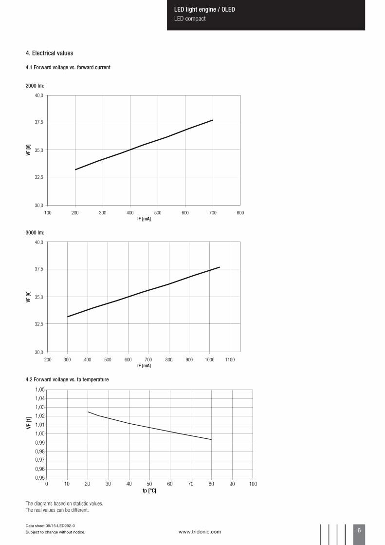
The diagrams based on statistic values.The real values can be different.
4. Electrical values
4.2 Forward voltage vs. tp temperature
0,96
0,97
0,99
1,00
1,01
1,02
1,04
1,05
10 20 30 40tp [°C]
0
0,98
1,03
0,9510050 60 70 80 90
VF [1
]
4.1 Forward voltage vs. forward current
30,0
32,5
37,5
35,0
40,0
100 200 300 400 500 600 700 800IF [mA]
VF [V
]
30,0
32,5
37,5
35,0
40,0
200 400 500300 600 700 800 900 1000 1100IF [mA]
VF [V
]
2000 lm:
3000 lm:

www.tridonic.com 7Subject to change without notice.
Data sheet 09/15-LED292-0
LED light engine / OLEDLED compact
5. Photometric characteristics
5.1 Coordinates and tolerances according to CIE 1931
The specified colour coordinates are measured integral after a settling time of 100 ms. The current impuls depends on the module type.
The ambient temperature of the measurement is ta = 25 °C.The measurement tolerance of the colour coordinates are ± 0.01.
Module type Current impulseSLE G5 17mm 2000lm 500 mASLE G5 17mm 3000lm 900 mA
MacAdam ellipse: 3SDCM
MacAdam ellipse: 3SDCM
3,000 Kx0 y0
Centre 0.4300 0.4016
4,000 Kx0 y0
Centre 0.3761 0.3740
380 420 460 500 540 580 620 660 700 740 7800
0.09
0.07
0.06
0.04
0.05
0.03
0.02
0.01
0.08
wave length [nm]
norm
. int
ensi
ty [W
/nm
]
380 420 460 500 540 580 620 660 700 740 7800
0.09
0.07
0.06
0.04
0.05
0.03
0.02
0.01
0.08
wave length [nm]
norm
. int
ensi
ty [W
/nm
]
0,3800
0,3850
0,3900
0,3950
0,4000
0,4050
0,4100
0,4150
0,4200
0,41
00
0,41
50
0,42
00
0,42
50
0,43
00
0,43
50
0,44
00
0,44
50
0,45
00
0,3550
0,3600
0,3650
0,3700
0,3750
0,3800
0,3850
0,3900
0,3950
0,35
50
0,36
00
0,36
50
0,37
00
0,37
50
0,38
00
0,38
50
0,39
00
0,39
50

www.tridonic.com 8Subject to change without notice.
Data sheet 09/15-LED292-0
LED light engine / OLEDLED compact
380 420 460 500 540 580 620 660 700 740 7800
0.12
0.08
0.06
0.04
0.02
0.10
wave length [nm]
norm
. int
ensi
ty [W
/nm
]
380 420 460 500 540 580 620 660 700 740 7800
0.09
0.07
0.06
0.04
0.05
0.03
0.02
0.01
0.08
wave length [nm]
norm
. int
ensi
ty [W
/nm
]
MacAdam Ellipse: 3SDCM
MacAdam Ellipse: 3SDCM
FASHIONx0 y0
Centre 0.4177 0.3918
Tingex0 y0
Centre 0.4330 0.3960
0,3700
0,3750
0,3800
0,3850
0,3900
0,3950
0,4000
0,4050
0,4100
0,40
00
0,40
50
0,41
00
0,41
50
0,42
00
0,42
50
0,43
00
0,43
50
0,44
00
0,3750
0,3800
0,3850
0,3900
0,3950
0,4000
0,4050
0,4100
0,4150
0,41
50
0,42
00
0,42
50
0,43
00
0,43
50
0,44
00
0,44
50
0,45
00
0,45
50

www.tridonic.com 9Subject to change without notice.
Data sheet 09/15-LED292-0
LED light engine / OLEDLED compact
5.2 Light distribution
0°
20
20
20 40
40
60
60
80
100
80 100 40 6080100
10°-10° 20°-20°-30°
-40°
-50°
-60°
30°40°
50°
60°
70°
80°
90°-90°0
norm
. int
ensit
y [%
]
0,94
0,96
0,98
1,00
1,02
1,04
1,06
1,08
1,10
1,12
10 20 30 4000,92
50 60 70 80 90tp [°C]
rel.
lum
inou
s flu
x
5.3 Relative luminous flux vs. tp temperature
140
120
100
90
80
70
200 400 600 800IF [mA]
0
110
130
5018001000 1200 1400 1600
rel.
lum
inou
s flu
x [%
]
60
5.4 Relative luminous flux vs. forward current
3000 lm
2000 lm