led elevated taxiway edge light - multi electric
TRANSCRIPT

Document UT-MT-0782_EN Page 1 of 23 Via della Solidarietà, 2/1
40056 Valsamoggia Loc. Crespellano
BOLOGNA ITALY
Edition 19/03/2018 Supersedes edition 19/05/2017
Via della Solidarietà, 2/1 – 40056 Valsamoggia - Italy
QUESTA COPIA NON E’ FIRMATA PERCHE’ REGISTRATA E DISTRIBUITA TRAMITE SISTEMA AUTOMATICO DI GESTIONE DEL PATRIMONIO INFORMATIVO (PUO’ ESSERE FIRMATA A RICHIESTA). QUESTO DOCUMENTO E’ PROPRIETA’
RISERVATA DI OCEM; IL SUO CONTENUTO NON PUO’ ESSERE DIVULGATO NE’ MODIFICATO SENZA IL CONSENSO SCRITTO DI OCEM.
LED ELEVATED TAXIWAY EDGE LIGHT
LTE
INSTRUCTION MANUAL FOR USE, INSTALLATION
AND MAINTENANCE
Compiled by: Emidio Rauli Approved by: Matteo Mazzotti
N° Attachments: 1 Copy n°:

Document UT-MT-0782_EN Page 2 of 23
Edition 19/03/2018 Supersedes edition 19/05/2017
Via della Solidarietà, 2/1 – 40056 Valsamoggia - Italy
QUESTA COPIA NON E’ FIRMATA PERCHE’ REGISTRATA E DISTRIBUITA TRAMITE SISTEMA AUTOMATICO DI GESTIONE DEL PATRIMONIO INFORMATIVO (PUO’ ESSERE FIRMATA A RICHIESTA). QUESTO DOCUMENTO E’ PROPRIETA’
RISERVATA DI OCEM; IL SUO CONTENUTO NON PUO’ ESSERE DIVULGATO NE’ MODIFICATO SENZA IL CONSENSO SCRITTO DI OCEM.
LED ELEVATED TAXIWAY EDGE LIGHT LTE
INSTRUCTION MANUAL FOR USE, INSTALLATION AND MAINTENANCE
LIMITED PRODUCT WARRANTY
THE FOLLOWING WARRANTY IS EXCLUSIVE AND IN LIEU OF ALL OTHER WARRANTIES, WHETHER EXPRESS,
IMPLIED OR STATUTORY, INCLUDING, BUT NOT BY WAY OF LIMITATION, ANY WARRANTY OF
MERCHANTABILITY OR FITNESS FOR ANY PARTICULAR PURPOSE.
OCEM - ENERGY TECHNOLOGY warrants to each original Buyer of Products manufactured by the Company
that such Products are at the time of delivery to the Buyer, free of material and workmanship defects,
provided that no warranty is made with respect to:
(a) any Product, which has been repaired or altered in such a way, in Company’s judgement, as to affect
the Product adversely;
(b) any Product which has, in Company’s judgement, been subject to negligence, accident or improper
storage;
(c) any Product which has not been operated and maintained in accordance with normal practice and in
conformity with recommendations and published specification of Company;
(d) the breaking of the warranty seals, if present, determines the immediate termination of the warranty;
and,
OCEM - ENERGY TECHNOLOGY’s obligation under this warranty is limited to use reasonable efforts to
repair or, at its option, replace, during normal working hours at the facility of the Company, any Product
which in its judgement proved not to be as warranted within the applicable warranty period. All costs of
transportation of Products claimed not to be warranted and of those repaired or replaced, to or from the
facility of the Company shall be borne by Purchaser. Company may require the return of any Product
claimed not to be as warranted to its facility, transportation prepaid by Purchaser, to establish a claim
under this warranty. The cost of labour for the installation of a repaired or replaced Product shall be
borne by Purchaser. Replacement parts provided under the terms of this warranty are warranted for the
remainder of the warranty period of the Products upon which they are installed to the same extent as if
such parts were original components thereof. Warranty services provided under the Agreement do not
assure uninterrupted operations of Products; Company does not assume any liability for damages caused
by any delays involving warranty service.
IMPORTANT: READ THIS DOCUMENT
Before proceeding to the operations of installation, commissioning, operation, maintenance or disposal,
carefully read the entire document.
SAFETY INFORMATION
Extreme caution should be exercised when working with this equipment; it is normally used or connected
to circuits that operate at dangerous voltages and can be fatal.
The following section contains important safety information that you must follow when installing and
using the apparatus.
Misuse of the equipment or lack of care in applying safety procedures and prescriptions specified in this
document, may result in a hazard.
Avoid contact with voltage or current sources.
For no reason the protections and the safety devices must be removed.

Document UT-MT-0782_EN Page 3 of 23
Edition 19/03/2018 Supersedes edition 19/05/2017
Via della Solidarietà, 2/1 – 40056 Valsamoggia - Italy
QUESTA COPIA NON E’ FIRMATA PERCHE’ REGISTRATA E DISTRIBUITA TRAMITE SISTEMA AUTOMATICO DI GESTIONE DEL PATRIMONIO INFORMATIVO (PUO’ ESSERE FIRMATA A RICHIESTA). QUESTO DOCUMENTO E’ PROPRIETA’
RISERVATA DI OCEM; IL SUO CONTENUTO NON PUO’ ESSERE DIVULGATO NE’ MODIFICATO SENZA IL CONSENSO SCRITTO DI OCEM.
LED ELEVATED TAXIWAY EDGE LIGHT LTE
INSTRUCTION MANUAL FOR USE, INSTALLATION AND MAINTENANCE
OPERATION ON THE EQUIPMENT - SKILLS
Operation on the equipment and access to its internal parts shall be done by experienced personnel,
adequately trained and aware of the risks related to electricity and high voltages.
Safety rules shall be adopted when operating on the equipment, or on cables and other apparatus
connected to the it
DO NOT OPERATE ON ENERGIZED CIRCUITS
Do not carry out any operation on the converter or on apparatus connected to it when the circuits are
energized.
WHEN HANDLING AND SERVICING THIS EQUIPMENT, OBSERVE PRECAUTIONS FOR HIGH VOLTAGE
EQUIPMENT.
Before any access, inspection or intervention, be sure to have switched-off the unit, opened the main
circuit breaker and removed the supply to the unit (by opening the circuit breaker/switch on the
distribution board at the beginning of the supply line).
Then wait discharge time (at least 5 minutes), ground carefully the system, and check for voltage
presence before accessing..
REANIMATION
The maintenance staff must be aware of the risks related to electricity, criteria to prevent the risk of
electric shock and resuscitation techniques
CE MARK
This equipment complies with the requirements of European regulations for the CE mark.The
user has to respect all prescriptions reported in this document.
This equipment complies with the requirements of the EEC directives 2004/108/EEC and
2006/95/EEC with regard to “Electromagnetic Compatibility” and “Low Voltage Electrical
Apparatus” respectively.
OUT OF SERVICE
In case of dismantling, decommissioning, destruction, disposal, the user shall follow all the required
precautions for component and material elimination, according to local rules and applicable law.
Document UT-MT-0782_EN Page 4 of 23
Edition 19/03/2018 Supersedes edition 19/05/2017
LED ELEVATED TAXIWAY EDGE LIGHT LTE
INSTRUCTION MANUAL FOR USE, INSTALLATION AND MAINTENANCE
Via della Solidarietà, 2/1 – 40056 Valsamoggia - Italy
QUESTA COPIA NON E’ FIRMATA PERCHE’ REGISTRATA E DISTRIBUITA TRAMITE SISTEMA AUTOMATICO DI GESTIONE DEL PATRIMONIO INFORMATIVO (PUO’ ESSERE FIRMATA A RICHIESTA). QUESTO DOCUMENTO E’ PROPRIETA’
RISERVATA DI OCEM; IL SUO CONTENUTO NON PUO’ ESSERE DIVULGATO NE’ MODIFICATO SENZA IL CONSENSO SCRITTO DI OCEM.
EDITIONS
Date
07/24/2013
09/24/2013
11/14/2013
First issue
Added the light fixture heights up to 760 mm
Updated chapter “Cable lead with plug” and “List of the recommended spare
parts”
11/03/2014 New address of the Company
19/05/2017
Deleted § “List of the recommended spare parts” and added relevant
attachment
Added reference to FAA 150/5345-30 for installation and specified the ground
wire used in the main features.
19/03/2018 Replaced gasket, ring nut and added o-ring
REVISIONS
Index Date Description Edited by Approved by
LIST OF EFFECTIVE PAGES
From page 1 to page 23

Document UT-MT-0782_EN Page 5 of 23
Edition 19/03/2018 Supersedes edition 19/05/2017
LED ELEVATED TAXIWAY EDGE LIGHT LTE
INSTRUCTION MANUAL FOR USE, INSTALLATION AND MAINTENANCE
Via della Solidarietà, 2/1 – 40056 Valsamoggia - Italy
QUESTA COPIA NON E’ FIRMATA PERCHE’ REGISTRATA E DISTRIBUITA TRAMITE SISTEMA AUTOMATICO DI GESTIONE DEL PATRIMONIO INFORMATIVO (PUO’ ESSERE FIRMATA A RICHIESTA). QUESTO DOCUMENTO E’ PROPRIETA’
RISERVATA DI OCEM; IL SUO CONTENUTO NON PUO’ ESSERE DIVULGATO NE’ MODIFICATO SENZA IL CONSENSO SCRITTO DI OCEM.
INDEX
LIMITED PRODUCT WARRANTY ......................................................................................................... 2
SAFETY INFORMATION ...................................................................................................................... 2
EDITIONS ........................................................................................................................................... 4
REVISIONS .......................................................................................................................................... 4
LIST OF EFFECTIVE PAGES .................................................................................................................. 4
INDEX ................................................................................................................................................. 5
INDEX OF FIGURES ............................................................................................................................. 6
LIST OF ATTACHMENTS ..................................................................................................................... 6
1 GENERAL ......................................................................................................................... 7
2 MAIN FEATURES ............................................................................................................. 7
2.1 ELECTRONIC SECTION ................................................................................................... 10
2.1.1 Current / current conversion circuit (patented) ................................................. 10
2.1.2 LED command circuit .......................................................................................... 10
2.1.3 Control circuit ..................................................................................................... 11
2.2 ARCTIC KIT .................................................................................................................... 11
3 INSTALLATION .............................................................................................................. 11
3.1 CIVIL WORKS ................................................................................................................. 11
3.2 INSTALLING THE LIGH UNIT .......................................................................................... 12
3.3 SECONDARY WIRING .................................................................................................... 14
4 MAINTENANCE ............................................................................................................. 15
4.1 MAINTENANCE PROGRAM ........................................................................................... 15
4.1.1 Periodical Checks ................................................................................................ 15
4.1.2 Snowplow Operations ......................................................................................... 15
4.2 REMOVING AND OPENING THE LIGHT UNIT ................................................................ 16
4.2.1 Removing the fixture .......................................................................................... 16
4.3 LENS CLEANING ............................................................................................................ 16
4.3.1 Prism outside cleaning ........................................................................................ 16
4.4 LENS REPLACEMENT ..................................................................................................... 16
4.5 LED MODULE REPLACEMENT ....................................................................................... 17
4.6 ELECTRONIC REPLACEMENT ......................................................................................... 18
4.7 BREAKABLE COUPLING REPLACEMENT ........................................................................ 18
4.8 CABLE LEAD WITH PLUG ............................................................................................... 19
4.8.1 Removing the cable lead with plug ..................................................................... 19
4.8.2 Installing the new cable lead with plug .............................................................. 19
4.9 ARCTIC KIT REPLACEMENT ........................................................................................... 19
4.9.1 Thermostat .......................................................................................................... 19
4.9.2 Heater ................................................................................................................. 20
4.10 MONITORING ............................................................................................................... 21
5 TROUBLESHOOTING ...................................................................................................... 23
Document UT-MT-0782_EN Page 6 of 23
Edition 19/03/2018 Supersedes edition 19/05/2017
LED ELEVATED TAXIWAY EDGE LIGHT LTE
INSTRUCTION MANUAL FOR USE, INSTALLATION AND MAINTENANCE
Via della Solidarietà, 2/1 – 40056 Valsamoggia - Italy
QUESTA COPIA NON E’ FIRMATA PERCHE’ REGISTRATA E DISTRIBUITA TRAMITE SISTEMA AUTOMATICO DI GESTIONE DEL PATRIMONIO INFORMATIVO (PUO’ ESSERE FIRMATA A RICHIESTA). QUESTO DOCUMENTO E’ PROPRIETA’
RISERVATA DI OCEM; IL SUO CONTENUTO NON PUO’ ESSERE DIVULGATO NE’ MODIFICATO SENZA IL CONSENSO SCRITTO DI OCEM.
INDEX OF FIGURES
Figure 1 – Exploded View .................................................................................................................. 8
Figure 2 – Part List ............................................................................................................................. 9
Figure 3 - Complete P/N identification............................................................................................ 10
Figure 4 – Civil Works ...................................................................................................................... 12
Figure 5 – Levelling Device .............................................................................................................. 14
Figure 6 – Removing the Lens ......................................................................................................... 17
Figure 7 – Reassembly the Light Unit .............................................................................................. 18
Figure 8 – Cable lead with plug, Grounding cable and Arctic kit .................................................... 21
Figure 9 - Restoring the Monitoring Device .................................................................................... 22
LIST OF ATTACHMENTS
UC-PU-0278 - LIST OF THE RECOMMENDED SPARE PARTS

Document UT-MT-0782_EN Page 7 of 23
Edition 19/03/2018 Supersedes edition 19/05/2017
LED ELEVATED TAXIWAY EDGE LIGHT LTE
INSTRUCTION MANUAL FOR USE, INSTALLATION AND MAINTENANCE
Via della Solidarietà, 2/1 – 40056 Valsamoggia - Italy
QUESTA COPIA NON E’ FIRMATA PERCHE’ REGISTRATA E DISTRIBUITA TRAMITE SISTEMA AUTOMATICO DI GESTIONE DEL PATRIMONIO INFORMATIVO (PUO’ ESSERE FIRMATA A RICHIESTA). QUESTO DOCUMENTO E’ PROPRIETA’
RISERVATA DI OCEM; IL SUO CONTENUTO NON PUO’ ESSERE DIVULGATO NE’ MODIFICATO SENZA IL CONSENSO SCRITTO DI OCEM.
1 GENERAL
LTE elevated LED taxiway edge light is low intensity, omnidirectional steady burning
type.
These fixtures are intended for use as taxiway edge light, in order to provide a visual
aid to the moving aircraft.
LTE lights are in compliance with ICAO Annex 14 Vol.1, FAA AC 150/5345-46, IEC TS
61827 and NATO-STANAG 3316.
The fixtures described in this manual are designed to be connected to series circuit,
replacing those equipped with incandescent lamps, fed through standard isolation
transformers connected to CCR with variable current from 2.8 A to 6.6 A.
Location of these fittings shall be in compliance with ICAO - Annex 14, STANAG 3316
and FAA 150/5340-30.
2 MAIN FEATURES
The fixture consists of:
� heat resistant transparent glass lens; it is mechanically secured to the body by
metal threaded ring with flat gasket
� aluminium body mounted on the pole using three screws. These screws also allow
the levelling of equipment
� the power supply/control PCB and the LED circuit are mounted on the aluminium
inner body
� steel 1-inch-tube, available in different length, connecting the main body and
fragile joint; to lock the tube, the breakable coupling is equipped with one screw
� aluminium breakable coupling provided with a breakable groove, meeting FAA
Specs, and with a lower 1"1/2 - 12 UNF male thread. On request the male
threading may be 2"-11 1/2 NPS or 2" GAS
� two, single-pole neoprene cable leads, size 2.5 mm2, 0.3 m long, with plug
meeting FAA Specs L-823; a wire, XHHW, 600V, AWG12 type is provided for
grounding purpose
� a LED module, consisting of one blue LED, mounted on a PCB complete with a
dedicated optic to collect the LED luminous flux so to maximize the light output
Power consumption: 6 VA. All hardware is made of stainless steel.
See “Complete P/N identification” figure for P/N information.

Document UT-MT-0782_EN Page 8 of 23
Edition 19/03/2018 Supersedes edition 19/05/2017
LED ELEVATED TAXIWAY EDGE LIGHT LTE
INSTRUCTION MANUAL FOR USE, INSTALLATION AND MAINTENANCE
Via della Solidarietà, 2/1 – 40056 Valsamoggia - Italy
QUESTA COPIA NON E’ FIRMATA PERCHE’ REGISTRATA E DISTRIBUITA TRAMITE SISTEMA AUTOMATICO DI GESTIONE DEL PATRIMONIO INFORMATIVO (PUO’ ESSERE FIRMATA A RICHIESTA). QUESTO DOCUMENTO E’ PROPRIETA’
RISERVATA DI OCEM; IL SUO CONTENUTO NON PUO’ ESSERE DIVULGATO NE’ MODIFICATO SENZA IL CONSENSO SCRITTO DI OCEM.
Figure 1 – Exploded View

Document UT-MT-0782_EN Page 9 of 23
Edition 19/03/2018 Supersedes edition 19/05/2017
LED ELEVATED TAXIWAY EDGE LIGHT LTE
INSTRUCTION MANUAL FOR USE, INSTALLATION AND MAINTENANCE
Via della Solidarietà, 2/1 – 40056 Valsamoggia - Italy
QUESTA COPIA NON E’ FIRMATA PERCHE’ REGISTRATA E DISTRIBUITA TRAMITE SISTEMA AUTOMATICO DI GESTIONE DEL PATRIMONIO INFORMATIVO (PUO’ ESSERE FIRMATA A RICHIESTA). QUESTO DOCUMENTO E’ PROPRIETA’
RISERVATA DI OCEM; IL SUO CONTENUTO NON PUO’ ESSERE DIVULGATO NE’ MODIFICATO SENZA IL CONSENSO SCRITTO DI OCEM.
No. Description Qty
1 FAA L-823 plug ..................................................................................................... 1
2 Fixture grounding wire ......................................................................................... 1
3 Breakable coupling .............................................................................................. 1
4 Standard 1-inch tube ........................................................................................... 1
5 Body with slipfitter............................................................................................... 1
6 Electronic ............................................................................................................. 1
7 LED module with accessories ............................................................................... 1
8 Gasket for lens ..................................................................................................... 1
9 Lens ...................................................................................................................... 1
10 Lens locking ring ................................................................................................... 1
11 Cable gland ........................................................................................................... 1
12 Arctic kit thermostat ............................................................................................ 1
13 Arctic kit heater ................................................................................................... 1
14 O-Ring .................................................................................................................. 1
Figure 2 – Part List
LTE - F - 25 - A - M - A - O
Basic P/N:
Compliance:
I = ICAO - IEC
S = STANAG
F = FAA
Height:
25 = 250 mm
28 = 280 mm
32 = 320 mm
35 = 350 mm
50 = 500 mm
61 = 610 mm
76 = 760 mm
Breakable Coupling:
A = 1”1/2 – 12 UNF
B = 2” – 11 1/2 NPS
C = 2” GAS
Monitoring:
0 = Without Monitoring
M = With Monitoring
Arctic Kit:
0 = Without Arctic Kit
A = With Arctic Kit
Options:
W = White Omnidirectional Approach
R = Red Unserviceability Light
Document UT-MT-0782_EN Page 10 of 23
Edition 19/03/2018 Supersedes edition 19/05/2017
LED ELEVATED TAXIWAY EDGE LIGHT LTE
INSTRUCTION MANUAL FOR USE, INSTALLATION AND MAINTENANCE
Via della Solidarietà, 2/1 – 40056 Valsamoggia - Italy
QUESTA COPIA NON E’ FIRMATA PERCHE’ REGISTRATA E DISTRIBUITA TRAMITE SISTEMA AUTOMATICO DI GESTIONE DEL PATRIMONIO INFORMATIVO (PUO’ ESSERE FIRMATA A RICHIESTA). QUESTO DOCUMENTO E’ PROPRIETA’
RISERVATA DI OCEM; IL SUO CONTENUTO NON PUO’ ESSERE DIVULGATO NE’ MODIFICATO SENZA IL CONSENSO SCRITTO DI OCEM.
Figure 3 - Complete P/N identification
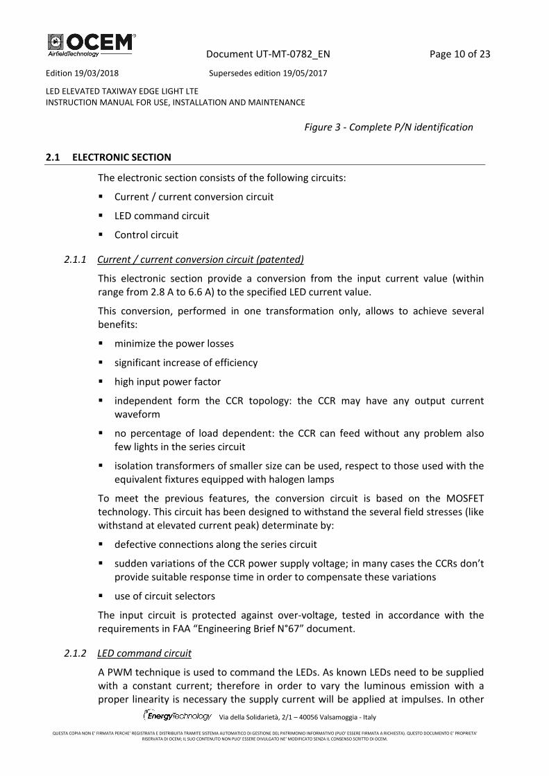
2.1 ELECTRONIC SECTION
The electronic section consists of the following circuits:
� Current / current conversion circuit
� LED command circuit
� Control circuit
2.1.1 Current / current conversion circuit (patented)
This electronic section provide a conversion from the input current value (within
range from 2.8 A to 6.6 A) to the specified LED current value.
This conversion, performed in one transformation only, allows to achieve several
benefits:
� minimize the power losses
� significant increase of efficiency
� high input power factor
� independent form the CCR topology: the CCR may have any output current
waveform
� no percentage of load dependent: the CCR can feed without any problem also
few lights in the series circuit
� isolation transformers of smaller size can be used, respect to those used with the
equivalent fixtures equipped with halogen lamps
To meet the previous features, the conversion circuit is based on the MOSFET
technology. This circuit has been designed to withstand the several field stresses (like
withstand at elevated current peak) determinate by:
� defective connections along the series circuit
� sudden variations of the CCR power supply voltage; in many cases the CCRs don’t
provide suitable response time in order to compensate these variations
� use of circuit selectors
The input circuit is protected against over-voltage, tested in accordance with the
requirements in FAA “Engineering Brief N°67” document.
2.1.2 LED command circuit
A PWM technique is used to command the LEDs. As known LEDs need to be supplied
with a constant current; therefore in order to vary the luminous emission with a
proper linearity is necessary the supply current will be applied at impulses. In other

Document UT-MT-0782_EN Page 11 of 23
Edition 19/03/2018 Supersedes edition 19/05/2017
LED ELEVATED TAXIWAY EDGE LIGHT LTE
INSTRUCTION MANUAL FOR USE, INSTALLATION AND MAINTENANCE
Via della Solidarietà, 2/1 – 40056 Valsamoggia - Italy
QUESTA COPIA NON E’ FIRMATA PERCHE’ REGISTRATA E DISTRIBUITA TRAMITE SISTEMA AUTOMATICO DI GESTIONE DEL PATRIMONIO INFORMATIVO (PUO’ ESSERE FIRMATA A RICHIESTA). QUESTO DOCUMENTO E’ PROPRIETA’
RISERVATA DI OCEM; IL SUO CONTENUTO NON PUO’ ESSERE DIVULGATO NE’ MODIFICATO SENZA IL CONSENSO SCRITTO DI OCEM.
words, the LED luminous output depends on the time of application (duty-cycle) of
constant current impulses.
2.1.3 Control circuit
The main task of the control circuit is to assure the correct LED light emission
according to the series circuit current.
To perform this features, the circuit is provided with a current sensor that generate a
signal proportional to the series circuit current.
This signal is analyzed by a DSP which perform a RMS conversion of the input current.
The RMS conversion give a good accuracy with any input current waveform.
Other functions:
� diagnostic, auxiliary voltage control and LED status control. In case of any LED
failure or relative power supply circuit failure, the electronic control circuit
commands the intervention of the monitoring device so that the secondary side
of the isolation transformer becomes open, like in the case of an incandescent
lamp failure. This features is essential when the monitoring option is required
� events recording (not-volatile memory) for diagnostic purposes
� PC operator interface through serial connection: this features allows to calibrate
the brightness depending on the current, to modify the emission curve, to read
the events occurred during the operating time
2.2 ARCTIC KIT
The optional arctic kit is in compliance with FAA “Engineering Brief N°67” document
and it prevents from the ice over the prisms area.
The arctic kit is connected in series to the PCB and it is consists of a thermostat and
one heater. It starts when the dome temperature is less than about -1°C and turns-
off when the dome temperature reaches about 10°C.
Arctic kit consumption is less than 12 VA.
3 INSTALLATION
3.1 CIVIL WORKS
Each light is usually installed on a suitable concrete block, into which a pipe elbows is
cemented. The isolating transformer is housed into a separate concrete pit which is
normally placed close the above concrete block (Figure 4).
The pit can be placed far from the concrete block too, but in this case a suitable cable
duct has to be provided between the pit and the pipe elbow for passing the
secondary cable.

Document UT-MT-0782_EN Page 12 of 23
Edition 19/03/2018 Supersedes edition 19/05/2017
LED ELEVATED TAXIWAY EDGE LIGHT LTE
INSTRUCTION MANUAL FOR USE, INSTALLATION AND MAINTENANCE
Via della Solidarietà, 2/1 – 40056 Valsamoggia - Italy
QUESTA COPIA NON E’ FIRMATA PERCHE’ REGISTRATA E DISTRIBUITA TRAMITE SISTEMA AUTOMATICO DI GESTIONE DEL PATRIMONIO INFORMATIVO (PUO’ ESSERE FIRMATA A RICHIESTA). QUESTO DOCUMENTO E’ PROPRIETA’
RISERVATA DI OCEM; IL SUO CONTENUTO NON PUO’ ESSERE DIVULGATO NE’ MODIFICATO SENZA IL CONSENSO SCRITTO DI OCEM.
As alternative the assembly pit-pipe elbow can be replaced by a steel sheet base,
which can be used to house the isolating transformer, complete with an upper steel
plate with a threaded sleeve.
Figure 4 – Civil Works
3.2 INSTALLING THE LIGH UNIT
The light is shipped completely assembled including the LED module, except the 1-
inch tube and the breakable coupling which are delivered separately inside the same
carton.
Note: if the fixture has been ordered with an extra height option, the tubing may be
packaged separately.
For the installation of the light the following steps are suggested:
� pass together the secondary cable lead with receptacle and a suitable length of
grounding wire (grounded inside the pit) through the pipe elbow

Document UT-MT-0782_EN Page 13 of 23
Edition 19/03/2018 Supersedes edition 19/05/2017
LED ELEVATED TAXIWAY EDGE LIGHT LTE
INSTRUCTION MANUAL FOR USE, INSTALLATION AND MAINTENANCE
Via della Solidarietà, 2/1 – 40056 Valsamoggia - Italy
QUESTA COPIA NON E’ FIRMATA PERCHE’ REGISTRATA E DISTRIBUITA TRAMITE SISTEMA AUTOMATICO DI GESTIONE DEL PATRIMONIO INFORMATIVO (PUO’ ESSERE FIRMATA A RICHIESTA). QUESTO DOCUMENTO E’ PROPRIETA’
RISERVATA DI OCEM; IL SUO CONTENUTO NON PUO’ ESSERE DIVULGATO NE’ MODIFICATO SENZA IL CONSENSO SCRITTO DI OCEM.
� place the receptacle into the upper threaded section of the pipe elbow, by
holding it between the two plastic rings, and pass the grounding wire through the
rings (in correspondence of break point provided on the rings)
� slide one end of the 1-inch tube over the fixture cable assembly (cable leads with
plug plus yellow-green wire) and into the fixture body until the body bottoms
against the tube
� approach, without tighten, the set screws on the side of the body to the 1-inch
tube
� slide the frangible coupling over the cable assembly (cable leads with plug plus
yellow-green wire) and onto the other end of the 1-inch tube until it bottoms
against the tube
� connect the fixture grounding wire to the grounding wire coming from the pit (or
from the base): splice both the wires and connect them together by using a
crimping connector
� connect the light plug to the secondary receptacle inside the pipe elbow
� slide the frangible coupling down over the plug and tighten it into pipe elbow (or
the base plate) until coupling bottoms out. Push any extra cable length into the 1-
inch tube. Tighten the tube to the coupling with the setscrew on the coupling
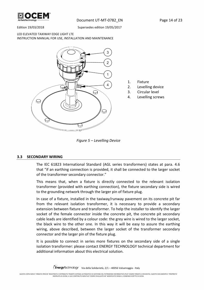
� Place on the lens locking ring the levelling device (P/N 332.3500 available on
request) as shown in Figure 5. Levelling the light body by operating the three
levelling screws until the bubble is centered
� remove the levelling device
Document UT-MT-0782_EN Page 14 of 23
Edition 19/03/2018 Supersedes edition 19/05/2017
LED ELEVATED TAXIWAY EDGE LIGHT LTE
INSTRUCTION MANUAL FOR USE, INSTALLATION AND MAINTENANCE
Via della Solidarietà, 2/1 – 40056 Valsamoggia - Italy
QUESTA COPIA NON E’ FIRMATA PERCHE’ REGISTRATA E DISTRIBUITA TRAMITE SISTEMA AUTOMATICO DI GESTIONE DEL PATRIMONIO INFORMATIVO (PUO’ ESSERE FIRMATA A RICHIESTA). QUESTO DOCUMENTO E’ PROPRIETA’
RISERVATA DI OCEM; IL SUO CONTENUTO NON PUO’ ESSERE DIVULGATO NE’ MODIFICATO SENZA IL CONSENSO SCRITTO DI OCEM.
1. Fixture
2. Levelling device
3. Circular level
4. Levelling screws
Figure 5 – Levelling Device
3.3 SECONDARY WIRING
The IEC 61823 International Standard (AGL series transformers) states at para. 4.6
that “if an earthing connection is provided, it shall be connected to the larger socket
of the transformer secondary connector.”
This means that, when a fixture is directly connected to the relevant isolation
transformer (provided with earthing connection), the fixture secondary side is wired
to the grounding network through the larger pin of fixture plug.
In case of a fixture, installed in the taxiway/runway pavement on its concrete pit far
from the relevant isolation transformer, it is necessary to provide a secondary
extension between fixture and transformer. To help the installer to identify the larger
socket of the female connector inside the concrete pit, the concrete pit secondary
cable leads are identified by a colour code: the grey wire is wired to the larger socket,
the black wire to the other one. In this way it will be easy to assure the earthing
wiring, above described, between the larger socket of the transformer secondary
connector and the larger pin of the fixture plug.
It is possible to connect in series more fixtures on the secondary side of a single
isolation transformer: please contact ENERGY TECHNOLOGY technical department for
additional information about this electrical solution.

Document UT-MT-0782_EN Page 15 of 23
Edition 19/03/2018 Supersedes edition 19/05/2017
LED ELEVATED TAXIWAY EDGE LIGHT LTE
INSTRUCTION MANUAL FOR USE, INSTALLATION AND MAINTENANCE
Via della Solidarietà, 2/1 – 40056 Valsamoggia - Italy
QUESTA COPIA NON E’ FIRMATA PERCHE’ REGISTRATA E DISTRIBUITA TRAMITE SISTEMA AUTOMATICO DI GESTIONE DEL PATRIMONIO INFORMATIVO (PUO’ ESSERE FIRMATA A RICHIESTA). QUESTO DOCUMENTO E’ PROPRIETA’
RISERVATA DI OCEM; IL SUO CONTENUTO NON PUO’ ESSERE DIVULGATO NE’ MODIFICATO SENZA IL CONSENSO SCRITTO DI OCEM.
4 MAINTENANCE
WARNING
BEFORE ANY MAINTENANCE INTERVENTION, MAKE SURE
THE POWER SUPPLY BE SWITCHED OFF.
DO NOT OPERATE ON LIVE PARTS!!!
LED lighting fixtures do not require frequent maintenance. With well-run installations
and handling fixture carefully, avoiding excessive falls or collisions, the only
maintenance work to be carried out on the field is to clean the prisms.
4.1 MAINTENANCE PROGRAM
In order to ensure maximum light fixture life, the installed units should be subject to
a maintenance program in accordance with the following instructions and taking as
reference the Airport Service Manual ICAO - Part 9 - Airport Maintenance Practices or
FAA AC 150 5340-30.
4.1.1 Periodical Checks
Daily Burnt-out luminous source
Broken parts of lights
Monthly Cleaning of the lenses
Correct setting of the lights
Semi-Annual Painting or replacement of rusted parts
Annual
Stability of the civil works
Stability and assembly of lights
Electrical connections and insulation degree
Luminous efficiency of luminous sources
Condition of all the gaskets
Unscheduled
After unusual atmospheric precipitation, check the
light condition and remove any luminous beam
obstructions
4.1.2 Snowplow Operations

Document UT-MT-0782_EN Page 16 of 23
Edition 19/03/2018 Supersedes edition 19/05/2017
LED ELEVATED TAXIWAY EDGE LIGHT LTE
INSTRUCTION MANUAL FOR USE, INSTALLATION AND MAINTENANCE
Via della Solidarietà, 2/1 – 40056 Valsamoggia - Italy
QUESTA COPIA NON E’ FIRMATA PERCHE’ REGISTRATA E DISTRIBUITA TRAMITE SISTEMA AUTOMATICO DI GESTIONE DEL PATRIMONIO INFORMATIVO (PUO’ ESSERE FIRMATA A RICHIESTA). QUESTO DOCUMENTO E’ PROPRIETA’
RISERVATA DI OCEM; IL SUO CONTENUTO NON PUO’ ESSERE DIVULGATO NE’ MODIFICATO SENZA IL CONSENSO SCRITTO DI OCEM.
Snowplow operators should exercise extra care not to strike the light fixtures with
snowplow blades. After snow removal operations, inspect all light fixtures to locate
and replace, if necessary, any damaged light assemblies.
Recommended snow removal techniques are described in Airport Service Manual
ICAO - Part 9 - Airport Maintenance Practices or FAA AC 150/5200-30.
4.2 REMOVING AND OPENING THE LIGHT UNIT
4.2.1 Removing the fixture
Remove the fixture from base plate or pipe elbow following steps are suggested:
� unscrew the frangible coupling screw
� hold the fixture and unscrew the frangible coupling
� lay the fixture and disconnect plug to the secondary receptacle inside the pipe elbow
� disconnect the fixture grounding wire to the grounding wire coming from the pit (or from
the base).
4.3 LENS CLEANING
4.3.1 Prism outside cleaning
� Removing the fixture is not necessary to clean the outer surface of the prisms, and if
already removed is not necessary to open it. Clean the lens surface with non abrasive
glass product.
4.4 LENS REPLACEMENT
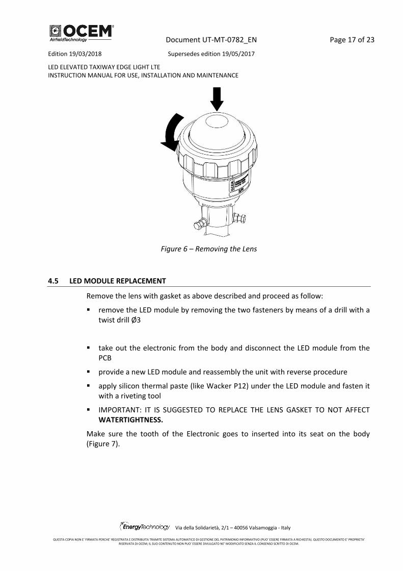
Unscrew the lens locking ring and remove the broken lens with the relevant gasket
from the fixture body.
In order to removal the lens, press down the lens with the palm of one hand and,
with the other hand, unscrew the locking ring (Figure 6).
Place a new gasket on the body.
Set the new lens on the body.
Hand tighten the locking ring.
Document UT-MT-0782_EN Page 17 of 23
Edition 19/03/2018 Supersedes edition 19/05/2017
LED ELEVATED TAXIWAY EDGE LIGHT LTE
INSTRUCTION MANUAL FOR USE, INSTALLATION AND MAINTENANCE
Via della Solidarietà, 2/1 – 40056 Valsamoggia - Italy
QUESTA COPIA NON E’ FIRMATA PERCHE’ REGISTRATA E DISTRIBUITA TRAMITE SISTEMA AUTOMATICO DI GESTIONE DEL PATRIMONIO INFORMATIVO (PUO’ ESSERE FIRMATA A RICHIESTA). QUESTO DOCUMENTO E’ PROPRIETA’
RISERVATA DI OCEM; IL SUO CONTENUTO NON PUO’ ESSERE DIVULGATO NE’ MODIFICATO SENZA IL CONSENSO SCRITTO DI OCEM.
Figure 6 – Removing the Lens
4.5 LED MODULE REPLACEMENT
Remove the lens with gasket as above described and proceed as follow:
� remove the LED module by removing the two fasteners by means of a drill with a
twist drill Ø3
� take out the electronic from the body and disconnect the LED module from the
PCB
� provide a new LED module and reassembly the unit with reverse procedure
� apply silicon thermal paste (like Wacker P12) under the LED module and fasten it
with a riveting tool
� IMPORTANT: IT IS SUGGESTED TO REPLACE THE LENS GASKET TO NOT AFFECT
WATERTIGHTNESS.
Make sure the tooth of the Electronic goes to inserted into its seat on the body
(Figure 7).

Document UT-MT-0782_EN Page 18 of 23
Edition 19/03/2018 Supersedes edition 19/05/2017
LED ELEVATED TAXIWAY EDGE LIGHT LTE
INSTRUCTION MANUAL FOR USE, INSTALLATION AND MAINTENANCE
Via della Solidarietà, 2/1 – 40056 Valsamoggia - Italy
QUESTA COPIA NON E’ FIRMATA PERCHE’ REGISTRATA E DISTRIBUITA TRAMITE SISTEMA AUTOMATICO DI GESTIONE DEL PATRIMONIO INFORMATIVO (PUO’ ESSERE FIRMATA A RICHIESTA). QUESTO DOCUMENTO E’ PROPRIETA’
RISERVATA DI OCEM; IL SUO CONTENUTO NON PUO’ ESSERE DIVULGATO NE’ MODIFICATO SENZA IL CONSENSO SCRITTO DI OCEM.
1. Electronic
2. Main body
Figure 7 – Reassembly the Light Unit
4.6 ELECTRONIC REPLACEMENT
Remove the lens with gasket as above described and proceed as follow:
� take out the electronic from the body and disconnect the PCB from cable lead
with plug and from the LED module
� remove the LED module by removing the two fasteners by means of a drill with a
twist drill Ø3
� provide a new electronic and reassembly the unit with reverse procedure
� apply silicon thermal paste (like Wacker P12) under the LED module and fasten it
with a riveting tool
IMPORTANT: IT IS SUGGESTED TO REPLACE THE LENS GASKET TO NOT AFFECT
WATERTIGHTNESS.
4.7 BREAKABLE COUPLING REPLACEMENT
Unscrew the lower threaded section of broken breakable coupling from the pipe
elbow (or base plate), cut the grounding wire, disconnect the light plug from the
secondary receptacle and remove the threaded section.
Remove the upper section of the broken breakable coupling from the 1-inch pipe by
releasing the setscrew.
If damaged, replace the 1-inch tube too. To make free the tube, release the setscrew
on the main body.

Document UT-MT-0782_EN Page 19 of 23
Edition 19/03/2018 Supersedes edition 19/05/2017
LED ELEVATED TAXIWAY EDGE LIGHT LTE
INSTRUCTION MANUAL FOR USE, INSTALLATION AND MAINTENANCE
Via della Solidarietà, 2/1 – 40056 Valsamoggia - Italy
QUESTA COPIA NON E’ FIRMATA PERCHE’ REGISTRATA E DISTRIBUITA TRAMITE SISTEMA AUTOMATICO DI GESTIONE DEL PATRIMONIO INFORMATIVO (PUO’ ESSERE FIRMATA A RICHIESTA). QUESTO DOCUMENTO E’ PROPRIETA’
RISERVATA DI OCEM; IL SUO CONTENUTO NON PUO’ ESSERE DIVULGATO NE’ MODIFICATO SENZA IL CONSENSO SCRITTO DI OCEM.
Provide a new breakable coupling and, if required, a new 1-inch tube.
Reassembly the unit by following the installation steps.
4.8 CABLE LEAD WITH PLUG
4.8.1 Removing the cable lead with plug
The replacement of the cable lead requires the fixture completely disassembled;
follow the procedures above described to replace the power supply/control PCB, to
replace the breakable coupling and the 1-inch tube.
Unscrew the grounding screw inside the body to make free the grounding cable.
Remove the cable gland from the outside of the fixture body using a double ended
deep offset ring wrench CH 20; pull out the damaged cable lead and/or the grounding
wire from the sealing insert.
4.8.2 Installing the new cable lead with plug
Replace the cable gland if damaged.
Insert a new cable lead and a new grounding wire (if necessary) into the sealing insert
at approx 8 cm from the free extremity of the cable lead. Take care that the
grounding wire end with eyelet terminal be at 3-4 cm from the cable gland.
Place the sealing insert into the relevant cable gland seat and tighten it using a
double ended deep offset ring wrench CH 20.
Reassembly with reverse procedure.
4.9 ARCTIC KIT REPLACEMENT
4.9.1 Thermostat
Remove the lens with gasket as above described.
Disconnect the thermostat from the cable lead with plug, from the PCB and from the
heater (Figure 8), unscrew the two screws HSCH M3x6.
Document UT-MT-0782_EN Page 20 of 23
Edition 19/03/2018 Supersedes edition 19/05/2017
LED ELEVATED TAXIWAY EDGE LIGHT LTE
INSTRUCTION MANUAL FOR USE, INSTALLATION AND MAINTENANCE
Via della Solidarietà, 2/1 – 40056 Valsamoggia - Italy
QUESTA COPIA NON E’ FIRMATA PERCHE’ REGISTRATA E DISTRIBUITA TRAMITE SISTEMA AUTOMATICO DI GESTIONE DEL PATRIMONIO INFORMATIVO (PUO’ ESSERE FIRMATA A RICHIESTA). QUESTO DOCUMENTO E’ PROPRIETA’
RISERVATA DI OCEM; IL SUO CONTENUTO NON PUO’ ESSERE DIVULGATO NE’ MODIFICATO SENZA IL CONSENSO SCRITTO DI OCEM.
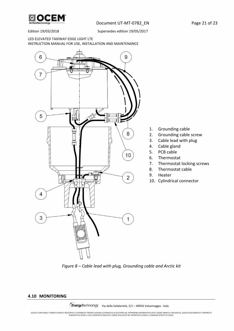
Take a new thermostat with soldered cable, tighten the two screws with tightening
torque 0.6 Nm, and join the wires through the cylindrical butt connectors as shown in
the diagram of Figure 8.
Carefully insert the wires of the heater, those of the thermostat and those of the LED
board into the seat on the side of the electronic to avoid damage to the cables when
you insert the electronic into the main body.
4.9.2 Heater
Proceed as described in the preceding paragraph.
Positional the new heater in the groove of the plastic ring. Position the ring on the
electronic so that the heater comes into contact with the lens and the cables can
move trought the seat on the side of the electronic.
Reassemble the fixture as described above.
Document UT-MT-0782_EN Page 21 of 23
Edition 19/03/2018 Supersedes edition 19/05/2017
LED ELEVATED TAXIWAY EDGE LIGHT LTE
INSTRUCTION MANUAL FOR USE, INSTALLATION AND MAINTENANCE
Via della Solidarietà, 2/1 – 40056 Valsamoggia - Italy
QUESTA COPIA NON E’ FIRMATA PERCHE’ REGISTRATA E DISTRIBUITA TRAMITE SISTEMA AUTOMATICO DI GESTIONE DEL PATRIMONIO INFORMATIVO (PUO’ ESSERE FIRMATA A RICHIESTA). QUESTO DOCUMENTO E’ PROPRIETA’
RISERVATA DI OCEM; IL SUO CONTENUTO NON PUO’ ESSERE DIVULGATO NE’ MODIFICATO SENZA IL CONSENSO SCRITTO DI OCEM.
1. Grounding cable
2. Grounding cable screw
3. Cable lead with plug
4. Cable gland
5. PCB cable
6. Thermostat
7. Thermostat locking screws
8. Thermostat cable
9. Heater
10. Cylindrical connector
Figure 8 – Cable lead with plug, Grounding cable and Arctic kit
4.10 MONITORING
Document UT-MT-0782_EN Page 22 of 23
Edition 19/03/2018 Supersedes edition 19/05/2017
LED ELEVATED TAXIWAY EDGE LIGHT LTE
INSTRUCTION MANUAL FOR USE, INSTALLATION AND MAINTENANCE
Via della Solidarietà, 2/1 – 40056 Valsamoggia - Italy
QUESTA COPIA NON E’ FIRMATA PERCHE’ REGISTRATA E DISTRIBUITA TRAMITE SISTEMA AUTOMATICO DI GESTIONE DEL PATRIMONIO INFORMATIVO (PUO’ ESSERE FIRMATA A RICHIESTA). QUESTO DOCUMENTO E’ PROPRIETA’
RISERVATA DI OCEM; IL SUO CONTENUTO NON PUO’ ESSERE DIVULGATO NE’ MODIFICATO SENZA IL CONSENSO SCRITTO DI OCEM.
The fixtures can be provided with the option of monitoring. This device allows to
show at the constant current regulator as if the fixture circuit was open when a LED
burns out. The fixture thus acts as a traditional lamp fixture.
When the fixture has a bad operation, the internal monitoring device disconnects
definitively the fixture from the series circuit; after this operation to restore the
normal operation of the fixture it’s necessary to replace the LED board and unlock
the monitoring device. For this operation it is necessary to follow these steps:
� remove the fixture from the base and open it following instructions of “Removing
and Opening the Light Unit”
� replace the LED module following instructions of “LED Module Replacement”
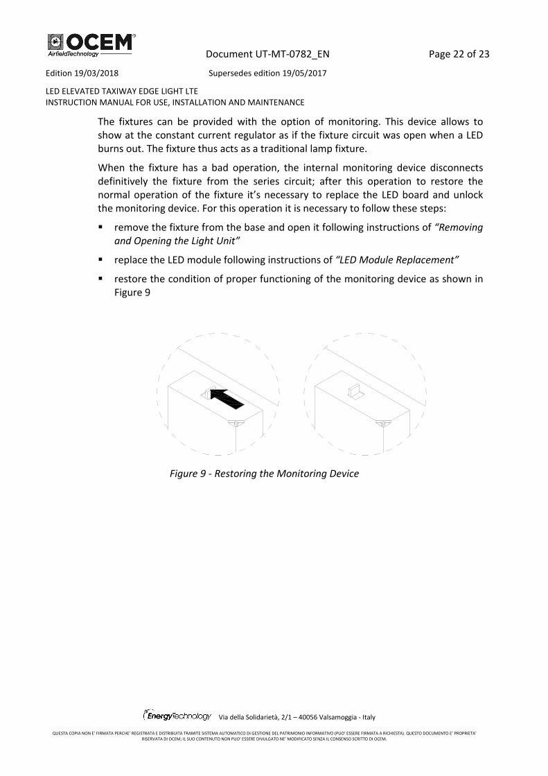
� restore the condition of proper functioning of the monitoring device as shown in
Figure 9
Figure 9 - Restoring the Monitoring Device
Document UT-MT-0782_EN Page 23 of 23
Edition 19/03/2018 Supersedes edition 19/05/2017
LED ELEVATED TAXIWAY EDGE LIGHT LTE
INSTRUCTION MANUAL FOR USE, INSTALLATION AND MAINTENANCE
Via della Solidarietà, 2/1 – 40056 Valsamoggia - Italy
QUESTA COPIA NON E’ FIRMATA PERCHE’ REGISTRATA E DISTRIBUITA TRAMITE SISTEMA AUTOMATICO DI GESTIONE DEL PATRIMONIO INFORMATIVO (PUO’ ESSERE FIRMATA A RICHIESTA). QUESTO DOCUMENTO E’ PROPRIETA’
RISERVATA DI OCEM; IL SUO CONTENUTO NON PUO’ ESSERE DIVULGATO NE’ MODIFICATO SENZA IL CONSENSO SCRITTO DI OCEM.
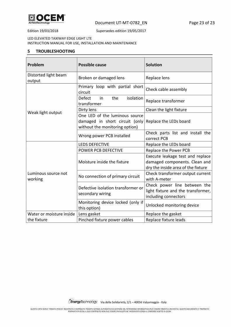
5 TROUBLESHOOTING
Problem Possible cause Solution
Distorted light beam
output Broken or damaged lens Replace lens
Weak light output
Primary loop with partial short
circuit Check cable assembly
Defect in the isolation
transformer Replace transformer
Dirty lens Clean the light fixture
One LED of the luminous source
damaged in short circuit (only
without the monitoring option)
Replace the LEDs board
Wrong power PCB installed Check parts list and install the
correct PCB
Luminous source not
working
LEDS DEFECTIVE Replace the LEDs board
POWER PCB DEFECTIVE Replace the Power PCB
Moisture inside the fixture
Execute leakage test and replace
damaged components. Clean and
dry the inside area of the fixture
No connection of primary circuit Check transformer output current
with A-meter
Defective isolation transformer or
secondary wiring
Check power line between the
light fixture and the transformer,
including connectors
Monitoring device locked (only if
this option) Unlocked monitoring device
Water or moisture inside
the fixture
Lens gasket Replace the gasket
Pinched fixture power cables Replace fixture leads