lectures notes of strength of materials
TRANSCRIPT

1
Modern University For Information and Technology
Electrical Engineering Department
Lectures Notes of Strength of Materials
BIO 207
Prepared By Dr: Shaimaa Mostafa
(First Edition 2021)

1
Vision
The vision of the Faculty of Engineering at MTI university is to be
a center of excellence in engineering education and scientific
research in national and global regions. The Faculty of Engineering
aims to prepare graduates meet the needs of society and contribute
to sustainable development.
Mission
The Faculty of Engineering MTI university aims to develop
distinguished graduates that can enhance in the scientific and
professional status, through the various programs which fulfill the
needs of local and regional markets. The Faculty of Engineering
hopes to provide the graduates a highly academic level to keep up
the global developments.

2
COURSE OUTLINE
Chapter Title Page
Chapter (1): Introduction – Concept of Stress …………………...3
Chapter (2): Axial Loading: Shearing Stress - Bearing Stress …..10
Chapter (3): Stress and Strain – Axial Loading…………………..21
Chapter (4): Composite/Compound Bars ………………………...28
Chapter (5): Torsion………………………………….……..........37
Chapter (6): Beams under concentrated or distributed loads……..48
Chapter (7): Strain Energy and Resilience………...……………..59
Sheets…………………………………………………………….78
References:
[1] Mechanics of Materials, Ferdinand P. Beer, E. Russell Johnston, Jr., John
T. DeWolf, David F. Mazurek, Seventh Edition, 2015.

3
Chapter (1)
Introduction – Concept of Stress
Contents
1.1. Concept of Stress
1.2. Review of Statics
1.3. Component Free-Body Diagram
1.4. Method of Joints
1.5. Stress Analysis
1.6. Stresses in the Members of a Structure
1.6.1. Axial Loading: Normal Stress

4
1.1. Concept of Stress
The main objective of the study of mechanics of materials is to
provide the future engineer with the means of analyzing and
designing various machines and load bearing structures.
Both the analysis and design of a given structure involve the
determination of stresses and deformations. This chapter is devoted
to the concept of stress.
1.2. Review of Statics
The structure is designed to support
a 30 kN load. Perform a static
analysis to determine the internal
force in each structural member
and the reaction forces at the
supports.
1.3. Component Free-Body Diagram

5
Conditions for static equilibrium
Consider a free-body diagram for the boom
substitute into the structure equilibrium
equation:
Cy = 30kN
Results:
A = 40kN → Cx = 40kN ← Cy = 30kN ↑
1.4. Method of Joints
The members are subjected to only two forces which are applied at
member ends. Joints must satisfy the conditions for static
equilibrium which may be expressed in the form of a force triangle:

6
1.5. Stress Analysis
Can the structure safely support the 30 kN load?
From a statics analysis
FAB = 40 kN (compression)
FBC = 50 kN (tension)
At any section through member BC
(dBC = 20 mm), the internal force is 50
kN with a force intensity or stress of:
From the material properties for steel, the allowable stress is: σ all
= 165MPa
Conclusion: the strength of member BC is adequate.
1.6. Stresses in the Members of A Structure
1.6.1. Axial Loading: Normal Stress
The first and necessary step in the analysis of a structure is to find
forces in individual members.
The normal stress in a member of cross-sectional area A subjected
to an axial load P is obtained by:

7
Axial force represents the resultant force and uniform stress distribution
Solved Example (1):
Two solid cylindrical rods AB and BC are welded
together at B and loaded as shown. Knowing that the
average normal stress must not exceed 175 MPa in rod
AB and 150 MPa in rod BC, determine the smallest
allowable values of d1 and d2.

8
Solution:
Solved Example (2):
Two steel plates are to be held together by means of 16-mm diameter
high-strength steel bolts fitting snugly inside cylindrical brass
spacers. Knowing that the average normal stress must not exceed
200 MPa in the bolts and 130 MPa in the spacers, determine the
outer diameter of the spacers that yields the most economical and
safe design.

9
Solution:
The upper plate is pulled down by the tensile force Pb of the bolt
The spacer pushes that plate upward with a compressive force Ps
To satisfy equilibrium: Pb = Ps
Solved Example (3):
A cast iron link, as shown in the figure is required to transmit a
steady tensile load of 45 kN. Find the tensile stress induced in the
link material at sections A-A and B-B.

10
Solution:

11
Chapter (2)
Axial Loading
Contents
2.1. Shearing Stress
2.2. Bearing Stress
2.3. Factor of Safety
Solved Examples
Problems

12
2.1. Shearing Stress
Shearing stress is obtained when an equal and transverse forces P
and P’ are applied to a member AB. Normal stress caused by forces
perpendicular to the area on which it act, while shear stress caused
by forces parallel to the area resisting the forces.
Bolt subject to single shear
average shearing stress in case of single shear:
average shearing stress in case of double shear:

13
Solved Example (1)
Compute the shearing stress in the pin at
B for the member supported as shown.
The pin diameter is 20 mm.
Solution:

14
Solved Example (2)
Three steel bolts are to be used to attach the steel
plate shown to a wooden beam. Knowing that the
plate will support a 110-kN load, that the shearing
stress for the steel used is 107 MPa, determine the
required diameter of the bolts.
Solution:
Shear stress τ = 107 MPa
F
3A=
P
3π
4d2
d = √4p
3πτ
d = √4×110×1000
3π×107 = 20.8 mm
Solved Example (3)
A pull of 80 kN is transmitted from a bar X to the bar Y through a
pin. If the maximum permissible tensile stress in the bars is 100
N/mm2 and the permissible shear stress in the pin is 80 N/ mm2, find
the diameter of bars and of the pin.

15
Solution:
Given: P = 80 KN = 80×103 N
σt = 100 MPa
τ = 80 MPa
Diameter of the bar
16
Diameter of the pin
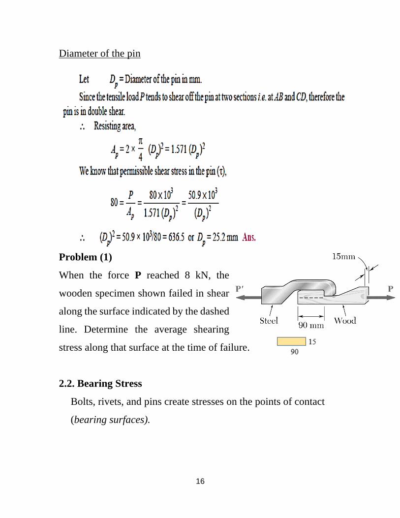
Problem (1)
When the force P reached 8 kN, the
wooden specimen shown failed in shear
along the surface indicated by the dashed
line. Determine the average shearing
stress along that surface at the time of failure.
2.2. Bearing Stress
Bolts, rivets, and pins create stresses on the points of contact
(bearing surfaces).

17
Bearing stress obtained by:
Solved Example (4)
A 6-mm diameter pin is used at the connection c of the pedal shown.
knowing that P = 500 N, determine: (a) the average shearing stress
in the pin, (b) the nominal bearing stress in the pedal C. (c) the
nominal bearing stress in each support bracket at C.
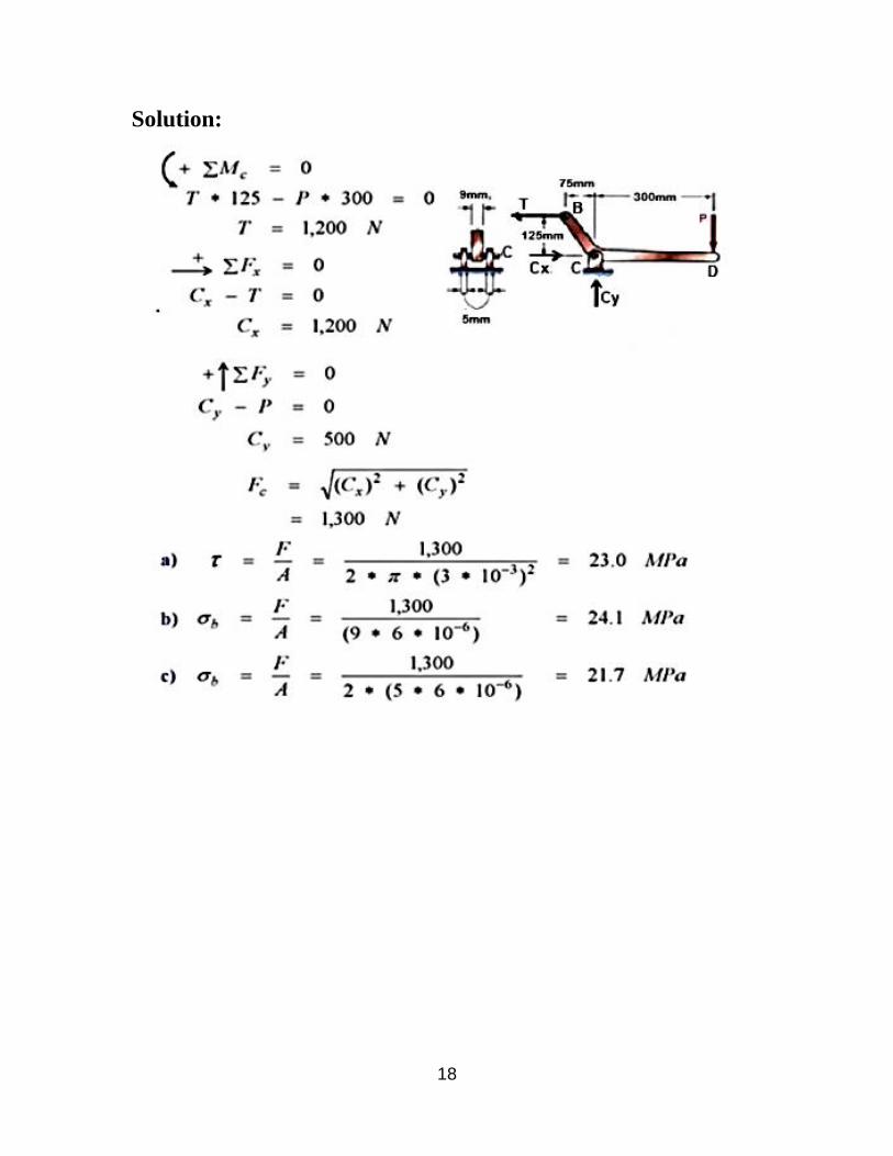
18
Solution:

19
Solved Example (5)
An axial load P is supported by a short
W 8 × 40 column of cross-sectional
area A = 11.7 in.2 and is distributed to
a concrete foundation by a square
plate as shown. Knowing that the
average normal stress in the column
must not exceed 30 ksi and that the
bearing stress on the concrete
foundation must not exceed 3 ksi, determine the side a of the plate
that will provide the most economical and safe design.
Solution:

20
2.3. Factor of Safety
The maximum load that a structural member or a machine
component will be allowed to carry is smaller than the ultimate
load. This smaller load is the allowable load.
The ratio of the ultimate load to the allowable load is used to
define the factor of safety:
Solved Example (6)
Link AB is to be made of a steel for
which the ultimate normal stress is
450 MPa. Determine the cross-
sectional area for AB for which the
factor of safety will be 3.5. Assume
that the link will be adequately
reinforced around the pins at A and B.

21
Solution:
Problem (1)
Two loads are applied to the bracket BCD
as shown:
(a) Knowing that the control rod AB is to
be made of a steel having an ultimate
normal stress of 600 MPa, determine the
diameter of the rod for which the factor of
safety is 3.3.
(b) The pin at C is to be made of a steel
having an ultimate shearing stress of 350
MPa. Determine the diameter of the pin C
for which the factor of safety is also 3.3.
22
(c) Determine the required thickness of the bracket supports at C,
knowing that the allowable bearing stress of the steel used is 300
MPa.
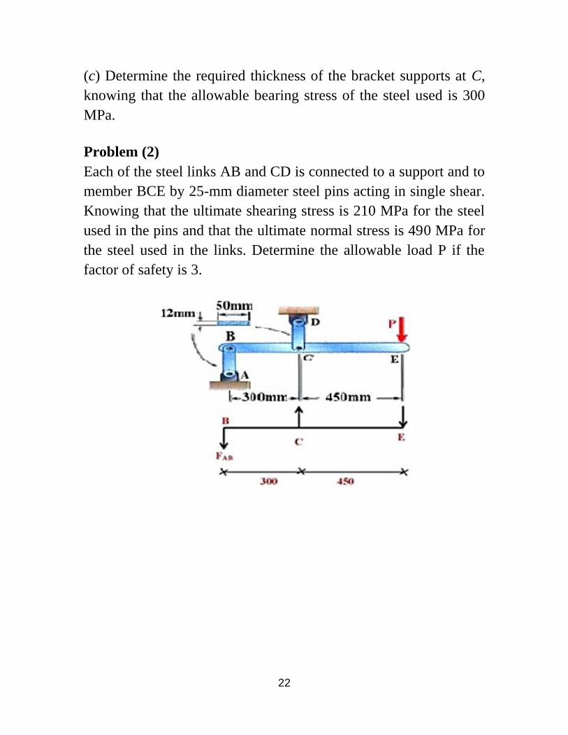
Problem (2)
Each of the steel links AB and CD is connected to a support and to
member BCE by 25-mm diameter steel pins acting in single shear.
Knowing that the ultimate shearing stress is 210 MPa for the steel
used in the pins and that the ultimate normal stress is 490 MPa for
the steel used in the links. Determine the allowable load P if the
factor of safety is 3.

23
Chapter (3)
Stress and Strain – Axial Loading
Contents
3.1. Stress & Strain: Axial Loading
3.2. Normal Strain
3.3. Stress-Strain Test
3.4. Stress-Strain Diagram: Ductile and Brittle Materials
3.5. Hooke’s Law: Modulus of Elasticity
3.6. Deformations Under Axial Loading

24
3.1. Stress & Strain: Axial Loading
Suitability of a structure or machine may depend on the
deformations in the structure as well as the stresses induced under
loading. This chapter concerned with deformation of a structural
member under axial loading.
3.2. Normal Strain
Consider a homogeneous rod BC of length L and
uniform cross section of area A subjected to a centric
axial load P, the normal stress relation become:
The normal strain is:
Where: σ: normal stress
P: applied load
A: cross-sectional area of the rod
ε: normal strain
δ: deformation of the rod (increase in length)
L: length of the rod
25
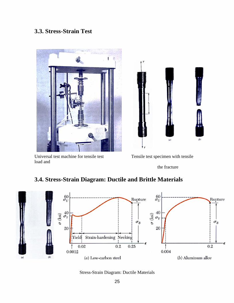
3.3. Stress-Strain Test
Universal test machine for tensile test Tensile test specimen with tensile
load and
the fracture
3.4. Stress-Strain Diagram: Ductile and Brittle Materials
Stress-Strain Diagram: Ductile Materials

26
Stress-Strain Diagram: Brittle Materials

27
3.5. Hooke’s Law: Modulus of Elasticity
The deformations of a structural member such as a
rod, bar, or plate is due to axial loading applied to
the structure.
Consider a homogeneous rod BC of length L and
uniform cross section of area A subjected to a
centric axial load P, from Hooke’s Law the
Modulus of Elasticity or Youngs Modulus equal to:
E = 𝜎
= 𝑃𝐿
𝐴𝛿 (
𝑁.𝑚𝑚
𝑚𝑚2.𝑚𝑚 = MPa)
3.6. Deformations Under Axial Loading
From Hooke’s Law the deformation become:
δ = 𝑃𝐿
𝐴𝐸 (mm)
Where:
δ: is the deformation of the member (increase in length)
P: is the applied load
E: is the modulus of elasticity
With variations in loading, cross-section or material properties:

28
Solved Example (1)
A 25 mm diameter bar is subjected to an axial
tensile load of 100 kN. Under the action of this
load a 200 mm gauge length is found to extend
0.19×10⁻³ mm. Determine the modulus of
elasticity for the bar material.
Solution:
Solved Example (2)
The assembly consists of three titanium (Ti-6A1-4V) rods and a
rigid bar AC. The cross-sectional area of each rod is given in the
figure. If a force of 6 kip is applied to the ring F, determine the
horizontal displacement of point F if E = 17.4×10³ psi.

29
Solution:

30
Problem (1)
The A-36 steel rod is subjected to the loading shown. If the diameter
of the rod is 8 mm, determine the displacement of its end D.
Knowing that the modulus of elasticity E= 200 Gpa.

31
Chapter (4)
Composite and Compound Bars
Contents
4.1. Non-uniform Bars
4.2. Composite/Compound Bars
4.3. Thermal Stresses
4.4. Types Of Installations and Strength

32
4.1. Non-uniform Bars
Bars with cross-sections varying in steps are called non-uniform
bars. A typical bar with cross-sections varying in steps and subjected
to axial load is as shown in the figure. Let the length of three portions
be L1, L2 and L3 and the respective cross-sectional areas of the
portion be A1, A2, A3 and E be the Young’s modulus of the material
and P be the applied axial load. The lower figure shows the forces
acting on the cross-sections of the three portions.

33
Hence total change in length of the bar:
δt = δ1+ δ2+ δ3 = 𝑃𝐿1
𝐴1𝐸+
𝑃𝐿2
𝐴2𝐸 +
𝑃𝐿3
𝐴3𝐸
Solved Example (1)
The bar shown in the Figure is tested in universal testing machine.
It is observed that at a load of 40 kN the total extension of the bar is
0.280 mm. Determine the Young’s modulus of the material.
Solution:
Extension of portion 1: δ1 =
Extension of portion 2: δ2 =
Extension of portion 3: δ3 =

34
Problem (1)
Determine the deformation of
deflections. the steel rod shown under
the given loads.
Problem (2)
The specimen shown has been cut
from a 0.25 in. thick sheet of vinyl (E
= 0.45×10⁶ psi) and is subjected to a
350-lb tensile load. Determine (a)
deformation of its central portion BC.
(b) the total deformation of the specimen
4.2. Composite/Compound Bars
Bars made up of two or more materials are called
composite/compound bars. They may have same length or different

35
lengths as shown in the figure. The ends of different materials of the
bar are held together under loaded conditions.
Consider a member with two materials. Let the load shared by
material 1 be P1 and that by material 2 be P2. Then:
i. From equation of equilibrium of the forces, we get:
P = P1 + P2
ii. Since the ends are held securely, we get δ1 = δ2 where δ1 and
δ2 are the extension of the bars of material 1 and 2 respectively
i.e.
Using this equation, P1 and P2 can be found uniquely.
36
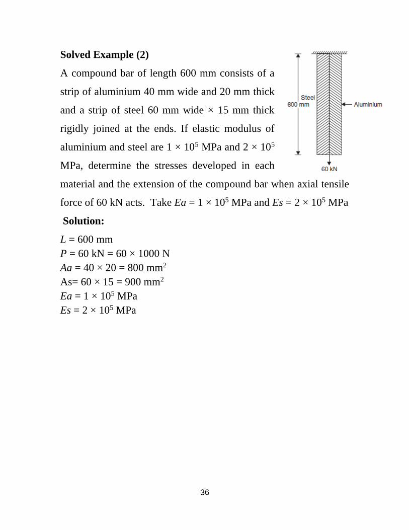
Solved Example (2)
A compound bar of length 600 mm consists of a
strip of aluminium 40 mm wide and 20 mm thick
and a strip of steel 60 mm wide × 15 mm thick
rigidly joined at the ends. If elastic modulus of
aluminium and steel are 1 × 10⁵ MPa and 2 × 10⁵
MPa, determine the stresses developed in each
material and the extension of the compound bar when axial tensile
force of 60 kN acts. Take Ea = 1 × 10⁵ MPa and Es = 2 × 10⁵ MPa
Solution:
L = 600 mm
P = 60 kN = 60 × 1000 N
Aa = 40 × 20 = 800 mm2
As= 60 × 15 = 900 mm2
Ea = 1 × 10⁵ MPa
Es = 2 × 10⁵ MPa

37

38
Solved Example (3)
A compound bar consists of a circular rod of steel
of 25 mm diameter rigidly fixed into a copper tube
of internal diameter 25 mm and external diameter
40 mm. If the compound bar is subjected to a load
of 120 kN, find the stresses developed in the two materials.
Solution:

39
4.3. Thermal Stresses
Every material expands when temperature rises and
contracts when temperature falls. It is established
experimentally that the change in length δ is directly
proportional to the length of the member L and
change in temperature (ΔT). Thus
δ ∝ (ΔT) L
δ = α (ΔT) L
The constant of proportionality α is called
coefficient of thermal expansion and is defined
as change in unit length of material due to unit
change in temperature.
the support force P develops to keep it at the
original position. Magnitude of this force is such that contraction is
equal to free expansion:

40
𝑃𝐿1
𝐴1𝐸 = α (ΔT) L
σ = E α (ΔT) where, σ is the stress in this case.
Solved Example (4)
The composite bar shown is rigidly fixed
at the ends A and B. Determine the
reaction developed at ends when the
temperature is raised by 18°C. Knowing:
Ea = 70 kN/mm2
Es = 200 kN/mm2
αa = 11 × 10–6/°C
αs = 12 × 10–6/°C
Solution:
Free expansion = α (ΔT) La + α (ΔT) Ls =
= (11 × 10–6 × 18 × 1500) + (12 × 10–6 × 18 × 3000) =
0.945 mm
δ = (𝑃𝐿
𝐴𝐸)𝑎 + (
𝑃𝐿
𝐴𝐸 ) 𝑠

41
Chapter (5)
Torsion
Contents
5.1. Torsional Loads on Circular Shafts
5.2. The Shear Stress Formula
5.3. Angle of Twist in Elastic Range
5.4. Power Transmitted by a Shaft
5.5. Stress in Rotating Arms (Fatigue)

42
5.1. Torsional Loads on Circular Shafts
Torsion interested in stresses and strains of circular shafts subjected
to twisting couples or torques. Turbine exerts torque T on the shaft,
then the shaft transmits the torque to the generator. Generator
creates an equal and opposite torque T’. So, shaft subjected to equal
and opposite torque, producing shear stress τ.
5.2. The Shear Stress Formula
Torque applied to shaft produces shearing stresses
on the faces perpendicular to the axis. The
shearing stress results are known as:
τ = 𝑇⋅𝐶
𝐼𝑝
Where,
τ: shearing stress
T: twisting moment (torque)

43
C: shaft radius
Ip: polar moment of area (second moment)
Ip = 𝜋
32𝑑4 =
𝜋
2𝐶4 (solid shaft)
Ip = 𝜋
32(𝑑0
4 − dⅈ4) (Tubular shaft)
➢ Therefore, total torque transmitted by a circular solid
shaft:
τmax = 𝑇⋅𝐶
𝐼𝑝 =
𝑇⋅(𝑑
2)
𝜋
32𝑑4
= 16 𝑇
𝜋𝑑3 solid shaft
τmax = 16 𝑇𝐷
𝜋(𝐷4− 𝑑4
) hollow shaft
Solved Example (1)
The solid rod AB has a diameter dAB 60
mm and is made of a steel for which the
allowable shearing stress is 85 MPa. The
pipe CD, which has an outer diameter of 90
mm and a wall thickness of 6 mm, is made
of an aluminum for which the allowable
shearing stress is 54 MPa. Determine the
largest torque T that can be applied at A.

44
Solution:
Rod AB:
τ = 85 MPa C = 30 mm
Ip = 𝜋
2𝐶4 =
𝜋
2(30)4 = 1.3×106 mm4
T = τ⋅𝐼𝑝
𝐶 =
85 ×1.3 × 106
30 = 3.6×10⁶ N.mm
Pipe CD:
τ = 54 MPa Co = 45 mm
Ci = Co - t = 45 – 6 = 39 mm
Ip = 𝜋
2(𝐶0
4 − Cⅈ4) = 𝜋
2(454 − 394) =2.8×106 mm4
T = τ⋅𝐼𝑝
𝐶 =
54 ∗1.3 * 106
45 = 3.3×10⁶ N.mm
Allowable torque is the smaller value: T = 3.3×10⁶ N.mm
Problem (1)
Determine the torque T that causes a
maximum shearing stress of 70 MPa in the
cylindrical steel shaft shown.
Problem (2)
A solid steel shaft is to transmit a torque of 10 KN.m. If the shearing
stress is not exceed 45 MPa, find the minimum diameter of the shaft.

45
5.3. Angle of Twist in Elastic Range
the angle of twist of the shaft is
proportional
to the applied torque and to the shaft
length.
φ ∝ T φ ∝ L
𝜙 =𝑇 ⋅ 𝐿
𝐼𝑝 ⋅ 𝐺 (𝑟𝑎𝑑)
Where,
𝜙 : angle of twist
T: twisting moment (torque)
L: shaft length
Ip: polar moment of area
G: modulus of rigidity of the
shaft material
Solved Example (2)
The torques shown are exerted on pulleys B, C, and D. Knowing
that the shaft is made of steel (G = 27 GPa), determine the angle of
twist between (a) B and C, (b) B and D.

46
Solution:
Shaft BC:
C = 15 mm
Ip = 𝜋
2C4 =
𝜋
2 (15)4 = 79.5×103 mm4
LBC = 800 mm
T BC = + 400×103 N.mm
G = 27×103 MPa
φBC =𝑇𝐵𝐶⋅𝐿𝐵𝐶
𝐼𝑝⋅𝐺
φBC = 400×103 ×800
79.5×103×27×103 = 0.14 rad×180/π = 8.5
o
(b) Shaft CD:
C = 18 mm
Ip = 𝜋
2𝐶4 =
𝜋
2(18)4 = 164.8×103 mm4
LCD = 1000 mm

47
T CD = - 500×103 N.mm
G = 27×103 MPa
φCD =𝑇𝐶𝐷⋅𝐿𝐶𝐷
𝐼𝑝⋅𝐺
φCD =− 500×103×1000
164.8×103×27×103 = - 0.11 rad
φBD = φBC + φCD = 0.14 - 0.11 = 0.03 rad
φBD = 0.03×180/ π = 1.7o
Problem (3)
A steel shaft 3 ft long that has a diameter of 4 in is subjected to a
torque of 15 kip·ft. Determine the maximum shearing stress and the
angle of twist. Use G = 12 × 106 psi
5.4. Power Transmitted by a Shaft

48
Let us consider that N is the R.P.M of the shaft and ω is the angular
velocity of the shaft. We have already secured here the torque
transmitted by circular solid shaft and it is mentioned above. Now
we will find here the expression for power transmitted by solid
circular shaft as mentioned here.
Power = work done in KN.m/second
Power = force × distance = T× ω = T×2πN
Solved Example (3)
A hollow shaft is to transmit 200 kW at 80 r.p.m. If the shear stress
is not to exceed 60 MPa and internal diameter is 0.6 of the external
diameter, find the diameters of the shaft.
Solution:
Given : Power (P) = 200 kW Speed of shaft (N) = 80 r.p.m.
Maximum shear stress (τ) = 60 MPa = 60 N/mm2
Inner diameter of the shaft (d) = 0.6D (D is the outer
diameter).

49
Problem (4)
A steel marine propeller shaft 14 in. in diameter and 18 ft long is
used to transmit 5000 hp at 189 rpm. If G = 12 × 106 psi, determine
the maximum shearing stress.
5.5. Stress in Rotating Arms (Fatigue)
When a metal is subjected to repeated cycles of stress or strain, it
causes its structure to break down, ultimately leading to fracture.
This behavior is called fatigue, and it is usually responsible for a
large percentage of failures in connecting rods and crankshafts of
engines; steam or gas turbine blades; connections or supports for

50
bridges, railroad wheels, and axles; and other parts subjected to
cyclic loading. Fatigue properties are shown on S-N diagrams.
Solved Example (4)
The fatigue data for a brass alloy are given
as follows:
(a) Make an S–N plot (stress amplitude
versus logarithm cycles to failure) using
these data.
(b) Determine the fatigue strength at 5×10⁵
cycles.
(c) Determine the fatigue life for 200 MPa.

51
Solution:

52
Chapter (6)
Beams under concentrated or distributed loads
Contents
6.1. Pure Bending
6.2. Common Load Types for Beams
6.3. Centroid and Moment of Inertia
6.4. Parallel Axes Theorem of Moment of Inertia
6.5. Stress Due to Bending
6.6. Bending Stress in Straight Beams

53
6.1. Pure Bending
Pure Bending: Prismatic members subjected to equal and opposite
couples
acting in the same longitudinal plane
6.2. Common Load Types for Beams
Several common loading types for beams and frames are shown
in the figure:

54
6.3. Centroid and Moment of Inertia
Centroid (for any object in dimensional space): is the mean position
of all the points in all of the coordinates directions, it can be
determined by:

55
Centroid (Center of mass): �̅� =∑ 𝑥⋅𝐴
∑ 𝐴
Centroid (Center of mass): �̅� =∑ 𝑌⋅𝐴
∑ 𝐴
Moment of inertia of the rectangular cross
section:
𝐼𝑥 =1
12𝑏ℎ3 𝐼𝑦 =
1
12ℎ𝑏3
Moment of inertia for circle: I = (π/64)d4 = (π/4)r4
6.4. Parallel Axes Theorem of Moment of
Inertia
Symmetric around y, get Iy: 𝐼𝑦 =1
12ℎ𝑏3
If symmetric around y we get Ix using
Parallel axes theory:
Ix = Σ [Ix + A(Y- �̅�)]= [Ix1 + A1(Y1- �̅�)2]+ [Ix2 + A2(Y2- �̅�)2]
Solved Example (1)
Determine the moment of inertia of the shown figure:

56
Solution:
For rectangle cross sectional area
Solved Example (2)
Calculate the location of the section centroid
and moment of inertia of the shown bar.
Solution:
location of the section centroid:
and moment of inertia of the shown bar, symmetric around x and y:
centroid �̅� and �̅� lies in the midpoint of the bar.
�̅� = 50 mm �̅� = 40 mm
Moment of inertia:
For circle I = (π/64)d4 = (π/4)r4

57
6.5. Stress Due to Bending
Formula to find the maximum tensile and compressive normal
stresses due to bending:
σm = 𝑀
𝐼⋅ 𝑦
σm: max bending stress
M: Bending moment
I: moment of inertia
y: section centroid
Solved Example (3)
Knowing that the couple shown acts in a vertical plane, determine
the: stress at (a) point A, (b) point B.

58
Solution:
Solved Example (4)
Based on the given cross section geometry, calculate maximum
tensile and compressive normal stresses at point A and point B.
Solution:
Iy =1
12hb3 = (
1
12)(20)(903) + (
1
12)(40)(303)
Iy = 1305×103 mm4

59
𝑌 =(𝟐𝟎×𝟗𝟎)(𝟓𝟎)+(𝟑𝟎×𝟒𝟎)(𝟐𝟎)
(𝟐𝟎×𝟗𝟎)+(𝟑𝟎×𝟒𝟎) = 38 mm
If symmetric around y we get Ix using
Parallel axes theory:
Ix = Σ [Ix + A(Y- �̅�)] = [Ix1 + A1(Y1- �̅�)2]+ [Ix2 + A2(Y2- �̅�)2]
Ix = [1
12(90×203) + (20×90)(50-38)2]+ [
1
12(30×403) + (30×40)(20-
38)2]
Ix = 868×103 mm4
σA = 𝑀
𝐼𝑥⋅ 𝑦A =
3×10⁶
868×103 (22) = 76 MPa
σB = - 𝑀
𝐼𝑥⋅ 𝑦B = -
3×10⁶
868×103 (38) = −131.3 MPa

60
Solved Example (5)
The aluminum machine part is
subjected to a moment of 75 N.m.
Determine the maximum tensile and
compressive bending stress in the part.
Solution:
6.6. Bending Stress in Straight Beams
In engineering practice, the machine parts of structural members
may be subjected to static or dynamic loads which cause bending

61
stress in the sections. Consider a straight beam subjected to a
bending moment M as shown in the figure,
The bending equation is given by:
σm = 𝑀
𝐼⋅ 𝑦 =
𝐸
𝑅⋅ 𝑦
Solved Example (6)
A pump lever rocking shaft shown, the pump lever exerts
forces of 25 kN and 35 kN concentrated at 150 mm and 200
mm from the left and right hand bearing respectively. Find
the diameter of the central portion of the shaft if the stress is
not to exceed 100 MPa. Also find the radius of curvature of

62
the beam designed from a material having modulus of
elasticity 400 MPa.
Solution:
MA = 0
25×150 + 35×750 – RB×950 = 0 RB = 31.58 KN
Σ Fy = 0
31.58 – 35 – 25 + RA = 0 RA = 28.42 KN
MC = RA×150 = 28.42×103×150 = 4.26×10⁶ N.mm
MD = RB×200 = 31.58×103×200 = 6.32×10⁶ N.mm
Maximum bending moment id at point D
M = 6.32×10⁶ N.mm
I =π
32𝑑4 y =
d
2
(a) Bending stress σm = 𝑀
𝐼⋅ 𝑦
100 MPa = 6.32×10⁶
π
32𝑑4 ⋅
d
2

63
d3 = 643.2×10³ d = 86.3 mm = 90 mm
(b) σm = 𝐸
𝑅⋅ 𝑦 100 MPa =
400
𝑅⋅
90
2
R = 180 mm

64
Chapter (7)
Strain Energy and Resilience
Contents
7.1. Toughness and Resilience
7.2. Strain Energy
7.3. Shock (impact) loading
7.4. Impact Testing Techniques

65
7.1. Toughness and Resilience
The strain energy resulting from
setting ε = εR is the modulus of
toughness.
The strain energy resulting from setting
σ = σY is the modulus of resilience.
7.2. Strain Energy
The strain energy is defined as the energy stored in any object which
is loaded within its elastic limits. In other words, the strain energy
is the energy stored in anybody due to its
deformation. The strain energy is also
known as Resilience. The unit of strain
energy is N-m or Joules.
A uniform rod is subjected to a slowly
increasing load:

66
Work Done = Elastic strain energy
dU = Pdx = elementary work
The total work done by the load for a deformation x1,
In the case of a linear elastic deformation,

67
7.3. Shock (impact) loading
Consider a rod BD with a uniform cross
section that is hit at end B by a body of
mass m moving with a velocity v0. As the
rod deforms under the impact (shock
load), stresses develop within the rod and
reach a maximum value σm.
To determine the maximum stress σm Rod subject to impact
loading.
- Assume that the kinetic energy is
transferred entirely to the structure:
Assume that the stress-strain diagram obtained from a static test is
also valid under impact loading.
For a rod of uniform cross-section

68
Solved Example (1)
One of the two bolts need to support a sudden tensile loading. To choose it is
necessary to determine the greatest amount of strain energy each bolt can
absorb. Bolt A has a diameter of 20 mm for 50 mm length and a root
diameter of 18 mm for 6 mm length. Bolt B has 18 mm diameter for 56-mm
length. Take E = 210 GPa and σy = 310 GPa

69
Solution:
Solved Example (2)
Body of mass m with velocity v0 hits the end of the nonuniform rod
BCD. Knowing that the diameter of the portion BC is twice the
diameter of portion CD, determine the maximum value of the
normal stress in
the rod.

70
Solution:
Due to the change in diameter, the normal stress distribution is
nonuniform:
Find the static load Pm which produces the same strain energy as
the impact
Evaluate the maximum stress resulting from the static load Pm

71
7.4. Impact Testing Techniques
Impact testing techniques were established so as to ascertain the
fracture characteristics of materials at high loading rates. Two
standardized tests, the Charpy and Izod test machines were designed
and are still used to measure the impact energy as shown in the
figure. For both Charpy and Izod, the specimen is in the shape of a
bar of square cross section, into which a V-notch is machined. The
load is applied as an impact blow from a weighted pendulum
hammer that is released from a cocked position at a fixed height h.
The pendulum continues its swing, rising to a maximum height h_,
which is lower than h. The energy absorption, computed from the
difference between h and h_, is a measure of the impact energy.

72

73
Solved Example (3)
Following is tabulated data that
were gathered from a series of
Charpy impact tests on a ductile
cast iron.
(a) Plot the data as impact energy
versus temperature.
(b) Determine a ductile-to-brittle
transition
temperature as that temperature corresponding to the average of the
maximum and minimum impact energies.
(c) Determine a ductile-to-brittle transition temperature as that
temperature at which the impact energy is 80 J.

74
Solution:

75
SHEETS

76
Sheet (1)
1. A hollow steel tube with an inside diameter of 80 mm must carry an
axial tensile load of 330 kN. Determine the smallest allowable outside
diameter of the tube if the working stress is 110 MN/m2.
2. A hollow circular post ABC supports a load P1 = 7.5 KN acting at the
top. A second load P2 is uniformly distributed around the cap plate at
B. The diameters and thicknesses of the upper and lower parts of the
post are dAB= 30 mm, tAB= 5 mm, dBC= 60 mm and tBC= 10 mm.
(a) Calculate the normal stress in the upper part of the post AB.
(b) If it is desired that the lower part of the post have the same
compressive stress as the upper part, what should be the magnitude
of the load P2?
(c) If P1 remains at 7.5 KN and P2 is now set at 10 KN, what new
thickness of BC will result in the same compressive stress in both
parts?

77
3. Find the maximum allowable value of P for the column. The cross-
sectional areas and working stresses (σw) are shown in the figure
below.
4. The built-up shaft consists of a pipe AB and solid rod BC. The pipe has
an inner diameter of 20 mm and an outer diameter of 28 mm. The rod
has a diameter of 12 mm. Determine the average normal stress at points
D and E.
78
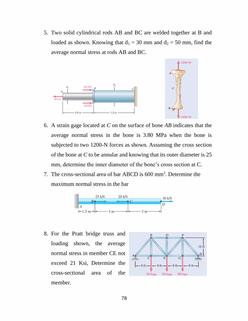
5. Two solid cylindrical rods AB and BC are welded together at B and
loaded as shown. Knowing that d1 = 30 mm and d2 = 50 mm, find the
average normal stress at rods AB and BC.
6. A strain gage located at C on the surface of bone AB indicates that the
average normal stress in the bone is 3.80 MPa when the bone is
subjected to two 1200-N forces as shown. Assuming the cross section
of the bone at C to be annular and knowing that its outer diameter is 25
mm, determine the inner diameter of the bone’s cross section at C.
7. The cross-sectional area of bar ABCD is 600 mm2. Determine the
maximum normal stress in the bar
8. For the Pratt bridge truss and
loading shown, the average
normal stress in member CE not
exceed 21 Ksi, Determine the
cross-sectional area of the
member.

79
9. Two steel plates are to be held together by means of 16 mm diameter
high-strength steel bolts fitting snugly inside cylindrical brass spacers.
Knowing that the average normal stress must not exceed 200 MPa in
the bolts and 130 MPa in the spacers, determine the outer diameter of
the spacers that yields the most economical and safe design.
10. The 1000-kg uniform bar AB is suspended from two cables AC and
BD; each with cross-sectional area 400 mm2. Find the magnitude P and
location x of the largest additional vertical force that can be applied to
the bar. The stresses in AC and BD are limited to 100 MPa and 50 MPa,
respectively.

80
Sheet (2)
1. What force is required to punch a 20
mm diameter hole in a plate that is 25
mm thick? The shear strength is 350
MN/m².
2. Compute the shearing stress in the pin
at B for the member supported as shown. The pin diameter is 20 mm.
3. A circular hole is to be punched o\in a plate having
a shearing strength of 275 MPa. The compressive
stress in the punch is limited to 345 MPa. (a)
Compute the maximum thickness of plate in
which a hole 64 mm diameter can be punched.
(b) If the plate is 6.5 mm thick, determine the
diameter of the smallest hole that can be
punched.
4. A load P is applied to a steel rod supported as shown by an aluminum
plate into which a 12-mm-diameter hole has been drilled. Knowing that

81
the shearing stress must not exceed 180 MPa
in the steel rod and 70 MPa in the aluminum
plate, determine the largest
load P that can be applied to the rod.
5. The yoke and rod connection are subjected to
a tensile force of 5 kN. Determine the average
normal stress in each rod and the average shear
stress in the pin at A.
6. An axial load P is supported by a short W250 x 67 column of cross-
sectional area A = 8580 mm2 and is distributed to a concrete foundation
by a square plate as shown. Knowing that the average normal stress in
the column must not exceed 150 MPa and that the bearing stress on the
concrete foundation must not exceed 12.5 MPa, determine the side a of
the plate that will provide the most economical and safe design.
7. Assume that the axial load P applied to the lap joint is distributed
equally among the three 20-mm-diameter
rivets. What is the maximum load P that can be
applied if the allowable stresses are 40 MPa for
shear in rivets, 90 MPa for bearing between a
plate and a rivet, and 120 MPa for tension in
the plates?

82
8.
9. Each of the four vertical links has an 8x36 mm uniform rectangular
cross section and each of the four pins has a 16-mm diameter.
Determine (a) the average shear stress at pin C (b) the average bearing
stress at pin C in link CE (c) the average bearing stress in member ABC
with uniform rectangular area 10x50 mm.

83
Sheet (3)
1. Link BC is 6 mm thick and is made of a steel with
a 450-MPa ultimate strength in tension. What
should be its width w if the structure shown is being
designed to support a 20-kN load P with a factor of
safety of 3?
2. Each of the two vertical links CF connecting the
two horizontal members AD and EG has a
10*40-mm uniform rectangular cross section and
is made of a steel with an ultimate strength in
tension of 400 MPa, while each of the pins at C
and F has a 20-mm diameter and are made of a
steel with an ultimate strength in shear of 150
MPa. Determine the overall factor of safety for
the links CF and the pins connecting them to the
horizontal members.
3. Link AB is to be made of a steel for which
the ultimate normal stress is 450 MPa.
Determine the cross-sectional area for AB
for which the factor of safety will be 3.5.
Assume that the link will be adequately
reinforced around the pins at A and B.

84
4. The steel bolts are to be used to attach the steel
plate shown to a wooden beam. Knowing that
the plate will support a load P = 110 KN, that
the ultimate shearing stress for the steel used
is 360 MPa, and that a factor of safety of 3.35
is desired, determine the required diameter of
the bolts.
5. Member ABC, which is supported by a pin
and bracket at C and a cable BD, was
designed to support the 16-kN load P as
shown. Knowing that the ultimate load for
cable BD is 100 kN, determine the factor of
safety with respect to cable failure.
6. Members AB and AC of the truss shown consist of
bars of square cross section made of the same
alloy. It is known that a 20-mm square bar of the
same alloy was tested for failure and that an
ultimate load of 120 kN was recorded. If bar AB
has a 15-mm square cross section, determine (a)
the factor of safety of bar AB, (b) the dimensions
of the cross section of bar AC if it is to have the
same factor of safety as bar AB.

85
7. Two wooden members shown, which support
20 KN load, are joined by plywood splices
fully glued on the surfaces in contact. The
ultimate shearing stress in the glue is 2.8 MPa
and the clearance between the members is 8
mm. Determine the required length L of each
splice if a factor of safety of 3.5 is to be
achieved.
8. Each of the steel links AB and CD is connected
to a support and to member BCE by 0.5-in.
diameter steel pins acting in single shear.
Knowing that the ultimate shearing stress is 30 ksi
for the steel used in the pins and that the ultimate
normal stress is 70 ksi for the steel used in the
links, determine the allowable load P if an overall
factor of safety of 3 is desired. (Note that the links
are not reinforced around the pin holes.
9. The hydraulic cylinder CF, which partially
controls the position of rod DE, has been locked
in the position shown. Member BD is 5/8 in. thick
and is connected to the vertical rod by a 3/8 -in.-
diameter bolt. Determine (a) the average shearing
stress in the bolt, (b) the bearing stress at C in
member BD.

86
Sheet (4)
1. An 80-m-long wire of 5-mm diameter is made of a steel with E = 200 GPa and an
ultimate tensile strength of 400 MPa. If a factor of safety of 3.2 is desired,
determine (a) the largest allowable tension in the wire, (b) the corresponding
elongation of the wire.
2. The aluminum rod ABC E = (10.1×10⁶ psi), which consists of
two cylindrical portions AB and BC, is to be replaced with a
cylindrical steel rod DE, E = (29×106 psi) of the same overall
length. Determine the minimum required diameter d of the steel
rod if its vertical deformation is not to exceed the deformation
of the aluminum rod under the same load and if the allowable
stress in the steel rod is not to exceed 24 ksi.
3. The specimen shown is made from a 1 in. diameter
cylindrical steel rod with two 1.5 in. outer-diameter
sleeves bonded to the rod as shown. Knowing that
E=29×106 psi, determine (a) the load P so that the total
deformation is 0.002 in., (b) the corresponding
deformation of the central portion BC.
4. Both portions of the rod ABC are made of an aluminum for which
E = 70 GPa. Knowing that the magnitude of P is 4 kN, determine
(a) the value of Q so that the deflection at A is zero, (b) the
corresponding deflection of B.

87
5. For the steel truss (E = 200 GPa) and loading
shown, determine the deformations of the
members AB and AD, knowing that their cross-
sectional areas are 2400 mm2 and 1800 mm2,
respectively.

88
Sheet (5)
1. For the 60-mm-diameter solid cylinder and
loading shown,
(a) Determine the maximum shearing stress.
(b) Determine the inner diameter of the
hollow cylinder, of 80-mm outer diameter, for
which the maximum stress is the same as in
part (a).
2. A circular steel shaft (G = 800
GPa) and aluminum shaft (G = 28
GPa) are attached and loaded as
shown, determine (a) the angle of
rotation of the section D with
respect to section A. (b) the
torsional shear stress at point E.
3. The torques shown are exerted on
pulleys A, B, and C. Knowing that
both shafts are solid, determine the
maximum shearing stress in (a) shaft
AB, (b) shaft BC.

89
4. Knowing that each of the shafts AB,
BC and CD consists of a solid circular
rod, determine (a) the shaft in which
the maximum shearing stress occurs,
(b) the magnitude of that stress.
5. A torque T = 3 kN.m is applied to the
solid bronze cylinder shown. Determine (a)
the maximum shearing stress, (b) the
shearing stress at point D, which lies on a
15-mm-radius circle drawn on the end of the
cylinder, (c) the percent of the torque
carried by the portion of the cylinder
within the 15-mm radius.
6. The steel shaft of a socket wrench has
a diameter of 8 mm. and a length of
200 mm. If the allowable stress in
shear is 60 MPa, what is the
maximum permissible torque Tmax
that may be exerted with the wrench?
Through what angle of twist in
degree will the shaft twist under the
action of the maximum torque? (Assume G = 78 GPa).

90
Sheet (6)
1. Knowing that the couple shown acts in a vertical
plane, determine the stress at (a) point A, (b) point
B.
2. A beam of the cross section shown is extruded from
an aluminum alloy for which σu = 450 MPa. Using a
factor of safety of 3.00, determine the largest couple
that can be applied to the beam when it is bent about
the z-axis.
3. Knowing that the couple shown acts in a vertical
plane, determine the stress at (a) point A, (b)
point B.
4. A nylon spacing bar has the cross section shown.
Knowing that the allowable stress for the grade of nylon
used is 24 MPa, determine the
largest couple Mz that can be applied to the bar.

91
5. Knowing that the couple shown acts in a vertical plane, determine the stress at
(a) point A, (b) point B.
6. Knowing that for the extruded beam shown the
allowable stress is 120 MPa in tension and 150 MPa
in compression, determine the largest couple M that
can be applied.