lectures notes of mechanics i
TRANSCRIPT

1
Modern University For Technology and Information
Department of Physics and Engineering Mathematics
Lectures Notes of Mechanics I
BENG 103
Prepared By Dr: Shaimaa Mostafa Dr: Mohamed H. Khobeiz
(First Edition 2021)

Vision
The vision of the Faculty of Engineering at MTI university is to be a center of excellence in engineering education and scientific research in
national and global regions. The Faculty of Engineering aims to prepare graduates meet the needs of society and contribute to sustainable development.
Mission The Faculty of Engineering MTI university aims to develop distinguished graduates that can enhance in the scientific and professional status, through the various programs which fulfill the needs of local and regional markets. The Faculty of Engineering hopes
to provide the graduates a highly academic level to keep up the global
developments.

COURSE OUTLINE
Chapter Title Page
1. Introduction 1
2. Equilibrium of particles 12
3. Rigid Body – Equivalent System of Forces 23
4. Equilibrium of Rigid Body 38
5. Trusses 50
6. Friction 63
7. Centroids and Centers of Gravity 72
8. Sheets 82
References
Vector Mechanics for Engineers, Beer & Johnston - Statics and Dynamics, Ninth Edition, 2009.
Engineering Mechanics, STATICS, R.C Hibbeler 13th Edition, (2012).
i
Chapter 1
Introduction
Contents:
Fundamental Concepts
Fundamental Principles
Systems of Units
Method of Problem Solution
Vectors
Addition of Vectors
Resultant of Two Forces
Resultant of Several Concurrent Force
1

1.1. What is Mechanics? • Mechanics is the science which describes and predicts the conditions of
rest or motion of bodies under the action of forces.
• Categories of Mechanics:
- Rigid bodies
Statics
Dynamics
- Deformable bodies
- Fluids
• Mechanics is an applied science - it is not an abstract or pure science
but does not have the empiricism found in other engineering sciences.
• Mechanics is the foundation of most engineering sciences and is a
necessary prerequisite to their study.
1.2. Fundamental Concepts • Space - associated with the notion (or imagine) of the position of a point
P given in terms of three coordinates measured from a reference point
or origin.
• Time - definition of an event, requires specification of the time and
position at which it occurred.
• Mass - used to characterize and compare bodies, e.g., response to
earth’s gravitational attraction and resistance to changes in translational
motion.
• Force - represents the action of one body on another. A force is
characterized by its point of application, magnitude, and direction, i.e.,
a force is a vector quantity.
2

• In Newtonian Mechanics, space, time, and mass are absolute concepts,
independent of each other. Force, however, is not independent of the
other three. The force acting on a body is related to the mass of the
body and the variation of its velocity with time.
1.3. Fundamental PrinciplesThe study of elementary mechanics rests on six fundamental principles:
1. The Parallelogram Law for the Addition of Forces. This states thattwo forces acting on a particle may be replaced by a single force,called their resultant , obtained by drawing the diagonal of the paral-lelogram which has sides equal to the given forces.
2. The Principle of Transmissibility. This states that the conditions ofequilibrium or of motion of a rigid body will remain unchanged if aforce acting at a given point of the rigid body is replaced by a force ofthe same magnitude and same direction, but acting at a different point,provided that the two forces have the same line of action.
Newton’s Three Fundamental Laws. Formulated by Sir Isaac Newton in the latter part of the seventeenth century, these laws can be stated as follows:
3. Newton’s First Law: If the resultant force on a particle is zero,
the particle will remain at rest or continue to move in a straight line.
4. Newton’s Second Law: A particle will have an
acceleration proportional to a nonzero resultant applied force.
F = ma 5. Newton’s Third Law:
The forces of action and reaction between two
particles have the same magnitude and line of
action with opposite sense.
3

6. Newton’s Law of Gravitation:
Newton states that two particles of masses M and m at a distance r from each other attract each other with equal and opposite forces F and -F directed along the line joining the particles. The common magnitude F of the two forces is
4

1.4. Systems of Units • Kinetic Units: length, time, mass, and force.
• Three of the kinetic units (length, time, mass), referred to as basic units,
may be defined arbitrarily. The fourth unit (force), referred to as a
derived unit, must have a definition compatible with Newton’s 2nd
Law,
F = ma
• International System of Units (SI):
The basic units are length, time, and mass which are arbitrarily
defined as the meter (m), second (s), and kilogram (kg). Force is the
derived unit,
• U.S. Customary Units:
The basic units are length, time, and force which are arbitrarily
defined as the foot (ft), second (s), and pound (lb). Mass is the
derived unit,
=aFm
1 slug = 1 lb
1 ft/s2
5

1.5. Method of Problem Solution - Problem Statement:
Includes given data, specification of what is to be determined, and a
figure showing all quantities involved.
- Free-Body Diagrams:
Create separate diagrams for each of the bodies involved with a clear
indication of all forces acting on each body.
- Fundamental Principles:
The six fundamental principles are applied to express the conditions of
rest or motion of each body. The rules of algebra are applied to solve the
equations for the unknown quantities.
Solution Check:
- Test for errors in reasoning by verifying that the units of the computed
results are correct,
- test for errors in computation by substituting given data and computed
results into previously unused equations based on the six principles,
- always apply experience and physical intuition to assess whether
results seem “reasonable”
6

1.6 Vectors
● Vector: parameters possessing magnitude anddirection which add according to theparallelogram law. Examples: displacements,velocities, accelerations.
● Scalar: parameters possessing magnitude butnot direction. Examples: mass, volume,temperature
● Equal vectors have the same magnitude anddirection.
● Negative vector of a given vector has thesamemagnitude and the opposite direction.
1.7 Addition of Vectors:
P
P
P
–P
A
PP + Q
Q
A
A
P
P
Q
Q
P + Q
P + Q
(a)
P –
Q
PP
Q
–Q
7

1.8 Resultant of Two Forces
●
●
Force: action of one body on another;characterized by its point= of =application=, =magnitude,= line of action=, and =sense.=Experimental evidence shows that the combined effect of two forces may be represented by a single resultant force.
● The resultant is equivalent to thediagonal of a parallelogram whichcontains the two forces in adjacent legs.
● Force is a vector quantity.
A
P
Q S
Q + S
P + Q + S
P
Q S
P + Q + S
A
P 1.5 P
–2 P
8

1.9 Resultant of Several Concurrent Forces: Concurrent forces: set of forces which all pass through the same point.
A set of concurrent forces applied to a particle may be replaced by a single resultant force which is the vector sum of the applied forces.
Vector force components: two or more force vectors which, together, have the same effect as a single force vector.
9

Example (1.1): The two forces act on a bolt at A. Determine their resultant. Solution:
Graphical solution : construct a parallelogram with sides in the same direction as P and Q and lengths in proportion. Graphically evaluate the resultant which is equivalent in direction and proportional in magnitude to the the diagonal.
10

Example (1.2) A barge is pulled by two tugboats. If the resultant of the forces exerted by the tugboats is 5000 lbf directed along the axis of the barge, determine: a) the tension in each of the ropes for α = 45o
b) the value of α for which the tension in rope 2 is a minimum.
Solution:
(a)the tension in each of the ropes
(b) the value of α:
11

Chapter 2
Equilibrium of particles
Contents
● Rectangular Components of a Force● Unit Vectors● Equilibrium of a Particle● Free-Body Diagrams● Rectangular Components in Space
12

2.1 Rectangular components of a Force When a force is resolved into two components along the x and y axes, the components are then called rectangular components . For analytical work we can represent these components in one of two ways, using either scalar notation or Cartesian vector notation.
Scalar Notation. The rectangular components of force F shown
in Fig. 1 are found using the parallelogram law, so that F = Fx + Fy . Because these components form a right triangle, they can be determined from
Fx = F cos u and Fy = F sin u
Instead of using the angle u, however, the direction of F can also be defined using a small “slope” triangle, as in the example shown in Fig. 1b. Since this triangle and the larger shaded triangle are similar, the proportional length of the sides gives
FxF
=ac
or
Fx = F a acb
and
Fy
F=bc
or
Fy = -Fa bcb
(a)
F
y
xFx
Fy
u
Fy
Fx
(b)
F
y
x
ab
c
Fig. 1
F3 � 200 N
(a)
y
�x
F1 � 400 N
F2 � 250 N
35
4
45�
Here the y component is a negative scalar since Fy is directed along the negative y axis.
It is important to keep in mind that this positive and negative scalar notation is to be used only for computational purposes, not for graphical representations in figures. Throughout the book , the head of a vector arrow in any figure indicates the sense of the vector graphically ; algebraic signs are not used for this purpose. Thus, the vectors in Figs. 1 a and 1b are designated by using boldface (vector) notation. * Whenever italic symbols are written near vector arrows in figures, they indicate the magnitude of the vector, which is always a positive quantity.
* Negative signs are used only in figures with boldface notation when showing equal butopposite pairs of vectors,
Example 2.1 The end of the boom O in Fig. 2a is subjected to three concurrent and coplanar forces. Determine the magnitude and direction of the resultant force
13

SOLUTION Each force is resolved into its x and y components, Fig. 2b . Summingthe x components, we have
+S (FR)x = �Fx; F( R)x = -400 N + 250 sin 45� N - 2001452 N
= -383.2 N = 383.2 N d
The negative sign indicates that FRx acts to the left, i.e., in the negative x direction, as noted by the small arrow. Obviously, this occurs because F1 and F3 in Fig. 2b contribute a greater pull to the left than F2which pulls to the right. Summing the y components yields
+ c (FR)y = �Fy; (FR)y = 250 cos 45� N + 200135 2 N
= 296.8 Nc
The resultant force, shown in Fig. 2 c , has a magnitude of
FR = 2(-383.2 N)2 + (296.8 N)2
Ans.= 485 N
From the vector addition in Fig. 2 c , the direction angle u is
u = tan-1a 296.8
383.2b = 37.8� Ans.
250 N
(b)
y
�
45�
400 N
4x
200 N
35
FR296.8 N
383.2 N
(c)
y
�x
u
Fig. 2
NOTE: Application of this method is more convenient, compared to using two applications of the parallelogram law, first to add F1 and F2 then adding F3 to this resultant.
2.2 Cartesian Vector Representation. Unit Vector
Since the three components of A act in the positive i , j, and k directions, Fig3 , we can write A in Cartesian vector form as
A = Axi + Ay j + Azk (2–3)
There is a distinct advantage to writing vectors in this manner. Separating the magnitude and direction of each component vector will simplify the operations of vector algebra, particularly in three dimensions.
Magnitude of a Cartesian Vector. It is always possible to obtain the magnitude of A provided it is expressed in Cartesian vector form. As shown in Fig. 4 , from the blue right triangle, A = 2A�2 + Az2 , and from the gray right triangle, A� = 2Ax
2 + Ay2 . Combining
these equations to eliminate A� yields
(2–4)
A
Ax i
z
y
x
Ay j
Az k
k
i
j
Fig. 3
A
Axi
z
y
x
Ayj
Azk
A
A¿
Ay
Ax
Az
Fig. 4
2 2A = 2Ax + Ay + Az2
14

Hence, the magnitude of A is equal to the positive square root of the sum of the squares of its components.
Direction of a Cartesian Vector. We will define the direction of A by the coordinate direction angles a (alpha), b (beta), and g (gamma), measured between the tail of A and the positive x, y, z axes provided they are located at the tail of A, Fig.5 . Note that regardless of where A is directed, each of these angles will be between 0° and 180°.
To determine a, b, and g, consider the projection of A onto the x, y, z axes, Fig. 6. Referring to the blue colored right triangles shown in each figure, we have
cos a =AxA cos b =
Ay
A cos g =
AzA (2–5)
These numbers are known as the direction cosines of A. Once they have been obtained, the coordinate direction angles a, b, g can then be determined from the inverse cosines.
A
Axi
z
y
x
Ayj
Azk
uA
g
a
b
Fig. 5
z
y
x
90�
A
Ax
a
z
y
x
90�
A
Ay
b
z
y
x
Az
90�
Ag
Fig. 6
An easy way of obtaining these direction cosines is to form a unit vector u A in the direction of A , Fig. 2–26 . If A is expressed in Cartesian vector form, A = Axi + Ay j + Azk , then u A will have a magnitude of one and be dimensionless provided A is divided by its magnitude, i.e.,
uA =AA
=AxAi +
Ay
A j +
AzA
k (2–6)
where A = 2Ax2 + Ay
2 + Az2 . By comparison with Eqs. 2–5 , it is seen that
the i , j , k components of u A represent the direction cosines of A , i.e.,
uA = cos a i + cos b j + cos g k (2–7)
15

Since the magnitude of a vector is equal to the positive square root of the sum of the squares of the magnitudes of its components, and u A has a magnitude of one, then from the above equation an important relation among the direction cosines can be formulated as
cos2 a + cos2 b + cos2 g = 1 (2–8)
Here we can see that if only two of the coordinate angles are known, the third angle can be found using this equation.
Finally, if the magnitude and coordinate direction angles of A are known, then A may be expressed in Cartesian vector form as
A = AuA(2–9)
= A cos a i + A cos b j + A cos g k = Axi + Ay j + Azk
2.3 Position Vector In this section we will introduce the concept of a position vector. It will be shown that this vector is of importance in formulating a Cartesian force vector directed between two points in space.
x , y , z Coordinates. Throughout the book we will use a right-handed coordinate system to reference the location of points in space. We will also use the convention followed in many technical books, which requires the positive z axis to be directed upward (the zenith direction) so that it measures the height of an object or the altitude of a point. The x, y axes then lie in the horizontal plane, Fig. 7 . Points in space are located
relative to the origin of coordinates, O, by successive measurements along the x, y, z axes. For example, the coordinates of point A are obtained by starting at O and measuring xA = +4 m along the x axis, then yA = +2 m along the y axis, and finally zA = - 6 m along the z axis. Thus, A (4 m, 2 m, - 6 m). In a similar manner, measurements along the x, y, z axes from O to B yield the coordinates of B, i.e., B (6 m, -1 m, 4 m).
Position Vector. A position vector r is defined as a fixed vector which locates a point in space relative to another point. For example, if r extends from the origin of coordinates, O, to point P ( x, y, z ), Fig. 8a , then r can be expressed in Cartesian vector form as
r = xi + yj + zk
Fig. 7
z
y
x
4 m
1 m
2 m
OB
A
2 m
4 m
6 m
16
z
y
x
y jr
x iO
z k
(a)
P(x, y, z)
Fig. 8
z
y
x
z kr
x iO
(b)
P(x, y, z)
y j

Example 2.2
The man shown in Fig. 9 a pulls on the cord with a force of 70 lb. Represent this force acting on the support A as a Cartesian vector and determine its direction.
SOLUTION Force F is shown in Fig. 9 b . The direction of this vector, u , is determined from the position vector r, which extends from A to B . Rather than using the coordinates of the end points of the cord, r can be determined directly by noting in Fig. 9 a that one must travel from A {-24k } ft, then {-8j } ft, and finally {12 i } ft to get to B . Thus,
r = 512i - 8j - 24k6 ft
The magnitude of r , which represents the length of cord AB , is
r = 2(12 ft)2 + (-8 ft)2 + (-24 ft)2 = 28 ft
Forming the unit vector that defines the direction and sense of both r and F , we have
r 12
28
8
28
24
28u =
r= i - j - k
Since F has a magnitude of 70 lb and a direction specified by u , then
F = Fu = 70 lba 12
28i -
8
28j -
24
28kb
= 530i - 20j - 60k6 lb Ans.
The coordinate direction angles are measured between r (or F ) and the positive axes of a localized coordinate system with origin placed at A , Fig. 9 b . From the components of the unit vector:
a = cos-1a 12
28b = 64.6� Ans.
b = cos-1a -8
28b = 107� Ans.
g = cos-1a -24
28b = 149� Ans.
y
x
z
A
30 ft
8 ft
6 ft
12 ft
B
(a)
Fig. 9
F � 70 lb
(b)
x¿
y¿
z¿
A
u
r
B
g
b
a
17

2.4 Equilibrium of a Particle
Condition for the Equilibrium
A particle is said to be in equilibrium if it remains at rest if originally at rest, or has a constant velocity if originally in motion. Most often, however, the term “equilibrium” or, more specifically, “static equilibrium” is used to describe an object at rest. To maintain equilibrium, it is necessary to satisfy Newton’s first law of motion, which requires the resultant force acting on a particle to be equal to zero. This condition may be stated mathematically as
�F = 0 (3–1)
where �F is the vector sum of all the forces acting on the particle. Not only is Eq. 3–1 a necessary condition for equilibrium, it is also a
sufficient condition. This follows from Newton’s second law of motion, which can be written as �F = ma. Since the force system satisfies Eq. 3–1 , then ma = 0, and therefore the particle’s acceleration a = 0.Consequently, the particle indeed moves with constant velocity or remains at rest.
The Free-Body Diagram To apply the equation of equilibrium, we must account for all the known and unknown forces ( �F) which act on the particle. The best way to do this is to think of the particle as isolated and “free” from its surroundings. A drawing that shows the particle with all the forces that act on it is called a free-body diagram (FBD).
Before presenting a formal procedure as to how to draw a free-body diagram, we will first consider two types of connections often encountered
in particle equilibrium problems.
Springs. If a linearly elastic spring (or cord) of undeformed length l0is used to support a particle, the length of the spring will change in direct proportion to the force F acting on it, Fig. 3–1 . A characteristic that defines the “elasticity” of a spring is the spring constant or stiffness k .
The magnitude of force exerted on a linearly elastic spring which has a stiffness k and is deformed (elongated or compressed) a distance s = l - l0, measured from its unloaded position, is
F = ks (3–2)
F
�s
l
l0
Fig. 3–1
18

T
u
Fig. 3–2
TCable is in tension
If s is positive, causing an elongation, then F must pull on the spring; whereas if s is negative, causing a shortening, then F must push on it. For example, if the spring in Fig. 3–1 has an unstretched length of 0.8 m and a stiffness k = 500 N>m and it is stretched to a length of 1 m, so that s = l - l0 = 1 m - 0.8 m = 0.2 m, then a force F = ks = 500 N>m(0.2 m) = 100 N is needed.
Cables and Pulleys. Unless otherwise stated throughout this book, except in Sec. 7.4, all cables (or cords) will be assumed to have negligible weight and they cannot stretch. Also, a cable can support only a tension or “pulling” force, and this force always acts in the direction of the cable. In Chapter 5 , it will be shown that the tension force developed in a continuous cable which passes over a frictionless pulley must have a constant magnitude to keep the cable in equilibrium. Hence, for any angle u, shown in Fig. 3–2 , the cable is subjected to a constant tension T throughout its length.
2.5 Three-Dimensional Force Systems
In Section 3.1 we stated that the necessary and sufficient condition for particle equilibrium is
�F = 0 (3–4)
In the case of a three-dimensional force system, as in Fig. 3–9 , we can resolve the forces into their respective i , j , k components, so that �Fxi + �Fy j + �Fzk = 0 . To satisfy this equation we require
�Fx = 0
�Fy = 0
�Fy = 0(3–5)
These three equations state that the algebraic sum of the components of all the forces acting on the particle along each of the coordinate axes must be zero. Using them we can solve for at most three unknowns, generally represented as coordinate direction angles or magnitudes of forces shown on the particle’s free-body diagram.
F3F2
F1
x
y
z
Fig. 3–9
19

Example 2.3 A 90-lb load is suspended from the hook shown in Fig. 3–10 a . If the load is supported by two cables and a spring having a stiffness k = 500 lb>ft, determine the force in the cables and the stretch of the spring for equilibrium. Cable AD lies in the x–y plane and cable AC lies in the x–z plane.
SOLUTION The stretch of the spring can be determined once the force in the spring is determined.
Free-Body Diagram. The connection at A is chosen for the equilibrium analysis since the cable forces are concurrent at this point. The free-body diagram is shown in Fig. 3–10 b .
Equations of Equilibrium. By inspection, each force can easily be resolved into its x, y, z components, and therefore the three scalar equations of equilibrium can be used. Considering components directed along each positive axis as “positive,” we have
FD sin 30� - 1452FC = 0 (1)
(2)
�Fx = 0;
�Fy = 0;
�Fz = 0;
-FD cos 30� + FB = 0
135 2FC - 90 lb = 0 (3)
Solving Eq. ( 3 ) for FC, then Eq. ( 1) for FD, and finally Eq. (2 ) for FB, yields
Ans.
Ans.
FC = 150 lb
FD = 240 lb
FB = 207.8 lb = 208 lb Ans.
The stretch of the spring is therefore
FB = ksAB
207.8 lb = (500 lb>ft)(sAB)
sAB = 0.416 ft Ans.
NOTE: Since the results for all the cable forces are positive, each cable is in tension; that is, it pulls on point A as expected, Fig. 3–10 b .
y
x
z
(b)
30�
90 lb
A
5 3
4
FC
FB
FD
x
y
z
(a)
30�
C
90 lb
A
354k = 500 lb/ft
B
D
Fig. 3–10
20

Example 2.4 Determine the force in each cable used to support the 40-lb crate shown in Fig. 3–12 a .
SOLUTION Free-Body Diagram. As shown in Fig. 3–12 b , the free-body diagram of point A is considered in order to “expose” the three unknown forces in the cables.
Equations of Equilibrium. First we will express each force in Cartesian vector form. Since the coordinates of points B and C
are B(-3 ft, -4 ft, 8 ft) and C ( -3 ft, 4 ft, 8 ft), we have
-3i - 4j + 8kFB = FB J
2 2 2R
2(-3) + (-4) + (8)
= -0.318FBi - 0.424FBj + 0.848FBk
-3i + 4j + 8kFC = FC J R
2(-3)2 + (4)2 + (8)2
= -0.318FCi + 0.424FC j + 0.848FCk
FD = FDi
W = 5-40k6 lb
Equilibrium requires
�F = 0; FB + FC + FD + W = 0
-0.318FBi - 0.424FB j + 0.848FBk
-0.318FCi + 0.424FC j + 0.848FCk + FDi - 40k = 0
Equating the respective i , j , k components to zero yields
(1) -0.318FB - 0.318FC + FD = 0
-0.424FB + 0.424FC = 0 (2)
0.848FB + 0.848FC - 40 = 0 (3)
Equation (2) states that FB = FC. Thus, solving Eq. (3 ) for FB and FC
and substituting the result into Eq. (1 ) to obtain FD, we have
Ans.FB = FC = 23.6 lb
FD = 15.0 lb Ans.
y
x
z
(a)
8 ft
3 ft
4 ft
4 ft
C
B
D A
Fig. 3–12
y
x
z
W � 40 lb
(b)
FB
FC
�Fx = 0;
�Fy = 0;
�Fz = 0;
21

Example 2.5 Determine the tension in each cord used to support the 100-kg crate shown in Fig. 3–13 a .
SOLUTION Free-Body Diagram. The force in each of the cords can be determined by investigating the equilibrium of point A. The free-body diagram is shown in Fig. 3–13 b . The weight of the crate is W = 100(9.81) = 981 N.
Equations of Equilibrium. Each force on the free-body diagram is first expressed in Cartesian vector form. Using Eq. 2–9 for FC and noting point D(–1 m, 2 m, 2 m) for FD, we have
FB = FB i
FC = FC cos 120�i + FC cos 135�j + FC cos 60�k
= -0.5FCi - 0.707FCj + 0.5FCk
FD = FD J -1i + 2j + 2k
2(-1)2 + (2)2 + (2)2R
= -0.333FDi + 0.667FDj + 0.667FDk
W = 5-981k6 N
Equilibrium requires
�F = 0; FB + FC + FD + W = 0
FBi - 0.5FCi - 0.707FC j + 0.5FCk
-0.333FD i + 0.667FD j + 0.667FDk - 981k = 0
�
Equating the respective i , j , k components to zero,
Fx = 0; FB - 0.5FC - 0.333FD = 0 (1)
(2) �Fy = 0;
�Fz = 0;
-0.707FC + 0.667FD = 0
0.5FC + 0.667FD - 981 = 0 (3)
Solving Eq. ( 2 ) for FD in terms of FC and substituting this into Eq. ( 3 ) yields FC. FD is then determined from Eq. (2 ). Finally, substituting the results into Eq. ( 1 ) gives FB. Hence,
FC = 813 N Ans.
FD = 862 N Ans.
FB = 694 N Ans.
1 m y
2 m
z
60� 135�2 m
D
120�
x
(a)
B
A
k � 1.5 kN/m
C
Fig. 3–13
y
x
z
W � 981 N
A
FC
(b)
FD
FB
22
Chapter 3
Rigid Bodies: Equivalent Systems of Forces
Contents:
3.1 Introduction
3.2 External and Internal Forces
3.3 Moment of a Force About a Point (Scalar Formulation)
3.4 Vector Products of Two Vectors
3.5 Vector Products: Rectangular Components
3.6 Moment of a Force About a Point (Vector Formulation)
3.7 Varignon’s Theorem
3.8 Rectangular Components of the Moment of a Force
3.9 Moment of a Force About a Given Axis
3.10 Moment of a Couple
23
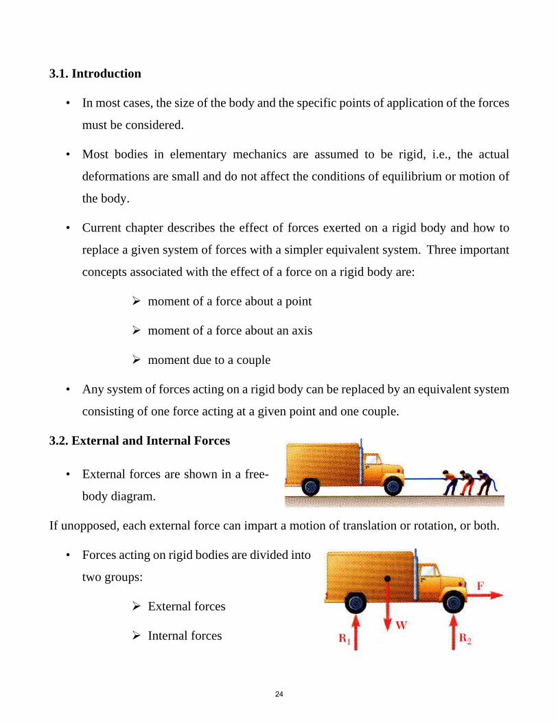
3.1. Introduction
• In most cases, the size of the body and the specific points of application of the forces
must be considered.
• Most bodies in elementary mechanics are assumed to be rigid, i.e., the actual
deformations are small and do not affect the conditions of equilibrium or motion of
the body.
• Current chapter describes the effect of forces exerted on a rigid body and how to
replace a given system of forces with a simpler equivalent system. Three important
concepts associated with the effect of a force on a rigid body are:
moment of a force about a point
moment of a force about an axis
moment due to a couple
• Any system of forces acting on a rigid body can be replaced by an equivalent system
consisting of one force acting at a given point and one couple.
3.2. External and Internal Forces
• External forces are shown in a free-
body diagram.
If unopposed, each external force can impart a motion of translation or rotation, or both.
• Forces acting on rigid bodies are divided into
two groups:
External forces
Internal forces
24

2 m
O
(b)
50 N
0.75 m
2 ft
(c)
O
4 ft2 cos 30� ft
40 lb30�
(d)
O1 sin 45� ft
60 lb
3 ft
45�1 ft
2 m
O (e)
4 m
1 m7 kN
2 m
O
(a)
3.3. Moment of a force about a point (scalar formulation)
Example (3.1)
For each case illustrated in the figure, determine the moment of the force about point O.
100N
Solution Fig. a: Mo = (100 N) (2 m) = 200 N.m Fig. b: Mo = (50 N) (0.75 m) = 37.5 N.m Fig. c: Mo = (40 lb) (4 ft + 2 cos 30o ft) = 229 lb.ft Fig. d: Mo = (60 lb) (1 sin 45o ft) = 42.4 lb.ft Fig. e: Mo = (7 KN) (4 m - 1 m) = 21 KN.m
25

Example (3.2)
A 100-lb vertical force is applied to the end of a lever which is attached to a shaft at O, Determine:
a) moment about O,
b) horizontal force at A which creates the same moment,
c) smallest force at A which produces the same moment,
d) location for a 240-lb vertical force to produce the samemoment
Solution
a) Moment about O
FdFd((2424inin..))101000 lblb))(((( 1212 inin..))
cocoss6060°° ==1212 inin..======
OO
OO
MMdd
MM
MMOO ==12001200 lblb ⋅⋅ iinn
26
b) horizontal force at A which creates the same moment
FdFd(( ))
((FF ))
2020..88 inin.. inin..12001200 lblb
2020..88 inin.. 12001200 lblb
2424 inin.. sisinn 6060°° == 2020..88 inin..
⋅⋅==
⋅⋅ inin.. ======
FF
MMdd
OO
FF == 5757..77 lblb

c) The smallest force A to produce the same moment
occurs when the perpendicular distance is a maximum
or when F is perpendicular to OA
( )
in. 42in. lb 1200
in. 42in. lb 1200⋅
=
=⋅=
F
FFdMO( )
in. 42in. lb 1200
in. 42in. lb 1200⋅
=
=⋅=
F
FFdMO
lb 50=F lb 50=F
d) To determine the point of application of a 240 lb force
to produce the same moment,MMOO FdFd
(( ))
coscos6060°° == 55 inin..
55 inin..224040 lblb
inin..12001200 lblb 240240 lblb12001200 lblb
==⋅⋅
==
⋅⋅ inin.. ====
OBOB
dd
dd
OBOB ==1010 inin..
27

Resultant Moment
For two-dimensional problems, where all the forces lie within the x–y plane, the resultant moment (MR)o about point O (the z axis) can be determined by finding the algebraic sum of the moments caused by all the forces in the system. As a convention, we will generally consider positive moments as counterclockwise since they are directed along the positive z axis (out of the page). Clockwise moments will be negative.
Example (3.3)
Determine the resultant moment of the four forces acting on
the shown rod about point 0.
Solution
Mo = Σ F.d
Mo = -50 N (2 m) + 60 N (0) + 20 N (3 sin 30 m)
- 40 N (4 m + 3 cos 30o m)
Mo = 334 N.m
50 N
40 N
20 N3 m
2 m 2 m
O
x
y
60 N
30�

3.4. Vector Product of Two Vectors
• Vector product of two vectors P and Q is defined as the vector V which satisfies the
following conditions:
1. Line of action of V is perpendicular to plane containing P and Q.
2. Magnitude of V is
3. Direction of V is obtained from the right-hand
rule.
3.5. Vector Products - Rectangular Components
Vector products of Cartesian unit Vectors
Vector products in terms of rectangular coordinates
VV ))== ((PPxxii++ PPyy
jj ++ PPzzkk
))×× ((QQxxii++QQyy
jj ++QQzzkk
PP QQ ))kk((PP QQ
PP QQzz −− PPzzQQyy ))ii++ ((PP −− PP )) jj== ((
yy xxxx yy
xxQQzzzzQQxxyy
−−++
zzyyxx
zzyyxxQQQQQQPPPPPPkkjjii
==
28

3.6. Moment of a Force About a Point - Vector formulation
• A force vector is defined by its magnitude and direction.
Its effect on the rigid body also depends on its point
of application.
• The moment of F about O is defined as
FrMO ×= FrMO ×=
• The moment vector MO is perpendicular to the plane
containing O and the force F.
• Magnitude of MO measures the tendency of the force to cause rotation of the body
about an axis along MO.
MMOO == rFrF sinsinθθ == FdFd
• The sense of the moment may be determined by the right-hand rule.• The plane of the structure contains the point O and the force F.• MO, the moment of the force about O is perpendicular to the plane.
29

Solution
x
y
z
O A
B
rA
rB
F1
F2
x
y
z
O
� 39.8�
� 67.4�
� 121�
(MR)O
� {30i � 40j � 60k} lb·ft
(c)
a
gb
rA = {5j} ft
rB = {4i + 5j - 2k} ft
The resultant moment about O is therefore
(MR)O
= �(r * F)
= rA * F1 + rB * F2
i j k0 5 0
-60 40 20
i j k4 5
80 40 -30
= 3 3 + 3 -2 3= [5(20) - 0(40)]i - [0]j + [0(40) - (5)(-60)]k
+ [5(-30) - (-2)(40)]i - [4(-30) - (-2)(80)]j + [4(40) - 5(80)]k
= {30i - 40j + 60k} lb # ft
30
Example (3.4)
Two forces act on the shown rod. Determine the resultant moment they create about the flange at O. Express the result as a Cartesian vector.
x
z
O
5 ft
4 ft
2 ft
A
B
F2 � {80i � 40j � 30k} lb
F1 � {�60i � 40j � 20k} lb
y

3.7. Varignon’s Theorem
• The moment about a given point O of
the resultant of several concurrent forces is
equal to the sum of the moments of the
various moments about the same point O.
( )
+×+×=++× 2121 FrFrFFr ( )
+×+×=++× 2121 FrFrFFr
3.8. Rectangular Components of the Moment of a Force
• The moment of F about O,
kFjFiFFkzjyixr
FrM
zyx
O
++=++=
×= ,
kFjFiFFkzjyixr
FrM
zyx
O
++=++=
×= ,
( ) ( ) ( )kyFxFjxFzFizFyF
FFFzyxkji
kMjMiMM
xyzxyz
zyx
zyxO
−+−+−=
=
++=
( ) ( ) ( )kyFxFjxFzFizFyF
FFFzyxkji
kMjMiMM
xyzxyz
zyx
zyxO
−+−+−=
=
++=
31

Example (3.5)
The rectangular plate is supported by the brackets at A and
B and by a wire CD. Knowing that the tension in the wire
is 200 N, determine the moment about A of the force
exerted by the wire at C.
Solution
The moment M A about A of the force F exerted by the wire on point C is obtained by forming the vector product
(1) MA 5 rC/A 3 F
where r C/A is the vector drawn from A to C ,
rC/A 5 AC¡
5 (0.3 m)i 1 (0.08 m)k (2)
and F is the 200-N force directed along CD . Introducing the unit vectorL 5 CD
¡/CD, we write
F 5 FL 5 (200 N) CD¡
CD (3)
¡ Resolving the vector CD into rectangular components, we have
CD¡
5 2(0.3 m)i 1 (0.24 m)j 2 (0.32 m)k CD 5 0 .50 m
Substituting into (3), we obtain
F 5200 N
[2(0.3 m)i 1 (0.24 m)j 2 (0.32 m)k]0.50 m
5 2(120 N)i 1 (96 N)j 2 (128 N)k (4)
Substituting for r C/A and F from (2) and (4) into (1), we obtain
MA 5 rC/A 3 F
MA 5 †i j k
xC 2 xA yC 2 yA zC 2 zA
Fx Fy Fz
† 5 †i j k
0.3 0 0.082120 96 2128
†
MA 5 2(7.68 N ? m)i 1 (28.8 N ? m)j 1 (28.8 N ? m)k ◀
rC/A
A
B
C
D
x
y
z
O0.08 m
0.08 m 0.3 m
200 N0.24 m
0.24 m
A
C
D
(28.8 N•m) j
(28.8 N•m) k
– (7.68 N•m) i
F = (200 N)�
32

3.9. Moment of a Force About a Given Axis
• Moments of F about the coordinate axes,
xyz
zxy
yzx
yFxFMxFzFMzFyFM
−=
−=
−=
xyz
zxy
yzx
yFxFMxFzFMzFyFM
−=
−=
−=
Example (3.6)
Determine the resultant moment of the three forces
shown in the figure about the x axis, y axis and z axis.
Solution
A force that is parallel to a coordinate axis or has a line
of action that passes through the axis does not produce
any moment about that axis. Therefore, the resultant
moment become:
2 ft
2 ft2 ft 3 ft
xy
z
B
C
A
O
F3 � 40 lb
F2 � 50 lb
F1 � 60 lb
Mx = (60 lb) (2 ft) + (50 lb) (2 ft) + 0 = 220 lb # ft Ans.
My = 0 - (50 lb)(3 ft) - (40 lb)(2 ft) = -230 lb # ft Ans.
Mz = 0 + 0 - (40 lb)(2 ft) = -80 lb # ft Ans.
jj ++ MM zzkkMM ii ++ MMMM yyxxOO
==
y
x
z
r
L
A
C
O
MOF
�� which shows that the moment M OL of F about the axis OL is the scalar obtained by forming the mixed triple product of L, r, and F. Expressing M OL in the form of a determinant.
MOL 5 L ? MO 5 L ? (r 3 F)
33

Example (3.7)
A cube is acted on by a force P as shown. Determine the
moment of P
a) about A
b) about the edge AB and
c) about the diagonal AG of the cube.
d) Determine the perpendicular distance between
AG and FC.
Solution • Moment of P about A
( )
( jiaM
P
jiajaiar
PrM
A
AF
AFA
×−=
=
−=−=
×=
2
( )
( jiaM
P
jiajaiar
PrM
A
AF
AFA
×−=
=
−=−=
×=
2
)( )kjiM A
++= 2)( )kji((aaPP/M A
++= 2
• Moment of P about AB,
)( )kjii
MiM AAB
++•=
•=
2)( )kji((aPaP/i
MiM AAB
++•=
•=
2
PP−−jjkk(( ))
))22
PP−−jjkk(( ))
))((
34

22MM AABB == aPaP/
• Moment of P about the diagonal AG,
( )
( )
( ) ( )
( )1116
2312
31
3
−−=
++•−−=
++=
−−=−−
==
•=
aP
kjiaPkjiM
kjiaPM
kjia
kajaiarr
MM
AG
A
GA
GA
AAG
λ
λ
( )
( )
( ) ( )
( )1116
2312
31
3
−−=
++•−−=
++=
−−=−−
==
•=
aP
kjiaPkjiM
kjiaPM
kjia
kajaiarr
MM
AG
A
GA
GA
AAG
λ
λ
6aPM AG −=
6aPM AG −=
• Perpendicular distance between AG and FC,
( ) ( ) ( )
0
11063
12
=
+−=−−•−=•PkjikjPP
λ ( ) ( ) ( )
0
11063
12
=
+−=−−•−=•PkjikjPP
λ
• Therefore, P is perpendicular to AG.
PdaPM AG ==6
PdaPM AG ==6
66dd ==
aa
35

3.10. Moment of a Couple
• Two forces F and -F having the same magnitude, parallel
lines of action, and opposite sense are said to form a couple.
• Moment of the couple,
( )( )
FdrFMFr
FrrFrFrM
BA
BA
==×=
×−=
−×+×=
θsin
( )( )
FdrFMFr
FrrFrFrM
BA
BA
==×=
×−=
−×+×=
θsin
• The moment vector of the couple is independent of
the choice of the origin of the coordinate axes, i.e., it
is a free vector that can be applied at any point with
the same effect.
• If more than two couple moments act on the body. we
can write the vector resultant as:
MR = Σ (r × F)
Example (3.8)
Determine the resultant couple moment of the three couples acting on the plate shown in the figure.
Solution
As shown, the perpendicular distances between each pair of couple forces are:
d1 = 4 ft, d2 = 3 ft and d3 = 5 ft,
MR = Σ M = Σ (r × F) = Σ (F × d)
MR = -F1.d1 + F2.d2 - F3.d3
= -(200 × 4) + (450 × 3) -(300 × 5) = - 950 lb.ft
F2 � 450 lb
F1 � 200 lbF3 � 300 lb
F3 � 300 lb
F2 � 450 lb
d3 � 5 ft
F1 � 200 lb
A
B
d2 � 3 ft
d1 � 4 ft
36

Example (3.9)
Determine the components of the single couple equivalent to the
couples shown.
Solution
• Attach equal and opposite 20 lb forces in the +x direction at A
( )( )( )( )( )( ) in.lb 180in. 9lb 20
in.lb240in. 12lb 20in.lb 540in. 18lb 30
⋅+=+=
⋅+=+=⋅−=−=
z
y
x
MMM ( )( )
( )( )( )( ) in.lb 180in. 9lb 20
in.lb240in. 12lb 20in.lb 540in. 18lb 30
⋅+=+=
⋅+=+=⋅−=−=
z
y
x
MMM
( ) ( )( )k
jiM
in.lb 180in.lb240in.lb 540
⋅+
⋅+⋅−= ( ) ( )( )k
jiM
in.lb 180in.lb240in.lb 540
⋅+
⋅+⋅−=
• Alternatively, compute the sum of the moments of the
four forces about D
( ) ( )( ) ( )[ ] ( )ikj
kjMM D
lb 20in. 12in. 9
lb 30in. 18
−×−+
−×== ( ) ( )( ) ( )[ ] ( )ikj
kjMM D
lb 20in. 12in. 9
lb 30in. 18
−×−+
−×==
( ) ( )( )k
jiM
in.lb 180in.lb240in.lb 540
⋅+
⋅+⋅−= ( ) ( )( )k
jiM
in.lb 180in.lb240in.lb 540
⋅+
⋅+⋅−=
37

Chapter 4
Equilibrium of a Rigid Body
Contents:
Introduction
Free-Body Diagram
Reactions at Supports and Connections for a Two-Dimensional Structure
Equilibrium of a Rigid Body in Two Dimensions
Sample Problem 4.1
Sample Problem 4.2
Sample Problem 4.3
Equilibrium of a Rigid Body in Three Dimensions
Reactions at Supports and Connections for a Three-Dimensional Structure
Sample Problem 4.4
Sample Problem 4.5
38

4.1. Introduction
For a rigid body in static equilibrium, the external forces and moments are
balanced. The necessary and sufficient condition for the static equilibrium of
a body are that the resultant force and couple from all external forces form a
system equivalent to zero,
Resolving each force and moment into its rectangular components leads to 6
scalar equations which also express the conditions for static equilibrium,
4.2. Free-Body Diagram
First step in the static equilibrium analysis of a
rigid body is identification of all forces acting on
the body with a free-body diagram.
• Select the extent of the free-body and detach it
from the ground and all other bodies.
• Indicate point of application, magnitude, and
direction of external forces, including the rigid
body weight.
• Indicate point of application and assumed
direction of unknown applied forces. These
usually consist of reactions through which the ground and other bodies oppose
the possible motion of the rigid body.
• Include the dimensions necessary to compute the moments of the forces.
39

4.3. Reactions at Supports and Connections for a Two Dimensional
Structure
Table 1: Supports for rigid bodies subjected to two-dimensional force system
(3)
Types of Connection Reaction Number of Unknowns
One unknown. The reaction is a tension force which actsaway from the member in the direction of the cable.
One unknown. The reaction is a force which acts alongthe axis of the link.
One unknown. The reaction is a force which actsperpendicular to the surface at the point of contact.
One unknown. The reaction is a force which actsperpendicular to the slot.
One unknown. The reaction is a force which actsperpendicular to the surface at the point of contact.
One unknown. The reaction is a force which actsperpendicular to the surface at the point of contact.
One unknown. The reaction is a force which actsperpendicular to the rod.
continued
(1)
cable
F
(2)
weightless linkF
roller F
u or
(6)
roller or pin inconfined smooth slot
(4)
rocker
(5)
smooth contacting surface
F
F
F
(7)
or
orF
F
F
member pin connectedto collar on smooth rod
u
uu
uu
u u
u
u
u
u
uu u
u
u
40

Types of Connection Reaction Number of Unknowns
Two unknowns. The reactions are two components offorce, or the magnitude and direction of the resultantforce. u Note that and are not necessarily equal [usuallynot, unless the rod shown is a link as in (2)].
Three unknowns. The reactions are the couple moment and the two force components, or the couple moment and the magnitude and direction of the resultant forcef .
Two unknowns. The reactions are the couple moment and the force which acts perpendicular to the rod.
F
Fy
M
or
Fx
F
fixed support
Fy
Fx
F
or
M M
f
f
TABLE 1 Continued
member fixed connected to collar on smooth rod
smooth pin or hinge
(8)
(9)
(10)
u f
f
41

4.4. Equilibrium of a Rigid Body in Two Dimensions
Any couple moments acting on the body are directed perpendicular to this
plane. This type of force and couple system is often referred to as a two-
dimension (2D) force system. For example, the airplane in the figure has a
plane of symmetry through its center axis.
and so the loads acting on the airplane are
symmetrical with respect to this plane.
Thus, each of the two wing tires will
support the same load T, which is
represented on the side (two-dimensional)
view of the plane as 2T.
Equations of equilibrium become:
= 0 = 0 = 0Ayx MFF
where A is any point in the plane of the structure.
The 3 equations can be solved for no more than 3
unknowns.
The 3 equations cannot be augmented with additional
equations, but they can be replaced
= 0 0 = = 0BAx MMF
C
A B
D
QP S
(a)
C
A B
D
(b)
Py Qy Qx
SySx
W
Px
B
Ax
Ay

Example (4.1):
A fixed crane has a mass of 1000 kg and is used
to lift a 2400 kg crate. It is held in place by a pin
at A and a rocker at B. The center of gravity of
the crane is located at G. Determine the
components of the reactions at A and B.
Solution:
• Create a free-body diagram for the crane.
• Determine B by solving the equation for the
sum of the moments of all forces about A.
42
( ) ( )
23.5 kN(6m) 0
1.5m −9.81kN 2m0 :
=−
M = + BA
B = +107.1kN
• Determine the reactions at A by solving the equations for the sum of all
horizontal force components and all vertical force components.
F = 0: A + B = 0x x xA
−9.81kN−23.5kN = 0= 0: y y AF
= −107.1kN
= +33.3 kNyA
• Check the values obtained for the reactions by verifying that the sum of
the moments about B of all forces is zero.

Example (4.2):
A loading car is at rest on an inclined track. The gross
weight of the car and its load is 5500 lb, and it is
applied at at G. The car is held in position by
the cable. Determine the tension in the cable and the
reaction at each pair of wheels.
Solution:
Create a free-body diagram
( )
( )
lb 2320
25sinlb 5500
lb 4980
25coslb 5500
−=
−=
+=
+=
o
o
y
x
W
W
43
Determine the reactions at the wheels
Determine the cable tension.
( ) (
(50in.) = 0
4980 lb)6in.2320 lb 25in.0 :
2+
−−=
R
M A
R2 =1758 lb
( ) (
(50in.) = 0
4980 lb)6in.2320 lb 25in.0 :
1−
−+=
R
M B
R1 = 562 lb
Fx = 0 : + 4980 lb−T = 0
T = +4980 lb

Example (4.3):
The frame supports part of the
roof of a small building. The
tension in the cable is 150 kN.
Determine the reaction at the
fixed end E.
Solution:
• Create a free-body diagram for
the frame and cable.
• Solve 3 equilibrium equations
for the reaction force
components and couple at E.
44
(150kN)= 07.5
4.5= 0 : +x x EF = −90.0 kNxE
(150kN) = 07.5
6Fy = 0 : Ey − 4(20kN)−
Ey = +200 kN
M E = 0 : ( ) ( )
( ) ( )
0(150kN )4.5m6
20kN 1.8m20kN 3.6m
20kN 5.4m20kN 7.2m
=+−
++
++
M E
mkN.0180 =E7.5
M
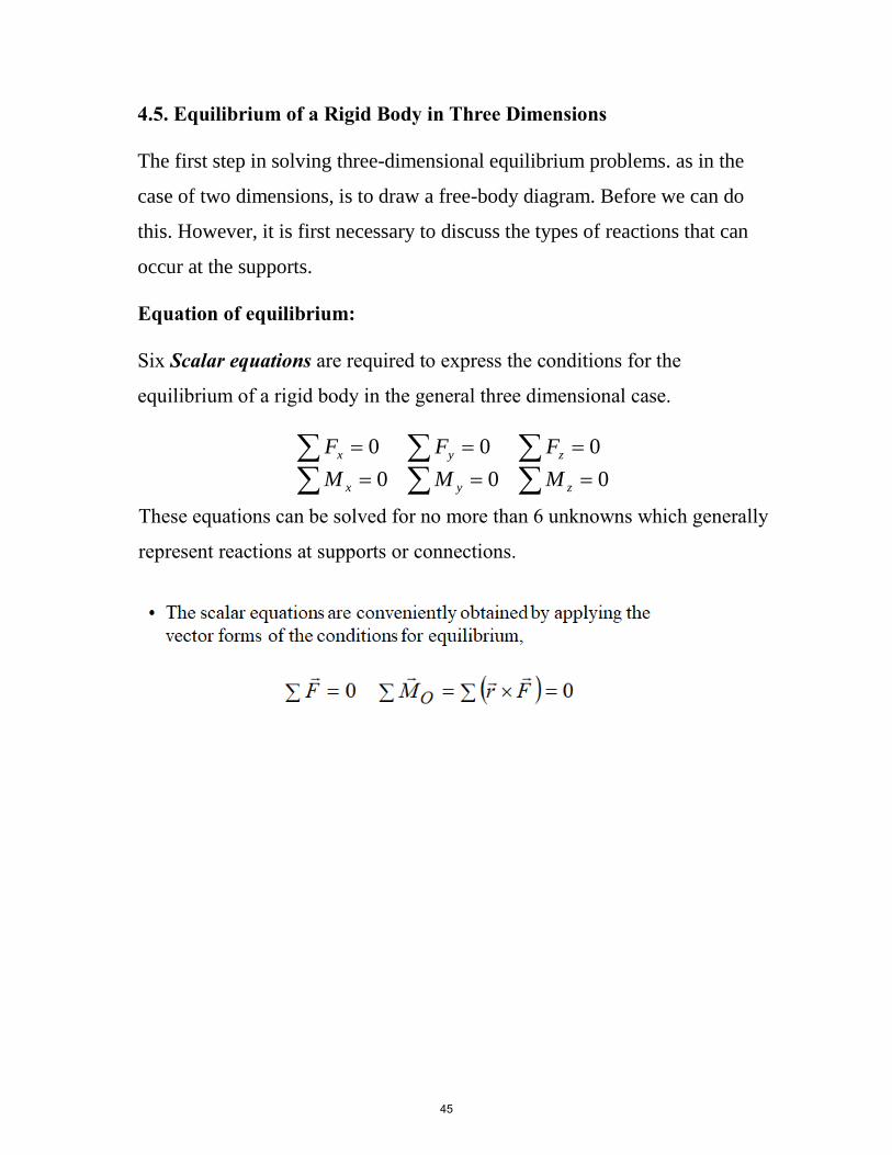
4.5. Equilibrium of a Rigid Body in Three Dimensions
The first step in solving three-dimensional equilibrium problems. as in the
case of two dimensions, is to draw a free-body diagram. Before we can do
this. However, it is first necessary to discuss the types of reactions that can
occur at the supports.
Equation of equilibrium:
Six Scalar equations are required to express the conditions for the
equilibrium of a rigid body in the general three dimensional case.
===
===
000
000
zyx
zyx
MMM
FFF
These equations can be solved for no more than 6 unknowns which generally
represent reactions at supports or connections.
45

Types of Connection Reaction Number of Unknowns
continued
One unknown. The reaction is a force which acts away from the member in the known direction of the cable.
One unknown. The reaction is a force which acts perpendicular to the surface at the point of contact.
One unknown. The reaction is a force which acts perpendicular to the surface at the point of contact.
Three unknowns. The reactions are three rectangular force components.
Four unknowns. The reactions are two force and two couple-moment components which act perpendicular to the shaft. Note: The couple moments are generally not applied if the body is supported elsewhere. See the examples.
F
F
F
Fz
FyFx
single journal bearing
Fz
Fx
Mz
Mx
(1)
cable
(2)
(3)
roller
ball and socket
(4)
(5)
smooth surface support
TABLE 2 Supports for Rigid Bodies Subjected to Three-Dimensional Force Systems
46
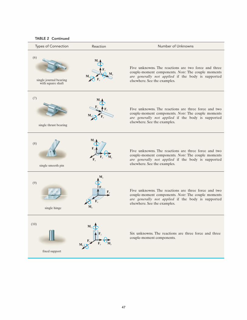
Reaction Number of Unknowns
Five unknowns. The reactions are two force and three couple-moment components. Note: The couple moments are generally not applied if the body is supported elsewhere. See the examples.
Five unknowns. The reactions are three force and two couple-moment components. Note: The couple moments are generally not applied if the body is supported elsewhere. See the examples.
Five unknowns. The reactions are three force and two couple-moment components. Note: The couple moments are generally not applied if the body is supported elsewhere. See the examples.
Five unknowns. The reactions are three force and two couple-moment components. Note: The couple moments are generally not applied if the body is supported elsewhere. See the examples.
Six unknowns. The reactions are three force and three couple-moment components.
Fz
Fx
Mz
Mx
Fy
Fz
Fx
Mz
MxMy
Fz
Mz
Fx
Fy My
Mz
Fx
Fy
Mx
Fz
Mz
FxMyMx
Fy
Fz
Types of Connection
TABLE 2 Continued
single hinge
fixed support
single thrust bearing
single journal bearingwith square shaft
single smooth pin
(7)
(6)
(8)
(10)
(9)
47

x
y
z
A
B
CD
0.4 m
0.4 m
(a)
0.6 m
900 N
0.4 m0.4 m
A
x
y
z
0.4 m
0.4 m
(b)
0.6 m0.4 m
0.4 mFC
Bz
Az Bx
Ax
Ay
900 N
SOLUTION Free-Body Diagram. As shown on the free-body diagram, the reactive forces of the supports will prevent the assembly from rotating about each coordinate axis, and so the journal bearing at B only exerts reactive forces on the member. No couple moments are required.
Equations of Equilibrium. A direct solution for Ay can be obtained by summing forces along the y axis.
�Fy = 0; A y = 0 Ans .
The force FC can be determined directly by summing moments about the y axis.
�My = 0; FC(0.6 m) - 900 N(0.4 m) = 0
FC = 600 N Ans .
Using this result, Bz can be determined by summing moments about the x axis.
�Mx = 0; Bz(0.8 m) + 600 N(1.2 m) - 900 N(0.4 m) = 0
Bz = -450 N Ans .
The negative sign indicates that Bz acts downward. The force Bx can be found by summing moments about the z axis.
-Bx(0.8 m) = 0 Bx = 0 Ans .�Mz = 0;
Thus,
�Fx = 0; A x + 0 = 0 Ax = 0 Ans .
Finally, using the results of Bz and FC.
�Fz = 0; Az + (-450 N) + 600 N - 900 N = 0Az = 750 N Ans .
Example 4.4
Determine the components of reaction that the ball-and-socket joint at A, the smooth journal bearing at B, and the roller support at C exert on the rod assembly in Fig .
48
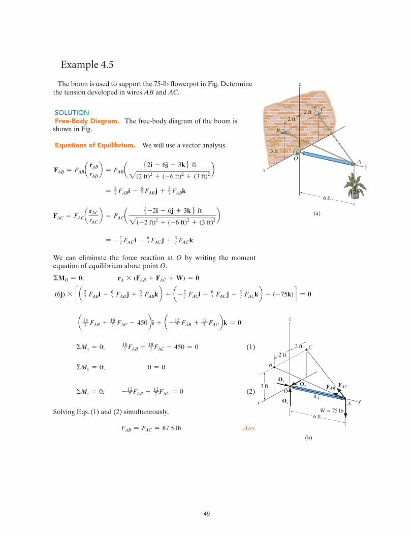
The boom is used to support the 75-lb flowerpot in Fig . Determine the tension developed in wires AB and AC .
SOLUTION Free-Body Diagram. The free-body diagram of the boom is shown in Fig.
Equations of Equilibrium. We will use a vector analysis.
FAB = FABarAB
rABb = FABa
52i - 6j + 3k6 ft
2(2 ft)2 + (-6 ft)2 + (3 ft)2b
= 27
67
37FABi - FABj + FABk
FAC = FACarAC
rACb = FACa
5-2i - 6j + 3k6 ftb
27
67
37
2(-2 ft)2 + (-6 ft)2 + (3 ft)2
= - FAC i - FACj + FACk
We can eliminate the force reaction at O by writing the moment equation of equilibrium about point O .
�MO = 0; rA * (FAB + FAC + W) = 0
27
67 (6j) * c a FABi - FAB j + 3
727
67
37FABkb + a - FACi - FACj + FACkb + (-75k) d = 0
a 718 FAB + 7
18 FAC - 450b i + a - 712 FAB + 7
12 FACbk = 0
718 FAB + 7
18 FAC - 450 = 0 (1)
0 = 0
�Mx = 0;
�My = 0;
�Mz = 0; - 712 FAB + 7
12 FAC = 0 (2)
Solving Eqs. ( 1 ) and ( 2 ) simultaneously,
FAB = FAC = 87.5 lb Ans .
B
A
(b)
6 ft
x y
O
z
3 ft
2 ft
2 ft
W � 75 lb
Oz
OyOx
C
rA
FABFAC
xy
OA
z
6 ft
(a)
3 ft
2 ft2 ft
B
C
Example 4.5
49

Chapter 5
Trusses
Contents
Introduction
Definition of a Truss
Simple Trusses
Analysis of Trusses by the Method of Joints
Sample Problem 5.1
Sample Problem 5.2
Sample Problem 5.3
Analysis of Trusses by the Method of Sections
Sample Problem 5.4
50

5.1 Introduction • For the equilibrium of structures made of several connected parts, the internal forces
as well the external forces are considered.• In the interaction between connected parts, Newton’s 3
rd Law states that the forces of
action and reaction between bodies in contact have the same magnitude, same line ofaction, and opposite sense.
• Three categories of engineering structures are considered:a) Frames: contain at least one multi-force member, i.e., member acted upon by 3
or more forces.b) Trusses: formed from two-force members, i.e., straight members with end point
connectionsc) Machines: structures containing moving parts designed to transmit and modify
forces.
51

5.2 Definition of a Truss
• A truss consists of straight members connected at joints. No member is continuousthrough a joint.
• Most structures are made of several trussesjoined together to form a space framework.Each truss carries those loads which act in itsplane and may be treated as a two-dimensional structure.
• Bolted or welded connections are assumed tobe pinned together. Forces acting at themember ends reduce to a single force and nocouple. Only two-force members areconsidered.
• When forces tend to pull the member apart, it is intension. When the forces tend to compress themember, it is in compression.
Members of a truss are slender and not capable of supporting large lateral loads. Loads must be applied at the joints.
52

5.3 Types of Trusses
53

5.4 Simple Trusses
• A simple truss is constructed by successively addingtwo members and one connection to the basic triangulartruss.
• In a simple truss, m = 2n - 3 where m is the totalnumber of members and n is the number of joints.
5.5 Analysis of Trusses by the Method of Joints • Dismember the truss and create a
freebody diagram for each member andpin.
54

• The two forces exerted on eachmember are equal, have thesame line of action, andopposite sense.
• Forces exerted by a member onthe pins or joints at its ends aredirected along the member andequal and opposite.
• Conditions of equilibrium onthe pins provide 2n equationsfor 2n unknowns. For a simpletruss, 2n = m+3. May solve form member forces and 3 reaction forces at the supports.
• Conditions for equilibrium for the entire truss provide 3 additional equations whichare not independent of the pin equations.
55

Determine the force in each member of the truss shown in Fig. a and indicate whether the members are in tension or compression.
SOLUTION Since we should have no more than two unknown forces at the joint and at least one known force acting there, we will begin our analysis at joint B .
Joint B. The free-body diagram of the joint at B is shown in Fig. b . Applying the equations of equilibrium, we have
+S �Fx = 0;
+ c�Fy = 0;
500 N - FBC sin 45� = 0 FBC = 707.1 N (C) Ans.
FBC cos 45� - FBA = 0 FBA = 500 N (T) Ans.
Since the force in member BC has been calculated, we can proceed to analyze joint C to determine the force in member CA and the support reaction at the rocker.
Joint C. From the free-body diagram of joint C , Fig. c , we have
+S �Fx = 0; -FCA + 707.1 cos 45� N = 0 FCA = 500 N (T) Ans.
+ c�Fy = 0; Cy - 707.1 sin 45� N = 0 Cy = 500 N Ans.
Joint A. Although it is not necessary, we can determine the components of the support reactions at joint A using the results of FCA
and FBA . From the free-body diagram, Fig. d , we have
+S �Fx = 0; Ax = 500 N
+ c�Fy = 0;
500 N - Ax = 0
500 N - Ay = 0 Ay = 500 N
B
2 m
2 m
500 N
A C
(a)
45�
(b)
B
45�
500 N
FBCFBA
(c)
45�707.1 N
FCAC
Cy
(d)
A
FBA � 500 N
FCA � 500 N
Ay
Ax
(e)
B
45�
500 N
A 45�500 N
500 N
500 N500 N
C
707.1 N
707.1 N
500 N500 N
Tension
CompressionT
ensi
on
Sample Problem 5.1
56
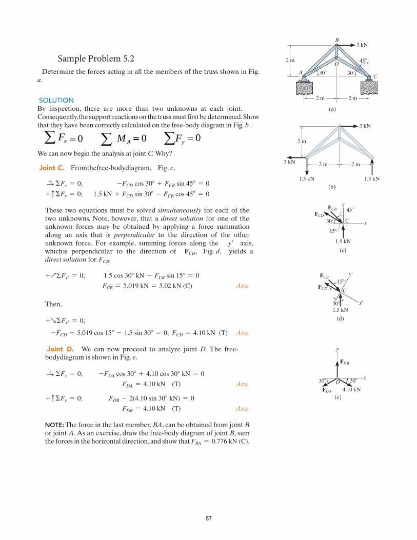
Determine the forces acting in all the members of the truss shown in Fig. a .
SOLUTION By inspection, there are more than two unknowns at each joint. Consequently, the support reactions on the truss must first be determined. Show that they have been correctly calculated on the free-body diagram in Fig. b .
We can now begin the analysis at joint C. Why?
Joint C. From the free-body diagram, Fig. c ,
+S �Fx = 0; -FCD cos 30� + FCB sin 45� = 0
+ c �Fy = 0; 1.5 kN + FCD sin 30� - FCB cos 45� = 0
These two equations must be solved simultaneously for each of the two unknowns. Note, however, that a direct solution for one of the unknown forces may be obtained by applying a force summation along an axis that is perpendicular to the direction of the other unknown force. For example, summing forces along the y� axis, which is perpendicular to the direction of FCD, Fig. d, yields a direct solution for FCB.
+Q�Fy� = 0; 1.5 cos 30� kN - FCB sin 15� = 0
FCB = 5.019 kN = 5.02 kN (C) Ans.
Then,
+R�Fx� = 0;
-FCD + 5.019 cos 15� - 1.5 sin 30� = 0; FCD = 4.10 kN (T) Ans.
Joint D. We can now proceed to analyze joint D . The free-body diagram is shown in Fig. e .
+S �Fx = 0;
Ans.
+ c�Fy = 0;
-FDA cos 30� + 4.10 cos 30� kN = 0
FDA = 4.10 kN (T)
FDB - 2(4.10 sin 30� kN) = 0
FDB = 4.10 kN (T) Ans.
NOTE: The force in the last member, BA , can be obtained from joint Bor joint A. As an exercise, draw the free-body diagram of joint B , sum the forces in the horizontal direction, and show that FBA = 0.776 kN (C).
2 m 2 m
D
B
CA
2 m
3 kN
(a)
45�
30�30�
2 m 2 m
2 m
3 kN
(b)
3 kN
1.5 kN1.5 kN
x
FCBFCD
1.5 kN
C
45�
30�
y
15�
(c)
x¿
FCB
FCD
1.5 kN
C
30�
y¿15�
(d)
(e)
y
x
FDB
FDA 4.10 kN
30�30� D
Sample Problem 5.2
57
= 0 = 0Ax MF = Fy = 0
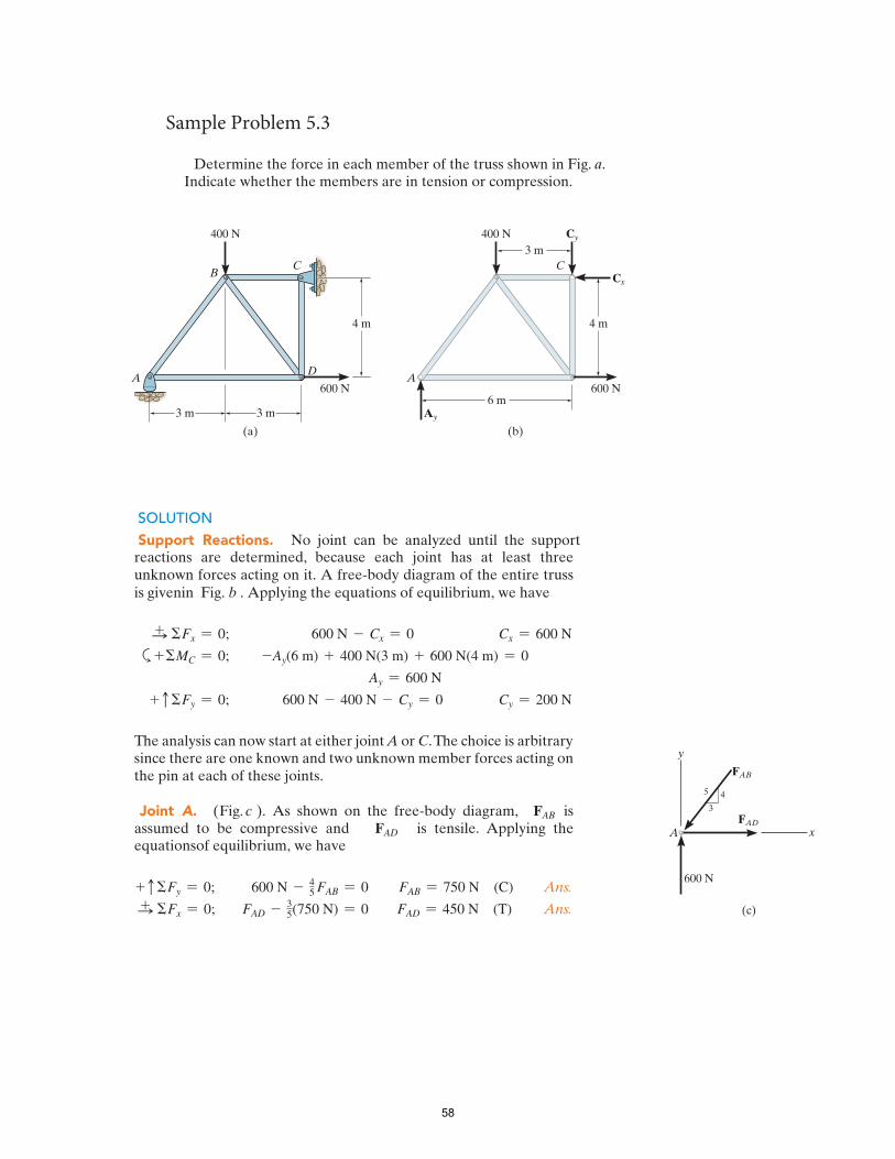
Determine the force in each member of the truss shown in Fig. a . Indicate whether the members are in tension or compression.
4 m
(a)
3 m
400 N
BC
DA
3 m
600 N
4 m
(b)
400 N
C
A
6 m600 N
3 m
Ay
Cy
Cx
SOLUTION Support Reactions. No joint can be analyzed until the support reactions are determined, because each joint has at least three unknown forces acting on it. A free-body diagram of the entire truss is given in Fig. b . Applying the equations of equilibrium, we have
+S �Fx = 0; 600 N - Cx = 0 Cx = 600 N
a+�MC = 0; -Ay(6 m) + 400 N(3 m) + 600 N(4 m) = 0
+ c�Fy = 0;
Ay = 600 N
600 N - 400 N - Cy = 0 Cy = 200 N
The analysis can now start at either joint A or C . The choice is arbitrary since there are one known and two unknown member forces acting on the pin at each of these joints.
Joint A. ( Fig. c ). As shown on the free-body diagram, FAB is assumed to be compressive and FAD is tensile. Applying the equations of equilibrium, we have
45 Ans.
+S+ c�Fy = 0;
�Fx = 0; 35
600 N - FAB = 0
FAD - (750 N) = 0
FAB = 750 N (C)
FAD = 450 N (T) Ans.
Sample Problem 5.3
3
45
x
y
FAB
FAD
600 N
(c)
A
58

* The proper sense could have been determined by inspection, prior to applying �Fx = 0.
Joint D. ( Fig. 6–10 d ). Using the result for FAD and summing forces in the horizontal direction, Fig. d , we have
+S �Fx = 0; 35-450 N + FDB + 600 N = 0 FDB = -250 N
The negative sign indicates that FDB acts in the opposite sense to that shown in Fig. d . * Hence,
FDB = 250 N (T) Ans.
To determine FDC, we can either correct the sense of FDB on the free-body diagram, and then apply �Fy = 0, or apply this equation and retain the negative sign for FDB, i.e.,
+ c � Fy = 0; -FDC - ( 250(4/5) N) = 0 FDC = 200 N (C) Ans.
Joint C. ( Fig. e ). +S �Fx = 0; FCB - 600 N = 0 FCB = 600 N (C) Ans.
+ c�Fy = 0; 200 N - 200 N K 0 (check)
NOTE: The analysis is summarized in Fig. f , which shows the free-body diagram for each joint and member.
3
4 5
x
y
FDB
600 N
(d)
FDC
450 N D
750 N 250 N
600 N
400 N
Compression 600 N
200 N
600 N
200 N
Tension
Com
pressionCompr
essio
n
750 N
450 N
600 N
ATension
450 N
250 N 200 N
600 ND
CB
x
y
200 N
(e)
C 600 N
200 N
FCB
(f)
59

5.6 Analysis of Trusses by the Method of Sections • When the force in only one member or the
forces in a very few members are desired,the method of sections works well.• To determine the force in member BD,
pass a section through thetruss as shown and create a freebody diagram for the left segment.
• That segment of the sectionedtruss has the least number of forcesacting on it.
• With only three members cut by thesection, the equations for staticequilibrium may be applied todetermine the unknown member forces,including F
BD.
60

Sample Problem 5.4
Determine the force in members FH, GH, and GI.
SOLUTION: • Take the entire truss as a rigid
body. Apply the conditionsfor static equilibrium to solvefor the reactions at A and L.
• Pass a section throughmembers FH, GH, and GIand take the right-handsection as a free body.
• Apply the conditions for static equilibrium to determine the desired member forces.
61
30
Note that: no reaction at support point A in x-direction, only in y-direction, because there is no any axial force on the whole truss free body in x-direction.
� Fx = 0; Ax = 0

( )( ) ( )( ) ( ) 0m 33.5m 5kN 1m 10kN 7.500
+==−−
=∑
GI
GI
H
FF
M( )( ) ( )( ) ( )
1313..1313 kkNN (T)0m 33.5m 5kN 1m 10kN 7.50
0
+==−−
=∑
GI
GI
H
FF
M
( )( ) ( )( ) ( )( )( )( ) 0m 8cos
m 5kN 1m 10kN 1m 15kN 7.50
07.285333.0m 15m 8tan
−==+
−−=
°====
∑
FH
FH
G
FF
MGLFG
α
αα
( )( ) ( )( ) ( )( )( )( )
1313..8282 kkNN (C)0m 8cos
m 5kN 1m 10kN 1m 15kN 7.50
07.285333.0m 15m 8tan
−==+
−−=
°====
∑
FH
FH
G
FF
MGLFG
α
αα
( )
( )( ) ( )( ) (m 5kN 1m 10kN 10
15.439375.0m 8
m 5tan32
−=++
=
°====
∑
GH
GH
L
FF
M
HIGI ββ
( )
( )( ) ( )( ) (11..373711 kkNN (C)
m 5kN 1m 10kN 10
15.439375.0m 8
m 5tan32
−=++
=
°====
∑
GH
GH
L
FF
M
HIGI
cocossββ ))((15 m)
ββ
62
To get the length of member HI:HI / 8 = LI / LG = 10 / 15 = 2 / 3HI = 2/3 (8)

Chapter 6
Friction
Contents
Introduction
Laws of Dry Friction.
Coefficients of Friction.
Angles of Friction
Problems Involving Dry Friction
Sample Problem 6.1 rough plane
Sample Problem 6.2 rough pully
63

6.1 Introduction • The distinction between frictionless and rough is, therefore, a matter of degree.
• In preceding chapters, it was assumed that surfaces in contact were eitherfrictionless (surfaces could move freely with respect to each other) or rough(tangential forces prevent relative motion between surfaces).
• Actually, no perfectly frictionless surface exists. For two surfaces in contact,tangential forces, called friction forces, will develop if one attempts to move onerelative to the other.
• However, the friction forces are limited in magnitude and will not prevent motionif sufficiently large forces are applied.
• There are two types of friction: dry or Coulomb friction and fluid friction. Fluidfriction applies to lubricated mechanisms. The present discussion is limited to dryfriction between nonlubricated surfaces.
6.2 The Laws of Dry Friction. Coefficients of Friction • Block of weight W placed on horizontal surface.
Forces acting on block are its weight and reaction ofsurface N.
• Small horizontal force P applied to block. For blockto remain stationary, in equilibrium, a horizontalcomponent F of the surface reaction is required. F is astatic-friction force.
• As P increases, the static-friction force F increases aswell until it reaches a maximum value F
m.
64

NF sm µ= NF sm µ=
• Further increase in P causes the block tobegin to move as F drops to a smallerkinetic-friction force F
k.
NF kk µ= NF kk µ=
• Maximum static-friction force:NF sm µ= NF sm µ=
• Kinetic-friction force:
sk
kk NFµµ
µ75.0≅
=
sk
kk NFµµ
µ75.0≅
=
• Maximum static-friction force and kinetic-friction force are:
proportional to normal force dependent on type and condition of contact surfaces independent of contact area
65

• Four situations can occur when a rigid body is in contact with a horizontal surface:
• Nofriction,(Px = 0)
• Motionimpending,(Px = Fm)
• Nomotion,(Px < Fm)
• Motion,(Px > Fm)
66

6.3 Angles of Friction It is sometimes convenient to replace normal force N and friction force F by their resultant R:
• Nofriction
• Motionimpending
67

• Consider block of weight W resting on board with variableinclination angle q.
68

Sample Problem 6.1
A 100 lb force acts as shown on a 300 lb block placed on an inclined plane. The coefficients of friction between the block and plane are µ
s = 0.25 and µ
k =
0.20. Determine whether the block is in equilibrium and find the value of the friction force. SOLUTION:
• Determine values of friction force and normalreaction force from plane required to maintainequilibrium.
:0=∑ xF :0=∑ xF
lb 80−=F lb 80−=F
:0=∑ yF :0=∑ yF
lb 240=N lb 240=N
( ) 0lb 300 - lb 100 53 =− F
( ) 0lb 300 - 54 =N
69
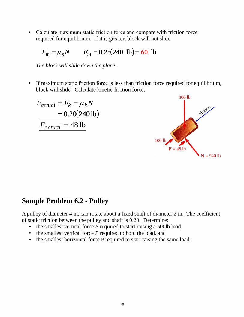
• Calculate maximum static friction force and compare with friction forcerequired for equilibrium. If it is greater, block will not slide.
FFmm == µµ ss NN FFmm == 00..2525((242400 lblb)) == 60 lblb
The block will slide down the plane.
• If maximum static friction force is less than friction force required for equilibrium,block will slide. Calculate kinetic-friction force.
( )lb 24020.0=== NFF kkactual µ( )lb 24020.0=== NFF kkactual µ
Sample Problem 6.2 - Pulley
A pulley of diameter 4 in. can rotate about a fixed shaft of diameter 2 in. The coefficient of static friction between the pulley and shaft is 0.20. Determine:
• the smallest vertical force P required to start raising a 500lb load,• the smallest vertical force P required to hold the load, and• the smallest horizontal force P required to start raising the same load.
lb 48=actualF
70

The perpendicular distance from center O of pulley to line of action of R is
rr ff == rr ssininϕϕ ss ≈≈ rrµµ ss rr ff ≈≈ ((11 inin..))00..2020 == 00..2020inin..
Sum moments about displaced contact point B to find P.
( )( ) ( ) 0in.80.1lb500in.20.2:0 =−=∑ PM B ( )( ) ( ) 0in.80.1lb500in.20.2:0 =−=∑ PM B
lb611=P lb611=P Impending motion is counter-clockwise as load is held stationary with smallest force P. Sum moments about C to find P.
The perpendicular distance from center O of pulley to line of action of R is again 0.20 in. Summing moments about C,
( )( ) ( ) 0in.20.2lb500in.80.1:0 =−=∑ PMC ( )( ) ( ) 0in.20.2lb500in.80.1:0 =−=∑ PMClb409=P lb409=P
• With the load on the left and force P actinghorizontally to the right, impending motion isclockwise to raise load. Utilize a force triangle tofind P.
( )°=
===
1.4
0707.02in.2
in.20.0sin
θ
θODOE
( )°=
===
1.4
0707.02in.2
in.20.0sin
θ
θODOE
From the force triangle,
( ) ( ) °=−°= 9.40cotlb50045cot θWP ( ) ( ) °=−°= 9.40cotlb50045cot θWPlb577=P lb577=P
SOLUTION: • With the load on the left and force P on the right, impending motion is clockwise to
raise load. Sum moments about displaced contact point B to find P.
71

Chapter 7
Centroids and Centers of Gravity
Contents
Introduction
Center of Gravity of a 2D Body
Centroids and First Moments of Areas and Lines
Centroids of Common Shapes of Areas
Centroids of Common Shapes of Lines
Composite Plates and Areas
Sample Problem 7.1
Determination of Centroids by Integration
Center of Gravity of a 3D Body: Centroid of a Volume
Centroids of Common 3D Shapes
Composite 3D Bodies
Sample Problem 7.2
72

7.1 Introduction
• The earth exerts a gravitational force on each of the particles forming a body.These forces can be replaced by a single equivalent force equal to the weight of thebody and applied at the center of gravity for the body.
• The centroid of an area is analogous to the center of gravity of a body. Theconcept of the first moment of an area is used to locate the centroid.
7.2 Center of Gravity of a 2D Body • Center of gravity of a plate and a wire
∫
∑∑∫
∑∑
=
∆=
=
∆=
dWy
WyWyMdWx
WxWxM
y
y
∫
∑∑∫
∑∑
=
∆=
=
∆=
dWy
WyWyMdWx
WxWxM
y
y
7.3 Centroids and First Moments of Areas and Lines • Centroid of an area
( ) ( )
xQdAyAy
y
QdAxAx
dAtxAtx
dWxWx
x
y
respect toh moment witfirst
respect toh moment witfirst
=
==
=
==
=
=
∫
∫∫∫
γγ( ) ( )
xQdAyAy
y
QdAxAx
dAtxAtx
dWxWx
x
y
respect toh moment witfirst
respect toh moment witfirst
=
==
=
==
=
=
∫
∫∫∫
γγ
73

• Centroid of a line
( ) ( )
∫∫∫∫
=
=
=
=
dLyLy
dLxLx
dLaxLax
dWxWx
γγ( ) ( )
∫∫∫∫
=
=
=
=
dLyLy
dLxLx
dLaxLax
dWxWx
γγ
7.4 First Moments of Areas • An area is symmetric with respect to an axis BB’ if for every point P
there exists a point P’ such that PP’ is perpendicular to BB’ and isdivided into two equal parts by BB’.
• The first moment of an area with respect to a line of symmetry iszero.
• If an area possesses a line of symmetry, its centroid lies on thataxis
• If an area possesses two lines of symmetry, its centroid lies attheir intersection.
• An area is symmetric with respect to a center O if for everyelement dA at (x,y) there exists an area dA’ of equal area at (-x,-y).
• The centroid of the area coincides with the center ofsymmetry.
74

Table 7.1 Centroids of Common Shapes of Areas
75

Table 7.1 Centroids of Common Shapes of Areas (continue)
Composite Plates and Areas • Composite plates
∑∑∑∑
==
WyWYWxWX
∑∑∑∑
==
WyWYWxWX
• Composite area
∑∑∑∑
==
AyAYAxAX
∑∑∑∑
==
AyAYAxAX
Sample Problem 7.1
For the plane area shown, determine the first moments with respect to the x and y axes and the location of the centroid.
76

SOLUTION:
Divide the area into a triangle, rectangle, and semicircle with a circular cutout.
Calculate the first moments of each area with respect to the axes.
Find the total area and first moments of the triangle, rectangle, and semicircle. Subtract the area and first moment of the circular cutout.
Compute the coordinates of the area centroid by dividing the first moments by the total area.
• Find the total area and first moments of the triangle, rectangle, and semicircle.Subtract the area and first moment of the circular cutout.
33
33
mm107.757
mm102.506
×+=
×+=
y
x
Q
Q33
33
mm107.757
mm102.506
×+=
×+=
y
x
Q
Q
77

• Compute the coordinates of the area centroid bydividing the first moments by the total area.
23
33
mm1013.828mm107.757
×
×+==
∑∑
AAxX 23
33
mm1013.828mm107.757
×
×+==
∑∑
AAxX
mm 8.54=X mm 8.54=X
mm 6.36=Y mm 6.36=Y
7.5 Center of Gravity of a 3D Body: Centroid of a Volume
• Center of gravity G
( )∑ ∆−=− jWjW ( )∑ ∆−=− jWjW
( ) ( )[ ]( ) ( ) ( )jWrjWr
jWrjWr
G
G
−×∆=−×
∆−×=−×
∑∑( ) ( )[ ]
( ) ( ) ( )jWrjWrjWrjWr
G
G
−×∆=−×
∆−×=−×
∑∑
∫∫ == dWrWrdWW G∫∫ == dWrWrdWW G
78

• Results are independent of body orientation,∫∫∫ === zdWWzydWWyxdWWx ∫∫∫ === zdWWzydWWyxdWWx
• For homogeneous bodies,
dVdWVW γγ == and dVdWVW γγ == and
∫∫∫ === zdVVzydVVyxdVVx ∫∫∫ === zdVVzydVVyxdVVx
Centroids of Common 3D Shapes
79

Composite 3D Bodies • Moment of the total weight concentrated at the center of gravity G is equal to the sum
of the moments of the weights of the component parts.
∑∑∑∑∑∑ === WzWZWyWYWxWX ∑∑∑∑∑∑ === WzWZWyWYWxWX• For homogeneous bodies,
∑∑∑∑∑∑ === VzVZVyVYVxVX ∑∑∑∑∑∑ === VzVZVyVYVxVX
Sample Problem 7.2 Locate the center of gravity of the steel machine element.
The diameter of each hole is 1 in.
SOLUTION:
Form the machine element from a rectangular parallelepiped and a quarter cylinder and then subtracting two 1-in. diameter cylinders.
80

( ) ( )34 in .2865in 08.3== ∑∑ VVxX ( ) ( )34 in .2865in 08.3== ∑∑ VVxX in. 577.0=X in. 577.0=X
( ) ( )34 in .2865in 5.047−== ∑∑ VVyY ( ) ( )34 in .2865in 5.047−== ∑∑ VVyY in. 577.0=Y in. 577.0=Y
( ) ( )34 in .2865in .6181== ∑∑ VVzZ ( ) ( )34 in .2865in .6181== ∑∑ VVzZ in. 577.0=Z in. 577.0=Z
81
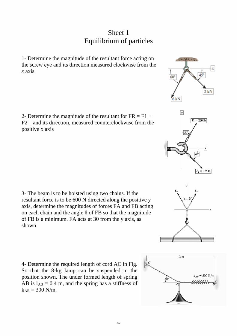
Sheet 1 Equilibrium of particles
1- Determine the magnitude of the resultant force acting onthe screw eye and its direction measured clockwise from thex axis.
2- Determine the magnitude of the resultant for FR = F1 +F2 and its direction, measured counterclockwise from thepositive x axis
3- The beam is to be hoisted using two chains. If theresultant force is to be 600 N directed along the positive yaxis, determine the magnitudes of forces FA and FB actingon each chain and the angle θ of FB so that the magnitudeof FB is a minimum. FA acts at 30 from the y axis, asshown.
4- Determine the required length of cord AC in Fig.So that the 8-kg lamp can be suspended in theposition shown. The under formed length of springAB is lAB = 0.4 m, and the spring has a stiffness ofkAB = 300 N/m.
82
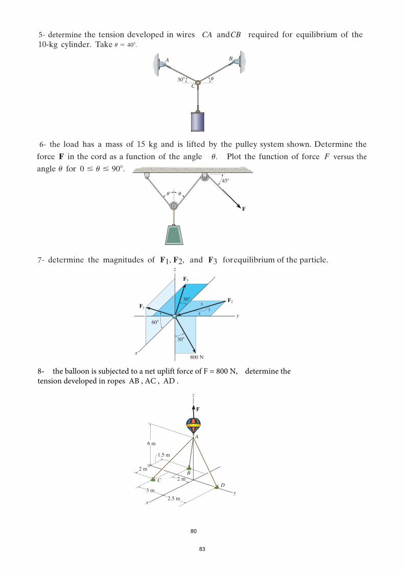
5- determine the tension developed in wires CA and CB required for equilibrium of the10-kg cylinder. Take u = 40� .
30�
A B
Cu
6- the load has a mass of 15 kg and is lifted by the pulley system shown. Determine the
force F in the cord as a function of the angle u. Plot the function of force F versus theangle u for 0 … u … 90�.
uu
F
45�
7- determine the magnitudes of F1, F2, and F3 for equilibrium of the particle.
30�
F3
F2F1
30�
y
x
z
60�
800 N
34
5
8-- the balloon is subjected to a net uplift force of F = 800 N, determine thetension developed in ropes AB , AC , AD .
z
y
D
A
F
C
x
6 m
2 m
2 m
3 m
2.5 m
1.5 m
B
80
83

Sheet (2)
Equivalent system force
1. If θ = 45o, determine the moment
produced by the 4-kN force about point
A.
2. The handle of the hammer is subjected
to the force of F = 20 lb. Determine the moment
of this force about the point A.
3. The 70-N force acts on the end of the pipe at B.
Determine (a) the moment of this force about
point A, and (b) the magnitude and direction of
a horizontal force, applied at C, which produces
the same moment. Take θ = 60°.
84

4. Determine the resultant moment produced by the two forces about point O. Express
the result as a Cartesian vector.
5. Determine the magnitude of the moments of the force F about the x, y, and z axes.
Solve the problem using a Cartesian vector approach.
85

6. Determine the magnitude of the moment that
the force F exerts about the y axis of the
shaft. Solve the problem using a Cartesian
vector approach and using a scalar approach.
7. Determine the resultant couple
moment acting on the beam. Solve
the problem two ways: (a) sum
moments about point O; and (b)
sum moments about point A.
8. Determine the required magnitude of force F
if the resultant couple moment on the frame is
200 lb. ft, clockwise.
8486

Sheet 3
Equilibrium of rigid Body
1. Determine the horizontal and vertical components
of reaction at the pin A and the tension developed
in cable BC used to support the steel frame.
2. The articulated crane boom has a weight of
125 lb and center of gravity at G. If it
supports a load of 600 lb, determine the force
acting at the pin A and the force in the
hydraulic cylinder BC when the boom is in
the position shown.
3. Determine the horizontal and vertical
components of reaction at the pin A and the
reaction of the smooth collar B on the rod.
87

4. The uniform rod AB has a weight of 15 lb.
Determine the force in the cable when the rod is
in the position shown.
5. Determine the horizontal and vertical
components of reaction at C and the tension in
the cable AB for the truss
6. Determine the tension developed in
cables AB, CD, and EF. Neglect the
weight of the plate.
88

7. The crane boom AB which has a weight of
650 lb and center of gravity at G. The boom
is supported by a pin at A and cable BC. The
load of 1250 lb is suspended from a cable
attached at B. Determine the horizontal and
vertical components of reaction at A and the
tension in cable BC on the boom.
8. The member ABC supported by a smooth collar at A, roller at B, and short link CD.
Determine the normal reactions at A and B and the force in link CD acting on the
member. Determine the normal reactions at A and B and the force in link CD acting
on the member
9. The shaft is supported by three
smooth journal bearings at A, B,
and C. Determine the components
of reaction at these bearings.
89
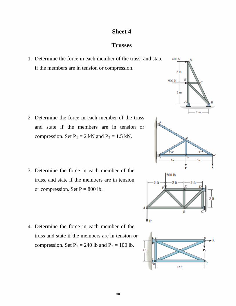
Sheet 4
Trusses
1. Determine the force in each member of the truss, and state
if the members are in tension or compression.
2. Determine the force in each member of the truss
and state if the members are in tension or
compression. Set P1 = 2 kN and P2 = 1.5 kN.
3. Determine the force in each member of the
truss, and state if the members are in tension
or compression. Set P = 800 lb.
4. Determine the force in each member of the
truss and state if the members are in tension or
compression. Set P1 = 240 lb and P2 = 100 lb.
8890

5. Determine the force in each member of the truss
and state if the members are in tension or
compression. The load has a mass of 40 kg.
6. Determine the force developed in members
BC and CH of the roof truss and state if the
members are in tension or compression.
7. Determine the force in members BC, CG, and
GF of the Warren truss. Indicate if the members
are in tension or compression.
8. The Howe bridge truss is subjected to
the loading shown. Determine the force
in members HD, CD, and GD, and state
if the members are in tension or
compression.
8991
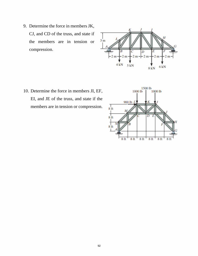
9. Determine the force in members JK,
CJ, and CD of the truss, and state if
the members are in tension or
compression.
10. Determine the force in members JI, EF,
EI, and JE of the truss, and state if the
members are in tension or compression.
92

Sheet 5
Friction
1. Determine the minimum horizontal force P
required to hold the crate from sliding down the
plane. The crate has a mass of 50 kg and the
coefficient of static friction between the crate and
the plane is µs = 0.25
2. If the coefficient of static friction at A is µs = 0.4
and the collar at B is smooth so it only exerts a
horizontal force on the pipe, determine the
minimum distance x so that the bracket can
support the cylinder of any mass without
slipping. Neglect the mass of the bracket.
3. The coefficients of static and kinetic friction
between the drum and brake bar are µs = 0.4
and µk = 0.3 , respectively. If M = 50 N.m
and P = 85 N. determine the horizontal and
vertical components of reaction at the pin O.
Neglect the weight and thickness of the
brake.The drum has a mass of 25 kg
9193

4. A man attempts to support a stack of books
horizontally by applying a compressive
force of F = 120 N to the ends of the stack
with his hands. If each book has a mass of
0.95 kg, determine the greatest number of
books that can be supported in the stack. The coefficient of static friction between
the man’s hands and a book is (µs)h = 0.6 and between any two books (µs)b = 0.4.
5. The uniform I0-kg ladder rests against the
smooth wall at B, and the end A rests on the rough
horizontal plane for which the coefficient of static
friction is µs= 0.3. Determine the angle of
inclination θ of the ladder and the normal reaction
at B if the ladder is on the verge of slipping.
6. The uniform crate has a mass of 20 kg. If
a force P = 80 N is applied to the crate,
determine if it remains in equilibrium.
The coefficient of static friction is µs=
0.3.
0.8 mP � 80 N
0.2 m
30�
94

7. Blocks A and B Blocks A have a mass of 3 Kg and
9 Kg, and are connected to the weightless links as
shown. Determine the largest vertical force P that
can be applied to the pin C without causing any
movement. The coefficient of static friction between
the blocks and the contacting surfaces is µs= 0.3.
8. Beam AB is subjected to a uniform load of
200 N/m and is supported at B by post BC.
If the coefficient of static friction at B and
C are µB= 0.2 and µc= 0.5, determine the
force P needed to pull the post out from
under the beam.
200 N/m
0.75 m
B
P
4 m
0.25 mC
A
95

Sheet 6 Centroid
1. Locate the centroid of (�̅�𝑥 , 𝑦𝑦�) of the uniform wire bent inthe shape shown.
2. Locate the centroid 𝑦𝑦 �of the channel’s cross-sectional area.
3. Locate the centroid (�̅�𝑥 , 𝑦𝑦�) of the compositearea.
4. Locate the centroid (�̅�𝑥 , 𝑦𝑦�) of the compositearea.
96

5. Locate the centroid Ix of the given cross-sectionalarea.
6. Locate the centroid (�̅�𝑥 , 𝑦𝑦�) of the compositearea
7. Locate the centroid Ix of the given cross-sectional area
8. Locate the centroid Ix of the given cross-sectional area
97

9. Locate the Iy of the given cross-sectional area
10. Determine Ix and Iy for the given cross-sectional area
11. Locate the Iy of the given cross-sectional area
98