lecture notes - mineralogy - stereographic projections · lecture notes - mineralogy -...
TRANSCRIPT
Lecture Notes - Mineralogy - Stereographic Projections
• The stereographic projection is a device use by mineralogists and structural geologists torepresent 3-dimensional information in two dimensions. Mineralogists use a Wulff stereonet,which is constructed from a simple geometric recipe. Structural geologists use a Schmidtstereonet, which is constructed from a more complicated algorithm designed so that each“square” on the net has the same area.
• The Wulff sterographic projection is constructed by projecting points and lines from the surfaceof a sphere onto a horizontal plane passing through the center of the sphere. The projection isaccomplished by connecting the bottom point of the sphere (the south pole) with the points onthe upper (northern) hemisphere. Each point from the upper hemisphere plots where the line ofprojection passes through the plane of projection (the equitorial plane). Points on the bottom(southern) hemisphere can be projected “negatively” using the upper (north) pole as the point ofprojection. (Structural geologists normally represent the bottom hemisphere on their Schmidtstereographic projections.)
• The stereonet itself shows the projection of great circles and small circles. A great circle is theline of intersection with the surface of a sphere of a plane that passes through the center of thesphere. A small circle marks the path in space of a point on the surface of a sphere that isrotating about an axis. Lines of longitude on the earth are great circles; lines of latitude are smallcircles. These reference lines are useful in the manipulation of crystallographic data.
• All of the symmetry elements of a crystal class and their relative positions may be shown con-veniently on a sterographic projection. The symmetry point of the point group is placed in thecenter of the sphere of projection. Intersections with the upper hemisphere of the symmetryelements of the point group (rotation axes, rotoinversion axes, and/or mirror planes) are pro-jected onto the stereonet plane. By convention (Klein and Hurlbut, p.62), the c-axis is chosen asthe vertical axis, the b-axis is east-west, and the a-axis is north-south. Please follow this conven-tion, but be aware that not all authors follow it.
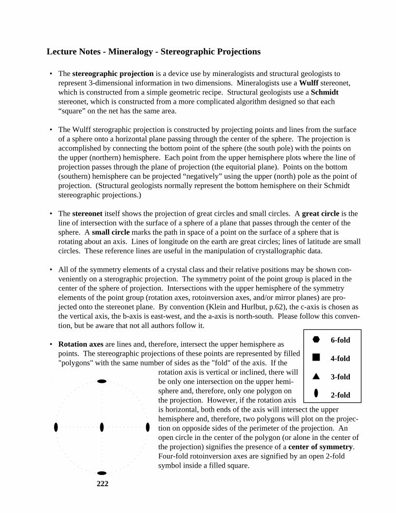
• Rotation axes are lines and, therefore, intersect the upper hemisphere aspoints. The stereographic projections of these points are represented by filled"polygons" with the same number of sides as the "fold" of the axis. If the
rotation axis is vertical or inclined, there willbe only one intersection on the upper hemi-sphere and, therefore, only one polygon onthe projection. However, if the rotation axisis horizontal, both ends of the axis will intersect the upperhemisphere and, therefore, two polygons will plot on the projec-tion on opposide sides of the perimeter of the projection. Anopen circle in the center of the polygon (or alone in the center ofthe projection) signifies the presence of a center of symmetry.Four-fold rotoinversion axes are signified by an open 2-foldsymbol inside a filled square.
4-fold
3-fold
2-fold
6-fold
222
Stereographic Projections 2
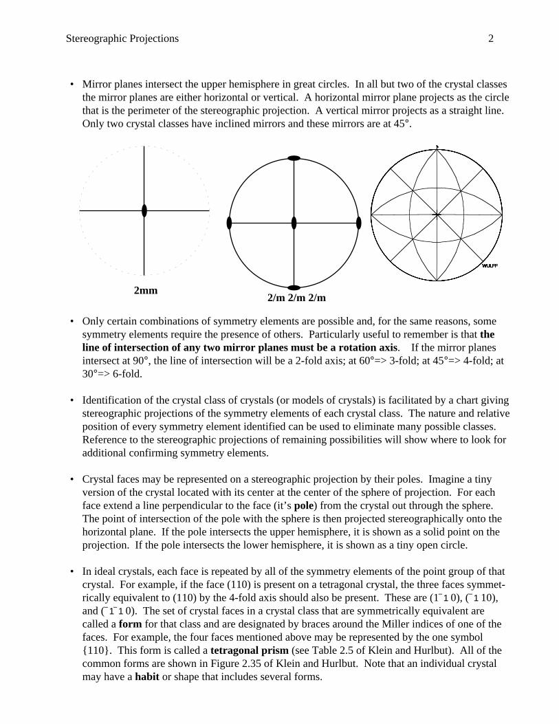
• Mirror planes intersect the upper hemisphere in great circles. In all but two of the crystal classesthe mirror planes are either horizontal or vertical. A horizontal mirror plane projects as the circlethat is the perimeter of the stereographic projection. A vertical mirror projects as a straight line.Only two crystal classes have inclined mirrors and these mirrors are at 45°.
• Only certain combinations of symmetry elements are possible and, for the same reasons, somesymmetry elements require the presence of others. Particularly useful to remember is that theline of intersection of any two mirror planes must be a rotation axis. If the mirror planesintersect at 90°, the line of intersection will be a 2-fold axis; at 60°=> 3-fold; at 45°=> 4-fold; at30°=> 6-fold.
• Identification of the crystal class of crystals (or models of crystals) is facilitated by a chart givingstereographic projections of the symmetry elements of each crystal class. The nature and relativeposition of every symmetry element identified can be used to eliminate many possible classes.Reference to the stereographic projections of remaining possibilities will show where to look foradditional confirming symmetry elements.
• Crystal faces may be represented on a stereographic projection by their poles. Imagine a tinyversion of the crystal located with its center at the center of the sphere of projection. For eachface extend a line perpendicular to the face (it’s pole) from the crystal out through the sphere.The point of intersection of the pole with the sphere is then projected stereographically onto thehorizontal plane. If the pole intersects the upper hemisphere, it is shown as a solid point on theprojection. If the pole intersects the lower hemisphere, it is shown as a tiny open circle.
• In ideal crystals, each face is repeated by all of the symmetry elements of the point group of thatcrystal. For example, if the face (110) is present on a tetragonal crystal, the three faces symmet-rically equivalent to (110) by the 4-fold axis should also be present. These are (11 0), (1 10),and (11 0). The set of crystal faces in a crystal class that are symmetrically equivalent arecalled a form for that class and are designated by braces around the Miller indices of one of thefaces. For example, the four faces mentioned above may be represented by the one symbol{110}. This form is called a tetragonal prism (see Table 2.5 of Klein and Hurlbut). All of thecommon forms are shown in Figure 2.35 of Klein and Hurlbut. Note that an individual crystalmay have a habit or shape that includes several forms.
2mm
WULFFWULFFWULFFWULFFWULFFWULFFWULFFWULFFWULFF
2/m 2/m 2/m