lecture notelecture note 0 - chulapioneer.netserv.chula.ac.th/~mkuntine/45-321/files/ch0-1.pdf ·...
TRANSCRIPT

Lecture Note 0Lecture Note 0
Review
Second Semester, Academic Year 2012,Department of Mechanical Engineering
Chulalongkorn University
Contents
Basic Statics Force system Force system Rigid bodies in equilibrium Structures (trusses and frames/machines) in equilibrium
Basic Mechanics of MaterialsStress strain and transformation Stress, strain and transformation
Stress and deformation in axially loaded members, torsion, bending and pressure vessels
2

Equilibrium Definition
An object is in equilibrium when it is stationary or in steady translation relative to an inertial reference frame.
0
0O
R
R O
F F
M MOR O
When a body is in equilibrium the resultant force andF
3
When a body is in equilibrium, the resultant force and
the resultant couple about any point are both zero.R
R
F
M O
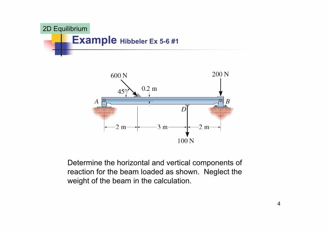
Example Hibbeler Ex 5-6 #1
2D Equilibrium
Determine the horizontal and vertical components of reaction for the beam loaded as shown. Neglect the weight of the beam in the calculation
4
weight of the beam in the calculation.

Example Hibbeler Ex 5-6 #2
2D Equilibrium
Find: , , y x yA B B
Equilibrium of
0 (600 N)cos 45 0x x
ADB
F B
424.26 N 424 N Ans
0 (100 N)(2 m) (600 N)sin45 (5 m)
(600 N) 45 (0 2 ) (7 ) 0
x
B
B
M
A
(600 N)cos 45 (0.2 m) (7 m) 0
319.50 319 N Ans
0 (600 N) i 45 (100
y
y
A
A
F A N) (200 N) 0B
5
0 (600 N)sin45 (100y yF A
N) (200 N) 0
404.76 N 405 N Ansy
y
B
B

2D Supports Summary #1
2D Equilibrium
6
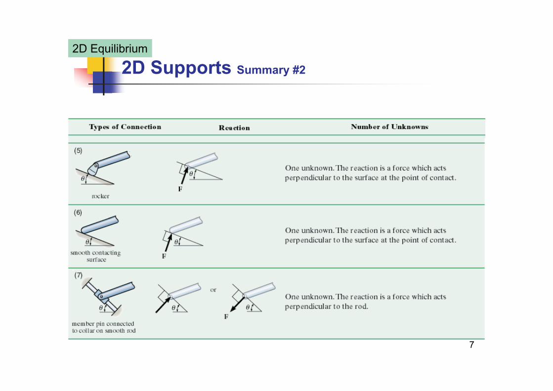
2D Supports Summary #2
2D Equilibrium
7

2D Supports Summary #3
2D Equilibrium
8
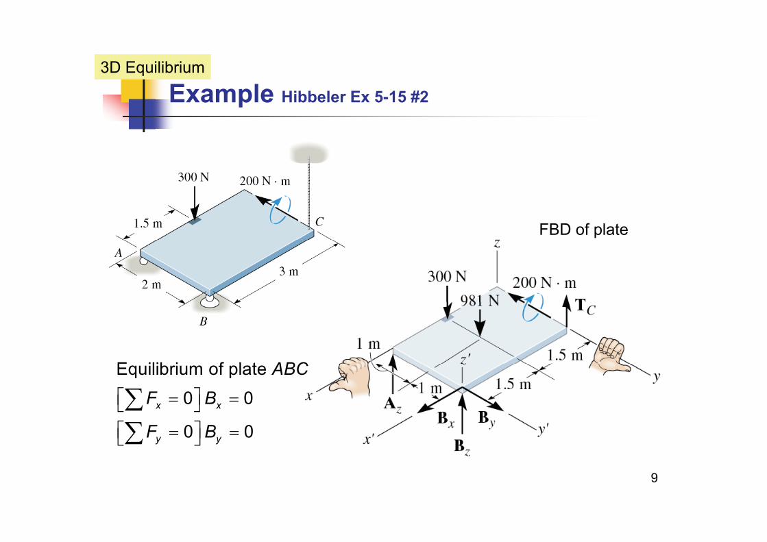
Example Hibbeler Ex 5-15 #2
3D Equilibrium
FBD of plate
E ilib i f l t ABC
Equilibrium of plate
0 0
0 0x x
ABC
F B
F B
9
0 0y yF B

Example Hibbeler Ex 5-15 #3
3D Equilibrium
Equilibrium of plate
0 (300 N) (980 7 N) 0 (1)
ABC
F A B T
0 (300 N) (980.7 N) 0 (1)
0 (2 m) (980.7 N)(1 m) (2 m) 0 (2)z z z C
x C z
F A B T
M T B
0 (300 N)(1.5 m) (980.7 N)(1.5 m) (3 m)
(3 m) (200 N m) 0 (3)y z
z
M B
A
Solve (1), (2) & (3)
790.35 N, 216.67 N, z zA B 707.02 N
790 N 707 N
CT
A T
10
790 N, 707 N, 0, 217 N Ans
z C
x y z
A TB B B

3D Supports Summary #1
3D Equilibrium
11
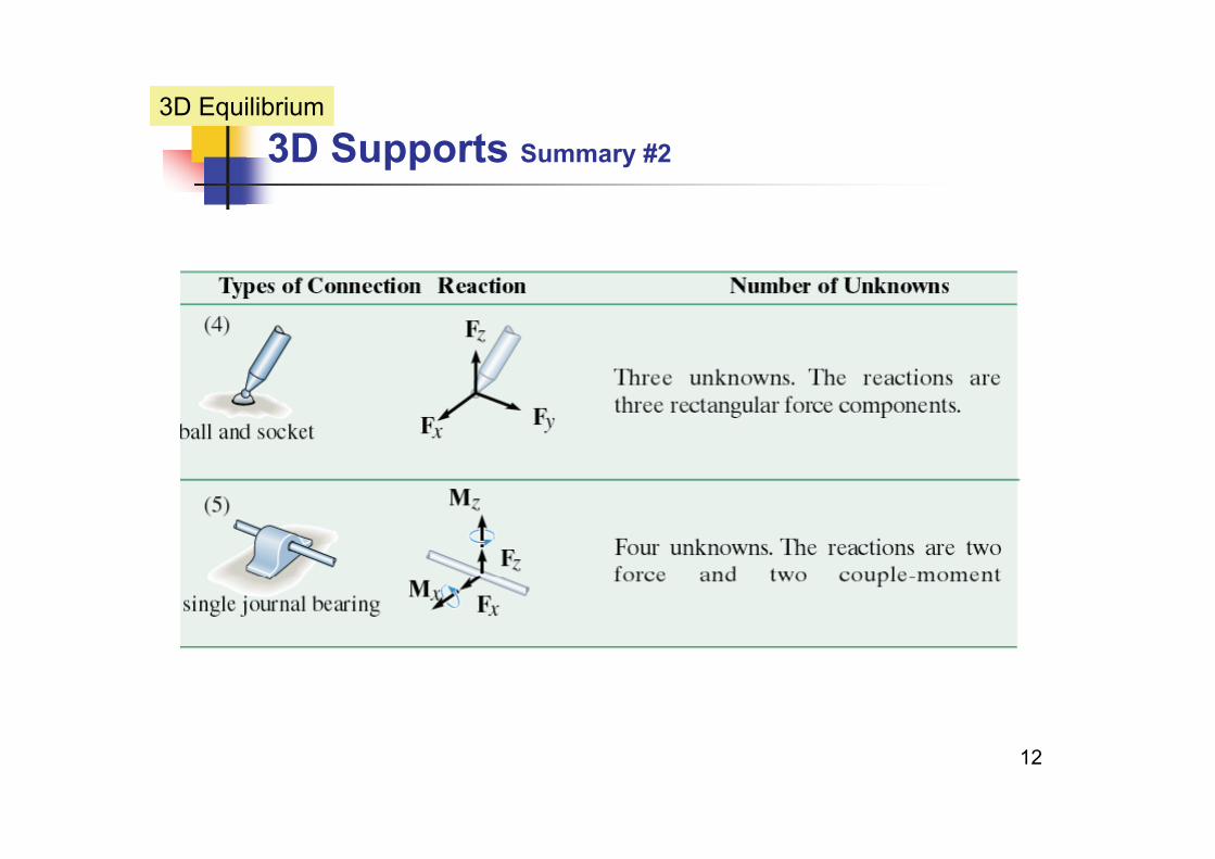
3D Supports Summary #2
3D Equilibrium
12

3D Supports Summary #3
3D Equilibrium
13

3D Supports Summary #4
3D Equilibrium
14Comparison with 2D supports

Example Structure
Disassembling the structure
15
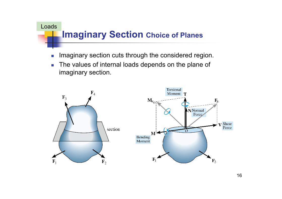
Imaginary Section Choice of PlanesLoads
Imaginary section cuts through the considered region. The values of internal loads depends on the plane of The values of internal loads depends on the plane of
imaginary section.
16

Stress Normal and Shear StressesLoads
17
avgNA
avgVA

Strain Normal and Shear StrainsLoads
2nt
avg
s ss L
18

Axially Loaded MembersAxial Load
A homogeneous and isentropic prismatic bar is subjected to axial load.
, , latPA L L
, , latA L L
19

Changes in Lengths Prismatic BarsAxial Load
A prismatic bars has straight longitudinal axis and constant cross gsection.
P , , P EA L
PLAE
20

Example Hibbeler 4-4 #1Axial Load
The bronze C86100 shaft is subjected to the axial loads shown. If the diameters of each segment are dAB = 0.75 in., dBC = 2 in., and dCD = 0.5 in., determine the displacement of end A with respect to end D.
3
21
315.0 10 ksiE
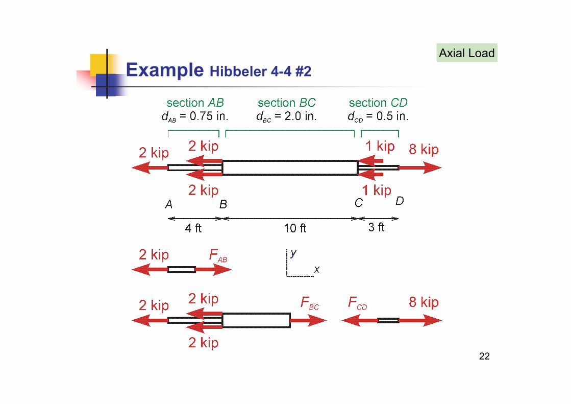
Example Hibbeler 4-4 #2Axial Load
22

Example Hibbeler 4-4 #3Axial Load
FBD of section A
0 2 kip 0
2 kip (T)x AB
AB
F F
F
FBD of section
0 3(2 kip) 0
AB
F F
0 3(2 kip) 0
6 kip (T)x BC
BC
F F
F
FBD of section
0 8 kip 0x CD
AD
F F
23
p
x CD
8 kip (T)CDF

Example Hibbeler 4-4 #4Axial Load
24

Example Hibbeler 4-4 #5Axial Load
(2.0 kip)(48 in.) 0 01448 iAB ABF L
2 3
(2.0 kip)(48 in.) 0.014487 in.(0.75 in.) (15.0 10 ksi)
4(6 0 ki )(120 i )
AB ABAB
AB
F LA E
F L
2 3
(6.0 kip)(120 in.) 0.015279 in.(2.0 in.) (15.0 10 ksi)
4
BC BCBC
BC
F LA E
2 3
(8.0 kip)(36 in.)
(0.5 in.) (15.0 10 ks4
CD CDCD
CD
F LA E
0.097785 in.i)
4
AD AB BC CD
25
0.127551 in. 0.158 in. Ans

Torsion Linearly Elastic Circular BarsTorsion
, max maxG Gr Gcc
26

Torsion FormulaTorsion
AT dM
TrJ
TLGJ
27

Polar Moment of InertiaTorsion
2 3
Solid shaft
(2 ) 2r r
J d d
2 3
0 0 (2 ) 2 J d d
4 4r d 2 32r dJ
2 2
1 1
2 3
Tubular shaft or circular tube
(2 ) 2 r r
r rJ d d
1 1r r
4 4 4 41 2 1 2( ) ( )J r r d d
28
1 2 1 2( ) ( )2 32

Example Gere 3.4-2 #1Torsion
A stepped shaft ABCD consisting of solid circular segments is subjected to three torques as shown. The material is steel with h d l f l ti it G 80 GPshear modulus of elasticity G = 80 GPa.
(a) Calculate the maximum shear stress τmax in the shaft.(b) Calculate the angle of twist φD (in degrees) at end D. (b) Ca cu ate t e a g e o t st φD ( deg ees) at e d
29

Example Gere 3.4-2 #2Torsion
FBD of shaft 0
3000 N mx
A
M
T
30
2000 N m 800 N m 05800 N mAT

Example Gere 3.4-2 #3Torsion
FBD of section in equilibriumA FBD of section in equilibrium
0 0 5800 N m
FBD of section in equilibriumx A AB AB
A
M T T T
B FBD of section in equilibrium
0 3000 N m 0 2800 N m
FBD of section in equilibriumx AB BC BC
B
M T T T
C
31
FBD of section in equilibrium
0 2000 N m 0x BC CD CD
C
M T T T 800 N m

Example Gere 3.4-2 #4Torsion
32

Example Gere 3.4-2 #5Torsion
4 3 4
2 16 32, maxTr Tr T TL TLJ GJr d G d
6
Section 16 16(5800 N m)( ) 57 694 10 PaAB
J GJr d G dAB
T
3 3
4 9 2 4
( ) 57.694 10 Pa(0.08 m)
32 32(5800 N m)(0.5 m) 0.0090146 rad(80 10 N/ ) (0 08 )
max ABAB
AB ABAB
dT L
G d
4 9 2 4(80 10 N/m ) (0.08 m)Section
1
ABABG d
BC 66 16(2800 N m)BCT
1( )max BC
63 3
6 16(2800 N m) 66.020 10 Pa(0.06 m)
32 32(2800 N m)(0.5 m) 0 013754 rad
BC
BC
BC BC
Td
T L
33
4 9 2 4 0.013754 rad
(80 10 N/m ) (0.06 m)BCBCG d
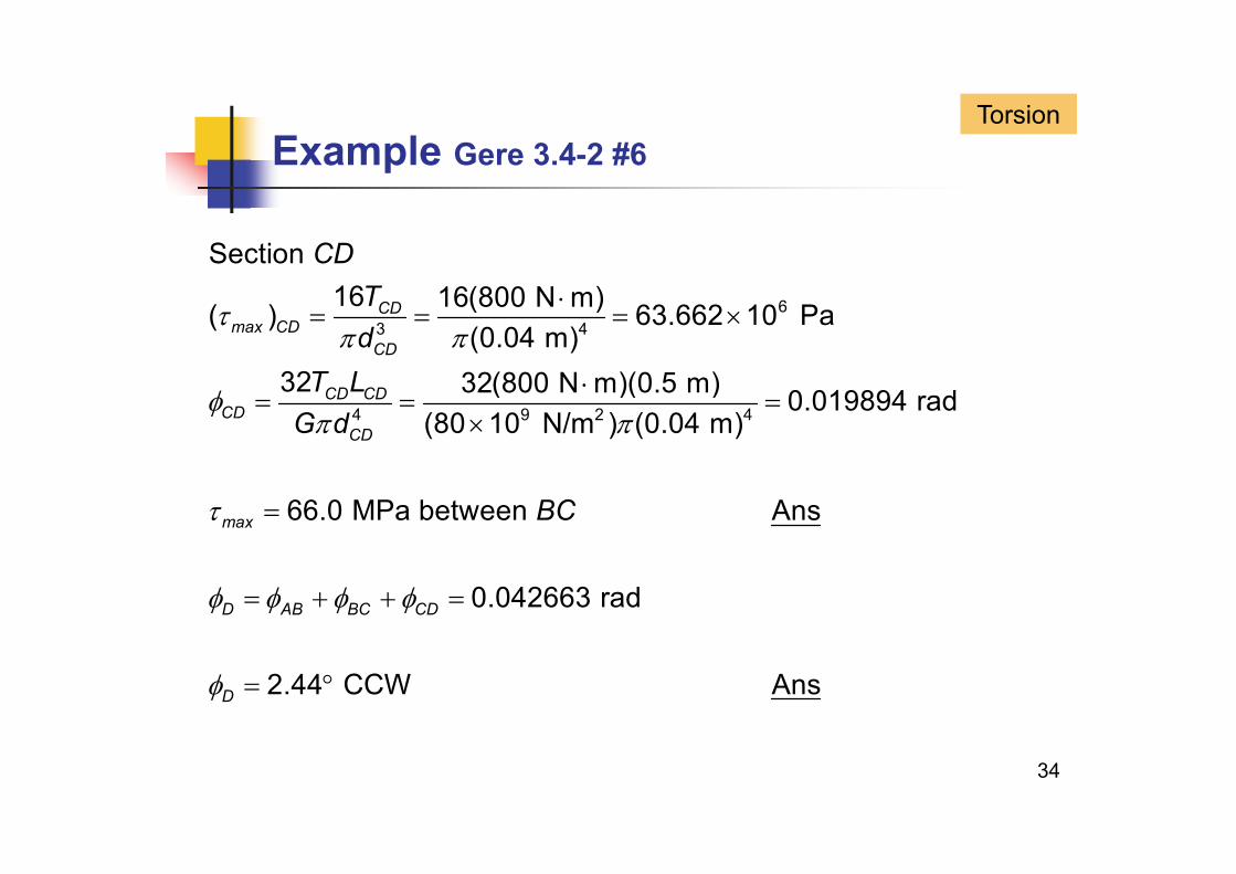
Example Gere 3.4-2 #6Torsion
Section 16 16(800 N )
CDT
63 4
16 16(800 N m)( ) 63.662 10 Pa(0.04 m)
32 32(800 N m)(0 5 m)
CDmax CD
CD
Td
T L
4 9 2 4
32 32(800 N m)(0.5 m) 0.019894 rad(80 10 N/m ) (0.04 m)
CD CDCD
CD
T LG d
66.0 MPa between Ans
0 042663 d
max BC
0.042663 rad
2 44
D AB BC CD
CCW Ans
34
2.44D CCW Ans

Flexure FormulaBending
The neutral axis NA does not change length.
0 NA passes through the centroid.
Load & stress relationshipx
z
F
M M
MyI
35

C & I: Centroid and Moment of InertiaBending
3 3
Area ( , )
(0 0)
x yx y I I
bh hbbh (0,0)12 12
bh
2 4 4
(0,0)4 64 64D D D
21cx xI I Ad
36

Shear Formula DerivationBending
0F 0xF
VQIt
Q y A
Q y A
37
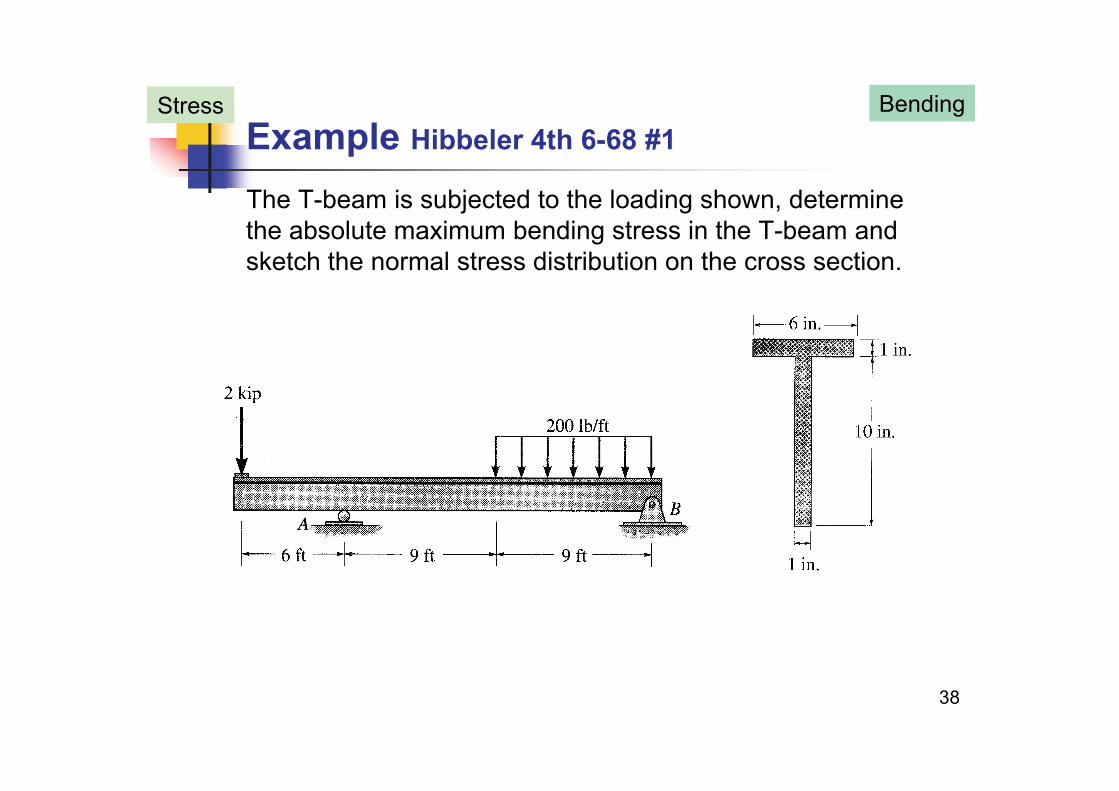
Example Hibbeler 4th 6-68 #1Stress Bending
The T-beam is subjected to the loading shown, determine the absolute maximum bending stress in the T-beam and sketch the normal stress distribution on the cross sectionsketch the normal stress distribution on the cross section.
38

Example Hibbeler 4th 6-68 #2Stress Bending
FBD of whole T-beam
0 0BF H 0 0
0 2 6 1.8 13.5 18 0
12 3 /18 0 68333 kip
x B
A B
F H
M R
R
12.3 /18 0.68333 kip
0 2 1.8 0
56 1/18 3 1167 kip
B
y A B
R
F R R
R
56.1/18 3.1167 kipAR
39

Example Hibbeler 4th 6-68 #3Stress Bending
FBD 1: 0 6 ft
0 2 0
x
F V
0 2 0
2 kip
0 2 0
yF V
V
M x M
0 2 0
2 kip ftOM x M
M x
FBD 2: 6 ft 15 ft
0 2 3.1167 0y
x
F V
1.1167 kip
0 3.1167( 6) 2 0
y
O
V
M x x M
40
1.1167 18.700 kip ftM x

Example Hibbeler 4th 6-68 #4Bending
FBD 3 0 9 ft ( 24 ft)
1 1
1
FBD 3: 0 9 ft ( 24 ft)
0 0.2 0.68333 0
0 2 0 68333 0 2 4 1167 kipy
x x x
F V x
V
1
1 1 1
2
0.2 0.68333 0.2 4.1167 kip
0 0.2 ( / 2) 0.68333 0
0 1 0 6833F
V x x
M M x x x
M
41
21 12
0.1 0.6833
0.1 4.1167 41.200 kip ft
x
M
M x
x x

Example: Hibbeler 4th 6-68 #5Bending
42

Example Hibbeler 4th 6-68 #6Bending
Consider T-beam cross sectionNA locates on centroid ( , ).C y z
1 1 2 2
By symmetry about axis, 0
i i
y zy A y A y A
1 1 2 2
1 2
(10 0.5) (6 1) 5 (1 10)
i i
i
y A y A y Ay
A A A
y
(6 1) (1 10)7.0625 in.y
y
43

Example Hibbeler 4th 6-68 #7Bending
Consider T-beam cross sectionNA locates on centroid ( )C y zNA locates on centroid ( , ).
Find about neutral axis
C y z
I2 2
1 1 2 2
3 2
( ) ( )
1 6(1) 6(10.5 7.0625)
y yI I
I
Ad I Ad
3 2
6(1) 6(10.5 7.0625)121 1(10) 10(7.0625 5)
12
I
I
44
4197.27 in.I

Example Hibbeler 4th 6-68 #8Bending
Abs max bending moment12 kip ft at 6 ftmaxM x
, at 6 ftMy xI
( 12 12) 3.9375 2.8742 ksi
197.27( 12 12) ( 7 0625)
top
45
( 12 12) ( 7.0625) 5.1554 ksi197.27bottom

Example: Hibbeler 4th 6-68 #9
46Abs max bending stress 5.16 ksi (C) Ansmax
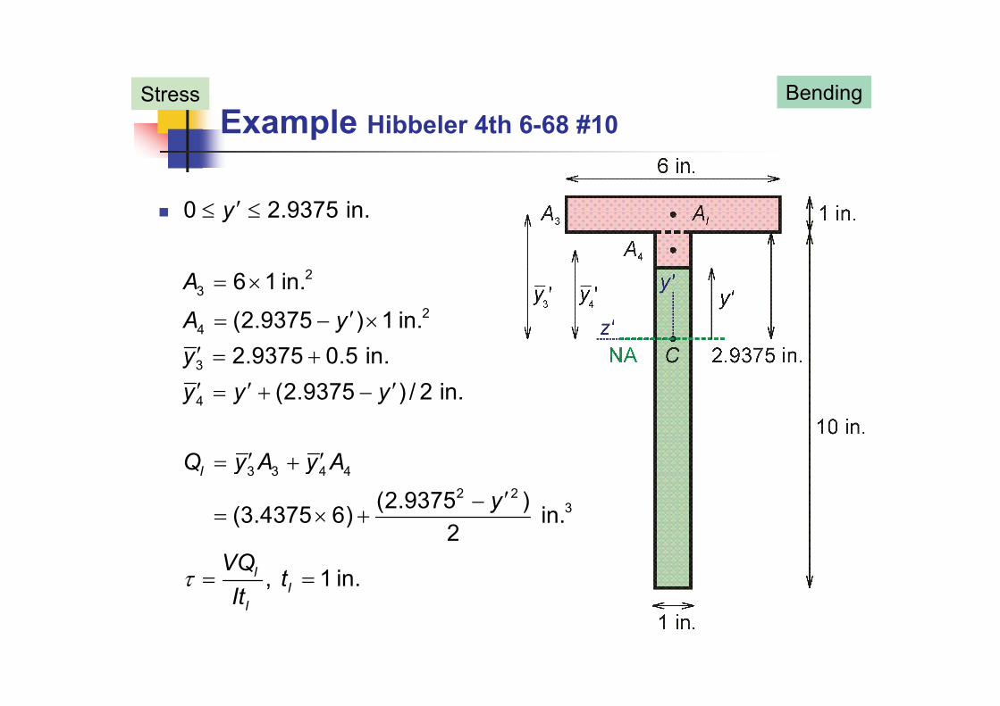
Example Hibbeler 4th 6-68 #10Stress Bending
0 2.9375 in. y
23
2
6 1 in.
(2 9375 ) 1 i
A
A
24
3
(2.9375 ) 1 in. 2.9375 0.5 in.
(2 9375 ) / 2 in
A yyy y y
4
3 3 4 4
(2.9375 ) / 2 in.
I
y y y
Q y A y A
3 3 4 42 2
3(2.9375 ) (3.4375 6) in.2
I
I
y y
y
VQ
Q
47
, 1 in.II
I
VQt
It

Example Hibbeler 4th 6-68 #11Stress Bending
7.0625 in. 0y
2 (7.0625 ) 1 in.II
y
A y
0.5(7.0625 ) in.IIy y y
Q A
2 2 3
1 (7.0625 ) in.2II
II II IIQ y A
yQ
2
, 1 in.IIII
VQt
48
, 1 in.IIII
tIt

Example Hibbeler 4th 6-68 #12Stress Bending
Between 0 6 ftx
Abs max is ve upward stress direction V
V Q V Q
0 2.9375 in., max max I
I
V Q V Qy
It ItV QV Q
7.0625 in. 0, max II
II
max V Qy
ItV Q
It
max
at NA 0
2 0.5( 7.
max
max II
yV Q
2 20625 0 ) 0.253 ksi Ans
49
maxIIIt
0 53 s s197.27 1

Example Hibbeler 4th 6-68 #13Stress Bending
2 9375 in 3 9375 iny
1
2
2.9375 in. 3.9375 in.
6 (3.9375 ) in.III
y
A y
( ) (3.9375 ) / 2 in.
III
III
yy y y
2 2 3
3(3.9375 ) in.III III III
III
Q y A
yQ
, t 6 in.IIIIII
III
VQIt
50
IIIIt

Example Hibbeler 4th 6-68 #14Stress Bending
51

Integration Slopes & DeflectionsBending
Successive integrationsFind constants of integration through
Find constants of integration through Boundary conditions Find constants of integration through
Continuity condition Symmetry condition
2d v M2 EIdx
52

Example Hibbeler 12-6 #1Bending
Determine the equations of the elastic curve for the beam and specify the beam’s maximum deflection. EI is constant.
53

Example Hibbeler 12-6 #2Bending
FBD of whole beam
0 0
3 30 ( ) 02 2
x A
A B B
F H
L PM R L P R
( )2 2
0 02
A B B
y A B APF R R P R
54

Example Hibbeler 12-6 #3Bending
Section 1: 0 x L
0 02 2yP PF V V
Px
0 02A
PxM M Vx M
55

Example Hibbeler 12-6 #4Bending
3Section 2: 2LL x
30 02 2
3 3
yP PF V V P
P
56
3 30 02 2APM L Vx M M Px PL

Example Hibbeler 12-6 #5Bending
57

Example Hibbeler 12-6 #6Bending
22
Section 1: 0 x Ld v P dv P
212
31 2
(1)2 4
(2)
d v P dv PEI M x EI x Cdxdx
PEIv x C x C
1 2
22
( )12
At , 0, 0 with (2) 0A x v C
PL
1
2 2 2
At , , 0 with (2) 12
At
PLB x L v C
dv PL PL PLB x L v EIv
58
At , , 4 12 6B BB x L v EIv
dx

Example Hibbeler 12-6 #7Bending
3Section 2: 2LL x
22
32
23 3 (3)2 2 2
d v dv PEI M Px PL EI x PLx Cdxdx
3 23 4
2 2
2 2 23 x (4)
6 45
dxdxPEIv x PLx C C
d PL PL
2 2
3
3
5At , , with (3) 6 6
At 0 ith (4)
dv PL PLB x L Cdx EI
PLB L C
59
4At , , 0 with (4) 4
PLB x L v C
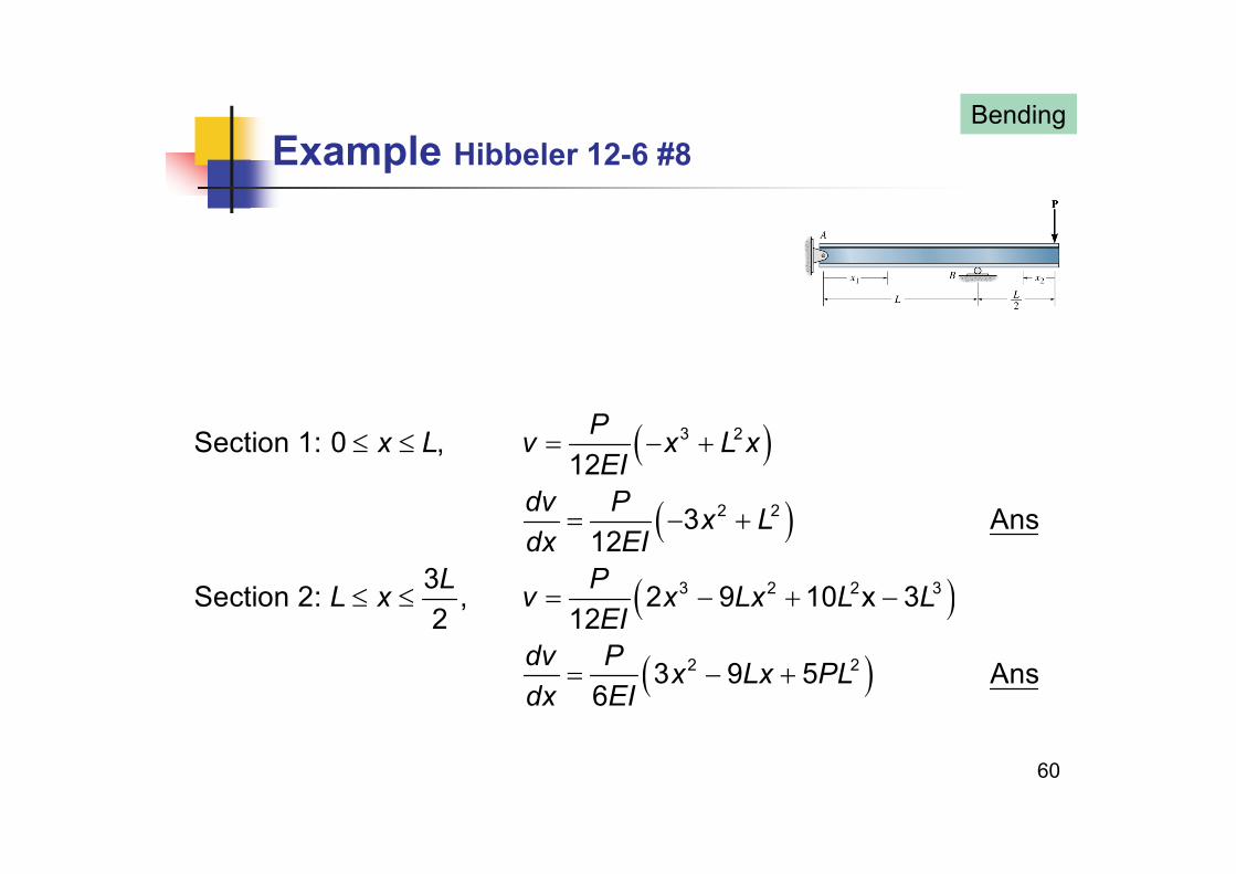
Example Hibbeler 12-6 #8Bending
3 2Section 1: 0 ,12
Px L v x L xEI
2 2
3 2 2 3
3 Ans12
3S ti 2 2 9 10 3
dv P x Ldx EI
L PL L L L
3 2 2 3
2 2
3Section 2: , 2 9 10 x 32 12
3 9 5 Ans6
L PL x v x Lx L LEI
dv P x Lx PLd EI
60
6dx EI

Example Hibbeler 12-6 #9Bending
61
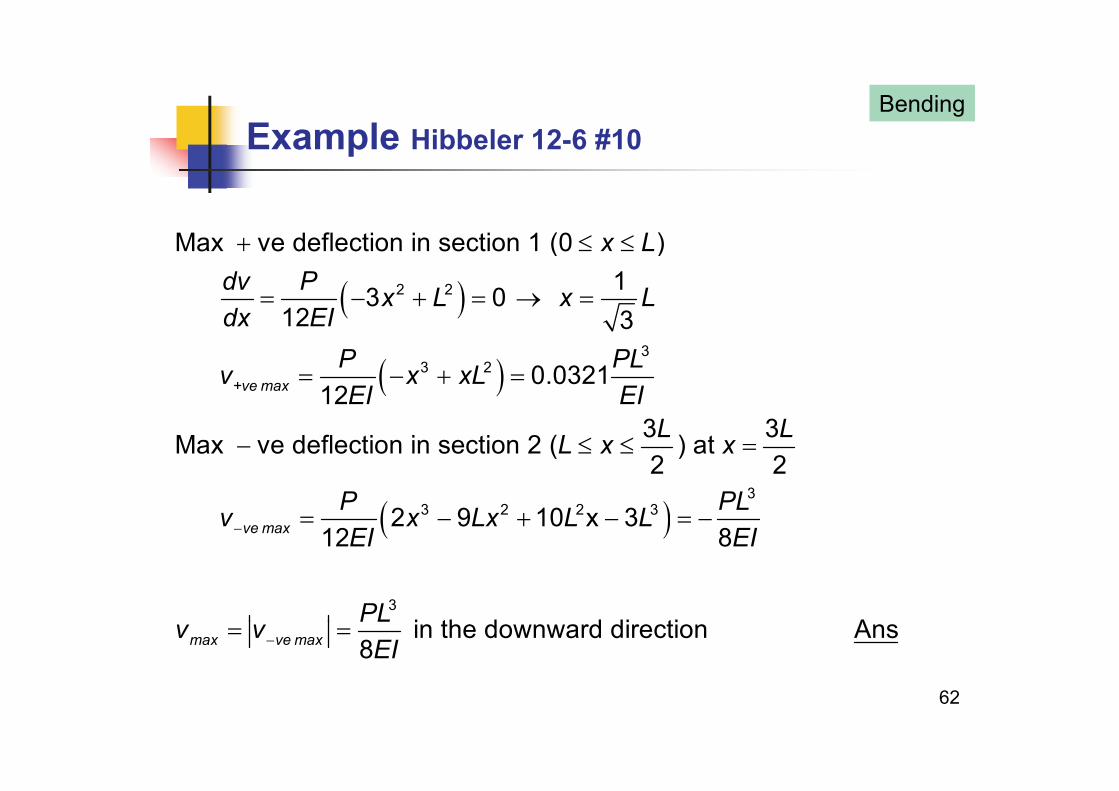
Example Hibbeler 12-6 #10Bending
Max ve deflection in section 1 (0 )x L
2 2
3
13 012 3
dv P x L x Ldx EI
P PL
3
3 2 0.032112
3 3Max ve deflection in section 2 ( ) at
+ve maxP PLv x xLEI EI
L LL x x
3
3 2 2 3
Max ve deflection in section 2 ( ) at 2 2
2 9 10 x 312 8ve max
L x x
P PLv x Lx L LEI EI
12 8ve max EI EI
3
i th d d di ti APL
62
max ve mav v in the downward direction Ans8xPLEI

Statically Indeterminate Members The reactions of members cannot be determined by
equilibrium equations alone.
The degree of static indeterminacy is the number of reactions in excess of the number of equilibrium equations.
63
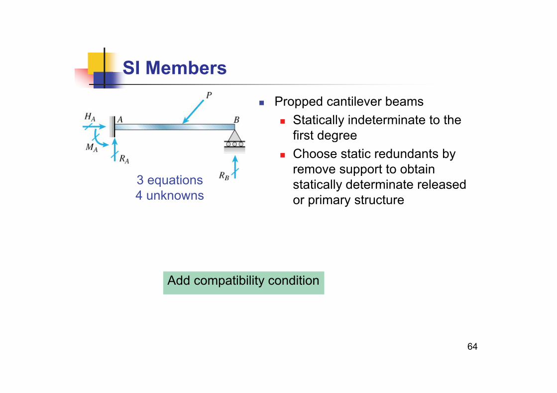
SI Members Propped cantilever beams
Statically indeterminate to the first degree
Choose static redundants by remove support to obtain ppstatically determinate released or primary structure
3 equations4 unknowns
Add compatibility condition
64

Pressure Vessels Sphere
Consider half section
220 (2 ) 0
2x mprF r t p rr t
pr
65
2/ 2
m
m
r tr r t r
2p
t

Pressure Vessels Closed Cylinder
Consider half section
0 (2 ) 2 0F bt pbr 10 (2 ) 2 0
Consider cross sectional section
xF bt pbr
22
Consider cross sectional section
0 (2 ) 0z mF r t p r
pr
pr
1 circumferencial or hoop stress
1 t 2 2tσ2
66
1
2
plongitudinal or axial stress