lecture no: 1 - genrica.com
TRANSCRIPT

Software Design – CS 711 VU
© Copyright Virtual University of Pakistan 1
LECTURE NO: 1
Objective: In this lecture we will discuss “software crisis” in detail with reason behind this crisis. It will be
followed by discussion on the classic model with reference to water fall model and V model, what
are the drawbacks in this model and then need for an Agile process model
History of software crisis: Software crisis was a term used in the early days of computing science. The term was used to
describe the impact of rapid increases in computer power and the complexity of the problems
which could be tackled. In essence, it refers to the difficulty of writing correct, understandable,
and verifiable computer programs. The term "software crisis" was coined by F. L. Bauer at the
first NATO Software Engineering Conference in 1968 at Garmisch, Germany
Software CHAOS Report Standish Group Study In 1986, Alfred Spector, president of Transarc Corporation, co-authored a paper comparing
bridge building to software development. The premise: Bridges are normally built on-time, on
budget, and do not fall down. On the other hand, software never comes in on-time or on-budget.
In addition, it always breaks down. (Nevertheless, bridge building did not always have such a
stellar record. Many bridge building projects overshot their estimates, time frames, and some even
fell down.).
One of the biggest reasons bridges come in on-time, on-budget and do not fall down is because
of the extreme detail of design. The design is frozen and the contractor has little flexibility in
changing the specifications. However, in today's fast moving business environment, a frozen
design does not accommodate changes in the business practices. Therefore a more flexible
model must be used. This could be and has been used as a rationale for development failure.
But there is another difference between software failures and bridge failures, beside 3,000
years of experience. When a bridge falls down, it is investigated and a report is written on the
cause of the failure. This is not so in the computer industry where failures are covered up,
ignored, and/or rationalized. As a result, we keep making the same mistakes over and over
again.

Software Design – CS 711 VU
© Copyright Virtual University of Pakistan 2
FAILURE RECORD In the United States, we spend more than $250 billion each year on IT application development
of approximately 175,000 projects. The average cost of a development project for a large
company is $2,322,000; for a medium company, it is $1,331,000; and for a small company, it is
$434,000. A great many of these projects will fail. Software development projects are in chaos,
and we can no longer imitate the three monkeys -- hear no failures, see no failures, speak no
failures.
The Standish Group research shows a staggering 31.1% of projects will be cancelled before
they ever get completed. Further results indicate 52.7% of projects will cost 189% of their
original estimates. The cost of these failures and overruns are just the tip of the proverbial
iceberg. The lost opportunity costs are not measurable, but could easily be in the trillions of
dollars. One just has to look to the City of Denver to realize the extent of this problem. The
failure to produce reliable software to handle baggage at the new Denver airport is costing the
city $1.1 million per day. Based on this research, The Standish Group estimates that in 1995
American companies and government agencies will spend $81 billion for cancelled software
projects. These same organizations will pay an additional $59 billion for software projects that
will be completed, but will exceed their original time estimates. Risk is always a factor when
pushing the technology envelope, but many of these projects were as ordinary as a drivers license
database, a new accounting package, or an order entry system.
On the success side, the average is only 16.2% for software projects that are completed on time
and on-budget. In the larger companies, the news is even worse: only 9% of their projects
come in on-time and on-budget. And, even when these projects are completed, many are no
more than a mere shadow of their original specification requirements. Projects completed by the
largest American companies have only approximately 42% of the originally-proposed features
and functions. Smaller companies do much better. A total of 78.4% of their software projects will
get deployed with at least 74.2% of their original features and functions.
This data may seem disheartening, and in fact, 48% of the IT executives in our research sample
feel that there are more failures currently than just five years ago. The good news is that over
50% feel there are fewer or the same number of failures today than there were five and ten years
ago.

Software Design – CS 711 VU
© Copyright Virtual University of Pakistan 3
Reasons for Failure:
i. Unclear, unstable, misunderstood and missing requirements
ii. To late integration of results of working and components, thus to late recognition of risks
and errors
iii. Fast changing technologies
iv. Missing Quality Management
v. Overvaluation of documents
vi. No model-based process
Examples of Software Failures:
First Known Software Bug: Buggy Computer Club, in 1945 engineers found a moth in Panel F, Relay #70 of the Harvard
Mark II system. The computer was running a test of its multiplier and adder when the engineers
noticed something was wrong. The moth was trapped, removed and taped into the computer's
logbook with the words: "first actual case of a software bug being found."
i. NASA: Mariner Failure in 1962 A bug in the flight software for the Mariner 1 causes the rocket to divert from its intended path on
launch. Mission control destroys the rocket over the Atlantic Ocean. The investigation into the
accident discovers that a formula written on paper in pencil was improperly transcribed into
computer code, causing the computer to miscalculate the rocket's trajectory.
ii. Korean Airliner Crash The Korean Airlines KAL 801 accident in Guam killed 225 out of 254 aboard. A software design
problem was discovered in barometric altimetry in Ground Proximity Warning System (GPWS)
iii. Customer Tracking System

Software Design – CS 711 VU
© Copyright Virtual University of Pakistan 4
In 1996 a San Francisco bank was poised to roll out an application for tracking customer calls.
Reports provided by the new system would be going directly to the president of the bank and
board of directors. An initial product demo seemed sluggish, but telephone banking division
managers were assured by the designers that all was well. But the system crashed constantly,
could not support multiple users at once and did not meet the bank’s security requirements. After
three months the project was killed; resulting in a loss of approximately $200,000 in staff time
and consulting fees.
Problems:
i. The bank failed to check the quality of its contractors
ii. Complicated reporting structure with no clear chain of command
iii. Nobody “owned” the software
iv. Pay Roll System Failure:
The night before the launch of a new payroll system in a major US health-care organization,
project managers hit problems. During a sample run, the off-the-shelf package began producing
cheques for negative amounts, for sums larger than the top executive’s annual take-home pay, etc.
Payroll was delivered on time for most employees but the incident damaged the relationship
between information systems and the payroll and finance departments, and the programming
manager resigned in disgrace.
Problems:
i. The new system had not been tested under realistic conditions
ii. Differences between old and new systems had not been explained (so $8.0 per hour was
entered as $800 per hour)
iii. “A lack of clear leadership was a problem from the beginning”
Critical Failure Factors: Critical reason for failures as discussed in some of the major examples above are as follow:
i. Organization: hostile culture, poor reporting structures
ii. Management: over-commitment, political pressures
iii. Conduct of the project:
a. Initiation phase: technology focused, lure of leading edge, complexity
underestimated

Software Design – CS 711 VU
© Copyright Virtual University of Pakistan 5
b. Analysis and design phase: poor consultation, design by committee, technical fix
for management problem, poor procurement
c. Development phase: Staff turnover, poor competency, poor communication (e.g.
split sites)
d. Implementation phase: receding deadlines, inadequate testing, inadequate user
training.
Software Process – An Overview
“Software Processes model models desired phases or activities in the project”
Water Fall Model: The waterfall model is a model for software development (a process for the creation of software),
which develop regularly flowing downwards (like a waterfall). The development runs through a
number of phases, namely: definition study / analysis, basic design, technical design / detailed
design, construction, testing, integration, management and maintenance. Previously, a large
software development, especially large cluttered knitting. With the advent of this new method, the
computer companies hoped to clarify in their projects. The waterfall model is derived from the
traditional way of working in large construction projects in construction. The purpose of this way
of working is that divides the project into phases. You start with phase 1 and phase 2 to begin no
earlier than when you have completed Phase 1. And when you’re in a phase of an error you must
do to correct back to that stage and the subsequent steps again.
History of Water Fall Model:
On the origin of the term “waterfall” is often said that Winston Royce introduced it in 1970, but
Royce saw them more in the repeated approach to software development and even used the term
“waterfall”. Royce described the waterfall model as a method he ventured even an invitation to
failure occurred. In 1970 Royce was that the waterfall model should be seen as the first draft, he
felt that the method has flaws. He brought a document which examined how the initial concept
to a recurrent method could be developed; this new model in each phase was between a
feedback to the previous stage, as we now see in many current methods. Royce was just
annoying for the initial focus method, the criticism he had on this method was largely
ignored. Despite Royce’s intentions to the waterfall model into a repeat method (iterative
model), the use of this method is still very popular, but opponents of the waterfall model see it
as a naive and inappropriate method for use in the real world “.

Software Design – CS 711 VU
© Copyright Virtual University of Pakistan 6
Phases of Water Fall Model
Requirement Analysis & Definition:
All requirements of the system which has to be developed are collected in this step. Like in other
process models requirements are split up in functional requirements and constraints which the
system has to fulfill. Requirements have to be collected by analyzing the needs of the end user(s)
and checking them for validity and the possibility to implement them. The aim is to generate a
Requirements Specification Document which is used as an input for the next phase of the model.
System Design:
The system has to be properly designed before any implementation is started. This involves an
architectural design which defines and describes the main blocks and components of the system,
their interfaces and interactions. By this the needed hardware is defined and the software is split
up in its components. E.g. this involves the definition or selection of a computer platform, an
operating system, other peripheral hardware, etc. The software components have to be defined to
meet the end user requirements and to meet the need of possible scalability of the system. The
aim of this phase is to generate a System Architecture Document this serves as an input for the
software design phase of the development, but also as an input for hardware design or selection
activities. Usually in this phase various documents are generated, one for each discipline, so that
the software usually will receive a software architecture document.

Software Design – CS 711 VU
© Copyright Virtual University of Pakistan 7
Software Design:
Based on the system architecture which defines the main software blocks the software design will
break them further down into code modules. The interfaces and interactions of the modules are
described, as well as their functional contents. All necessary system states like startup, shutdown,
error conditions and diagnostic modes have to be considered and the activity and behavior of the
software has to be defined. The output of this phase is a Software Design Document which is the
base of the following implementation work.
Coding:
Based on the software design document the work is aiming to set up the defined modules or units
and actual coding is started. The system is first developed in smaller portions called units. They
are able to stand alone from an functional aspect and are integrated later on to form the complete
software package.
Software Integration & Verification:
Each unit is developed independently and can be tested for its functionality. This is the so called
Unit Testing. It simply verifies if the modules or units to check if they meet their specifications.
This involves functional tests at the interfaces of the modules, but also more detailed tests which
consider the inner structure of the software modules. During integration the units which are
developed and tested for their functionalities are brought together. The modules are integrated
into a complete system and tested to check if all modules cooperate as expected.
System Verification:
After successfully integration including the related tests the complete system has to be tested
against its initial requirements. This will include the original hardware and environment, whereas
the previous integration and testing phase may still be performed in a different environment or on
a test bench.
Operation & Maintenance:
The system is handed over to the customer and will be used the first time by him. Naturally the
customer will check if his requirements were implemented as expected but he will also validate if
the correct requirements have been set up in the beginning. In case there are changes necessary it

Software Design – CS 711 VU
© Copyright Virtual University of Pakistan 8
has to be fixed to make the system usable or to make it comply to the customer wishes. In most of
the "Waterfall Model" descriptions this phase is extended to a never ending phase of
“Operations & Maintenance". All the problems which did not arise during the previous phases
will be solved in this last phase.
Advantages
If in the beginning of the project failures are detected, it takes less effort (and therefore time and
money) for this error. In the waterfall model phases are properly sealed first before proceeding
to the next stage. It is believed that the phases are correct before proceeding to the next phase. In
the waterfall model laid down the emphasis on documentation. In the newer software
development methodologies makes it less documentation. This means that when new people
come in the project, and people leave it is difficult to transfer knowledge. This disadvantage is
not the traditional waterfall model. It is a straightforward method. The way of working ensures
that there are specific phases. This tells you what stage it is. One can use this method of
milestones. Milestones can be used to monitor the progress of the project to estimate. The
waterfall model is well known. Many people have experienced, so there might be easy to
work. When frequent portions of the software product to be delivered this gives the customer
confidence, but also the software development team.
Disadvantages There are some disadvantages of this way to develop software. Many software projects are
dependent on external factors. The client is a very important external factor. Often the
requirements over the course of the project change, because the client wants something
different. It is a disadvantage that the waterfall model assumes that the requirements will not
change during the project. When a requirement changes in the construction phase, a substantial
number of phases made again. It is very difficult to time and cost estimate. The phases are very
large, it is therefore very difficult to estimate how much each step cost. In a number of new
methods are almost all aspects of a software development process included. One can think of
planning techniques, project management methods and how the project should be organized.
For example: the designers and builders. They all have a different view of the project as
designers look at the project differently than the builder and conversely, the builders often look
different from the design of the designers look than the designers themselves.
Frequently, the design will be adjusted again. Here is the waterfall model is not made for
that. Within the project the team members often specialized. One team member will be only the

Software Design – CS 711 VU
© Copyright Virtual University of Pakistan 9
first phase involved the design, while the only builders in construction helping to build the
project. This can lead to waste of different sources. The main source is the time.
An example: Assume the software designers are working on perfecting the design. The programmers are in
principle already started building, but because they work with the waterfall model, they should
wait until the first phase is complete. This is a typical example of wasted time. Testing is done
only in one of the last phases of the project. In other software development methods will be
tested once a certain part and finished product is at last an integration test. Due to so much
emphasis on documentation, the waterfall model is not efficient for smaller projects. There’s too
much effort to the project itself around in terms of documentation.

Software Design – CS 711 VU
© Copyright Virtual University of Pakistan 10
V-Model – An Extension of Water Fall Model: Keeping in view of the disadvantages of Water Fall model, a refined version of Water Fall
model is developed which is known as “V-Model". If we look at it closely the individual steps
(in the diagram below) of the process are almost the same as in the waterfall model.
Therefore we will not describe the individual steps again, because the description of the
waterfall steps may substitute this. However, there is on big difference. Instead of going
down the waterfall in a linear way the process steps are bent upwards at the coding phase,
to form the typical V shape. The reason for this is that for each of the design phases it was
found that there is a counterpart in the testing phases which correlate to each other.
The time in which the V-model evolved was also the time in which software testing techniques
were defined and various kinds of testing were clearly separated from each other. This new
emphasis on software testing (of course along with improvements and new techniques in
requirements engineering and design) led to the evolution of the waterfall model into the V-
model. The tests are derived directly from their design or requirements counterparts. This made it
possible to verify each of the design steps individually due to this correlation.
Another idea evolved which was the traceability down the left side of the V. This means that
the requirements have to be traced into the design of the system, thus verifying that they are
implemented completely and correctly. Another feature can be observed when you compare the
waterfall model to the V-model. The "Operation & Maintenance" phase was replaced in later

Software Design – CS 711 VU
© Copyright Virtual University of Pakistan 11
versions of the V-model with the validation of requirements. This means that not only the correct
implementation of requirements has to be checked but also if the requirements are correct. In case
there is the need of an update of the requirements and subsequently the design and coding, etc.
there are two options. Either this has to be treated like in the waterfall model in a never ending
maintenance phase, or in going over to another V-cycle. The earlier versions of V-models used
the first option. For later versions a series of subsequent V-cycles was defined, as shown below:
This idea also correlated with the established sample phases for products as it is present in many
industries. One of the cascaded V-cycles became the V-cycle of a sample phase. In addition to
this the V-cycles were tailored. This means that in earlier sample phases not all the intermediate
work products and process step were established in their full beauty but it was simply reduced to
what makes sense. By these measures the V-model became a usable process model. It does not
consider every detail and possibility but evaluated over a multitude of projects in various
industries it proved its usability.

Software Design – CS 711 VU
© Copyright Virtual University of Pakistan 12
LECTURE NO: 2
Objective: This lecture will provide in depth knowledge of agile software processes and we will discuss
Extreme Programming – An agile software processes in detail.
Standish Report in 2006:
Studied 40,000 projects in 10 years
That's more than a 100-percent improvement from the success rate in 1995
The primary reason is the projects have gotten a lot smaller. Doing projects with iterative
processing as opposed to the waterfall method, which called for all project requirements
to be defined up front, is a major step forward
Agile Processes:
Slogan: “Change is the only constant”
Software development can be equated to any other engineering task. We believe software
development projects can be effectively managed by:
Understanding and writing specifications that define how the software will look and what it will
do. We need to perform in-depth analysis and design work before estimating development costs
We should ensuring software developers follow the specifications and then testing the software
after implementation to make sure it works as specified, and Delivering the finished result to the
user that is, if the specification is of sufficient detail, then the software will be written such that it
will satisfy the customer, will be within budget, and will be delivered on time.
One of the most important differences between the agile and waterfall approaches is that waterfall
features distinct phases with checkpoints and deliverables at each phase, while agile methods
have iterations rather than phases. The output of each iteration is a working code that can be used

Software Design – CS 711 VU
© Copyright Virtual University of Pakistan 13
to evaluate and respond to changing and evolving user requirements. Waterfall assumes that it is
possible to have perfect understanding of the requirements from the start. But in software
development, stakeholders often don’t know what they want and can’t articulate their
requirements. With waterfall, development rarely delivers what the customer wants even if it is
what the customer asked for.
Agile methodologies embrace iterations. Small teams work together with stakeholders to define
quick prototypes, proof of concepts (POC), or other visual means to describe the problem to be
solved. The team defines the requirements for the iteration, develops the code, and defines and
runs integrated test scripts, and the users verify the results. Verification occurs much earlier in the
development process than it would with waterfall, allowing stakeholders to fine-tune
requirements while they’re still relatively easy to change. In agile processes we use a term
“Release” which actually reflect a working and executable prototype of requirements which
have finalized for a particular iteration as per customer agreement.

Software Design – CS 711 VU
© Copyright Virtual University of Pakistan 14
Extreme Programming (XP) Extreme Programming was created by Kent Beck during his work on the Chrysler Comprehensive
Compensation System (C3) payroll project. Beck became the C3 project leader in March 1996
and began to refine the development method used in the project and wrote a book on the method
(in October 1999, Extreme Programming Explained was published). Chrysler cancelled the C3
project in February 2000, after the company was acquired by Daimler-Benz. Although extreme
programming itself is relatively new, many of its practices have been around for some time; the
methodology, after all, takes “best practices” to extreme levels. For example, the “practice of test-
first development, planning and writing tests before each micro-increment” was used as early as
NASA’s Project Mercury, in the early 1960s (Larman 2003). To shorten the total development
time, some formal test documents (such as for acceptance testing) have been developed in parallel
(or shortly before) the software is ready for testing. A NASA independent test group can write the
test procedures, based on formal requirements and logical limits, before the software has been
written and integrated with the hardware. In XP, this concept is taken to the extreme level by
writing automated tests (perhaps inside of software modules) which validate the operation of
even small sections of software coding, rather than only testing the larger features. Some other XP
practices, such as refactoring, modularity, bottom-up design, and incremental design were
described by Leo Brodie in his book published in 1984 Extreme Programming, or XP, is a
lightweight discipline of software development based on principles of simplicity, communication,
feedback, and courage. XP is designed for use with small teams who need to develop software
quickly in an environment of rapidly-changing requirements. XP can be summed up in twelve
practices as discussed below:
i. The Planning Process
The XP planning process allows the XP customer" to define the business value of desired
features, and uses cost estimates provided by the programmers, to choose what needs to be done
and what needs to be deferred. The effect of XP's planning process is that it is easy to steer the
project to success.
ii. Small Releases
XP teams put a simple system into production early, and update it frequently on a very short
cycle.

Software Design – CS 711 VU
© Copyright Virtual University of Pakistan 15
iii. Metaphor
XP teams use a common or system of names" and a common system description that guides
development and communication.
iv. Simple Design
A program built with XP should be the simplest program that meets the current requirements.
There is not much building for the future". Instead, the focus is on providing business value. Of
course it is necessary to ensure that you have a good design, and in XP this is brought about
through refactoring", discussed below.
v. Testing
XP teams focus on validation of the software at all times. Programmers develop software by
writing tests cases, then software that full-fills the requirements in the tests. Customers provide
acceptance tests that enable them to be certain that the features they need are provided.
vi. Refactoring
XP teams improve the design of the system throughout the entire development. This is done by
keeping the software clean: without duplication, with high communication, simple, yet complete.
vii. Pair Programming
XP programmers write all production code in pairs, two programmers working together at one
machine. Pair programming has been shown by many experiments to produce better software at
similar or lower cost than programmers working alone.
viii. Collective Ownership All the code belongs to all the programmers. This lets the team go at full speed, because when
something needs changing, it can be changed without delay.
ix. Continuous Integration
XP teams integrate and build the software system multiple times per day. This keeps all the
programmers on the same page, and enables very rapid progress. Perhaps surprisingly, integrating
more frequently tends to eliminate integration problems that plague teams who integrate less
often.

Software Design – CS 711 VU
© Copyright Virtual University of Pakistan 16
x. 40-hour Week
Tired programmers make more mistakes. XP teams do not work excessive overtime, keeping
themselves fresh, healthy, and effective.
xi. On-site Customer
An XP project is steered by a dedicated individual who is empowered to determine requirements,
set priorities, and answer questions as the programmers have them. The effect of being there is
that communication improves, with less hard-copy documentation - often one of the most
expensive parts of a software project.
xii. Coding Standard
For a team to work effectively in pairs, and to share ownership of all the code, all the
programmers need to write the code in the same way, with rules that make sure the code
communicates clearly.

Software Design – CS 711 VU
© Copyright Virtual University of Pakistan 17
XP Corners:
i. Communication Building software systems requires communicating system requirements to the developers of the
system. In formal software development methodologies, this task is accomplished through
documentation. Extreme programming techniques can be viewed as methods for rapidly building
and disseminating institutional knowledge among members of a development team. The goal is to
give all developers a shared view of the system which matches the view held by the users of the
system. To this end, extreme programming favors simple designs, common metaphors,
collaboration of users and programmers, frequent verbal communication, and feedback.
ii. Simplicity Extreme Programming encourages starting with the simplest solution. Extra functionality can then
be added later. The difference between this approach and more conventional system development
methods is the focus on designing and coding for the needs of today instead of those of tomorrow,
next week, or next month. Coding and designing for uncertain future requirements implies the
risk of spending resources on something that might not be needed. Related to the
"communication" value, simplicity in design and coding should improve the quality of
communication. A simple design with very simple code could be easily understood by most
programmers in the team.
iii. Feedback Within extreme programming, feedback relates to different dimensions of the system
development:
Feedback from the system: by writing unit tests,[5] or running periodic integration tests, the
programmers have direct feedback from the state of the system after implementing changes.
Feedback from the customer: The functional tests (aka acceptance tests) are written by the
customer and the testers. They will get concrete feedback about the current state of their system.
This review is planned once in every two or three weeks so the customer can easily steer the
development.
Feedback from the team: When customers come up with new requirements in the planning game
the team directly gives an estimation of the time that it will take to implement.
Feedback is closely related to communication and simplicity. Flaws in the system are easily
communicated by writing a unit test that proves a certain piece of code will break. The direct
feedback from the system tells programmers to recode this part. A customer is able to test the

Software Design – CS 711 VU
© Copyright Virtual University of Pakistan 18
system periodically according to the functional requirements, known as user stories. To
quote Kent Beck, "Optimism is an occupational hazard of programming. Feedback is
the treatment."
iv. Courage Several practices embody courage. One is the commandment to always design and code for today
and not for tomorrow. This is an effort to avoid getting bogged down in design and requiring a lot
of effort to implement anything else. Courage enables developers to feel comfortable
with refactoring their code when necessary.[5] This means reviewing the existing system and
modifying it so that future changes can be implemented more easily. Another example of courage
knows when to throw code away: courage to remove source code that is obsolete, no matter how
much effort was used to create that source code. Also, courage means persistence: A programmer
might be stuck on a complex problem for an entire day, then solve the problem quickly the next
day, if only they are persistent.

Software Design – CS 711 VU
© Copyright Virtual University of Pakistan 19
Principles of XP: The principles that form the basis of XP are based on the values just described and are intended to
foster decisions in a system development project. The principles are intended to be more concrete
than the values and more easily translated to guidance in a practical situation.
i. Feedback Extreme programming sees feedback as most useful if it is done rapidly and expresses that the
time between an action and its feedback is critical to learning and making changes. Unlike
traditional system development methods, contact with the customer occurs in more frequent
iterations. The customer has clear insight into the system that is being developed. He or she can
give feedback and steer the development as needed.
Unit tests also contribute to the rapid feedback principle. When writing code, the unit test
provides direct feedback as to how the system reacts to the changes one has made. If, for instance,
the changes affect a part of the system that is not in the scope of the programmer who made them,
that programmer will not notice the flaw. There is a large chance that this bug will appear when
the system is in production.
ii. Assuming simplicity This is about treating every problem as if its solution were "extremely simple". Traditional system
development methods say to plan for the future and to code for reusability. Extreme programming
rejects these ideas.
The advocates of extreme programming say that making big changes all at once does not work.
Extreme programming applies incremental changes: for example, a system might have small
releases every three weeks. When many little steps are made, the customer has more control over
the development process and the system that is being developed.
iii. Embracing change The principle of embracing change is about not working against changes but embracing them. For
instance, if at one of the iterative meetings it appears that the customer's requirements have
changed dramatically, programmers are to embrace this and plan the new requirements for the
next iteration.

Software Design – CS 711 VU
© Copyright Virtual University of Pakistan 20

Software Design – CS 711 VU
© Copyright Virtual University of Pakistan 21
Extreme Programming Project From practical view point, the following steps are performed as shown in below:
i. User Stories User stories serve the same purpose as use cases but are not the same. They are used to create
time estimates for the release planning meeting. They are also used instead of a large
requirements document. User Stories are written by the customers as things that the system needs
to do for them. They are similar to usage scenarios, except that they are not limited to describing a
user interface. They are in the format of about three sentences of text written by the customer in
the customer’s terminology without techno-syntax.
User stories also drive the creation of the acceptance tests. One or more automated acceptance
tests must be created to verify the user story has been correctly implemented. One of the biggest
misunderstandings with user stories is how they differ from traditional requirements
specifications. The biggest difference is in the level of detail. User stories should only provide
enough detail to make a reasonably low risk estimate of how long the story will take to
implement. When the time comes to implement the story developers will go to the customer and
receive a detailed description of the requirements face to face. Developers estimate how long the
stories might take to implement. Each story will get a 1, 2 or 3 week estimate in "ideal
development time". This ideal development time is how long it would take to implement the story
in code if there were no distractions, no other assignments, and you knew exactly what to do.
Longer than 3 weeks means you need to break the story down further. Less than 1 week and you

Software Design – CS 711 VU
© Copyright Virtual University of Pakistan 22
are at too detailed a level, combine some stories. About 80 user stories plus or minus 20 is a
perfect number to create a release plan during release planning. Another difference between
stories and a requirements document is a focus on user needs. You should try to avoid details of
specific technology, data base layout, and algorithms. You should try to keep stories focused on
user needs and benefits as opposed to specifying GUI layouts.
There is no specific format for writing the user stories; user story should contain user story
number, 2-3 sentence requirement, priority of the requirement; each of these components are to be
filled by the user (customer) and then developer write the estimated time in weeks to complete the
user story. A sample user story is as below:

Software Design – CS 711 VU
© Copyright Virtual University of Pakistan 23
ii. Release Planning A release planning meeting is used to create a release plan, which lays out the overall project. The
release plan is then used to create iteration plans for each individual iteration. It is important for
technical people to make the technical decisions and business people to make the business
decisions. Release planning has a set of rules that allows everyone involved with the project to
make their own decisions. The rules define a method to negotiate a schedule everyone can
commit to. The essence of the release planning meeting is for the development team to estimate
each user story in terms of ideal programming weeks. An ideal week is how long you imagine it
would take to implement that story if you had absolutely nothing else to do. No dependencies, no
extra work, but do include tests. The customer then decides what story is the most important or
has the highest priority to be completed. User stories are printed or written on cards as shown in
the above section. Together developers and customers move the cards around on a large table to
create a set of stories to be implemented as the first (or next) release. A useable, testable system
that makes good business sense delivered early is desired. You may plan by time or by scope.
The project velocity is used to determine either how many stories can be implemented before a
given date (time) or how long a set of stories will take to finish (scope). When planning by time
multiply the number of iterations by the project velocity to determine how many user stories can
be completed. When planning by scope divide the total weeks of estimated user stories by the
project velocity to determine how many iteration till the release is ready. Individual iterations
are planned in detail just before each iteration begins and not in advance. When the final release
plan is created and is displeasing to management it is tempting to just change the estimates for the
user stories. You must not do this. The estimates are valid and will be required as-is during
the iteration planning meetings. Underestimating now will cause problems later. Instead negotiate
an acceptable release plan. Negotiate until the developers, customers, and managers can all agree
to the release plan. The base philosophy of release planning is that a project may be quantified by
four variables; scope, resources, time, and quality.

Software Design – CS 711 VU
© Copyright Virtual University of Pakistan 24
iii. Release Plan After user stories have been written you can use a release planning meeting to create a release
plan. The release plan specifies which user stories are going to be implemented for each system
release and dates for those releases. This gives a set of user stories for customers to choose from
during the iteration planning meeting to be implemented during the next iteration. These selected
stories are then translated into individual programming tasks to be implemented during the
iteration to complete the stories. Stories are also translated into acceptance tests during the
iteration. These acceptance tests are run during this iteration and subsequent iterations to verify
when the stories are finished correctly and continue to work correctly.
iv. Acceptance Test Acceptance tests are created from user stories. During iteration the user stories selected during
the iteration planning meeting will be translated into acceptance tests. The customer specifies
scenarios to test when a user story has been correctly implemented. A story can have one or many
acceptance tests, whatever it takes to ensure the functionality works. Acceptance tests are black
box system tests. Each acceptance test represents some expected result from the system.
Customers are responsible for verifying the correctness of the acceptance tests and reviewing test
scores to decide which failed tests are of highest priority. Acceptance tests are also used as
regression tests prior to a production release. A user story is not considered complete until it has
passed its acceptance tests. This means that new acceptance tests must be created each iteration or
the development team will report zero progress. Quality assurance (QA) is an essential part of the
XP process. On some projects QA is done by a separate group, while on others QA will be an
integrated into the development team itself. In either case XP requires development to have much
closer relationship with QA. Acceptance tests should be automated so they can be run often. It is
the team's responsibility to schedule time each iteration to fix any failed tests. The name
acceptance tests were changed from functional tests. This better reflects the intent, which is to
guarantee that customer’s requirements have been met and the system is acceptable.
v. Small Releases
The development team needs to release iterative versions of the system to the customers often.
Some teams deploy new software into production every day. At the very least you will want to get
new software into production every week or two. At the end of every iteration you will have

Software Design – CS 711 VU
© Copyright Virtual University of Pakistan 25
tested, working, production ready software to demonstrate to your customers. The decision to put
it into production is theirs. The release planning meeting is used to plan small units of
functionality that make good business sense and can be released into the customer's environment
early in the project. This is critical to getting valuable feedback in time to have an impact on the
system's development. The longer you wait to introduce an important feature to the system's users
the less time you will have to fix it.

Software Design – CS 711 VU
© Copyright Virtual University of Pakistan 26

Software Design – CS 711 VU
© Copyright Virtual University of Pakistan 27
LECTURE NO: 3
Objective: This lecture will simulate the XP – Planning game. There will be two teams and each team will be
required to perform given task as per XP- Planning game rules.
XP – Planning Game:
There are 2 teams which consists of following roles:
i. Customer (3)
ii. Developer(3)
iii. Each team member will play the role of Customer and Developer
iv. Acceptance test will be conducted by Host
Phases
I. Sample User story to be shown and Sample Tasks.
II. Estimation of Stories by Developer
III. Selecting the stories for implementation -Customer
IV. Implementation – by Developer
V. Total iterations: 2
Software Design – CS 711 VU
© Copyright Virtual University of Pakistan 28
Game Rules
i. Step – 1 :
Each team will estimates the “User Stories” along with task by performing the following
activities:
a. Look at the contents of the envelope
b. Take the cards for iteration 1
c. Read all the stories
d. Ask questions
e. Order the stories: how long does this story take?
f. Circle the estimation-units on the story cards
ii. Step – 2 :
a. Choose story cards for your budget (time)
b. Order the cards in order of implementation
c. Write the plan on the score sheet
iii. Step -3 : Implementation
a. Take the first card of the plan
b. Think. Talk. How are you going to do this story?
c. Time Starts
d. Implement the story
e. Mark the story on the score sheet after implementation
f. Take the next story until end of time

Software Design – CS 711 VU
© Copyright Virtual University of Pakistan 29
How Score will be calculated
a. Business values will be awarded only complete implementation of requirements on Game
Score Sheet
b. Deduction of half business points if planned story not finished
c. Finish Unplanned story will count half business value
d. Project Velocity i-e sum of all the completed business points; will be calculated using
Game Score Sheet for each iteration.
e. Team with more Velocity will be the winner
Total Iterations: 2
Iteration -1 Schedule
Iteration -2 Schedule

Software Design – CS 711 VU
© Copyright Virtual University of Pakistan 30
LECTURE NO: 4
Objective: In this lecture we will discuss Rational Unified Processes (RUP) in detail along with its phases in
both dimensions and deliverables.
What is the Rational Unified Process? The Rational Unified Process is a process product, developed and maintained by Rational
Software. The development team for the Rational Unified Process is working closely with
customers, partners, Rational's product groups as well as Rational's consultant organization, to
ensure that the process is continuously updated and improved upon to reflect recent experiences
and evolving and proven best practices. The Rational Unified Process enhances team
productivity, by providing every team member with easy access to a knowledge base with
guidelines, templates and tool mentors for all critical development activities. By having all team
members accessing the same knowledge base, no matter if you work with requirements, design,
test, project management, or configuration management, we ensure that all team members share a
common language, process and view of how to develop software. The Rational Unified Process
activities create and maintain models. Rather than focusing on the production of large amount of
paper documents, the Unified Process emphasizes the development and maintenance of models—
semantically rich representations of the software system under development.
The Rational Unified Process is a guide for how to effectively use the Unified Modeling
Language (UML). The UML is an industry-standard language that allows us to clearly
communicate requirements, architectures and designs. The UML was originally created by
Rational Software, and is now maintained by the standards organization Object Management
Group (OMG).
The Rational Unified Process is supported by tools, which automate large parts of the process.
They are used to create and maintain the various artifacts—models in particular—of the software
engineering process: visual modeling, programming, testing, etc. They are invaluable in
supporting all the bookkeeping associated with the change management as well as the
configuration management that accompanies each iteration. The Rational Unified Process is a
configurable process. No single process is suitable for all software development. The Unified
Process fits small development teams as well as large development organizations. The Unified

Software Design – CS 711 VU
© Copyright Virtual University of Pakistan 31
Process is founded on a simple and clear process architecture that provides commonality across a
family of processes. Yet, it can be varied to accommodate different situations. It contains a
Development Kit, providing support for configuring the process to suit the needs of a given
organization. The Rational Unified Process captures many of the best practices in modern
software development in a form that is suitable for a wide range of projects and organizations.
The fundamental practices are discussed in next section.
Effective Deployment of 6 Best Practices: The Rational Unified Process describes how to effectively deploy commercially proven
approaches to software development for software development teams. These are called “best
practices” not so much because you can precisely quantify their value, but rather, because they
are observed to be commonly used in industry by successful organizations. The Rational Unified
Process provides each team member with the guidelines, templates and tool mentors necessary for
the entire team to take full advantage of among others the following best practices:
1. Develop software iteratively
2. Manage requirements
3. Use component-based architectures
4. Visually model software
5. Verify software quality
6. Control changes to software
1. Develop Software Iteratively: Given today’s sophisticated software systems, it is not possible to sequentially first define the
entire problem, design the entire solution, build the software and then test the product at the end.
An iterative approach is required that allows an increasing understanding of the problem through
successive refinements, and to incrementally grow an effective solution over multiple iterations.
The Rational Unified Process supports an iterative approach to development that addresses the
highest risk items at every stage in the lifecycle, significantly reducing a project’s risk profile.
This iterative approach helps you attack risk through demonstrable progress frequent, executable
releases that enable continuous end user involvement and feedback, because each iteration ends
with an executable release, the development team stays focused on producing results, and

Software Design – CS 711 VU
© Copyright Virtual University of Pakistan 32
frequent status checks help ensure that the project stays on schedule. An iterative approach also
makes it easier to accommodate tactical changes in requirements, features or schedule.
2. Manage Requirements
The Rational Unified Process describes how to elicit, organize, and document required
functionality and constraints; track and document tradeoffs and decisions; and easily capture and
communicate business requirements. The notions of use case and scenarios proscribed in the
process has proven to be an excellent way to capture functional requirements and to ensure that
these drive the design, implementation and testing of software, making it more likely that the final
system fulfills the end user needs. They provide coherent and traceable threads through both the
development and the delivered system.
3. Use Component-based Architectures The process focuses on early development and base lining of a robust executable architecture,
prior to committing resources for full-scale development. It describes how to design a resilient
architecture that is flexible, accommodates change, is intuitively understandable, and promotes
more effective software reuse. The Rational Unified Process supports component-based software
development. Components are non-trivial modules, subsystems that fulfill a clear function. The
Rational Unified Process provides a systematic approach to defining an architecture using new
and existing components. These are assembled in a well-defined architecture, either ad hoc, or in
a component infrastructure such as the Internet, CORBA, and COM, for which an industry of
reusable components is emerging.
4. Visually Model Software The process shows you how to visually model software to capture the structure and behavior of
architectures and components. This allows you to hide the details and write code using “graphical
building blocks.” Visual abstractions help you communicate different aspects of your software;
see how the elements of the system fit together; make sure that the building blocks are consistent
with your code; maintain consistency between a design and its implementation; and promote
unambiguous communication. The industry standard Unified Modeling Language (UML), created
by Rational Software, is the foundation for successful visual modeling.
5. Verify Software Quality

Software Design – CS 711 VU
© Copyright Virtual University of Pakistan 33
Poor application performance and poor reliability are common factors which dramatically inhibit
the acceptability of today’s software applications. Hence, quality should be reviewed with respect
to the requirements based on reliability, functionality, application performance and system
performance. The Rational Unified Process assists you in the planning, design, implementation,
execution, and evaluation of these test types. Quality assessment is built into the process, in all
activities, involving all participants, using objective measurements and criteria, and not treated as
an afterthought or a separate activity performed by a separate group.
6. Control Changes to Software The ability to manage change is making certain that each change is acceptable, and being able to
track changes is essential in an environment in which change is inevitable. The process describes
how to control, track and monitor changes to enable successful iterative development. It also
guides you in how to establish secure workspaces for each developer by providing isolation from
changes made in other workspaces and by controlling changes of all software artifacts (e.g.,
models, code, documents, etc.). And it brings a team together to work as a single unit by
describing how to automate integration and build management.
Process Overview
Two Dimensions The process can be described in two dimensions, or along two axis:
The horizontal axis represents time and shows the dynamic aspect of the process as it is
enacted, and it is expressed in terms of cycles, phases, iterations, and milestones.
The vertical axis represents the static aspect of the process: how it is described in terms of
activities, artifacts, workers and workflows.

Software Design – CS 711 VU
© Copyright Virtual University of Pakistan 34
The Iterative Model graph shows how the process is structured along two
dimensions
Phases and Iterations - The Time Dimension This is the dynamic organization of the process along time. The software lifecycle is broken into
cycles, each cycle working on a new generation of the product. The Rational Unified Process
divides one development cycle in four consecutive phases.
i. Inception phase
ii. Elaboration phase
iii. Construction phase
iv. Transition phase
Each phase is concluded with a well-defined milestone—a point in time at which certain critical
decisions must be made and therefore key goals must have been achieved

Software Design – CS 711 VU
© Copyright Virtual University of Pakistan 35
i. Inception Phase During the inception phase, you establish the business case for the system and delimit the project
scope. To accomplish this you must identify all external entities with which the system will
interact (actors) and define the nature of this interaction at a high-level. This involves identifying
all use cases and describing a few significant ones. The business case includes success criteria,
risk assessment, and estimate of the resources needed, and a phase plan showing dates of major
milestones.
The outcome of the inception phase is:
A vision document: a general vision of the core project's requirements, key features, and
main constraints.
A initial use-case model (10% -20%) complete).
An initial project glossary (may optionally be partially expressed as a domain model).
An initial business case, which includes business context, success criteria (revenue
projection, market recognition, and so on), and financial forecast.
An initial risk assessment.
A project plan, showing phases and iterations.
A business model, if necessary.
One or several prototypes.
Milestone: Lifecycle Objectives At the end of the inception phase is the first major project milestone: the Lifecycle Objectives
Milestone.
The evaluation criteria for the inception phase are:
Stakeholder concurrence on scope definition and cost/schedule estimates.
Requirements understanding as evidenced by the fidelity of the primary use cases.
Credibility of the cost/schedule estimates, priorities, risks, and development process.
Depth and breadth of any architectural prototype that was developed.
Actual expenditures versus planned expenditures.

Software Design – CS 711 VU
© Copyright Virtual University of Pakistan 36
The project may be cancelled or considerably re-thought if it fails to pass this milestone.
ii. Elaboration Phase The purpose of the elaboration phase is to analyze the problem domain, establish a sound
architectural foundation, develop the project plan, and eliminate the highest risk elements of the
project. To accomplish these objectives, you must have the “mile wide and inch deep” view of the
system. Architectural decisions have to be made with an understanding of the whole system: its
scope, major functionality and nonfunctional requirements such as
performance requirements. It is easy to argue that the elaboration phase is the most critical of the
four phases. At the end of this phase, the hard “engineering” is considered complete and the
project undergoes its most important day of reckoning: the decision on whether or not to commit
to the construction and transition phases. For most projects, this also corresponds to the transition
from a mobile, light and nimble, low-risk operation to a high-cost, high-risk operation with
substantial inertia. While the process must always accommodate changes, the elaboration phase
activities ensure that the architecture, requirements and plans are stable enough, and the risks are
sufficiently mitigated, so you can predictably determine the cost and schedule for the completion
of the development. Conceptually, this level of fidelity would correspond to the level necessary
for an organization to commit to a fixed-price construction phase.
In the elaboration phase, an executable architecture prototype is built in one or more iterations,
depending on the scope, size, risk, and novelty of the project. This effort should at least address
the critical use cases identified in the inception phase, which typically expose the major technical
risks of the project. While an evolutionary prototype of a production-quality component is always
the goal, this does not exclude the development of one or more exploratory, throwaway
prototypes to mitigate specific risks such as design/requirements trade-offs, component feasibility
study, or demonstrations to investors, customers, and end-users.
The outcome of the elaboration phase is:
A use-case model (at least 80% complete) — all use cases and actors have been
identified, and most use-case descriptions have been developed.
Supplementary requirements capturing the non functional requirements and any
requirements that are not associated with a specific use case.
A Software Architecture Description.
An executable architectural prototype.

Software Design – CS 711 VU
© Copyright Virtual University of Pakistan 37
A revised risk list and a revised business case.
A development plan for the overall project, including the coarse-grained project
plan, showing iterations” and evaluation criteria for each iteration.
An updated development case specifying the process to be used.
A preliminary user manual (optional).
Milestone: Lifecycle Architecture At the end of the elaboration phase is the second important project milestone, the Lifecycle
Architecture Milestone. At this point, you examine the detailed system objectives and scope, the
choice of architecture, and the resolution of the major risks.
The main evaluation criteria for the elaboration phase involve the answers to these questions:
Is the vision of the product stable?
Is the architecture stable?
Does the executable demonstration show that the major risk elements have been
addressed and credibly resolved?
Is the plan for the construction phase sufficiently detailed and accurate? Is it backed up
with a credible basis of estimates?
Do all stakeholders agree that the current vision can be achieved if the current plan is
executed to develop the complete system, in the context of the current architecture?
Is the actual resource expenditure versus planned expenditure acceptable?
he project may be aborted or considerably re-thought if it fails to pass this milestone
iii. Construction Phase During the construction phase, all remaining components and application features are developed
and integrated into the product, and all features are thoroughly tested. The construction phase is,
in one sense, a manufacturing process where emphasis is placed on managing resources and
controlling operations to optimize costs, schedules, and quality. In this sense, the management
mindset undergoes a transition from the development of intellectual property during inception and
elaboration, to the development of deployable products during construction and transition. Many

Software Design – CS 711 VU
© Copyright Virtual University of Pakistan 38
projects are large enough that parallel construction increments can be spawned. These parallel
activities can significantly accelerate the availability of deployable releases; they can also
increase the complexity of resource management and workflow synchronization. A robust
architecture and an understandable plan are highly correlated. In other words, one of the critical
qualities of the architecture is its ease of construction. This is one reason why the balanced
development of the architecture and the plan is stressed during the elaboration phase. The
outcome of the construction phase is a product ready to put in hands of its end-users. At
minimum, it consists of:
The software product integrated on the adequate platforms.
The user manuals.
A description of the current release.
Milestone: Initial Operational Capability
At the end of the construction phase is the third major project milestone (Initial Operational
Capability Milestone).
At this point, you decide if the software, the sites, and the users are ready to go
operational, without exposing the project to high risks. This release is often called a
“beta” release.
The evaluation criteria for the construction phase involve answering these questions:
Is this product release stable and mature enough to be deployed in the user community?
Are all stakeholders ready for the transition into the user community?
Are the actual resource expenditures versus planned expenditures still acceptable?
Transition may have to be postponed by one release if the project fails to reach this
milestone.

Software Design – CS 711 VU
© Copyright Virtual University of Pakistan 39
iv. Transition Phase The purpose of the transition phase is to transition the software product to the user community.
Once the product has been given to the end user, issues usually arise that require you to develop
new releases, correct some problems, or finish the features that were postponed. The transition
phase is entered when a baseline is mature enough to be deployed in the end-user domain. This
typically requires that some usable subset of the system has been completed to an acceptable level
of quality and that user documentation is available so that the transition to the user will provide
positive results for all parties. This includes:
“Beta testing” to validate the new system against user expectations
Parallel operation with a legacy system that it is replacing conversion of
operational databases
Training of users and maintainers
roll-out the product to the marketing, distribution, and sales teams
The transition phase focuses on the activities required to place the software into the hands of the
users. Typically, this phase includes several iterations, including beta releases, general availability
releases, as well as bug-fix and enhancement releases. Considerable effort is expended in
developing user-oriented documentation, training users, supporting users in their initial product
use, and reacting to user feedback. At this point in the lifecycle, however, user feedback should be
confined primarily to product tuning, configuring, installation, and usability issues. The primary
objectives of the transition phase include:
Achieving user self-supportability
Achieving stakeholder concurrence that deployment baselines are complete and
consistent with the evaluation criteria of the vision
Achieving final product baseline as rapidly and cost effectively as practical
This phase can range from being very simple to extremely complex, depending on the
type of product. For example, a new release of an existing desktop product may be very
simple, whereas replacing a nation's air-traffic control system would be very complex.

Software Design – CS 711 VU
© Copyright Virtual University of Pakistan 40
Milestone: Product Release At the end of the transition phase is the fourth important project milestone, the Product Release
Milestone. At this point, you decide if the objectives were met, and if you should start another
development cycle. In some cases, this milestone may coincide with the end of the inception
phase for the next cycle. The primary evaluation criteria for the transition phase involve the
answers to these questions:
Is the user satisfied?
Are the actual resources expenditures versus planned expenditures still acceptable?
Iterations Each phase in the Rational Unified Process can be further broken down into iterations. An
iteration is a complete development loop resulting in a release (internal or external) of an
executable product, a subset of the final product under development, which grows incrementally
from iteration to iteration to become the final system.
Benefits of an iterative approach Compared to the traditional waterfall process, the iterative process has the following advantages:
Risks are mitigated earlier
Change is more manageable
Higher level of reuse
The project team can learn along the way
Better overall quality

Software Design – CS 711 VU
© Copyright Virtual University of Pakistan 41
Static Structure of the Process A process describes who is doing what, how, and when. The Rational Unified Process is
represented using four primary modeling elements:
Workers, the ‘who’
Activities, the ‘how’
Artifacts, the ‘what’
Workflows, the ‘when’
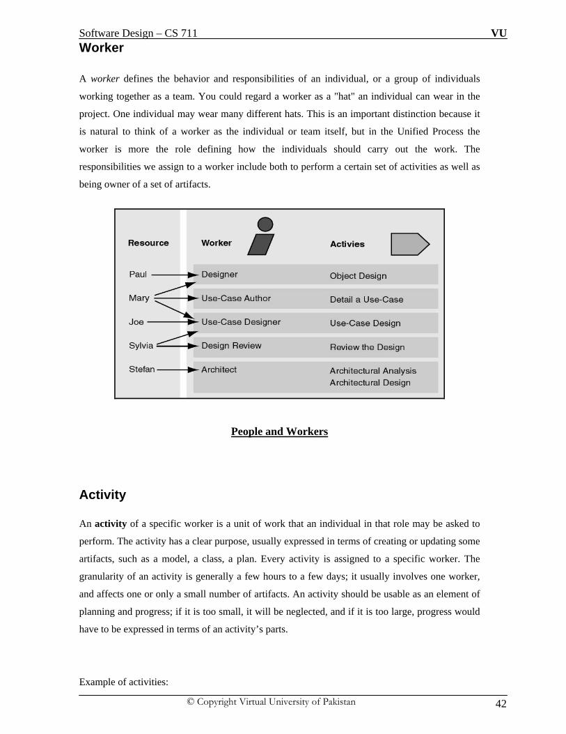
Activities, Artifacts, and Workers
Workers, activities, and artifacts.
Software Design – CS 711 VU
© Copyright Virtual University of Pakistan 42
Worker A worker defines the behavior and responsibilities of an individual, or a group of individuals
working together as a team. You could regard a worker as a "hat" an individual can wear in the
project. One individual may wear many different hats. This is an important distinction because it
is natural to think of a worker as the individual or team itself, but in the Unified Process the
worker is more the role defining how the individuals should carry out the work. The
responsibilities we assign to a worker include both to perform a certain set of activities as well as
being owner of a set of artifacts.
People and Workers
Activity An activity of a specific worker is a unit of work that an individual in that role may be asked to
perform. The activity has a clear purpose, usually expressed in terms of creating or updating some
artifacts, such as a model, a class, a plan. Every activity is assigned to a specific worker. The
granularity of an activity is generally a few hours to a few days; it usually involves one worker,
and affects one or only a small number of artifacts. An activity should be usable as an element of
planning and progress; if it is too small, it will be neglected, and if it is too large, progress would
have to be expressed in terms of an activity’s parts.
Example of activities:

Software Design – CS 711 VU
© Copyright Virtual University of Pakistan 43
Plan an iteration, for the Worker: Project Manager
Find use cases and actors, for the Worker: System Analyst
Review the design, for the Worker: Design Reviewer
Execute performance test, for the Worker: Performance Tester
Artifact An artifact is a piece of information that is produced, modified, or used by a process. Artifacts are
the tangible products of the project, the things the project produces or uses while working towards
the final product. Artifacts are used as input by workers to perform an activity, and are the result
or output of such activities. In object-oriented design terms, as activities are operations on an
active object (the worker), artifacts are the parameters of these activities.
Artifacts may take various shapes or forms:
A model, such as the Use-Case Model or the Design Model
A model element, i.e. an element within a model, such as a class, a use case or a
subsystem
A document, such as Business Case or Software Architecture Document
Source code
Executables
Workflows A mere enumeration of all workers, activities and artifacts does not quite constitute a process. We
need a way to describe meaningful sequences of activities that produce some valuable result, and
to show interactions between workers. A workflow is a sequence of activities that produces a
result of observable value.

Software Design – CS 711 VU
© Copyright Virtual University of Pakistan 44
Example of workflow
Note that it is not always possible or practical to represent all of the dependencies between
activities. Often two activities are more tightly interwoven than shown, especially when they
involve the same worker or the same individual. People are not machines, and the workflow
cannot be interpreted literally as a program for people, to be followed exactly and mechanically.

Software Design – CS 711 VU
© Copyright Virtual University of Pakistan 45

Software Design – CS 711 VU
© Copyright Virtual University of Pakistan 46
LECTURE NO: 5
Objective: This chapter will provide the motivation for software design in a structured manner; software
design life cycle will be discussed in detail.
Motivation for Software Design
A little story The US standard railroad gauge (distance between the rails) is 4 feet, 8.5 inches. That's an
exceedingly odd number. Why was that gauge used? Because that's the way they built them in
England, and English expatriates built the US Railroads. Why did the English build them like
that? Because the first rail lines were built by the same people who built the pre-railroad
tramways, and that's the gauge they used. Why did "they" use that gauge then? Because the
people who built the tramways used the same jigs and tools that they used for building wagons,
which used that wheel spacing. Okay! Why did the wagons have that particular odd wheel
spacing? Well, if they tried to use any other spacing, the wagon wheels would break on some of
the old long distance roads in England, because that's the spacing of the wheel ruts. So who built
those old rutted roads? Imperial Rome built the first long distance roads in Europe (and England)
for their legions. The roads have been used ever since. And the rut in the roads? Roman war
chariots formed the initial ruts, which everyone else had to match for fear of destroying their
wagon wheels. Since the chariots were made for Imperial Rome, they were all alike in the matter
of wheel spacing. So the United States standard railroad gauge of 4 feet, 8.5 inches is derived
from the original specifications for an Imperial Roman war chariot.
Lesson learn: design usually stay for years
Introduction to Software Design As the size and complexity of software systems increases, the design problem goes beyond the
algorithms and data structures of the computation: designing and specifying the overall system
structure emerges as a new kind of problem. Structural issues include gross organization and

Software Design – CS 711 VU
© Copyright Virtual University of Pakistan 47
global control structure; protocols for communication, synchronization, and data access;
assignment of functionality to design elements; physical distribution; composition of design
elements; scaling and performance; and selection among design alternatives. This is the software
architecture level of design. There is a considerable body of work on this topic, including module
interconnection languages, templates and frameworks for systems that serve the needs of specific
domains, and formal models of component integration mechanisms. In addition, an implicit body
of work exists in the form of descriptive terms used informally to describe systems. And while
there is not currently a well-defined terminology or notation to characterize architectural
structures, good software engineers make common use of architectural principles when designing
complex software. Many of the principles represent rules of thumb or idiomatic patterns that have
emerged informally over time. Others are more carefully documented as industry and scientific
standards. It is increasingly clear that effective software engineering requires facility in
architectural software design. First, it is important to be able to recognize common paradigms so
that high-level relationships among systems can be understood and so that new systems can be
built as variations on old systems. Second, getting the right architecture is often crucial to the
success of a software system design; the wrong one can lead to disastrous results. Third, detailed
understanding of software architectures allows the engineer to make principled choices among
design alternatives. Fourth, an architectural system representation is often essential to the analysis
and description of the high level properties of a complex system.
Software design and SDLC

Software Design – CS 711 VU
© Copyright Virtual University of Pakistan 48
Structures are the most stable things in your system and they have to hold even after years.
Software design lays down a structure for the system and divides the future system in parts which
can be managed. If we do it right, we are awarded with further abstraction. The goals of software
design are to understand the different interrelationships between requirements and design so that
classification at different higher-level architectural patterns and their interrelationship to design
patterns can be achieved. It will enable us to decide on the adequacy of a specific architectural
pattern for a certain problem and will enable us know how and when to apply architectural
patterns to make a certain system design. Structured software design will help us in making the
transition from a logical design to a physical design by using UML to document a system design
and then we will be able to validate if a specific implementation is compliant with the intended
architecture.
The fact about software as compare to design of the other things in the world is if we able to
implement the requirement correctly or not we will be able to know it by the end of the project
but how stable is our design from maintenance view point? We will be able to know this after
many years. As shown below software without proper software design will lead to unstable design
and will be a maintenance nightmare as opposite to software with proper design process.
This is also a fact about software that software development is for once but software maintenance
is forever and it depend on design of the software how easier software maintenance would be both
in term of cost and time.

Software Design – CS 711 VU
© Copyright Virtual University of Pakistan 49
Software design Defined:
“The process of defining the architecture, components, interfaces, and other
characteristics of a system or component”
Architectural design:
“The process of defining a collection of hardware and software components and
their interfaces to establish the framework for the development of a computer
system”
Software design is an iterative process which keeps on improving as we understand the problem
domain as we design more; it is a complicated process so therefore it needed to be modeled
Similar to an architect’s blueprint. Architectural design of the software is the highest level of
software design from which detail level of design emerges as we further grilled the requirements
to develop an architectural model. A model is an abstraction of the underlying problem. Software
designs should be modeled, and expressed as a series of views by using modeling language such
as UML
Architectural Design Activities:
i. Hierarchical decomposition of the system into subsystems
ii. Determine components and assign to subsystems
iii. Determine relationships between components
iv. Define communication between components (Model of the system) architecture

Software Design – CS 711 VU
© Copyright Virtual University of Pakistan 50
Detailed Design
“The process of analyzing design alternatives and defining the architecture,
components, interfaces, and timing and sizing estimates for a system or component”
Detailed Design Activities:
i. Determine the components’ interfaces
ii. Determine the usage between components Specification of components
Software Architecture: According to Shaw and Garlan: “The Software Architecture of a system consists of a description of the system
elements, interactions between the system elements, patterns that guide the
system elements and constraints on the relationships between system
elements”
OR
“The software architecture of a program or computing system is the structure
or structures of the system, which comprise software elements, the externally
visible properties of those elements, and the relationships among them”

Software Design – CS 711 VU
© Copyright Virtual University of Pakistan 51
Architectural design provide us with a more abstract view of the overall software design, and its
helpful for communication and complexity management.
Problem: There is no standard definition
And another problem is the fact that “Change is the only constant” so it might happen that initial
architecture of the software may be changed drastically with the passage of time and may become
useless in the end.
Lehman‘s First Law of Software Evolution “A program that is used as an implementation of software specification reflects
some reality undergoes continual change or becomes progressively less useful.”
Result:
The System will change (or it will vanish)
Modeling as a Design Technique Designs are too complicated to develop from scratch; good designs tend to be build using model: 1) Abstract different views of the system
2) Build models using precise notations (e.g., UML)
3) Verify that the models satisfy the requirements
4) Gradually add details to transform the models into the design

Software Design – CS 711 VU
© Copyright Virtual University of Pakistan 52
LECTURE NO: 6 && 7
Objectives: In these two lectures we will discuss principles of the software design using design taxonomy as
discussed in lecture no 5
Software Design Components When we design the design of the software, we have to deal with three types of components that
make up the design of the software, these components are as follow:
i. Principle
ii. Criteria
iii. Techniques
i. Principle This component of the software design has multiple sub-components and out of these
subcomponents we have to decide and design the problem under discussion depending upon the
nature of the problem.

Software Design – CS 711 VU
© Copyright Virtual University of Pakistan 53
a. Abstraction As seen in the diagram above, abstraction is the root of the design principle so before actually
starting discussion let us try to find its practical meaning first using an example.
Myth about Abstraction
Our task is to design a management information system for a hospital; it should include
patient management, doctor’s management, laboratory management, inventory of
equipment and medicines.
i. Programmers Approach:
Let us first discuss the approach which will be followed by a typical programmer:
Typically programmer will start by saying and thinking about the technology aspect for
implementation without going into the details of design component of the system. This will
engage the programmer with technology aspect earlier in the design cycle where there will be a
not needed discussion between technological implications on to be designed software design!!
ii. System Architect Approach
The approach of System architect would be to forget the technology, first understand what to do
in detail then generate Requirement Specification (RS) and from RS generate Functional
specification (FS) and design document (DD) – This is “Abstraction”

Software Design – CS 711 VU
© Copyright Virtual University of Pakistan 54
Abstraction Defined:
“A view of an object that focuses on the information relevant to a particular
purpose and ignores the remainder of the information”
IEEE Standard 610.12-1990 The abstraction notion is central to understanding the representational requirements of Design
activities. Put very simply, the use of abstractions during design gives the designer freedom to
ignore certain details, for the time being, and to determine or design the "big picture" aspects of
his design. The use of abstractions allows the designer to freely shift its focus from one part of the
design to another or from one Level of Detail (LoD) to a different one. An abstraction is simply
an entity's representation with some of the details omitted. The omitted details can be attributes,
relationships among sub-entities or sub-entities. Abstraction is simply removal of unnecessary
details which will help to design a complex system, we must focus on identifying what about
that part other parts should know in order to design their part. Abstraction is the process or
result of generalization by reducing the information content of a concept or an observable
phenomenon, typically in order to retain only information which is relevant for a particular
purpose. It is a process by which higher concepts are derived from the usage and classification of
literal ("real" or "concrete") concepts, first principles (defined below), or other methods. An
"abstraction" (noun) is a concept that acts as super-categorical noun for all subordinate concepts,
and connects any related concepts as a group, field, or category. It may be formed by reducing
the information content of a concept or an observable phenomenon, typically to retain only
information which is relevant for a particular purpose. For example, abstracting a leather soccer
ball to the more general idea of a ball retains only the information on general ball attributes and
behavior, eliminating the characteristics of that particular ball.
First Principle In philosophy, a first principle is a basic, foundational proposition or assumption that cannot be
deduced from any other proposition or assumption. In mathematics, first principles are referred to
as axioms or postulates. Gödel's incompleteness theorems have been taken to prove, among other
things, that no system of axioms that describe the set of natural numbers can prove its own
validity - nor perhaps can it prove every truth about the natural numbers.

Software Design – CS 711 VU
© Copyright Virtual University of Pakistan 55
There are two levels of abstraction which is desired to be achieved to have a stable software
design of the system or problem under discussion.
i. External
ii. Internal
i. External Abstraction
In this type of abstraction we try to apply techniques and principles which help us to have a
system which include a stable communication mechanism between the different components of
the system, it will help the software architectures to transform complexity into structures to form
the basic design component of the system.
Decomposition: To achieve external abstraction rule of “Divide and Conquer” is usually applied so that the
systems should be reduced to minimal information required to represent a system. We split one
system into smaller components so that designing the components independently of each other
can be achieved. For the outside world the components are reduced to their interfaces. We don’t
design components to correspond to execution steps since design decisions usually transcend
execution time. We decompose so as to limit the effect of any one design decision on the rest of
the system because anything that soaks the system will be expensive to change. Decomposition
suggests that components should be specified by all information needed to use the component and
nothing more! The rule of “Keep it Simple” is to be followed.
There are 3 different types of decomposition which are discussed as below:
I. Subsystems - Horizontal
II. Layers – Vertical
III. Tree – Tree Shaped

Software Design – CS 711 VU
© Copyright Virtual University of Pakistan 56
I. Subsystems – Horizontal Decomposition
“A Subsystem is a secondary or subordinate system within a
system”
IEEE Standard 610.12-1990
This is most commonly used component to achieve external abstraction using decomposition.
A subsystem is a functionally cohesive grouping of classes that is a major part of a larger
aggregate system. They can be independently ordered, configured, or delivered and are related to
each other via dependency relations, and communicate with each other via well-defined
interfaces. The rule of thumb is to decompose a system by functional services i-e Database
Subsystem, User Interface Subsystem etc; so that related services are combined under one
component. We try to transform the set of requirement into a structured design in which there is
no relationship of parent / child or master detail etc; subsystem basically defines the executable
components typically represented by interfaces at implementation level for communication, the
essence of the subsystem is that logically related requirements are combined under one
component so that efficiency can be achieved as we move forward in software design process.
Identifying subsystems usually involves backtracking, evaluation and revision of various
solutions and it is important to get the decomposition right. The main advantage of subsystem is
that it subsystems implemented by different teams depending upon components but this should be
kept in mind that bad decomposition can lead to unworkable designs. The graphical
representation of Subsystem is shown below:

Software Design – CS 711 VU
© Copyright Virtual University of Pakistan 57
Sample Subsystem:
II. Layers – Vertical Decomposition
Decomposition of the system into smaller, more manageable units,that are layered hierarchically.
Each layer supplies one level of abstraction. A layer only uses services of the next underlying
layer. A layer supplies services to the next top layer as each layer can be tested independently
and can be substituted (machine independence).Layers helps to structure applications that can be
decomposed into groups of subtasks in which each group of subtasks is at a particular level of
abstraction. Imagine that you are designing a system whose dominant characteristic is a mix of
low- and high-level issues, where high-level operations rely on the lower-level ones. Some parts
of the system handle low-level issues such as hardware traps, sensor input, reading bits from a file
or electrical signals from a wire. At the other end of the spectrum there may be user-visible
functionality such as the interface of a multi-user game or high-level policies such as telephone
billing tariffs. A typical pattern of communication flow consists of requests moving from high to
low level, and answers to requests, incoming data or notification about events traveling in the
opposite direction. Such systems often also require some horizontal structuring that is orthogonal
to their vertical subdivision. This is the case where several operations are on the same level of
abstraction but are largely independent of each other.

Software Design – CS 711 VU
© Copyright Virtual University of Pakistan 58
OSI 7-layer model is a typical example of it.
The system specification provided describes the high-level tasks to some extent, and specifies the
target platform. Portability to other platforms is desired. Several external boundaries of the system
are specified a priority such as a functional interface to which your system must adhere. The
mapping of high-level tasks onto the platform is not straightforward mostly because they are too
complex to be implemented directly using services provided by the platform. In such a case you
need to balance the following forces:
i. Late source code changes should not ripple through the system. They should be confined
to one component and not affect others. Interfaces should be stable, and may even be
prescribed by a standards body.
ii. Parts of the system should be exchangeable. Components should be able to be replaced by
alternative implementations without affecting the rest of the system. A low-level
platform may be given but may be subject to change in the future. While such
fundamental changes usually require code changes and recompilation,
reconfiguration of the system can also be done at run-time using an administration
interface. Adjusting cache or buffer sizes are examples of such a change. An extreme

Software Design – CS 711 VU
© Copyright Virtual University of Pakistan 59
form of exchangeability might be a client component dynamically switching to a
different implementation of a service that may not have been available at start-up.
Design for change in general is a major facilitator of graceful system evolution.
iii. It may be necessary to build other systems at a later date with the same low-level issues
as the system you are currently designing.
iv. Similar responsibilities should be grouped to help understandability and maintainability.
Each component should be coherent, if one component implements divergent issues
its integrity may be lost. Grouping and coherence are conflicting at times.
v. There is no 'standard' component granularity.
vi. Complex components need further decomposition.
vii. Crossing component boundaries may impede performance, for example when a
substantial amount of data must be transferred over several boundaries, or where
there are many boundaries to cross.
The system will be built by a team of programmers, and work has to be subdivided along
clear boundaries and requirement that is often overlooked at the architectural design stage.
Graphical representation of Layered Architecture is as below:

Software Design – CS 711 VU
© Copyright Virtual University of Pakistan 60
Layer Rule From a high-level viewpoint the solution is extremely simple. Structure your system into an
appropriate number of layers and place them on top of each other. Start at the lowest level of
abstraction-ca11 it Layer 1. This is the base of your system. Work your way up the abstraction
ladder by putting Layer Jon top of Layer J -1 until you reach the top level of functionality-call it
Layer N. Note that this does not prescribe the order in which to actually design layers, it just gives
a conceptual view. It also does not prescribe whether an individual Layer J should be a complex
subsystem that needs further decomposition, or whether it should just translate requests from
Layer J + I to requests to Layer J -1 and make little contribution of Its own. It is however essential
that within an individual layer all constituent components work at the same level of abstraction.
Most of the services that Layer J provides are composed of services provided by Layer J -I. In
other words, the services of each layer implement a strategy for combining the services of the
layer below in a meaningful way. In addition, Layer J's services may depend on other services in
Layer J. Layer can request for services from exactly one layer below it and can respond to a
request of a layer exactly one layer above it. The main structural characteristic of the Layers
pattern is that the services of Layer J are only used by Layer J + I-there are no further direct
dependencies between layers. This structure can be compared with a stack, or even an onion.
Each individual layer shields its lower layers from direct access by higher layers.

Software Design – CS 711 VU
© Copyright Virtual University of Pakistan 61
For example:
Total Layers = N = 3
Legal Request = N-1
Legal Response = N+ 1
Dynamics: The following scenarios are classic examples for the dynamic behavior of layered applications.
This does not mean that you will encounter every scenario in every architecture. In simple layered
architectures you will only see the first scenario, but most layered applications Involve Scenarios
I and II. Due to space limitations we do not give object message sequence charts in this pattern.
Scenario I is probably the best-known one. A client issues a request to Layer N. Since Layer
N cannot carry out the request on its own, it calls the next Layer N -1 for supporting subtasks.
Layer N -1 provides these, in the process sending further requests to Layer N -2, and so on until
Layer 1 is reached. Here, the lowest-level services are finally performed. If necessary, replies to
the different requests are passed back up from Layer 1. A characteristic of such top-down
communication is that Layer J often translates a single request from Layer J+ 1 into several

Software Design – CS 711 VU
© Copyright Virtual University of Pakistan 62
requests to Layer J -1. This is due to the fact that Layer J is on a higher level of abstraction than
Layer J-l and has to map a high-level service onto more primitive ones.
Scenario II illustrates bottom-up communication-a chain of actions starts at Layer 1, for
example when a device driver detects input. The driver translates the input into an internal format
and reports it to Layer 2, which starts interpreting it, and so on. In this way data moves up through
the layers until it arrives at the highest layer. While top-down information and control flow are
often described as 'requests', bottom-up calls can be termed 'notifications'. As mentioned in
Scenario I, one top-down request often fans out to several requests in lower layers. In contrast,
several bottom-up notifications may either be condensed into a single notification higher in the
structure, or remain in a 1: 1 relationship.
Scenario III describes the situation where requests only travel through a subset of the layers.
A top-level request may only go to the next lower level N -1 if this level can satisfy the request.
An example of this is where level N -1 acts as a cache and a request from level N can be satisfied
without being sent all the way down to Layer 1 and from here to a remote server. Note that such
caching layers maintain state information, while layers that only forward requests are often
stateless. Stateless layers usually have the advantage of being simpler to program, particularly
with respect to reentrancy.
Scenario IV describes a situation similar to Scenario III. An event is detected in Layer 1, but
stops at Layer 3 instead of traveling all the way up to Layer N. In a communication protocol, for
example, a resend request may arrive from an impatient client who requested data some time ago.
In the meantime the server has already sent the answer, and the answer and the re-send request
cross. In this case, Layer 3 of the server side may notice this and intercept the re-send request
without further action.
Scenario V involves two stacks of N layers communicating with each other. This scenario is
well-known from communication protocols where the stacks are known as 'protocol stacks'. In the
following diagram, Layer N of the left stack issues a request. The request moves down through
the layers until it reaches Layer 1, is sent to Layer 1 of the right stack, and there moves up
through the layers of the right stack. The response to the request follows the reverse path until it
arrives at Layer N of the left stack.

Software Design – CS 711 VU
© Copyright Virtual University of Pakistan 63

Software Design – CS 711 VU
© Copyright Virtual University of Pakistan 64
III. Tree-Structures – Tree Shaped Decomposition
This is a hybrid decomposition which is a combination of subsystem and layers in which we can
start at the root node and each node can be reached in exactly one way. This type of
decomposition follow a tree structure in which there is always one fix starting point as opposed to
subsystems in which there was no fixed starting point; and each root node can have either a child
node or leaf node (terminal node). Usually the nodes can be placed in different layers a node can
be considered as the representative of his sub tree. This is a bit tricky decomposition because
decision to opt for this is not very clear because we need to identify the need for it by critically
analyzing the requirement because some portion of the requirements will be converted into
subsystems and subsystems will be placed in different layers but subsystems in the layers will
communicating to components of subsystems of next layer, what we need to understand is that it
will have properties of layers and subsystems in it as shown graphically below:

Software Design – CS 711 VU
© Copyright Virtual University of Pakistan 65
Problem Statement: An automated ticket issuing system is used by passengers at a railway station for multiple
purposes. The System should also allow reservation of seats and give some route information.
The passenger should be able to pay for the ticket at the counter also.
To Do Task: We have to design the architecture of the above system after selecting a specific
principle and proper assumptions.
Possible Solution: Subsystem
Possible Solution: Layered Architecture

Software Design – CS 711 VU
© Copyright Virtual University of Pakistan 66
ii. Internal Abstraction:
a. Modularization Software architecture embodies modularity; that is, software is divided into separately named and
addressable components, often called modules that are integrated to satisfy problem requirements.
It has been stated that "modularity is the single attribute of software that allows a program to be
intellectually manageable". Monolithic software (i.e., a large program composed of a single
module) cannot be easily grasped by a reader.
Modularization Defined:
“The process of breaking a system into components to facilitate design and
development; an element of modular programming”
This is very common and basic rule of programming and software design in which we break the
software requirements in such a say that the components can be identified so to promote
reusability and to localize the error. We need to achieve modularity because this will provide us
with the facility of identifying and rectifying the error without looking in the whole software
design / code rather we will look into a particular module to fix it. In software design, modular
design — or "modularity in design" — is an approach that subdivides a system into smaller parts
(modules) that can be independently created and then used in different systems to drive multiple
functionalities. A modular system can be characterized by the following:
"(1) Functional partitioning into discrete scalable, reusable modules consisting of
isolated, self-contained functional elements;
(2) Rigorous use of well-defined modular interfaces, including object-oriented
descriptions of module functionality;
(3) Ease of change to achieve technology transparency and, to the extent possible, make
use of industry standards for key interfaces."
Besides reduction in cost (due to lesser customization, and less learning time), and flexibility
in design, modularity offers other benefits such as augmentation (adding new solution by
Software Design – CS 711 VU
© Copyright Virtual University of Pakistan 67
merely plugging in a new module), and exclusion. Examples of modular systems are cars,
computers and high rise buildings. Earlier examples include railroad
signaling systems, telephone exchanges, pipe organs and electric power distribution systems.
Computers use modularity to overcome changing customer demands and to make the
manufacturing process more adaptive to change. Modular design is an attempt to combine
the advantages of standardization (high volume normally equals low manufacturing costs)
with those of customization. A downside to modularity (and this depends on the extent of
modularity) is that modular systems are not optimized for performance. This is usually due to
the cost of putting up interfaces between modules
i. Encapsulation “A view of a problem that extracts the essential information relevant to a particular
purpose and ignores the remainder of the information”
[IEEE, 1983]
Encapsulation is the grouping of related ideas into one unit, which can thereafter be referred to by
a single name. This is achieved by isolating a system function or a set of data and operations on
those data within a module by providing precise specifications for the modules. Common
elements of an abstraction are grouped together and separated from other components; e.g.an
Abstract Data Type.
Example – I
Simple digital alarm clock is a real-world object that a layman can use and understand. They can
understand what the alarm clock does, and how to use it through the provided interface (buttons
and screen), without having to understand every part inside of the clock. Similarly, if you
replaced the clock with non-digital model, the layman could continue to use it in the same way,
provided that the interface works the same.
Example –II
A relational database is encapsulated in the sense that its only public interface is a Query
language (SQL for example), which hides all the internal machinery and data structures of the
database management system.

Software Design – CS 711 VU
© Copyright Virtual University of Pakistan 68
ii. Information Hiding – It is not Encapsulation: The concept of modularity leads every software designer to a fundamental question: "How do we
decompose a software solution to obtain the best set of modules?"
The principle of information hiding suggests that modules be "characterized by design decisions
that (each) hides from all others." In other words, modules should be specified and designed so
that information (procedure and data) contained within a module is inaccessible to other modules
that have no need for such information. Hiding implies that effective modularity can be achieved
by defining a set of independent modules that communicate with one another only that
information necessary to achieve software function. Abstraction helps to define the procedural (or
informational) entities that make up the software. Hiding defines and enforces access constraints
to both procedural detail within a module and any local data structure used by the module. The
use of information hiding as a design criterion for modular systems provides the greatest benefits
when modifications are required during testing and later, during software maintenance. Because
most data and procedure are hidden from other parts of the software, inadvertent errors introduced
during modification are less likely to propagate to other locations within the software.
Information Hiding is software design technique to achieve internal abstraction using
modularization in which each module's interfaces reveal as little as possible about the module's
inner workings and other modules are prevented from using information about the module that is
not in the module's interface specification. Every module is characterized by its knowledge of a
design decision which it hides from all others. Its interface or definition was chosen to reveal as
little as possible about its inner workings. Information hiding gives the designer the freedom
to modify how the responsibility is fulfilled by a module/object. This is helpful when design
decisions are likely to change. Design decisions that are subject to change should be hidden
behind abstract interfaces. Components should communicate only through well-defined
interfaces. Each component is specified by as little information as possible. If internal details
change, client components should be minimally affected (it may not even require recompilation).

Software Design – CS 711 VU
© Copyright Virtual University of Pakistan 69
LECTURE NO: 8 and 9
Objective: This chapter will cover related concepts of lecture 8 and 9. We will start our discussion on criteria
component of the software design and will be discussing different criteria’s of software design
excluding cohesion and extensible.
Software Design Criteria: When we design a software design, we need to understand the criteria beside principles which
should be followed to achieve a good software design. As shown in the diagram below Criteria
and Techniques are software design components which we will be discussing.
i. Complete
This software design criteria refer to the view that each component has all relevant
features within the abstraction; a general interface can be reused.
ii. Sufficient
Each component has all the features needed for a sensible and efficient usage within the
abstraction. The interface is as small as possible. Minimum possible interface is to be
selected
iii. Plausible
The decomposition of modules can be easily and intuitively be understood. Complexity is
not a criterion for a good software design.
iv. Homogeneous:
All the layers / subsystems should focus in same problem set. A minimal set of required
information should be included; the principle of information hiding is to be implemented
Example:
While calculating the annual interest on savings bank should not include details
about customer Education!!!

Software Design – CS 711 VU
© Copyright Virtual University of Pakistan 70
v. Focused
Separation of concerns Principle (SOC)
When designing software, there are usually certain requirements or considerations to be
carried out so that the software comes up to the expectations placed on it. These requirements or
considerations are called concerns. As an example of different concerns, a CRM system may
have concerns such as managing customers and their contacts, managing events, persistence of
data, reporting, security, logging, comprehensibility, maintainability and integration to existing
systems. Some of the concerns will be implemented as simple business logic; others may be
related with the quality of the software.
Type of Concerns: If we think of our CRM system, concerns such as managing customers, their contacts and events
are the core functionality of the system. They are called core concerns. In object oriented
systems, the core concerns can be separated of each other in their respective objects. On the other
hand, concerns like security and logging span multiple objects. Logging has to be done in
methods all over the system. These concerns that crosscut multiple modules are called
crosscutting concerns. In object-oriented systems, crosscutting concerns break the
separation of concerns: the crosscutting concerns cannot be studied in isolation of other concerns,
and while studying core concerns the crosscutting concerns are always present.
There may be tight coupling between core concerns and crosscutting concerns. One of the
symptoms of the tight coupling is that if there is a change in some crosscutting concern, many
little changes have to be made to many objects. This is because the crosscutting concern is
scattered in multiple core modules. There are two kinds of code scattering, duplicating and
complementary scattering. In duplicating scattering, identical piece of code is added to many
different modules. In complementary scattering, several modules implement complementary parts
of the concern. In addition to code scattering, when a module handles multiple concerns
simultaneously, code tangling arises. The nature of crosscutting concerns is inherent. Crosscutting
concerns cannot be handled well with an object-oriented language, not even by improving the
design. Object-oriented programming is just not sufficient for managing crosscutting concerns
SOC is a general principle in software engineering introduced by Dijkstra and Parnas as an
answer to control the complexity of ever-growing programs. In a nutshell, it promotes the
separation of different interests in a problem, solving them separately without requiring detailed
knowledge of the other parts, and finally combining them into one result. In practice, this

Software Design – CS 711 VU
© Copyright Virtual University of Pakistan 71
principle actually corresponds with finding the right decomposition or modularization of a
problem. Hereby, allowing for the modules to be expressed in different representations (even
within the same application) might help to facilitate their solution. Over the years, the quest for
better and more advanced representations has lead to different technologies, among which the
well-established modularization techniques such as functional decomposition and object-
orientation. While the principle formerly typically served to structure the functionality of
programs, it has lately also been applied to separate functional and nonfunctional requirements.
Examples of such non-functional requirements are distribution, fault-tolerance and security. Such
concerns are often hard to factor out in separate modules using classical object oriented
techniques. The code responsible for fault-tolerant behavior for instance is not well-separated in
one class or method, but cuts across many classes and methods. To separate such crosscutting
concerns, new separation or modularization techniques are necessary. This principle is
recognition of the need for human beings to work within a limited context. As descibed by G. A.
Miller the human mind is limited to dealing with approximately seven units of data at a time. A
unit is something that a person has learned to deal with as a whole - a single abstraction or
concept. Although human capacity for forming abstractions appears to be unlimited, it takes time
and repetitive use for an abstraction to become a useful tool; that is, to serve as a unit. When
specifying the behavior of a data structure component, there are often two concerns that need to
be dealt with: basic functionality and support for data integrity. A data structure component is
often easier to use if these two concerns are divided as much as possible into separate sets of
client functions. It is certainly helpful to clients if the client documentation treats the two
concerns separately. Further, implementation documentation and algorithm descriptions can profit
from separate treatment of basic algorithms and modifications for data integrity and exception
handling. There is another reason for the importance of separation of concerns. Software
engineers must deal with complex values in attempting to optimize the quality of a product. From
the study of algorithmic complexity, we can learn an important lesson. There are often efficient
algorithms for optimizing a single measurable quantity, but problems requiring optimization of a
combination of quantities are almost always NP-complete. Although it is not a proven fact, most
experts in complexity theory believe that NP-complete problems cannot be solved by algorithms
that run in polynomial time. In view of this, it makes sense to separate handling of different
values. This can be done either by dealing with different values at different times in the software
development process, or by structuring the design so that responsibility for achieving different
values is assigned to different components.
.Appling SOC principle: Applying the principle of separation of concerns to software design can result in a number of
residual benefits. First, the lack of duplication and singularity of purpose of the individual

Software Design – CS 711 VU
© Copyright Virtual University of Pakistan 72
components render the overall system easier to maintain. Second, the system as a whole becomes
more stable as a byproduct of the increased maintainability. Third, the strategies required to
ensure each component only concerns itself with a single set of cohesive responsibilities often
result in natural extensibility points. Forth, the decoupling which results from requiring
components to focus on a single purpose leads to components which are more easily reused in
other systems, or different contexts within the same system. Fifth, the increase in maintainability
and extensibility can have a major impact on the marketability and adoption rate of the system.
The principle of separation of concerns can also be of benefit when applied to business
organizations. Within large companies, ensuring that groups and sub-organizations are assigned a
unique set of cohesive responsibilities helps to facilitate overall business goals by minimizing the
coordination necessary between teams and maximizing the potential of each team to focus on
their collective responsibility and center of competency. The principle of separation of concerns
can also improve problem resolution in enterprise wide systems. When responsibilities are
properly delineated, problem identification becomes easier, resolution becomes faster, and
personal accountability is increased. Each of these areas in turn contributes to an improved quality
control process. Whether organizations of people or software systems are in view, applying the
principle of separation of concerns can aid in the management of complexity by eliminating
unnecessary duplication and proper responsibility allocation.
Example:
i. Web Content Management
There are number of classes, html pages, and css files grouped as a presentation layer
concern, then those classes, files, etc should only change for UI reasons and never need to
change for other concerns such as a change in databases. On a more granular level within
the presentation layer, you could separate content, format, and style concerns by grouping
them into resource, html, and css files.
ii. If you have a class that gets a person’s name from the database and arranges the order of
the first, last, and middle names, then there are two reasons to change this component.
You would need to change the class to change how it got data from the database and you
would need to change the class to change the order of the names. If you separated these
two purposes into a data access class that fetched the data and a presentation class that
arranged the name order, then if one of the purposes needed a change, you would only need
to modify one class.

Software Design – CS 711 VU
© Copyright Virtual University of Pakistan 73
vi. Coupling / Cohesion
Coupling - Degree of dependence among components Coupling refers to how many dependencies there are between modules and the nature of the
links. A module which is highly coupled means that it has to use many other modules for its own
functionality to work. A highly coupled module is difficult to test on its own and since it uses
many other modules, there are interfaces between them which increases the likelihood of defects
Desired Coupling The Components should “Loosely Coupled”. Loose Coupling promotes “Separation of
concern”. Loose coupling means designing so that you hold connections among different parts of
a program to a minimum. This means encapsulation, information hiding and good abstractions in
class interfaces. This also makes the stuff easier to test, which is a Good Thing. Coupling is easier
to measure and understand, because it is more mechanical in nature and requires less
interpretation. Suppose there are three components A, B, and C. A’s behavior depends upon B in
some way (any way), A’s behavior depends upon C in some way, and the behavior of B and C do
not appear to depend upon anything else. That’s pretty much it, that’s the coupling of the system
according to our definition, and it’s the sort of thing that a machine can figure out by simple
measurement as shown in the diagram below:

Software Design – CS 711 VU
© Copyright Virtual University of Pakistan 74
Dependencies
If module A requires module B before it can be tested, but module B also requires module C, we
might think that developing C first is the answer. Often though, these dependencies are
interrelated so perhaps C also requires elements of A. For this reason, designing the modules can
be complex and requires us to think about how the modules are related together. We want to
reduce the dependencies but not at the expense of reproducing the functionality in two or more
places. For example, if there are 2 components A and B; and both of them need to access a
database, it would be sensible to put the functionality to handle a database in a single module and
allow A and B to use it, rather than building in that functionality to both A and B.
Level of Coupling: Level of coupling refers to depth of dependency between components, we can estimate the level
of coupling for a set of modules by considering each of the ``kinds'' of coupling listed below, one
at a time. It's not important that you determine the precise level of coupling for a given set of
modules - but it is important to decide whether this is ``unacceptably high,'' ``high but
unavoidable,'' ``acceptable,'' or ``ideal.''

Software Design – CS 711 VU
© Copyright Virtual University of Pakistan 75
i. Content Coupling
This is highest level of coupling and occurs if there are two (or more) modules and if one refers to
the ``inside'' - the ``internal'' or ``private'' part - of the other in some way.
i. Module A ``branches'' or ``falls through'' into Module B (by containing
a GOTO statement that transfers control somewhere into the middle of Module B);
ii. Module A refers to, or changes, Module B's internal (and, again, ``private'') data
iii. Module A changes one of the statements in Module B's object code.
This is also known as ``Pathological Coupling'' - and it could said with some justification that the
above examples do involve ``sick programming practices.'' Fortunately, high level programming
languages make these difficult - though you can certainly do these things using assembly
languages (or C). Optimization'' is sometimes cited as an excuse for these. This is
the only plausible excuse for these that one might think of - you might consider resorting to some
of these only after every other sensible strategy has failed to produce a program that meets the
system's performance requirements (long after you've re-implemented critical sections, used
hardware components instead of software where possible, etc.) However, optimization is often
unnecessary, and there are less troublesome things you can to do to improve program efficiency.
Since the above practices make proper testing difficult, and program maintenance almost
impossible, programming practices that introduce ``content coupling'' should be regarded as a last
resort (and ideally, never be used).
Example:
If there is a software program and part of program handles lookup for customer based on the data
provided by the client. One component (function or method) is handling data lookup feature and
another component is handling the property of adding new customer as of when needed. In new
customer component data structure is processed in which data is stored of the new customer.
When we are searching the customer data and customer is not found, lookup component
adds customer by directly modifying the contents of the data structure containing
customer data (new customer). This is a very high level of coupling in which one
component is directly modifying the content of another component and this is not wanted
in any software design.

Software Design – CS 711 VU
© Copyright Virtual University of Pakistan 76
Improvement:
When customer not found, component calls the AddCustomer () method that is responsible for
maintaining customer data rather than directly modifying data structure.
ii. Common Coupling Common coupling occurs when modules communicate using global data areas (i.e., universal
common data areas). For example, programming allows the developer to declare a data element
as external, enabling it to be accessed by all modules. Common coupling is also known
as “Global coupling”. We can say that two components share data using Global data structures
and Common blocks.
Example: Process control component maintains current data about state of operation. It gets data from
multiple sources and then supplies data to multiple sink. Each source process writes directly to
global data store. Each sink process reads directly from global data store. The diagrammatic
representation is as below:
In the above scenario there can be a situation where sink might see the inconsistent value of
variable a, if one source is writing the value of variable a and sink read it and while sink is
reading the values another source may change it so it implies that sink is having inconsistent
value of shared variable a. We want to avoid such a situation so that sink should have consistent
value of variable a

Software Design – CS 711 VU
© Copyright Virtual University of Pakistan 77
An improvement is suggested to reduce the level of coupling that exists between the components,
due to high level of coupling that is a danger of inconsistent data in the application. The improved
solution suggest that there should a component responsible for reading the value of the shared
variable, rather than any component directly reading the value of shared variable and it will be the
responsibility of the data manager to maintain the consistent view of the shared variable. The
suggested solution is shown below:
iii. Control Coupling – Moderate Coupling
Two modules exhibit control coupling if one (``module A'') passes to the other (``module B'') a
piece of information that is intended to control the internal logic of the other. This will often be a
value used in a test for a case statement, if-then statement, or while loop, in module B's source
code. This is perfectly acceptable. However, the program architecture (as shown by the structure
chart) should make it clear that module A does control module B in this way - preferably by
having module A call module B directly, or vice-versa. Then, when the system is combined
together (``integrated'') and tested, the two modules will be combined together, and tested as one
unit, relatively early in the process - so that any problems arising from this control coupling'' will
be detected early on. This may be either good or bad, depending on situation. It is bad when
component must be aware of internal structure and logic of another module and it is good if
parameters allow factoring and reuse of functionality.

Software Design – CS 711 VU
© Copyright Virtual University of Pakistan 78
Example of Control Coupling
In an example of control coupling, a module that retrieves either a customer name or an address
depending on the value of a flag is illustrated. As a rule of thumb, use descriptive flags (i.e., a flag
that describes a situation or condition, such as end-of-file or invalid-acct-num). Do not use
control flags (i.e., a flag that tells a module what to do, such as write-err-message).
iv. Stamp Coupling – Low Level Coupling Stamp coupling is when modules share a composite data structure and use only a part of it,
possibly a different part (e.g., passing a whole record to a function that only needs one field of it)
or Two modules (``A'' and ``B'') exhibit stamp coupling if one passes directly to the other a
``composite'' piece of data - that is, a piece of data with meaningful internal structure - such as
a record (or structure), array, or (pointer to) a list or tree.
Example -1 The print routine of the customer billing accepts a customer data structure (cid, customer name,
address, phone no, email address, NIC, cell no, passport no) as an argument, parses it, and prints
the name, address, and billing amount. The billing amount is retrieved on the basis of cid which
is passed as an argument in the module. Only cid, customer name and address is used other
attributes are not used or in other word they are not needed.

Software Design – CS 711 VU
© Copyright Virtual University of Pakistan 79
Improvement The print routine takes the customer name, address, and billing information as an argument rather
than taking the whole structure as input.
Example –II An example of stamp coupling illustrates a module that retrieves customer address using only
customer id which is extracted from a parameter named customer details.
As a rule of thumb, never pass a data structure containing many fields to a module that only needs
a few. Some of the practitioners of structured design do not make a distinction between the
passing of parameters in an unstructured format (as described under data coupling) and the
passing of parameters in a data structure (stamp coupling). The distinction between data and
stamp coupling is not relevant in object-oriented systems. Stamp coupling promotes the creation
of artificial data structures (i.e., bundling of unrelated data elements together in a
structure). Although this bundling is meant to reduce coupling between modules, it in fact
increases the coupling between modules. Data structures are appropriate as long as the data
bundled together is meaningful and related.

Software Design – CS 711 VU
© Copyright Virtual University of Pakistan 80
v. Data Coupling – Low Level of Coupling
Data coupling occurs between two modules when data are passed by parameters using a
simple argument list and every item in the list is used.
OR
Two modules exhibit data coupling if one calls the other directly and they communicate using
``parameters'' - a simple list of inputs and outputs (and inputs that are modified) --- with each
parameter being an ``elementary'' piece of data, such as an integer, floating point
number, boolean value, member of an enumerated set, character, or (maybe) character string.
The modules exhibit stamp coupling if ``composite'' data types are used for parameters as
well. Ideally, this (``data coupling'') is the usual type of interaction between modules that
need to communicate at all: Modules with higher levels of coupling this are only used ``when
necessary.'' A module sees only the data elements it requires. It is the best (i.e., loosest) form
of coupling.
Example:
An example of data coupling is illustrated as a module which retrieves customer address
using customer id and only customer id is passed as an argument in the retrieve customer
address module. There is no extra attributes passed to the customer address module.
A module can be difficult to maintain if many data elements are passed. Too many parameters
can also indicate that a module has been poorly partitioned.

Software Design – CS 711 VU
© Copyright Virtual University of Pakistan 81
LECTURE 10 and 11
Objectives: In this chapter we will continue our discussion on design criteria and will be discussion concept
of cohesion in detail along with other software design criteria’s.
Cohesion: Principle of cohesion states that
“Things that belong together should be kept together”.
OR
“A measure of the closeness of the relationships between elements of a
component or "module" of a system”
The classic software design involves grouping data and the functions that act on it. We can
understand cohesion as a measure of how exclusively a methods interact with its data and how
exclusively the data is used by its methods. Cohesion has been extremely violated when a method
does not use any of the own data, when a method contains data that is not used by its own
functional elements, or when we have a function that deals only with the data of some other
method. Less egregious violations are common, where a function deals with some of its object’s
data but deals also with the data or functions exposed by another object. Lack of cohesion can
also be apparent from an external perspective: If you find that approaching any system
behavior via one path (command, screen, or web page) produces different results than
approaching the same behavior from a different path, you’ve been bitten by duplication as an
effect of poor cohesion. Good cohesion makes it possible to find functions easily. If methods
dealing with an address are located in the Address class, someone working with an address can
easily find the method they need and call it, instead of re-implementing it from scratch. If
functions that deal with an address are buried inside a mail-authoring component, a programmer
working outside of that component is unlikely to find them. He may end up rewriting the needed
behavior into the function he is working on so that afterward it is still not in the Address class.
Later his coworkers will re-implement it again. Without cohesion, duplication propagates.
Cohesion describes the focus of an individual software component. When a component has only

Software Design – CS 711 VU
© Copyright Virtual University of Pakistan 82
one responsibility, and therefore only one reason to change, then it has high cohesion. When a
component has many responsibilities, and therefore many reasons to change, then it has low
cohesion. Low cohesion is also noticeable when common responsibilities are spread throughout
unrelated components. Desired Cohesion: From software design view point always “High cohesion” is desirable because: it simplifies
correction, change and extension process. Components with high cohesion are more robust than
components with low cohesion. If a component representing an engine is responsible for both
accelerating and decelerating, then a change to the acceleration implementation could
inadvertently effect the deceleration implementation. If, however, the engine component is
responsible for acceleration and a separate brake component is responsible for deceleration, then a
change to the acceleration implementation in the engine component is unlikely to effect the
deceleration implementation in the brake component. Maintaining highly cohesive components is
easy. If all the logic dealing with deceleration is in the brake component, and that logic is not
spread throughout your system, then you won’t have to go hunting around your system whenever
you make changes to the deceleration logic. You only need to look at your break component.
Hence it simply reduces testing and it localizes the error to be detected easy as compared to low
cohesion.
Level or Range of Cohesion
i. Coincidental Cohesion – Lowest Cohesion

Software Design – CS 711 VU
© Copyright Virtual University of Pakistan 83
Modules with ``low'' levels of cohesion are highly undesirable and should be modified or
replaced. Coincidental cohesion occurs when parts of the component are only related by their
location in source code. A coincidentally cohesive module is one whose activities have no
meaningful relationship to one another. Coincidental cohesion is considered the worst level of
cohesion. Its activities are not related by flow of data or by flow of control. It is even less
cohesive than a logically cohesive module because its activities are not even in the same category.
Coincidental cohesion is very difficult to maintain. It requires the programmer to know the
internal details of the modules.
Example-I:
There is a mythological story associated with coincidental cohesion, a manager who is
responsible for maintaining a largish (say, 10000 line of code) C program reads about modularity
and how helpful it is in improving programming understanding of programs. The manager tells
his chief programmer to restructure the program (which is a one large subprogram) into modules.
He's going to get those benefits. The chief programmer, who thinks he has better uses for his time,
decides the fastest way to make modules out of the program is to take a ruler, measure down
every 6 inches in the program listing and draw a line. At each line, he inserts a call to a new
subprogram, and after that call creates the header for the new subprogram. These "modules"
exhibit ultimate coincidental cohesion because the line of code in the module is present mere due
to by incidence not by any logic or rule.
Example – II Suppose we have a module with multiple arguments, the module is performing the following
processing:
i. Print next line
ii. Reverse string of characters in second argument
iii. Add 7 to 5th argument
iv. Convert 4th argument to float
All the above functions have no relationship but they are there in the same
module by chance!!

Software Design – CS 711 VU
© Copyright Virtual University of Pakistan 84
ii. Logical Cohesion
In this level of cohesion elements of component are related logically and not functionally. Several
logically related elements are in the same component and one of the elements is selected by the
client component. A logically cohesive module performs several activities of the same general
category in which the activity or activities to be executed are selected by the invoking module.
``A logically cohesive module is one whose elements contribute to activities of the same general
category in which the activity or activities to be executed are selected from outside the module.''
A logically cohesive module contains a number of activities of the same general kind. To use the
module, we pick out just the piece(s) we need. Thus, a logically cohesive module is a grab bag of
activities. The activities, although different, are forced to share the one and only interface to the
module. The meaning of each parameter depends on which activity is being used; for certain
activities, some of the parameters will even be left blank (although the calling module still needs
to use them and to know their specific types)."
Example –I
Someone contemplating a journey might compile the following list:
a. Go by Car
b. Go by Train
c. Go by Boat
d. Go by Plane
What relates these activities? They're all means of transport, of course. But a crucial point is that
for any journey, a person must choose a specific subset of these modes of transport. It's unlikely
anyone would use them all on any particular journey.
Example- II
In performing an I/O operation a component reads inputs from tape, disk, and network. All the
code for these functions is in the same component. It is to note that operations are related, but the
functions are significantly different i-e the way to execute each function is different by the
different ways of performing I/O belong to same category that’s why they are in same module.

Software Design – CS 711 VU
© Copyright Virtual University of Pakistan 85
iii. TEMPORAL COHESION A temporally cohesive module is one which performs several activities that are related in time.
Temporally cohesive modules typically consist of partial activities whose only relationship to one
another is that they are all carried out at a specific time. A temporally cohesive module is one
supporting tasks that are all related in time. Often the activities in a temporally cohesive module
are more closely related to other modules than they are to each other. This type of cohesion also
results in tight coupling of data. It makes maintenance of a system more difficult. For example, if
a module requires only one piece of data to be initialized, it cannot call the global initialization
routine because that would reset data for the entire system. Instead, the developer has to decide
whether to remove the initialization code for the data it wants initialized to create a separate
initialization routine or to pass a parameter to the initialization routine indicating the piece of data
that is to be initialized. In either case, the existing code that invokes the initialization routine
must be modified. A better approach would have been to separate the temporally cohesive
initialization routine into functionally cohesive modules that initialize related data. Maintenance
is made more difficult because often the developer is tempted to share code among activities
within the module that are only related in time. As with procedurally cohesive modules, changes
made to one activity may affect another activity and it is more difficult to re-use a temporally
cohesive module.
Example – I Consider a module called "On_Really_Bad_Failure" that is invoked when a
Really_Bad_Failure happens. The module performs several tasks that are not functionally
similar or logically related, but all tasks need to happen at the moment when the failure occurs.
The module might
i. Cancel all outstanding requests for services
ii. Cut power to all assembly line machines
iii. Notify the operator console of the failure
iv. Make an entry in a database of failure records
Example -II
One of the most common examples of a temporally cohesive module is an initialization routine
that initializes data used by many modules throughout a system. All the parameter which require

Software Design – CS 711 VU
© Copyright Virtual University of Pakistan 86
initialization are set to their starting values irrespective of their functional relationship but due to
the fact they are related in term of time in which they should get initialized, they are knitted
together.
iv. Procedural Cohesion Elements of a component are related only to ensure a particular order of execution. Module with
(only) procedural cohesion is one supporting different and possibly unrelated activities, in which
control passes from one activity to the next. In this type of cohesion the elements are arranged
together in the module but with a condition that there is particular sequence to be followed to
execute them. Activities in a procedurally cohesive module are related by flow of execution rather
than by one problem-related function. They often contain a group of functions which make up
part of a larger function, but as a group perform no real function. Procedural cohesion may result
from an attempt to modularize some part of a flow chart. It is common in a procedurally cohesive
module for the input and output data to be unrelated. It is also common for such a module to pass
around partially edited data, switches, or flags. Because a procedurally cohesive module
performs no real function in itself, it is generally not a black box and not re-usable. Procedurally
cohesive modules are not as easily maintained as the modules using the high and middle levels of
cohesion
Example: Suppose there is a module which intents to repair the damaged record of the database and then
update the maintenance file. In this kind of application we can’t repair the damaged record
without reading it from the database; we can only repair the record after reading it from the
database. So the order the execution may be:
i. Read part number from data base
ii. Update repair record on maintenance file.
v. Communicational Cohesion
In communicational cohesion, module performs a series of actions related by a sequence of steps
to be followed by the product and all actions are performed on the same data. A communication
ally cohesive module is one which performs several functions on the same input or output data.
Communicational cohesion is an acceptable level of cohesion although it is not as good as
functional or sequential cohesion. Communicationally cohesive modules are easy to maintain. In

Software Design – CS 711 VU
© Copyright Virtual University of Pakistan 87
this type of cohesion other modules may require only part of the input or output data of the
communicationally cohesive module, making the unnecessary data redundant. The designer must
decide whether to discard the redundant data or create a second module passing only the
necessary data. But creating a second module causes duplication of code, making maintenance
more difficult. It is easier to share code within a communicationally cohesive module. This may
make it more difficult to make changes in one part of the code without affecting the functionality
of another part of the code.
Example: There is a student record in the database and from the student record multiple data is derived as
shown below:
vi. Sequential Cohesion A sequentially cohesive module contains activities where output data from one activity serves as
input data to the next activity. In general, a sequentially cohesive module has good coupling and
is easy to maintain. Sequentially cohesive modules are not as good candidates for re-use as are
functionally cohesive modules. This is because the activities contained within the sequentially
cohesive module generally only meet the requirements of that one module.
Example: Suppose we want to edit the customer data we need to perform the following tasks in sequence:
i. Retrieve customer Data
ii. Retrieve customer order

Software Design – CS 711 VU
© Copyright Virtual University of Pakistan 88
iii. Generate invoice
iv. Get and edit input data.
vii. Functional Cohesion – Highly cohesive A functionally cohesive module performs one and only one problem related task and every
essential element to a single computation is contained in the component. A functionally cohesive
module performs one and only one problem related task. This is ideal situation. Functionally
cohesive modules may be simple and perform one task, such as Read Customer Record. However,
a complex module with numerous sub modules may still be functionally cohesive if all of its
subordinate modules are only performed to carry out the task of the parent module. Functionally
cohesive modules are good candidates for re-use and systems built with functionally cohesive
modules are easily understood and, therefore, easier to maintain.
Example:
i. Drag Drop – an event triggered when a dragged object is dropped on a window,
ii. Sum Elements in Array,
iii. Read Customer Record,
iv. Calculate Net Pay
v. Assign Account Number
A complex module with numerous sub modules may still be functionally cohesive if all of its
subordinate modules are only performed to carry out the task of the parent module. For example,
Calculate Net Pay is functionally cohesive although it contains many different functions (e.g.,
calculate taxable deductions, calculate tax, and calculate CPP deduction).
Scale of Cohesion Vs Maintainability

Software Design – CS 711 VU
© Copyright Virtual University of Pakistan 89
Problem Statement
In the electric subsystem of the house where there are electric wires and appliances
running. Each appliance is having its own functionality and working. Each appliance is
having its own clear boundary into which it works.
To do Tasks:
i. Task is to identify level of coupling and cohesion in the scenario.
Solution: The given scenario is having no interdependency and each appliance is encapsulated within its
own boundary so the system is having low or no coupling but high level of cohesion.

Software Design – CS 711 VU
© Copyright Virtual University of Pakistan 90
Extensibility: As change is the only constant in the software, extendibility is the ease of adapting software
products to changes of specification. Extensibility (sometimes confused with forward
compatibility) is a software design principle where the implementation takes into consideration
future growth. It is a systemic measure of the ability to extend a system and the level of effort
required to implement the extension. Extensions can be through the addition of new functionality
or through modification of existing functionality. The central theme is to provide for change -
atypically enhancements - while minimizing impact to existing system functions. Although
forward compatibility and extensibility are similar, they are not the same. A forward compatible
system can accept data from a future version of itself and pick out the "known" part of the data.
An example is a text-only word processor ignoring picture data from a future version. An
extensible system is one that can be upgraded to fully handle the new data in the newer input
format. An example is the above mentioned word processor that can be upgraded to handle
picture data or a browser that needs added functionality to successfully load and display certain
document or file formats. In systems architecture, extensibility means the system is designed to
include hooks and mechanisms for expanding/enhancing the system with new capabilities without
having to make major changes to the system infrastructure. A good architecture provides the
design principles to ensure this—a roadmap for that portion of the road yet to be built. Note that
this usually means that capabilities and mechanisms must be built into the final delivery which
will not be used in that delivery and, indeed, may never be used. These excess capabilities are not
add-ons, but are necessary for maintainability and for avoiding early obsolescence.
Extensibility can also mean that a software system's behavior is modifiable at runtime, without
recompiling or changing the original source code. For example, a software system may have a
public Application Programming Interface that allows its behavior to be extended or modified by
people who don't have access to the original source code. The extra functionality can be provided
through either internally or externally coded extensions. A good software design is extensible and
is “open-ended”. It should solve a class of problems rather than a single instance. We should try
not to introduce what is immaterial and do not restrict what is irrelevant.
When is code extensible? There are three points at which code may be extended:

Software Design – CS 711 VU
© Copyright Virtual University of Pakistan 91
i. Compile time: change our source code to pick up new functionality; this may mean
adding new objects in new source code files and changing a factory function.
ii. Link time: arrange for changes to be picked up by the linker only; this may involve
some magic for new objects to be found, this can be self defeating as it inevitably
adds some obscurity to the code and possibly the makefiles too.
iii. Run time: dynamically loaded libraries where invented for this sort of thing. This can
also lead to obscurity in the code and usually makes debugging more complex
because you may have to wait for a library to be loaded before you can set break
points.
Although run time extension is truest to the idea of extendable code (because you don’t change
any of the existing code) I don’t think this buys much over a good compile-time extension system.
Run-time extension has its uses, such as in very dynamic systems, or non-stop applications but it
also complicates version tracking and configuration management. Sometimes the simplest thing is
to actually change some of the existing code. What is simplest and best depends on your
circumstances. Actually adding a line and recompiling will be the simplest solution.
How does extensibility work? Extensibility forces an approach to problems based on:
i. An upfront design which allows for addition
This is not to make a case for big up front design - quite the opposite in fact. Big up front design
assumes you can design the entire system up front. An extensible design accepts you can’t design
everything in advance, instead it provides a light framework which can allow for changes.
ii. Additions to be made in small, incremental steps
It is possible to produce an extensible system where the increments are big. We can give
command to execute a task, the commands could be small, “Put the kettle on”, rather than big:
“Take over the world.” If we make our commands too big we loose the element of extensibility,
the original problem is relocated inside a single command, which is effectively the entire system.
iii. Work elements to be separated into comprehensible units
Computers may run programs and source code may be compiled by a tool, but it is humans who
Software Design – CS 711 VU
© Copyright Virtual University of Pakistan 92
have to read and understand the system. There is a human factor to all of this, just because we can
write an immensely complex piece of code doesn’t mean we should. Anyone who has tried to
maintain by hand code that was originally produced by a code generator will have seen this
problem
How does extensibility help? To achieve these objectives we need to emphasis traditional software development issues: high
cohesion, low coupling, interface-implementation seperatation, minimize dependencies, and
develop build procedures to perform constant integration. This imposes a discipline on our
development. Extensible design fits well with the principles advocated by the agile methodologies
and iterative development. It allows functionality to be implemented in small steps as required,
thus it dove-tails with the minimal implementation, iterative development and frequent re-
prioritization often advocated by Agile development. In an extensible design we cannot afford for
one chunk to be too closely coupled with other chunks. The very essence of the system is
embracing change, it is accepted that additions will be continual, if one chunk of the system
resists such change it will make the whole design unworkable. Thus, we have placed the friction
of change centre stage. Normally we would rather not think about friction, it is a
problem we want to go away. By elevating the issue we are directly addressing it, the whole
system is designed around the idea of change through addition. If you are the kind of person who
likes new, green-field, system development this may sound pretty horrid. Basically, I’m
suggesting lay minimal foundations of specification, design and framework coding and making a
quick dash for the maintenance phase where you actually fit the functionality.
Extensibility is not “reuse” Extensibility a no magic bullet, it is just another technique in our toolbox for tackling software
development. Nor is it a code word for “reuse”. True, many of the properties emphasized by
extensibility is the same ones preached for reusable code: low coupling, high cohesion,
modularity, but these properties are advocated by most software engineering themes. Indeed, who
would argue for tightly coupled systems? It may be that, having an extensible system, with
malleable code allows your technology to be transferred to another project – many of the
properties required of an extensible system make transfer easier. One could easily imagine a word
processor system which offered a standard system and a beginner version with fewer options, plus
a professional version with more – But, such platform transfer is deriving from the minimalist
camp - “less is more” is the starting point. Extensible software development is no license to add
bells and whistles to your code in the hope that someone may use them. Quite the opposite,

Software Design – CS 711 VU
© Copyright Virtual University of Pakistan 93
extendable software should be free of bells and whistles; it should be minimal while allowing
itself to be extended. Striving for extensibility should impose a discipline on development leading
to fewer, cleaner, dependencies, well defined interfaces and abstractions with corresponding
reduction in coupling and higher cohesion.
Software Design – CS 711 VU
© Copyright Virtual University of Pakistan 94
LECTURE NO: 12 and 13
Objectives: In this chapter we will briefly review the object oriented programming concepts from
programming view point and we will implement these concepts in Java programming language
using Eclipse IDE.
Object Oriented Programming Concepts: To execute the sample programs below you need to download the following software’s from the
mentioned websites:
i. Java Runtime Environment (JRE)
URL:
http://www.oracle.com/technetwork/java/javase/downloads/jre-6u25-download-346243.html
ii. Eclipse IDE
URL: http://www.eclipse.org/
After downloading the mentioned software, install JRE and unzip Eclipse and place it on any drive
like C or D. To execute eclipse click on the Eclipse icon available in the folder.
i. Objects: Objects are key to understanding object-oriented technology. Look around right now and you'll
find many examples of real-world objects: your dog, your desk, your television set, your bicycle.
Real-world objects share two characteristics: They all have state and behavior. Human have state
(name, color, race) and behavior (walk, eat, talk). Bicycles also have state (current gear, current
pedal cadence, and current speed) and behavior (changing gear, changing pedal cadence, applying
brakes). Identifying the state and behavior for real-world objects is a great way to begin thinking
in terms of object-oriented programming. If we observe the real-world objects that are in our
immediate area. For each object that you see, ask yourself two questions: "What possible states
can this object be in?" and "What possible behavior can this object perform?". Make sure to write
down your observations. As you do, you'll notice that real-world objects vary in complexity; your
desktop lamp may have only two possible states (on and off) and two possible behaviors (turn on,
turn off), but your desktop radio might have additional states (on, off, current volume, current

Software Design – CS 711 VU
© Copyright Virtual University of Pakistan 95
station) and behavior (turn on, turn off, increase volume, decrease volume, seek, scan, and tune).
You may also notice that some objects, in turn, will also contain other objects. These real-world
observations all translate into the world of object-oriented programming.
Software objects are conceptually similar to real-world objects: they too consist of state and
related behavior. An object stores its state in fields (variables in some programming languages)
and exposes its behavior through methods(functions in some programming languages). Methods
operate on an object's internal state and serve as the primary mechanism for object-to-object
communication. Hiding internal state and requiring all interaction to be performed through an
object's methods is known as data encapsulation — a fundamental principle of object-oriented
programming.
i. Class In the real world, you'll often find many individual objects all of the same kind. A class is the
blueprint from which individual objects are created. A class contain variable to represent the
properties of the class and method which are used for processing the different business logic for
that particular class.
F example there may be thousands of other bicycles in existence, all of the same make and model.
Each bicycle was built from the same set of blueprints and therefore contains the same
components. In object-oriented terms, we say that your bicycle is an instance of the class of
objects known as bicycles. The following Bicycle class is one possible implementation of a
bicycle:
Sample Code in Java
class Bicycle {
int cadence = 0;
int speed = 0;
int gear = 1;
void changeCadence(int newValue) {
cadence = newValue;
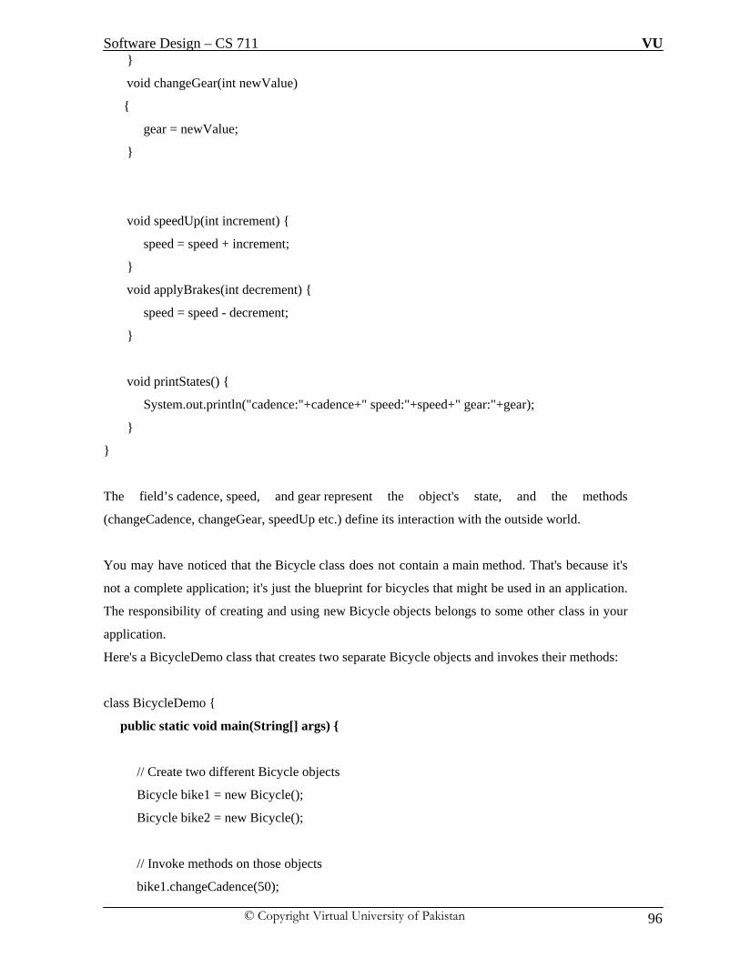
Software Design – CS 711 VU
© Copyright Virtual University of Pakistan 96
}
void changeGear(int newValue)
{
gear = newValue;
}
void speedUp(int increment) {
speed = speed + increment;
}
void applyBrakes(int decrement) {
speed = speed - decrement;
}
void printStates() {
System.out.println("cadence:"+cadence+" speed:"+speed+" gear:"+gear);
}
}
The field’s cadence, speed, and gear represent the object's state, and the methods
(changeCadence, changeGear, speedUp etc.) define its interaction with the outside world.
You may have noticed that the Bicycle class does not contain a main method. That's because it's
not a complete application; it's just the blueprint for bicycles that might be used in an application.
The responsibility of creating and using new Bicycle objects belongs to some other class in your
application.
Here's a BicycleDemo class that creates two separate Bicycle objects and invokes their methods:
class BicycleDemo {
public static void main(String[] args) {
// Create two different Bicycle objects
Bicycle bike1 = new Bicycle();
Bicycle bike2 = new Bicycle();
// Invoke methods on those objects
bike1.changeCadence(50);

Software Design – CS 711 VU
© Copyright Virtual University of Pakistan 97
bike1.speedUp(10);
bike1.changeGear(2);
bike1.printStates();
bike2.changeCadence(50);
bike2.speedUp(10);
bike2.changeGear(2);
bike2.changeCadence(40);
bike2.speedUp(10);
bike2.changeGear(3);
bike2.printStates();
}
}
The output of this test prints the ending pedal cadence, speed, and gear for the two bicycles:
cadence:50 speed:10 gear:2
cadence:40 speed:20 gear:3
ii. Inheritance
It implies the functionality of data sharing between super and sub class. All the data members and
methods of super class are available for use in sub class but not vice-versa. Subclass extends the
functionality of super class to use the base class methods. Different kinds of objects often have a
certain amount in common with each other. Mountain bikes, road bikes, and tandem bikes, for
example, all share the characteristics of bicycles (current speed, current pedal cadence, current
gear). Yet each also defines additional features that make them different: tandem bicycles have
two seats and two sets of handlebars; road bikes have drop handlebars; some mountain bikes have
an additional chain ring, giving them a lower gear ratio. Object-oriented programming allows
classes to inherit commonly used state and behavior from other classes. In this
example, Bicycle now becomes the superclass of MountainBike, RoadBike, and TandemBike. In
the Java programming language, each class is allowed to have one direct superclass, and each
superclass has the potential for an unlimited number of subclasses.
The syntax for creating a subclass is simple. At the beginning of your class declaration, use
the extends keyword, followed by the name of the class to inherit from:
public class MountainBike extends Bicycle {

Software Design – CS 711 VU
© Copyright Virtual University of Pakistan 98
// the MountainBike subclass has one field
public int seatHeight;
// the MountainBike subclass has one constructor
public MountainBike(int startHeight, int startCadence, int startSpeed, int startGear) {
super(startCadence, startSpeed, startGear);
seatHeight = startHeight;
}
// the MountainBike subclass has one method
public void setHeight(int newValue) {
seatHeight = newValue;
}
}
MountainBike inherits all the fields and methods of Bicycle and adds the field seatHeight and
a method to set it
iii. Abstract Classes
An abstract class is a class that is declared abstract—it may or may not include abstract methods.
Abstract classes cannot be instantiated, but they can be subclassed.
An abstract method is a method that is declared without an implementation (without braces, and
followed by a semicolon), like this:
abstract void moveTo(double deltaX, double deltaY);
If a class includes abstract methods, the class itself must be declared abstract, as in:
public abstract class GraphicObject {
// declare fields
// declare non-abstract methods
abstract void draw();
}

Software Design – CS 711 VU
© Copyright Virtual University of Pakistan 99
When an abstract class is subclassed, the subclass usually provides implementations for all of the
abstract methods in its parent class. However, if it does not, the subclass must also be
declared abstract.
Example: In an object-oriented drawing application, you can draw circles, rectangles, lines, Bezier curves,
and many other graphic objects. These objects all have certain states (for example: position,
orientation, line color, fill color) and behaviors (for example: moveTo, rotate, resize, draw) in
common. Some of these states and behaviors are the same for all graphic objects—for example:
position, fill color, and moveTo. Others require different implementations—for example, resize or
draw. All GraphicObjects must know how to draw or resize themselves; they just differ in how
they do it. This is a perfect situation for an abstract superclass. You can take advantage of the
similarities and declare all the graphic objects to inherit from the same abstract parent object—for
example, GraphicObject, as shown in the following figure.
First, you declare an abstract class, GraphicObject, to provide member variables and methods that
are wholly shared by all subclasses, such as the current position and
the moveTo method. GraphicObject also declares abstract methods for methods, such
as draw or resize, that need to be implemented by all subclasses but must be implemented in
different ways. The GraphicObject class can look something like this:
abstract class GraphicObject {
int x, y;
...
void moveTo(int newX, int newY) {
...
}
abstract void draw();
abstract void resize();

Software Design – CS 711 VU
© Copyright Virtual University of Pakistan 100
}
Each non-abstract subclass of GraphicObject, such as Circle and Rectangle, must provide
implementations for the draw and resize methods:
class Circle extends GraphicObject {
void draw() {
...
}
void resize() {
...
}
}
class Rectangle extends GraphicObject {
void draw() {
...
}
void resize() {
...
}}
iv. Overriding and Hiding Methods
Instance Methods An instance method in a subclass with the same signature (name, plus the number and the type of
its parameters) and return type as an instance method in the superclass overrides the superclass's
method. The ability of a subclass to override a method allows a class to inherit from a superclass
whose behavior is "close enough" and then to modify behavior as needed. The overriding method
has the same name, number and type of parameters, and return type as the method it overrides. An
overriding method can also return a subtype of the type returned by the overridden method. This
is called a covariant return type. When overriding a method, you might want to use
the @Override annotation that instructs the compiler that you intend to override a method in the
superclass. If, for some reason, the compiler detects that the method does not exist in one of the
superclasses, it will generate an error.
Class Methods If a subclass defines a class method with the same signature as a class method in the superclass,
the method in the subclass hides the one in the superclass.The distinction between hiding and

Software Design – CS 711 VU
© Copyright Virtual University of Pakistan 101
overriding has important implications. The version of the overridden method that gets invoked is
the one in the subclass. The version of the hidden method that gets invoked depends on whether it
is invoked from the superclass or the subclass. Let's look at an example that contains two classes.
The first is Animal, which contains one instance method and one class method:
public class Animal {
public static void testClassMethod() {
System.out.println("The class method in Animal.");
}
public void testInstanceMethod() {
System.out.println("The instance method in Animal.");
}
}
The second class, a subclass of Animal, is called Cat:
public class Cat extends Animal {
public static void testClassMethod() {
System.out.println("The class method in Cat.");
}
public void testInstanceMethod() {
System.out.println("The instance method in Cat.");
}
public static void main(String[] args) {
Cat myCat = new Cat();
Animal myAnimal = myCat;
Animal.testClassMethod();
myAnimal.testInstanceMethod();
}
}
The Cat class overrides the instance method in Animal and hides the class method in Animal.
The main method in this class creates an instance of Cat and calls testClassMethod() on the class
and testInstanceMethod() on the instance.
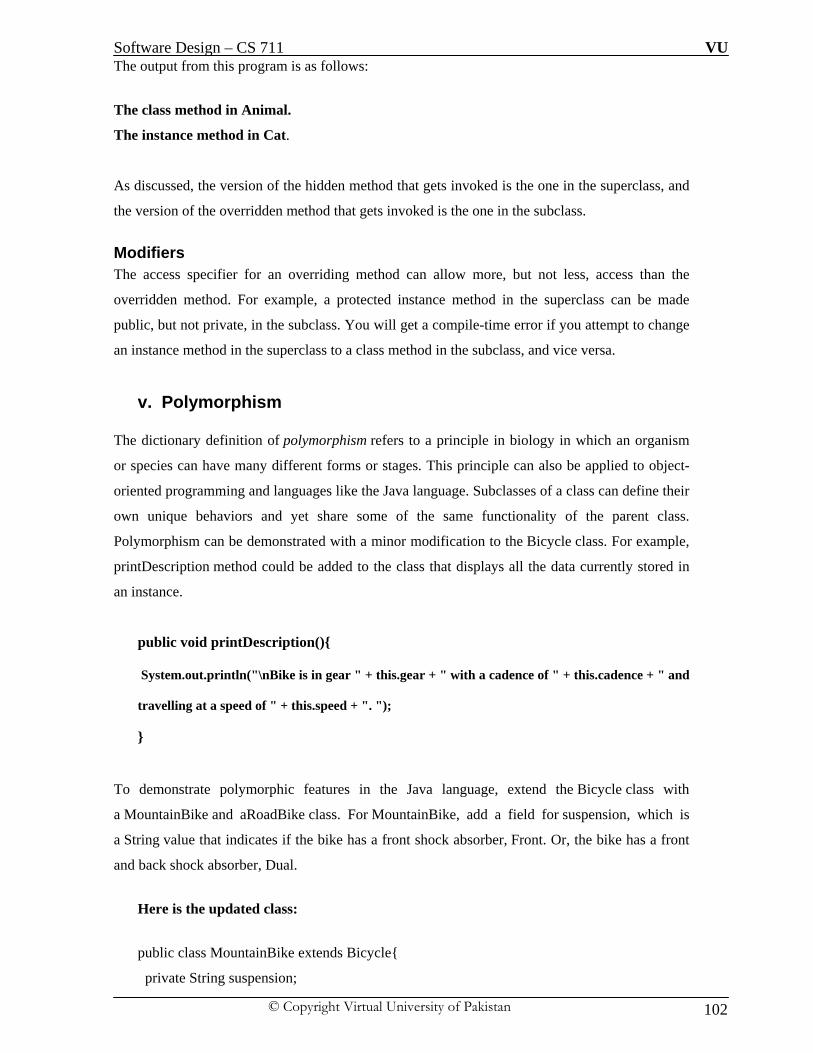
Software Design – CS 711 VU
© Copyright Virtual University of Pakistan 102
The output from this program is as follows:
The class method in Animal.
The instance method in Cat.
As discussed, the version of the hidden method that gets invoked is the one in the superclass, and
the version of the overridden method that gets invoked is the one in the subclass.
Modifiers The access specifier for an overriding method can allow more, but not less, access than the
overridden method. For example, a protected instance method in the superclass can be made
public, but not private, in the subclass. You will get a compile-time error if you attempt to change
an instance method in the superclass to a class method in the subclass, and vice versa.
v. Polymorphism
The dictionary definition of polymorphism refers to a principle in biology in which an organism
or species can have many different forms or stages. This principle can also be applied to object-
oriented programming and languages like the Java language. Subclasses of a class can define their
own unique behaviors and yet share some of the same functionality of the parent class.
Polymorphism can be demonstrated with a minor modification to the Bicycle class. For example,
printDescription method could be added to the class that displays all the data currently stored in
an instance.
public void printDescription(){
System.out.println("\nBike is in gear " + this.gear + " with a cadence of " + this.cadence + " and
travelling at a speed of " + this.speed + ". ");
}
To demonstrate polymorphic features in the Java language, extend the Bicycle class with
a MountainBike and aRoadBike class. For MountainBike, add a field for suspension, which is
a String value that indicates if the bike has a front shock absorber, Front. Or, the bike has a front
and back shock absorber, Dual.
Here is the updated class:
public class MountainBike extends Bicycle{
private String suspension;

Software Design – CS 711 VU
© Copyright Virtual University of Pakistan 103
public MountainBike(int startCadence, int startSpeed, int startGear, String suspensionType){
super(startCadence, startSpeed, startGear);
this.setSuspension(suspensionType);
}
public String getSuspension(){
return this.suspension;
}
public void setSuspension(String suspensionType){
this.suspension = suspensionType;
}
public void printDescription(){
super.printDescription();
System.out.println("The MountainBike has a " + getSuspension() + " suspension.");
}}
Note the overridden printDescription method. In addition to the information provided before,
additional data about the suspension is included to the output. Next, create
the RoadBike class. Because road or racing bikes have skinny tires, add an attribute to track
the tire width. Here is the RoadBike class:
public class RoadBike extends Bicycle{
private int tireWidth; // In millimeters (mm)
public RoadBike(int startCadence, int startSpeed, int startGear, int newTireWidth){
super(startCadence, startSpeed, startGear);
this.setTireWidth(newTireWidth);
}
public int getTireWidth(){
return this.tireWidth;
}
public void setTireWidth(int newTireWidth){
this.tireWidth = newTireWidth;

Software Design – CS 711 VU
© Copyright Virtual University of Pakistan 104
}
public void printDescription(){
super.printDescription();
System.out.println("The RoadBike has " + getTireWidth() + " MM tires.");
}}
Note that once again, the printDescription method has been overridden. This time,
information about the tire width is displayed. To summarize, there are three
classes: Bicycle, MountainBike, and RoadBike. The two subclasses override
theprintDescription method and print unique information.
Here is a test program that creates three Bicycle variables. Each variable is assigned to one of
the three bicycle classes. Each variable is then printed.
public class TestBikes {
public static void main(String[] args){
Bicycle bike01, bike02, bike03;
bike01 = new Bicycle(20, 10, 1);
bike02 = new MountainBike(20, 10, 5, "Dual");
bike03 = new RoadBike(40, 20, 8, 23);
bike01.printDescription();
bike02.printDescription();
bike03.printDescription();
}}
The following is the output from the test program:
Bike is in gear 1 with a cadence of 20 and travelling at a speed of 10.
Bike is in gear 5 with a cadence of 20 and travelling at a speed of 10.
The MountainBike has a Dual suspension.
Bike is in gear 8 with a cadence of 40 and travelling at a speed of 20.
The RoadBike has 23 MM tires.

Software Design – CS 711 VU
© Copyright Virtual University of Pakistan 105
The Java virtual machine (JVM) calls the appropriate method for the object that is referred to
in each variable. It does not call the method that is defined by the variable's type. This
behavior is referred to as virtual method invocation and demonstrates an aspect of the
important polymorphism features in the Java language.
vi. Interface
As we've already learned, objects define their interaction with the outside world through the
methods that they expose. Methods form the object's interface with the outside world; the buttons
on the front of your television set, for example, are the interface between you and the electrical
wiring on the other side of its plastic casing. You press the "power" button to turn the television
on and off. In its most common form, an interface is a group of related methods with empty
bodies.
An interface declaration consists of modifiers, the keyword interface, the interface name, a
comma-separated list of parent interfaces (if any), and the interface body. For example:
public interface GroupedInterface extends Interface1,Interface2, Interface3 {
// constant declarations
double E = 2.718282; // base of natural logarithms
// method signatures
void doSomething (int i, double x);
int doSomethingElse(String s);
}
The public access specifier indicates that the interface can be used by any class in any package. If
you do not specify that the interface is public, your interface will be accessible only to classes
defined in the same package as the interface.
An interface can extend other interfaces, just as a class can extend or subclass another class.
However, whereas a class can extend only one other class, an interface can extend any number of
interfaces. The interface declaration includes a comma-separated list of all the interfaces that it
extends.
The Interface Body The interface body contains method declarations for all the methods included in the interface. A
method declaration within an interface is followed by a semicolon, but no braces, because an

Software Design – CS 711 VU
© Copyright Virtual University of Pakistan 106
interface does not provide implementations for the methods declared within it. All methods
declared in an interface are implicitly public, so the public modifier can be omitted.An interface
can contain constant declarations in addition to method declarations. All constant values defined
in an interface are implicitly public, static, and final. Once again, these modifiers can be omitted.
To declare a class that implements an interface, you include an implements clause in the class
declaration. Your class can implement more than one interface, so the implements keyword is
followed by a comma-separated list of the interfaces implemented by the class.
By convention, the implements clause follows the extends clause, if there is one.
A Sample Interface, Relatable Consider an interface that defines how to compare the size of objects.
public interface Relatable {
// this (object calling isLargerThan) and
// other must be instances of the same class
// returns 1, 0, -1 if this is greater
// than, equal to, or less than other
public int isLargerThan(Relatable other);
}
If you want to be able to compare the size of similar objects, no matter what they are, the class
that instantiates them should implement Relatable. Any class can implement Relatable if there is
some way to compare the relative "size" of objects instantiated from the class. For strings, it could
be number of characters; for books, it could be number of pages; for students, it could be weight;
and so forth. For planar geometric objects, area would be a good choice (see
the RectanglePlus class that follows), while volume would work for three-dimensional geometric
objects. All such classes can implement theisLargerThan() method. If you know that a class
implements Relatable, then you know that you can compare the size of the objects instantiated
from that class.
Implementing the Relatable Interface Here is the Rectangle class written to implement Relatable.
public class RectanglePlus implements Relatable {
public int width = 0;
public int height = 0;

Software Design – CS 711 VU
© Copyright Virtual University of Pakistan 107
public Point origin;
// four constructors
public RectanglePlus() {
origin = new Point(0, 0);
}
public RectanglePlus(Point p) {
origin = p;
}
public RectanglePlus(int w, int h) {
origin = new Point(0, 0);
width = w;
height = h;
}
public RectanglePlus(Point p, int w, int h) {
origin = p;
width = w;
height = h;
}
// a method for moving the rectangle
public void move(int x, int y) {
origin.x = x;
origin.y = y;
}
// a method for computing the area of the rectangle
public int getArea() {
return width * height;
}
// a method required to implement the Relatable interface
public int isLargerThan(Relatable other) {
RectanglePlus otherRect = (RectanglePlus)other;
if (this.getArea() < otherRect.getArea())
return -1;
else if (this.getArea() > otherRect.getArea())

Software Design – CS 711 VU
© Copyright Virtual University of Pakistan 108
return 1;
else
return 0;
}
}
Because RectanglePlus implements Relatable, the size of any two RectanglePlus objects can be
compared.
Likewise another example of A bicycle's behavior, if specified as an interface, might appear as
follows:
interface Bicycle {
void changeCadence(int newValue); // wheel revolutions per minute
void changeGear(int newValue);
void speedUp(int increment);
void applyBrakes(int decrement);
}
To implement this interface, the name of your class would change (to a particular brand of
bicycle, for example, such asACMEBicycle), and you'd use the implements keyword in the class
declaration:
class ACMEBicycle implements Bicycle {
// remainder of this class implemented as before
}
Implementing an interface allows a class to become more formal about the behavior it promises to
provide. Interfaces form a contract between the class and the outside world, and this contract is
enforced at build time by the compiler. If your class claims to implement an interface, all methods
defined by that interface must appear in its source code before the class will successfully compile.

Software Design – CS 711 VU
© Copyright Virtual University of Pakistan 109
vii. Interface vs Abstract Classes Unlike interfaces, abstract classes can contain fields that are not static and final, and they can
contain implemented methods. Such abstract classes are similar to interfaces, except that they
provide a partial implementation, leaving it to subclasses to complete the implementation. If an
abstract class contains only abstract method declarations, it should be declared as an interface
instead. Multiple interfaces can be implemented by classes anywhere in the class hierarchy,
whether or not they are related to one another in any way. By comparison, abstract classes are
most commonly subclassed to share pieces of implementation. A single abstract class is
subclassed by similar classes that have a lot in common (the implemented parts of the abstract
class), but also have some differences (the abstract methods).
viii. Writing Final Classes and Methods You can declare some or all of a class's methods final. You use the final keyword in a method
declaration to indicate that the method cannot be overridden by subclasses. The Object class does
this—a number of its methods are final. You might wish to make a method final if it has an
implementation that should not be changed and it is critical to the consistent state of the object.
For example, you might want to make the getFirstPlayer method in thisChessAlgorithm class
final:
class ChessAlgorithm {
enum ChessPlayer { WHITE, BLACK }
...
final ChessPlayer getFirstPlayer() {
return ChessPlayer.WHITE;
}
...
}
Methods called from constructors should generally be declared final. If a constructor calls a non-
final method, a subclass may redefine that method with surprising or undesirable results. Note
that you can also declare an entire class final — this prevents the class from being subclassed.
This is particularly useful, for example, when creating an immutable class like the String class.
ix. Using this keyword Within an instance method or a constructor, this is a reference to the current object — the
object whose method or constructor is being called. You can refer to any member of the
current object from within an instance method or a constructor by using this.

Software Design – CS 711 VU
© Copyright Virtual University of Pakistan 110
Using this with a Field The most common reason for using the this keyword is because a field is shadowed by a
method or constructor parameter.
For example, there is a Point class written like this
public class Point {
public int x = 0;
public int y = 0;
//constructor
public Point(int a, int b) {
x = a;
y = b;
}
}
but it could have been written like this:
public class Point {
public int x = 0;
public int y = 0;
//constructor
public Point(int x, int y) {
this.x = x;
this.y = y;
}
}
Each argument to the constructor shadows one of the object's fields — inside the
constructor x is a local copy of the constructor's first argument. To refer to the Point field x,
the constructor must use this.x.
Using this with a Constructor From within a constructor, you can also use the this keyword to call another constructor in the
same class. Doing so is called an explicit constructor invocation.
public class Rectangle {
private int x, y;

Software Design – CS 711 VU
© Copyright Virtual University of Pakistan 111
private int width, height;
public Rectangle() {
this(0, 0, 0, 0);
}
public Rectangle(int width, int height) {
this(0, 0, width, height);
}
public Rectangle(int x, int y, int width, int height) {
this.x = x;
this.y = y;
this.width = width;
this.height = height;
}
...
}
This class contains a set of constructors. Each constructor initializes some or all of the rectangle's
member variables. The constructors provide a default value for any member variable whose initial
value is not provided by an argument. For example, the no-argument constructor calls the four-
argument constructor with four 0 values and the two-argument constructor calls the four-
argument constructor with two 0 values. As before, the compiler determines which constructor to
call, based on the number and the type of arguments. If present, the invocation of another
constructor must be the first line in the constructor.
x. Static methods
A Static method in Java is one that belongs to a class rather than an object of a class. Normal
methods of a class can be invoked only by using an object of the class but a Static method can be
invoked directly without object. In java we have two types of methods, instance
methods and static methods. Instance methods can be called by the object of a Class whereas
static method are called by the Class. When objects of a Class are created, they have their own
copy of instance methods and variables, stored in different memory locations. Static Methods and
variables are shared among all the objects of the Class, stored in one fixed location in memory.
Static methods cannot access instance variables or instance methods directly-they must use an
object reference. Also, class methods cannot use the this keyword as there is no instance
for this to refer to. Static methods can't use any instance variables. The this keyword can't be used
in a static methods. You can find it difficult to understand when to use a static method and when

Software Design – CS 711 VU
© Copyright Virtual University of Pakistan 112
not to use. If you have a better understanding of the instance methods and static methods then you
can know where to use instance method and static method. A static method can be accessed
without creating an instance of the class. If you try to use a non-static method and variable
defined in this class then the compiler will say that non-static variable or method cannot be
referenced from a static context. Static method can call only other static methods and static
variables defined in the class. The concept of static method will get more clear after this program.
First of all create a classHowToAccessStaticMethod. Now define two variables in it, one is
instance variable and other is class variable. Make one static method named staticMethod() and
second named as nonStaticMethod(). Now try to call both the method without constructing a
object of the class. You will find that only static method can be called this way.
public class HowToAccessStaticMethod{
int i;
static int j;
public static void staticMethod(){
System.out.println("you can access a static method this way");
}
public void nonStaticMethod(){
i=100;
j=1000;
System.out.println("Don't try to access a non static method");
}
public static void main(String[] args) {
//i=100;
j=1000;
//nonStaticMethod();
staticMethod();
}}
C:\java>java

Software Design – CS 711 VU
© Copyright Virtual University of Pakistan 113
LECTURE 14:
Motivation for Open Close Principle (OCP) A clever application design and the code writing part should take care of the frequent changes that
are done during the development and the maintaining phase of an application. Usually, many
changes are involved when a new functionality is added to an application. Those changes in the
existing code should be minimized, since it's assumed that the existing code is already unit tested
and changes in already written code might affect the existing functionality in an unwanted
manner. The Open Close Principle states that the design and writing of the code should be
done in a way that new functionality should be added with minimum changes in the existing code.
The design should be done in a way to allow the adding of new functionality as new classes,
keeping as much as possible existing code unchanged.
Open Close Principle (OCP): There are many heuristics associated with object oriented design. For example, “all member
variables should be private”, or “global variables should be avoided”, or “using run time type
identification (RTTI) is dangerous”. What is the source of these heuristics? What makes them
true? Are they always true? This column investigates the design principle that underlies these
heuristics -- the open-closed principle. As Ivar Jacobson said:
“All systems change during their life cycles. This must be borne in mind when
developing systems expected to last longer than the first version.”
How can we create designs that are stable in the face of change and that will last longer than the
first version?
Bertrand Meyer gave us guidance as long ago as 1988 when he coined the now famous
open-closed principle. To paraphrase him:

Software Design – CS 711 VU
© Copyright Virtual University of Pakistan 114
“Software entities like classes, modules and functions should be open for
extension but closed for modifications”
Meyer’s used inheritance to solve the apparent dilemma of the principle. His idea was that once
completed, the implementation of a class could only be modified to correct errors, but new or
changed features would require that a different class be created. When a single change to a
program results in a cascade of changes to dependent modules, that program exhibits the
undesirable attributes that we have come to associate with “bad” design. The program becomes
fragile, rigid, unpredictable and un-reusable. The open closed principle attacks this in a very
straightforward way. It says that you should design modules that never change. When
requirements change, you extend the behavior of such modules by adding new code, not by
changing old code that already works.
Modules that conform to the open-closed principle have two primary attributes:
I. They are “Open For Extension”
This means that the behavior of the module can be extended. That we can make the module
behave in new and different ways as the requirements of the application change, or to meet the
needs of new applications.
II. They are “Closed for Modification”
The source code of such a module is inviolate. No one is allowed to make source code changes to
it.
It would seem that these two attributes are at odds with each other. The normal way to extend the
behavior of a module is to make changes to that module. A module that cannot be changed is
normally thought to have a fixed behavior. How can these two opposing attributes be resolved?
The answer is abstraction. In Java or any other object-oriented programming language
(OOPL), it is possible to create abstractions that are fixed and yet represent an unbounded group
of possible behaviors. The abstractions are abstract base classes, and the unbounded group of
possible behaviors is represented by all the possible derivative classes.
It is not possible to have all the modules of a software system satisfy the OCP, but we should
attempt to minimize the number of modules that do not satisfy it. The Open-Closed Principle is
really the heart of OO design, conformance to this principle yields the greatest level of reusability
and maintainability.

Software Design – CS 711 VU
© Copyright Virtual University of Pakistan 115
Applying Open Close Principle (OCP): OCP is about arranging encapsulation in such a way that it’s effective, yet open enough to be
extensible. This is a compromise, i.e. “expose only the moving parts that need to change, hide
everything else”. The Open/Closed principle can be applied in be applied in object oriented
paradigms with the help of inheritance and polymorphism:
i. The interface of the module becomes an abstract class A
ii. If needed new Subclasses of A can be derived; these subclasses may extend A
These two steps are shown graphically below:
Before Applying OCP

Software Design – CS 711 VU
© Copyright Virtual University of Pakistan 116
After Applying OCP

Software Design – CS 711 VU
© Copyright Virtual University of Pakistan 117
Example - 1: We have to implement the banking system such that there will be an interface for the customer
and the bank will be handling different type of accounts in it like savings, current, Giro etc; each
type of account is having its own business logic to implement and policy. Bank foresees the
emergence of new type of accounts, we have to design the system which should take into
consideration the current requirements and should be able to adapt to future changes.
To Do Task:
We have to design the system using Open / Close Principle
Proposed Solution

Software Design – CS 711 VU
© Copyright Virtual University of Pakistan 118
Example - 2:
Given the Java code below, we need to identify whether it confirm to OCP or
not.
Java Code:
public interface Shape
{
void Draw();
}
public class Square extends Shape
{
public void Draw()
{
// draw a square
} }
public class Circle extends Shape
{
public void Draw()
{
// draw a circle
}}
public void DrawAllShapes(IList shapes)
{
foreach(Shape shape in shapes)
shape.Draw();
}

Software Design – CS 711 VU
© Copyright Virtual University of Pakistan 119
Solution: Note that if we want to extend the behavior of the DrawAllShapes function above to draw a new
kind of shape, all we need do is add a new derivative of the Shape class. The DrawAllShapes
function does not need to change. Thus, DrawAllShapes conforms to OCP. Its behavior can be
extended without modifying it. Indeed, adding a triangle class has absolutely no effect on any of
the modules shown here. Clearly, some part of the system must change in order to deal with the
triangle class, but all the code shown here is immune to the change.
In a real application, the Shape class would have many more methods. Yet adding a new shape to
the application is still quite simple, since all that is required is to create the new derivative and
implement all its functions. There is no need to hunt through all the application, looking for
places that require changes. This solution is not fragile.
Nor is the solution rigid. No existing source modules need to be modified, and no existing binary
modules need to be rebuilt – with one exception. The module that creates instances of the new
derivative of Shape must be modified. Typically, this is done by main, in some function called by
main, or in the method of some object created by main.
Finally, the solution is not immobile. DrawAllShapes can be reused by any application without
the need to bring Square or Circle along for the ride. Thus, the solution exhibits none of the
attributes of bad design mentioned.
This program conforms to OCP. It is changed by adding new code rather than by changing
existing code. Therefore, the program does not experience the cascade of changes exhibited by
nonconforming programs.
But consider what would happen to the DrawAllShapes function if we decided that all Circles
should be drawn before any Squares. The DrawAllShapes function is not closed against a change,
like this. To implement that change, we’ll have to go into DrawAllShapes and scan the list first
for Circles and then again for Squares.
Anticipation and “Natural” Structure
Had we anticipated this kind of change, we could have invented an abstraction that protected us
from it. The abstractions we chose above are more of a hindrance to this kind of change than a
help. You may find this surprising; after all, what could be more natural than a Shape base class
with Square and Circle derivatives? Why isn’t that natural, real-world model the best one to use?
Clearly, the answer is that model is not natural in a system in which ordering is coupled to shape
type.

Software Design – CS 711 VU
© Copyright Virtual University of Pakistan 120
This leads us to a disturbing conclusion. In general, no matter how “closed” a module is, there
will always be some kind of change against which it is not closed. There is no model that is
natural to all contexts! Since closure cannot be complete, it must be strategic. That is,
the designer must choose the kinds of changes against which to close the design, must guess at the
kinds of changes that are most likely, and then construct abstractions to protect against those
changes. This takes a certain amount of prescience derived from experience. Experienced
designers hope that they know the users and the industry well enough to judge the probability of
various kinds of changes. These designers then invoke OCP against the most probable changes.
Software Design – CS 711 VU
© Copyright Virtual University of Pakistan 121
LECTURE NO: 15
Objective: In this lecture we will have discussion on basics of Unified Modeling Language (UML) from
historical view point and on a broader spectrum we will discuss Use Case Diagram of UML
which will form the basis for other diagrams of UML.
An historical Perspective of Unified Modeling Language (UML): Identifiable object-oriented modeling languages began to appear between mid-1970 and the late
1980s as various methodologists experimented with different approaches to object-oriented
analysis and design. The number of identified modeling languages increased from less than 10 to
more than 50 during the period between 1989-1994. Many users of OO methods had trouble
finding complete satisfaction in any one modeling language, fueling the "method wars." By the
mid-1990s, new iterations of these methods began to appear and these methods began to
incorporate each other’s techniques, and a few clearly prominent methods emerged. The
development of UML began in late 1994 when Grady Booch and Jim Rumbaugh of Rational
Software Corporation began their work on unifying the Booch and OMT (Object Modeling
Technique) methods. In the Fall of 1995, Ivar Jacobson and his Objectory company joined
Rational and this unification effort, merging in the OOSE (Object-Oriented Software
Engineering) method.
Reason for creating Unified Modeling Language: There were three main reasons for creating Unified Modeling Language (UML):
i. These methods (Booch, OMT, and OOSE methods) were already evolving toward each
other independently. It made sense to continue that evolution together rather than apart,
eliminating the potential for any unnecessary and gratuitous differences that would
further confuse users.
ii. By unifying the semantics and notation, they could bring some stability to the object-
oriented marketplace, allowing projects to settle on one mature modeling language and
letting tool builder’s focus on delivering more useful features.

Software Design – CS 711 VU
© Copyright Virtual University of Pakistan 122
iii. They expected that their collaboration would yield improvements in all three earlier
methods, helping them to capture lessons learned and to address problems that none of
their methods previously handled well.
The efforts of Booch, Rumbaugh, and Jacobson resulted in the release of the UML 0.9 and 0.91
documents in June and October of 1996. During 1996, the UML authors invited and received
feedback from the general community. While Rational was bringing UML together, efforts were
being made on achieving the broader goal of an industry standard modeling language. In early
1995, Ivar Jacobson (then Chief Technology Officer of Objectory) and Richard Soley (then Chief
Technology Officer of OMG) decided to push harder to achieve standardization in the methods
marketplace. In June 1995, an OMG-hosted meeting of all major methodologists (or their
representatives) resulted in the first worldwide agreement to seek methodology standards, under
the aegis of the OMG process. During 1996, it became clear that several organizations saw UML
as strategic to their business. A Request for Proposal (RFP) issued by the Object Management
Group (OMG) provided the catalyst for these organizations to join forces around producing a
joint RFP response. Rational established the UML Partners consortium with several organizations
willing to dedicate resources to work toward a strong UML 1.0 definition. Those contributing
most to the UML 1.0 definition included: Digital Equipment Corp., HP, i-Logix, IntelliCorp,
IBM, ICON Computing, MCI Systemhouse, Microsoft, Oracle, Rational Software, TI, and
Unisys. This collaboration produced UML 1.0, a modeling language that was well defined,
expressive, powerful, and generally applicable. This was submitted to the OMG in January 1997
as an initial RFP response.January 1997 IBM, ObjecTime, Platinum Technology, Ptech, Taskon,
Reich Technologies and Softeam also submitted separate RFP responses to the OMG. These
companies joined the UML partners to contribute their ideas, and together the partners produced
the revised UML 1.1 response. The focus of the UML 1.1 release was to improve the clarity of the
UML 1.0 semantics and to incorporate contributions from the new partners. It was submitted to
the OMG for their consideration and adopted in the fall of 1997. UML has matured significantly
since UML 1.1. Several minor revisions (UML 1.3, 1.4, and 1.5) fixed shortcomings and bugs
with the first version of UML, followed by the UML 2.0 major revision that was adopted by the
OMG in 2005. Although UML 2.1 was never released as a formal specification, versions 2.1.1
and 2.1.2 appeared in 2007, followed by UML 2.2 in February 2009. UML 2.3 was formally
released in May 2010. UML 2.4 is in the beta stage as of today i-e May -2011
What is UML The Unified Modeling Language (UML) is a standard language for specifying, visualizing,
constructing, and documenting the artifacts of software systems, as well as for business modeling

Software Design – CS 711 VU
© Copyright Virtual University of Pakistan 123
and other non-software systems. The UML represents a collection of best engineering practices
that have proven successful in the modeling of large and complex systems.1 The UML is a very
important part of developing objects oriented software and the software development process.
The UML uses mostly graphical notations to express the design of software projects. Using the
UML helps project teams communicate, explore potential designs, and validate the architectural
design of the software.
Goals of UML
1. Provide users with a ready-to-use, expressive visual modeling language so they can
develop and exchange meaningful models.
2. Provide extensibility and specialization mechanisms to extend the core concepts.
3. Be independent of particular programming languages and development processes.
4. Provide a formal basis for understanding the modeling language.
5. Encourage the growth of the OO tools market.
6. Support higher-level development concepts such as collaborations, frameworks, patterns
and components.
7. Integrate best practices.
UML is not a development methodology rather it’s a collection of standard set of diagrams which
represents the state the system under consideration in graphical form from different view point.
This is collection of performing Object Oriented Analysis and Design of the system with the
support of a graphical representation of each phase of Software Development life cycles.

Software Design – CS 711 VU
© Copyright Virtual University of Pakistan 124
Diagrams overview: There are total of 14 diagrams in UML and these diagrams are broadly classified into two main groups
i. Structure
ii. Behavior
As shown in Figure 15.1 below:
Figure 15.1

Software Design – CS 711 VU
© Copyright Virtual University of Pakistan 125
As already mention in this chapter, UML provide different viewpoint of same system
under consideration, from view point perspective we can divide the diagrams in the UML
as shown in Figure 15.1 in 3 main categories:
i. Static
a. Use case diagram
b. Class diagram
ii. Dynamic
a. Activity diagram
b. Sequence diagram
c. Object diagram
d. State diagram
e. Collaboration diagram
iii. Implementation
a. Component diagram
b. Deployment diagram
Note: In this course as our main focus is not on UML diagrams, we are recapping the
important diagrams which are required in coming lectures. Hence we will be discussing
required diagrams (Diagrams in BOLD above) only for this course.

Software Design – CS 711 VU
© Copyright Virtual University of Pakistan 126
i. Static Diagrams:
a. Use Case Diagram (UCD):
In object oriented analysis and design methodology, UCD form the basis for identification and
documentation of requirement gathering phase in a procedural and graphical way. This diagrams
tends to represent the system holistically in a graphical way to represent the functional aspect of
the system along with functional users. For larger systems UCD consists of multiple use cases,
each use case usually represents a specific process of the system. Use cases form the base line
data of “Requirement Specification (RS)” document and for other diagrams to be discussed later
in the course. For tracking purposes each use case is given a use case number and depending upon
the template for RS generation different parameters about use case is stored. For example
commonly used RS templates are Volere Template or IEEE Requirement specification
template; and there are many more, large organizations usually have their own RS template. The
point which is to be discussed is that Use Cases form part of RS documents by identifying
Functional aspects in graphical and traceable form with each use case is usually assigned a unique
use case number and depending on RS template other relevant information is captured and stored
in a common repository for the project team to access.
Basic Concepts in Use Case Diagram:
i. Actor
An Actor is a role usually outside the boundary of a system that interacts directly with it as part of
a coherent work unit (a use case) of the system .One physical object (or class) may play several
different roles and be modeled by several actors. From this point one should not one assume that
Actors are humans and that misconception is natural by its naming convention. Actor is any
initiating entity to start the process. For example in Heat sensor system, sensors are actors that can
initiate a reaction. Actors are those roles which we can responsible for generating reaction from
the process within the system. There are cases when actors can belong within the existing system.

Software Design – CS 711 VU
© Copyright Virtual University of Pakistan 127
Notation to Represent an Actor:
ii. Use Case
These are the actions which are initiated by the actor for a particular process to be
completed. Each action correspond to one or single actor and vice – versa. We cannot
make it as a rule that an actor can initiate only one action. The main goal is to complete
the processes under consideration and there can be single step or multi-steps to complete
a particular process. One use case represents complete steps that are required for a
particular process to be completed.
Notation to Represent a Use Case:
Use case is represented by an Oval shape with the name of the step of the process which
complete a particular process
Name of Step of process

Software Design – CS 711 VU
© Copyright Virtual University of Pakistan 128
iii. Relationships:
There are relationships that exists between actors and use cases or both
a. Include
When multiple use cases share same functionality then it logical that rather than writing
the same functionality again and again, we can use the concept of re-usability to write the
common functionality once and include it as a part of required use case. One use case will
use the services of another use case. It is like the concept of Functions or Subroutines in
the programming. The base use cases are, in a sense, incomplete without the included use
case. Without adding the functionality of the common use case base use cases cannot
complete its process. It is represented by drawing a dotted directed arrow pointing
towards the included use case from all the use cases that include it.
<<includes>> <<includes>>
b. Extends
A significant alternative course of action exists within the use case. A use case may
extend a use case by adding new actions to the base use case. Typically used when
there are important, optional variations on the basic theme of the base use case. The
base use case is complete in and of itself. Extends relationship is dependent on the
base use case for its existence. We can say that extends is an additional which can be
used to supplement the basic functionality to fine tune the process. The flow of the
Use case-1
Common use case
Use case-2
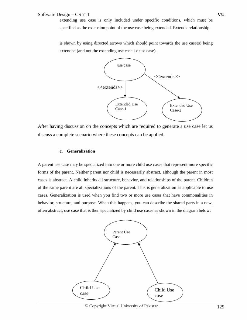
Software Design – CS 711 VU
© Copyright Virtual University of Pakistan 129
extending use case is only included under specific conditions, which must be
specified as the extension point of the use case being extended. Extends relationship
is shown by using directed arrows which should point towards the use case(s) being
extended (and not the extending use case i-e use case).
<<extends>> <<extends>>
After having discussion on the concepts which are required to generate a use case let us
discuss a complete scenario where these concepts can be applied.
c. Generalization
A parent use case may be specialized into one or more child use cases that represent more specific
forms of the parent. Neither parent nor child is necessarily abstract, although the parent in most
cases is abstract. A child inherits all structure, behavior, and relationships of the parent. Children
of the same parent are all specializations of the parent. This is generalization as applicable to use
cases. Generalization is used when you find two or more use cases that have commonalities in
behavior, structure, and purpose. When this happens, you can describe the shared parts in a new,
often abstract, use case that is then specialized by child use cases as shown in the diagram below:
use case
Extended Use Case-1
Extended Use Case-2
Parent Use Case
Child Use case
Child Use case

Software Design – CS 711 VU
© Copyright Virtual University of Pakistan 130
Things to avoid while identifying Use Cases:
A classic mistake made at this early stage of design is to go into technical detail and commit to a
specific user interface design or implementation technology. This is almost always the wrong
time to be making these kinds of low-level design decisions. We first need to understand what the
business logic of the interactions is, so we can focus on satisfying the business goal of the use
case. Essential use cases are a great technique for describing interactions in a way that is
independent of the technical implementation of the system

Software Design – CS 711 VU
© Copyright Virtual University of Pakistan 131
Scenario - 1:
For running an online store which contain different products several activities are taking place in
parallel to maintain, update and be competitive in the market with the help of effort of multiple
departments. Marketing staff can setup the promotional list of items; maintain the catalogue of
products whose promotion is to be emailed to the customers of the company. Sales staff processes
the order and in check the availability of the product in the current stock and also handles the
products which are returned by the customer either for repair or replacement. The online store has
an agreement with the courier company which collect the items to be delivered and in special
cases also deliver gift items to the clients. The process of placing the order by the customer can
perform the following steps under normal situation:
1. Customer enter login information
2. System display product menu
3. Customer add items to shopping cart
4. System display message indicate the item added to shopping cart
5. Customer proceed to checkout
6. System ask user provide shipping and billing information
7. Customer provide shipping and billing information
8. System confirm the shipping information, process the order and ship out the items
9. Customer receive the items
Task to do:
To Generate 2 possible use case diagrams. One possible solution is given below:

Software Design – CS 711 VU
© Copyright Virtual University of Pakistan 132
One Possible Solution:

Software Design – CS 711 VU
© Copyright Virtual University of Pakistan 133
Scenario -2:
Look at the diagram below, I have shown two use cases i-e Check out Option and
Review a product. Use in a online store can check out after completing shopping or
review a particular products but at certain point during that process in both the situations
user is prompted to login to proceed further, a condition is added to proceed further to
complete the processes. In the diagram below I have shown the brackets in both the use
cases which are showing common steps in both the use cases but at the end of both the
use cases they are required to login to proceed further.
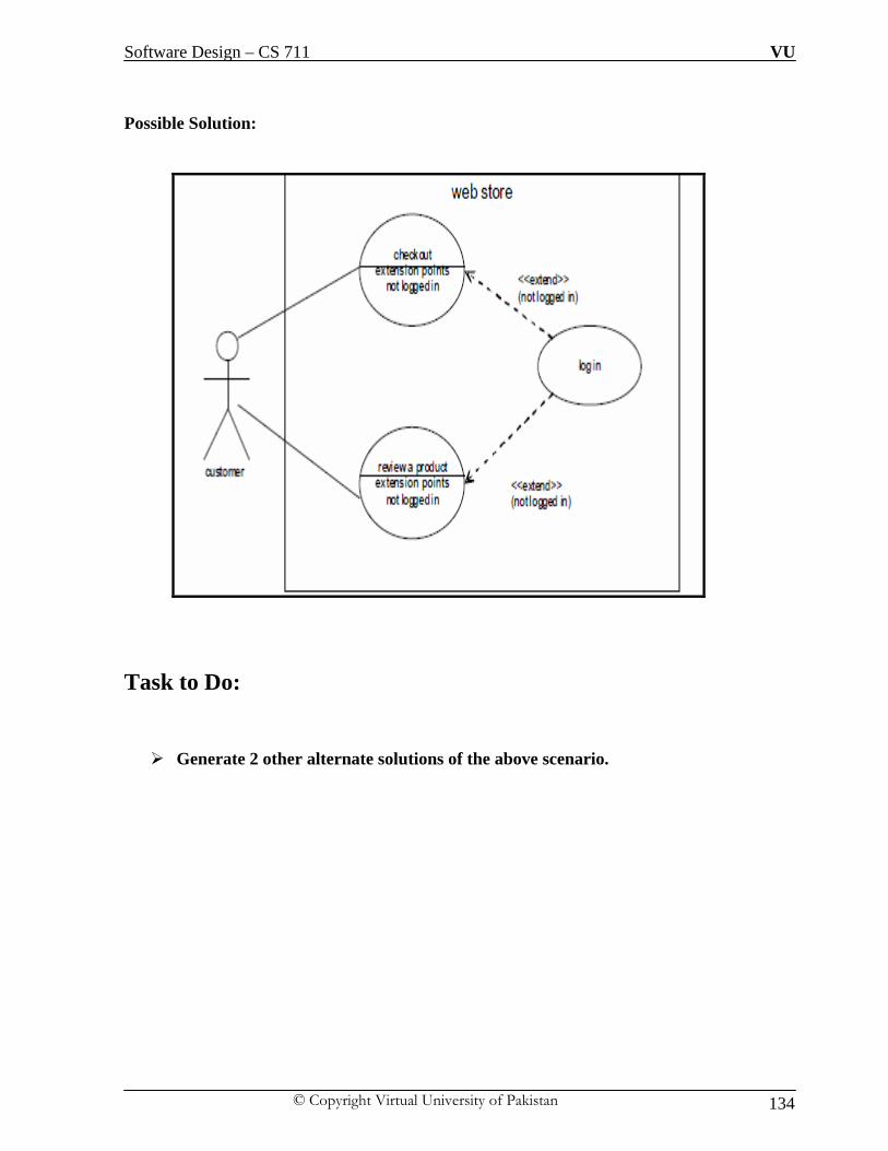
Software Design – CS 711 VU
© Copyright Virtual University of Pakistan 134
Possible Solution:
Task to Do:
Generate 2 other alternate solutions of the above scenario.

Software Design – CS 711 VU
© Copyright Virtual University of Pakistan 135
LECTURE NO: 16
Objectives: We will discuss the structure of class diagram, its components, relationship types that
exists in class diagram and we will cover association relationship with help of
comprehensive examples for each concept.
b. Class Diagram
This diagram is the next diagram in sequence of static category of UML diagrams.
This diagram derives its existence and functionality from Use Case Diagram. This is a
static structure diagram that shows the classes, attributes and methods along their
relationships. From this diagram we are a step closer toward implementation as
compare to UCD. From this diagram code will be generated beside other classes of
the respective framework if needed. There can be multiple versions of class diagram
during brain storming sessions but there will be only one final diagram of a particular
system against requirements which will be implemented, I mean to say that it is not
possible that we have multiple final versions of class diagrams to be implemented.
Each class will be accessed via it’s object which will actually exist in the memory for
the user to access a particular class, mechanism to access the class diagram may differ
in different programming language but class diagram will remain same so we are
having discussion without considering any technology aspect and as a reminder if you
will start thinking that you are implementing it in parallel then it will be
counterproductive to understand the concepts of class diagram.

Software Design – CS 711 VU
© Copyright Virtual University of Pakistan 136
Basic Concepts in Class Diagram
i. Class Structure
Class acts like a template (specification, blueprint) for a collection of objects that
share a common set of attributes and operations. It is a central modeling technique
which shows the various kinds of objects and their static relationships. It is
considered to be the richest notation oriented diagram in UML.
Class basically contains attributes (properties) and methods (Operations) that can be
applied on these attributes. Hence class is a combination of properties and processing
(business logic). The UML representation of a class is a rectangle containing three
compartments stacked vertically, as shown in the Figure below.
Ways to identify Classes:
Do the Noun Analysis: Go through the problem statement again and again and try to
figure out all the nouns that you come across. In our case some strong contenders for
the classes of the library management system would

Software Design – CS 711 VU
© Copyright Virtual University of Pakistan 137
Attributes (Variables)
Attributes are considered to be “What” part of the class diagram. They define the
properties relevant to that class only. While identifying attributes in a particular class,
it is not necessary that only objects of that class can access these attributes so for that
reason there is visibility restriction / rule applied with each attribute defined and as
shown in the table below:
This access level is necessary to define while defining the variables i-e Meta data of
variables are visibility scope. Variables are discouraged to be accessed directly by the
object rather access via its get or set methods is encouraged in Object Oriented Paradigm.
Operations (Methods)
Operations or commonly known as methods are the processing aspects which can be
performed by the class, operations can access variables as per table given above for the
attributes. Operations encapsulates the “How” aspect of the class i-e Business logic. As
in case of variables each prototype of method is preceded by its accessibility level.
Operations are often derived from actions verbs in use case descriptions. Some operations
will carry out processes to change or do calculations with the attributes of an object. Each
operation is having it’s unique signature with parameters’ as shown below:

Software Design – CS 711 VU
© Copyright Virtual University of Pakistan 138
Class Object: Class is structure which exists and can be accessed by declaring its objects or references by
allocating memory to the class. The size of the object depends on the attributes defined in the
class because object is just like a pointer which points to the memory location where class is
loaded to be accessed by the objects.

Software Design – CS 711 VU
© Copyright Virtual University of Pakistan 139
LECTURE NO: 17
Objective: This lecture will be a continuation of the contents of the previous lectures, in this lecture
we will discuss different types of relationships that exists between classes and how these
relationships have impact on the interaction among classes.
Relationships among classes
After having discussion on the basic structural issues of class diagram, now let us discuss the
interaction issues that exist between different classes of same class diagram. Interaction among
classes exists by the identification of the type of relationships between the classes. Classes don’t
work in isolation, the work in conjunction with other classes to re-use the functionality of the
other classes. Mainly there are 4 types of relationships that exist between classes of class diagram
as following:
i. Association
ii. Aggregation
iii. Composition
iv. Inheritance (Generalization / Specialization)
In this lecture we will discuss Association relationship in detail with the help of examples and
sample scenario. Due to the importance of these concepts intentionally i am spending more time
on these concepts because these will form the base for the coming contents later in the course.
It is pertinent to mention here that identification of classes, relationships among classes is
dependent on the requirements or the system under consideration so we have to identify the
classes and their relationship to full-fill the requirements of the “system strictly” otherwise every

Software Design – CS 711 VU
© Copyright Virtual University of Pakistan 140
class will have relationship with every other class because at the end of the day all the classes are
representing the same system.

Software Design – CS 711 VU
© Copyright Virtual University of Pakistan 141
i. Association:
This is a basic relationship that exists between classes; it is a structural relationship which
represents a binary relationship between objects. Associations are bi-directional i-e both
classes are involved in a relationship or uni-directional. The bi-directional association
relationship is shown by a line between two classes with a name of relationship on the
line as shown below:
Now the diagram above reflects the basic type of association that exists between Staff
member and Campaign class and it is a representation of bi-directional association between
participating classes. Both classes are aware of this relationship among them.
Uni-Direction Association: At time we need to mention the direction of the association that exists between classes because
we want to retrieve the value of class which is based on the value from another class. For
example, given a person’s full name, you can get the person’s telephone number, but not the other
way around. This mean one class is aware of the relationship but other class is not aware of this
relationship. Uni-direction association is shown by drawing a directed arrow from known class to
unknown class. In the diagram below PersonName class know about Telephone# class but not the
other way around.

Software Design – CS 711 VU
© Copyright Virtual University of Pakistan 142
Multiplicity:
It is the identification of the fact that how many instance(s) of a class can be initiated
against other class which is participating in the relationship; hence it represent cardinality
of the class in relationship to another class.It represent business constraint which will be
implemented in the software. There are multiple types of multiplicity values that can be
associated with the association, some of the commonly used types are shown below:
Optional (0 or 1)= 0..1
Exactly one = 1..1
Zero or more =0..*
One or more =1..*
A range of values= 1..6
A set of ranges =1..3,7..10,15,19..*
This concept is mostly not discussed in books and at times it is misunderstood due to lack of
depth we will try to address this issue.
In bi-directional association, relationship are also read and written in bi-directional way as shown
in the diagram below:
1 1..*
Rules to Read / write an Association:
Association # 1: Relationship from Class A to B
Association # 2: Relationship from Class B to A
Combination of Association 1 and Association 2 completes an Association.
Class A Class B

Software Design – CS 711 VU
© Copyright Virtual University of Pakistan 143
Another very important point to remember is that multiplicity is always written for a particular
class (Class A) from the line emerging from opposite class (Class B)
Multiplicity 1 emerging from Class A is actually representing multiplicity of Class B and
multiplicity 1...* emerging from Class B is actually representing multiplicity of Class A
Now we read the bi-directional association of the given above sample diagram:
Association # 1 (From A to B): Class A is having one or more (1...*) instance of B
Association # 2 (From B to A): Class B is having exactly one (1) instance of A
Another Example:

Software Design – CS 711 VU
© Copyright Virtual University of Pakistan 144
Tasks to Do:
i. Write Association for the diagram given below:
2..9 0..*
ii. Generate Use Case Diagram of the Class diagram given below:
Class A Class B

Software Design – CS 711 VU
© Copyright Virtual University of Pakistan 145
LECTURE NO: 18 && 19
Objective: This lecture will be a continuation of the contents of the previous lectures; in this chapter we will
cover the contents of 2 lectures (18 && 19) because we will be discussing aggregation,
composition associations in class diagram and it will be very constructive if we discuss them in
comparison with each other. Each concept will be supported by example or scenario.
i. Aggregation or “Has a “ Relationship: Aggregation is a specialized form of association i-e Weak Association; in which a particular class
diagram is creating by assembling classes. Aggregation is a special type of relationship used to
model a "whole to its parts" relationship. An association in which one class belongs to a
collection of classes
Whole-to-Part Relationship
In “Whole/part “relationship, where one object is the “whole”, and the other (on of)
the part(s)”. Part class is independent from the whole class’s lifecycle, this mean that we
construct a class diagram by using existing class but the existence of both the
participating classes in the relationship don’t have any sort dependence on each other
individual existence. Whole class has its own identity so does the part class. In an
aggregation relationship, the child class instance can outlive its parent class. Part class
can be a part of multiple whole classes.
Representing “Whole /Part” relationship:
To represent an aggregation relationship, you draw a solid line from the parent class to
the part class, and draw an unfilled diamond shape on the parent class's association end as
shown below:

Software Design – CS 711 VU
© Copyright Virtual University of Pakistan 146
The diagram above shows that a campaign contains advertisements but the existence of
advertisements is not necessary for the campaign, advert has their own existence which means
they don’t have a dependency relationship among them. As discussed advert can have a different
nature of relationship with another separate class. Here we also observe in the class diagram that
there is association also between two classes’ i-e 1 to Many (*); which implies association and
aggregation can also co-exist in the same relationship there is no binding on it.
Another Example:
This diagram shows association and aggregation between more than 2 classes (at a time 2
classes). Pictures belongs to folder but it is not necessary that picture should be contain inside a
folder they can also exist on the root like c:\ that’s why the association between them is
aggregation and same is true with picture to Word processing documents association.
Another Example
A catalogue object is a collection (aggregation) that consists of many product objects. However,
any particular product may appear in more than one catalogue. This is the case where part class
can belong to another whole class or have relationship with another class.

Software Design – CS 711 VU
© Copyright Virtual University of Pakistan 147
ii. Composition:
A composition relationship implies strong ownership of the part and the whole. Also
implies that if the whole is removed from the model, so is the part.It’s a strong
association. It contain Objects that live and die together. The composition aggregation
relationship is just another form of the aggregation relationship, but the child class's
instance lifecycle is dependent on the parent class's instance lifecycle. In a composition
relationship, the whole is responsible for the disposition of its parts, i.e. the composite
must manage the creation and destruction of its parts. As opposite to Aggregation the
existence of part class is only possible with existence of whole class. Another difference
is that part classes strictly belong to only one parent class. For example heart belong to
only one human body
Representing Composition relationship:
It is represented by a filled diamond shape from child to parent class with association Example -1: In the example given below, building consists of room where building is acting like
whole class and room is a part class and they are having composition relationship which
mean if building is destroyed then rooms will automatically be destroyed and rooms can’t
exists independently they must belong to a building, so it would be wrong if we create
aggregate relationship between two classes.

Software Design – CS 711 VU
© Copyright Virtual University of Pakistan 148
Example -2:
Consider the class diagram given below where order is placed and it contain different
order items (order details), each order detail is having product but every product will not
be a part of order item but for order item to exist it should have an order for it. So the
relationship between order and order item is of composition but between order item and
product is aggregation.

Software Design – CS 711 VU
© Copyright Virtual University of Pakistan 149
After having a discussion on composition and aggregation in detail let us compare them
by using following table.

Software Design – CS 711 VU
© Copyright Virtual University of Pakistan 150
Tasks to do:
i. Complete the following class diagram by creating appropriate relationships
between person-to-car, engine-to-car, person-to-Train, engine –to train, write
justification for your answer because just as a practice for exams, answer without
justification will not be considered to be true.

Software Design – CS 711 VU
© Copyright Virtual University of Pakistan 151
LECTURE NO: 20
Objective: This lecture will be a continuation of the contents of the previous lectures; in this lecture we will
discuss the concept of Inheritance (Generalization and Specialization) in detail in class diagram.
Each concept will be supported by example or scenario.
Inheritance (Generalization / Specialization)
This is a last type of main relationships that exists between classes of class diagrams. This
relationship represents parent /child or super type / sub type relationship in which all the attributes
and operations of super class (as per accessibility level discussed in previous lecture) are available
to be used by all the sub classes. The child always inherits the structure and behavior of the
parent. However, the child may also add new structure and behavior, or may modify the behavior
of the parent (by using overriding). At times we are faced with a situation where there are
multiple classes having some common attributes or methods among them and some different
attributes or methods, in such a situation rather than repeating the common behavior we define
common attributes and methods in super class and sub class can inherit them but we have to keep
this thing in mind that it should not be the case that sub type don’t have which is not common
among other sub types. Specific attributes / methods for sub class should exists also. The super
class which is having generic or common behavior to be inherited by its sub classes is known as
“Generalization” and sub classes having sub class specific attributes / methods is known as
“Specialization”
Notation to Represent Inheritance:
The triangle linking the classes shows inheritance; the connecting line between AdminStaff and
CreativeStaff indicates that they are “mutually exclusive” i-e Staff member can either be Admin
staff or Creative Staff but strictly not the both. However, all instances of AdminStaff and
CreativeStaff will have a staff#,name, startDate, while CreativeStaff will also have a qualification
attribute.

Software Design – CS 711 VU
© Copyright Virtual University of Pakistan 152
Similarly, the operation CalculateBonus () is declared in StaffMember, but is overridden in each
of its sub-classes.
For AdminStaff, the method uses data from StaffGrade to find out the salary rate and
calculate the bonus.
In the case of CreativeStaff, it uses data from the campaigns that the member of staff has
worked on to calculate the bonus.
Finding Inheritance: It is very important to under the way to find inheritance, at times it is very clear from the given
scenario but at time it is in abstract form we need to explicitly find it. There is not hard and fast
rules to identify and finding inheritance except practice but broadly speaking we can divide of this
into two main categories:
i. Top-Down
ii. Bottom-up

Software Design – CS 711 VU
© Copyright Virtual University of Pakistan 153
i. Top-down: we have a class, and we realize that we need to break it down into subclasses
which have different attributes and operations.
From the class diagram below it seems that there is no need to break the
advertisements (Advert) but when we perform a analysis then we find out that there
are multiple types of adverts each having its own properties methods and here we find
out 2nd level of inheritance between Press Advert is having 2 child which i-e Press
advert; is a child by itself.

Software Design – CS 711 VU
© Copyright Virtual University of Pakistan 154
ii. Bottom-up: we have several classes and we realize that they have attributes and
operations in common, so we group those attributes and operations together in a
common super-class. As shown below we have 2 separate classes having some
attributes and methods in common, the class diagram before inheritance is as below:
The class diagram after inheritance is shown below which show a common class
having common attributes and methods and sub classes are having only specific
attributes and subclasses also share attributes and method of super class i-e Loan
Item.

Software Design – CS 711 VU
© Copyright Virtual University of Pakistan 155
LECTURE NO: 21
Objective: This lecture will provide multiple sample scenario’s and solution of each scenario will be
discussed during the lecture because all the concepts which are discussed in the previous lectures
regarding class diagrams need practice using sample scenario’s.
Scenario # 1:
i. Suppose that you're writing a document in some of famous text processing tools, like
Microsoft Word for example. You can start typing a new document, or open an existing
one. You type a text by using your keyboard.
ii. Every document consists of several pages, and every page consists of header, document's
body or/and footer. In header and footer you may add date, time, page number, file
location e.t.c
iii. Document's body has sentences. Sentences are made up of words and punctual signs.
Words consists of letters, numbers and/or special characters. Also in the text you may
insert pictures and tables. Table consists of rows and columns. Every cell from table may
hold up text or pictures.
iv. After finishing the document, user can choose to save or to print the document.

Software Design – CS 711 VU
© Copyright Virtual University of Pakistan 156
Developing a Solution:
i. Extracting keywords from the scenario
document, text processing tool, MicrosoftWord, text, keyboard, header, footer, document's
body, date, time, page number, location of file, page, sentence, word, punctual sign, letter,
number, special character, picture, table, row, column, cell, user
Keywords in bold are candidate attributes, rest are nouns and are potential classes.
ii. Develop class structures (attributes and operations)
a. Document Class
A document will be the central class in our class diagram. Document has a several pages;
therefore a numberOfPages will be one of the attributes for the Document class. For the
operations we have: open (), save (), print () and new (). Every document consists of
pages. The Page will be also a candidate for the class.

Software Design – CS 711 VU
© Copyright Virtual University of Pakistan 157
b. Page Class
The Page class will hold pageNumber as an attribute, and operations allowed here
can be: newPage (), hideHeader () and hideFooter ().
c. BottomUp Class
This class contains Header and Footer Classes, the Header class and the Footer class have
common attributes:
I. date, time, pageNumber and fileLocation. These attributes are optional for every header
or footer and user may configure them. This will guide us that a common class can be
introduced. This will be a good time to make an inheritance.
II. Parent class will be BottomUp (this name is chosen because headers and footer appear in
upper and bottom parts of every page) and will hold common attributes for header and
footer, and these operations: display (), hide () and change (). Header and Footer classes
(children of this class) will have only operations: newHeader () and newFooter ().
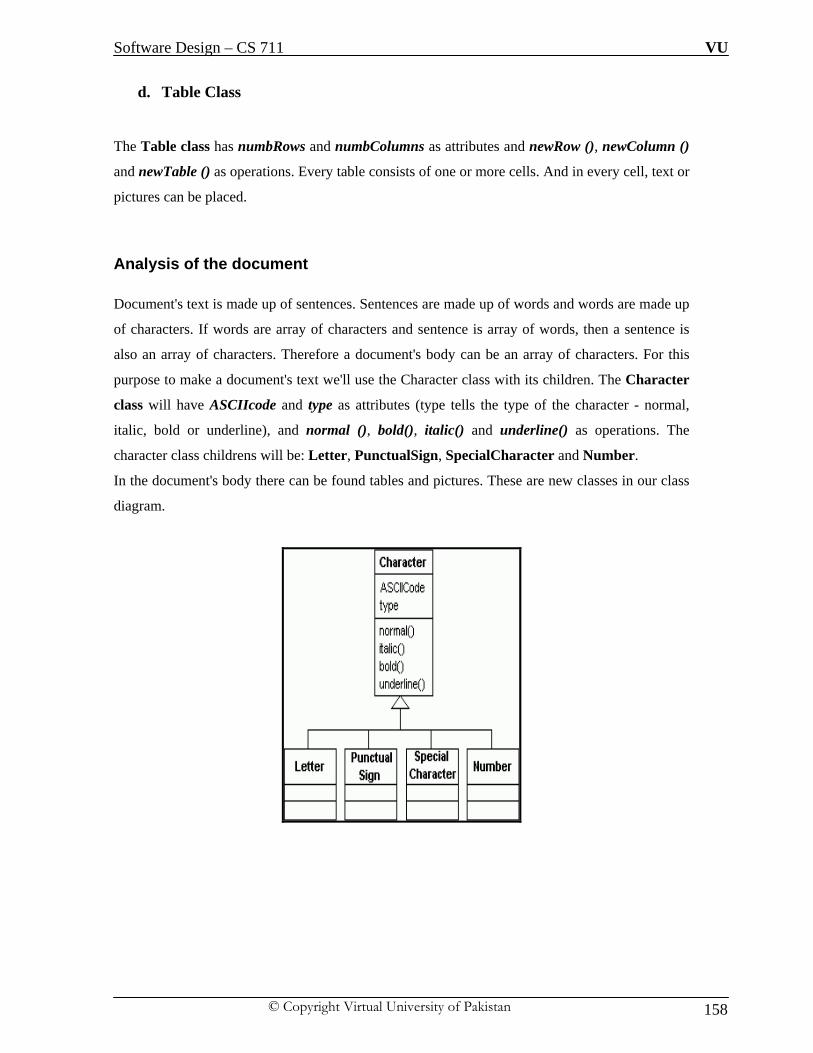
Software Design – CS 711 VU
© Copyright Virtual University of Pakistan 158
d. Table Class
The Table class has numbRows and numbColumns as attributes and newRow (), newColumn ()
and newTable () as operations. Every table consists of one or more cells. And in every cell, text or
pictures can be placed.
Analysis of the document Document's text is made up of sentences. Sentences are made up of words and words are made up
of characters. If words are array of characters and sentence is array of words, then a sentence is
also an array of characters. Therefore a document's body can be an array of characters. For this
purpose to make a document's text we'll use the Character class with its children. The Character
class will have ASCIIcode and type as attributes (type tells the type of the character - normal,
italic, bold or underline), and normal (), bold(), italic() and underline() as operations. The
character class childrens will be: Letter, PunctualSign, SpecialCharacter and Number.
In the document's body there can be found tables and pictures. These are new classes in our class
diagram.

Software Design – CS 711 VU
© Copyright Virtual University of Pakistan 159
Proposed Solution:

Software Design – CS 711 VU
© Copyright Virtual University of Pakistan 160
Scenario # 2:
i. We need to design a system to handle the world cup where there are multiple teams and
each team is having 11 players.
ii. Each team represents a country of its belonging.
iii. Countries qualify from zone, where each zone is having one or more countries in it.
iv. Each team is given a number of games in a specific city.
v. Referees are assigned to games.
vi. Hotel reservations are made in the city where teams play the game
Proposed Solution

Software Design – CS 711 VU
© Copyright Virtual University of Pakistan 161
LECTURE NO: 22 && 23
Objective: We will cover contents of two lectures in one chapter as these two lectures will be discussing
Activity diagram. We will discuss Dynamic Category of UML specifically Activity diagrams with
its notations in detail and at the end we will discuss a comprehensive example to understand the
concepts discussed.
Activity Diagram: Activity diagram belongs to the dynamic category of the UML diagrams, as the category suggest,
this diagram shows variation in the behavior of the system as it changes its state from one to
another. Typically activity diagram can be mapped with use cases because use cases shows
interactions between different processes and activity diagram can represents the logic of use case.
It can be discussed in conjunction with use case but due to different category I am intentionally
discussing it after class diagram. To show the logic of the process in step-wise manner activity
diagram can be very helpful. One activity diagram can be associated with one or multiple use
case(s). An activity diagram usually shows a business process or a software process as a flow of
work through a series of actions. People, software components, or computers can perform these
actions. In its basic form, an activity diagram is a simple and intuitive illustration of what happens
in a workflow, what activities can be done in parallel, and whether there are alternative paths
through the workflow.
Notations in Activity Diagram:
As common for most notations, the activity diagram notation has some elements that are
necessary for you to understand if you want to be “conversant” about activity diagrams. Those
elements are presented here. A basic activity diagram can have the following elements:
i. Activity States:
There are two states of the activity one is initial activity shown by filled circle and other final
activity shown with a border. Each activity should have one initial state but can have more than
one final state. An activity, also known as an activity state, on a UML Activity diagram typically
represents the invocation of an operation, a step in a business process, or an entire business
process. The rounded rectangles represent activities that occur during the work flows.

Software Design – CS 711 VU
© Copyright Virtual University of Pakistan 162
ii. Transitions:
Transitions that show what activity state follows after another. This type of transition is
sometimes referred to as a completion transition, since it differs from a transition in that it does
not require an explicit trigger event; it is triggered by the completion of the activity the activity
state represents. In case of transitions from one activity to another activity, directed arrow is used
to show the flow within one workflow.
iii. Decisions:
These are like branching situations for which set of guard conditions are defined. These guard
conditions control which transition of a set of alternative transitions that follows once the activity
has been completed. You may also use the decision icon to show where the threads merge again.
Decisions and guard conditions allow you to show alternative threads in the workflow of a
business use case.
Branch:
The branch describes what activities will take place based on a set of conditions. It is represented
by a diamond with one flow entering and several leaving. The flows leaving include conditions
although some modelers will not indicate the conditions if it is obvious. It is like if-then-else in
programming language.
Merge:
This type of decision is required when we need to terminate activity of parallel activities; it is
shown by a diamond with several flows entering and one leaving. It is represented by a diamond
with multiple flows (conditions) entering and there is only one outcome, there is no else part. The
implication is that one or more incoming flows must reach this point until processing continues,
based on any guards on the outgoing flow.
iv. Synchronization Bars (Fork, Join):
These bars can be used to show parallel subflows. Synchronization bars allow you to show
concurrent (parallel) threads in the workflow of a business use case.

Software Design – CS 711 VU
© Copyright Virtual University of Pakistan 163
Join:
Join Synchronization bar is used when several flows are entering in a process and one is
leaving it. All flows going into the join must reach it before processing may continue.
This denotes the end of parallel processing.
Fork:
This type of synchronization bar is used when multiple activities are occurring at the
same time within a workflow; this is shown with a black bar with one flow going into it
and several leaving it. A Fork Should Have a Corresponding Join. In general, for every
start (fork) there is an end (join)
All the concepts discussed above are shown below in a sample activity diagram for
issuance of boarding pass process is shown with following steps in workflow:
i. Verification of reservation. If there is not reservation then the workflow is
terminated.
ii. If there is a reservation printing of boarding and checking of baggage activity is
initiated but both are independent activities (parallel).
iii. On successful printing of boarding pass, travel document is given back to the
passenger to proceed to the flight.

Software Design – CS 711 VU
© Copyright Virtual University of Pakistan 164
v. SwimLanes (Partitions): The contents of an activity diagram may be organized into partitions using solid vertical lines.
A partition does not have a formal semantic interpretation, but is in business modeling often
used to represent an organizational unit of some kind. At times it useful, especially when you are
modeling workflows of business processes, to partition the activity states on an activity diagram
into groups Each group representing the business organization responsible for those activities.
Each group is known as “Swim Lane”. Each action or activity is assigned to one swimlane.
Activity flows can cross lanes. Swimlanes do not change ownership hierarchy rather it provide a
more clear line of specialized communiation. The relative ordering of swimlanes has no semantic
significance. There is no significance to the routing of an activity flow path. Parts representing
internal behavior can be specified on swimlanes.
Scenario:
There is a software product for which manual activation of trial (provisional) product which was
protected by software protection licensing product. Customer has trial product installed and
protected with license. At some point customer decides to activate product by requesting

Software Design – CS 711 VU
© Copyright Virtual University of Pakistan 165
permanent, full product license. There will be an activity which will have to create new product
key while at the same time customer could create and deliver C2V file ("computer fingerprint").
Once both product key and C2V file are available to customer service, it could activate product,
generate V2C file and deliver it back to the customer. The customer applies license and activates
installed trial product to become full product. The activity diagram as shown on next page is
generated using swim lanes as shown by vertical lines, three swim lanes are shown i-e Order
management, customer service and customer. The rectangle box with some activities is showing
additional information.

Software Design – CS 711 VU
© Copyright Virtual University of Pakistan 166

Software Design – CS 711 VU
© Copyright Virtual University of Pakistan 167
Practice Scenarios:
In a scenario to resolve an issue in software design. This process is very common while during
software development and when the software is deployed at the customer premises (service level
agreement). Usually tickets are generated for each problem to be fixed, after ticket is created by
some authority and the issue is reproduced, issue is identified, resolution is determined, issue is
fixed and verified, and ticket is closed, if issue was resolved. This example is not using partitions,
so it is not very clear who is responsible to fulfill each specific action.
Possible Solution
Task to Do: Produce another possible Activity diagram of the same scenario.

Software Design – CS 711 VU
© Copyright Virtual University of Pakistan 168
Task to Do:
You need to draw the activity diagram of the activity describing Single Sign-On (SSO) to Google
Apps. To interact with partner companies Google uses single sign-on based on OASIS SAML
(Security Assertion Markup Language) 2.0 protocol. Google acts as service provider with services
such as Gmail or Start Pages. Partner companies act as identity providers and control user names,
passwords, and other information used to identify, authenticate and authorize users for web
applications that Google hosts. Each partner provides Google with the URL of its SSO service as
well as the public key that Google will use to verify SAML responses. When user attempts to use
some hosted Google application, such as Gmail, Google generates a SAML authentication request
and sends redirect request back to the user's browser. Redirect points to the specific identity
provider. SAML authentication request contains the encoded URL of the Google application that
the user is trying to reach. The partner identity provider authenticates the user by either asking for
valid login credentials or by checking for its own valid authentication cookies. The partner
generates a SAML response and digitally signes it. The response is forwarded to Google's
Assertion Consumer Service (ACS). Google's ACS verifies the SAML response using the
partner's public key. If the response is valid and user identity was confirmed by identity provider,
ACS redirects the user to the destination URL. Otherwise user will see error message.

Software Design – CS 711 VU
© Copyright Virtual University of Pakistan 169
LECTURE NO: 24 & 25
Objective: We will cover contents of two lectures in one chapter as these two lectures will be discussing
Activity diagram. We will discuss sequence diagram along with its notations in detail with the
help of multiple examples. We will also establish the relationship between use case and sequence
diagram from Software Design perspective.
Sequence Diagram:
When we are designing real-time software systems, interaction among the classes (objects) that
will take place i-e method calling by the object of another class; needed to be simulated before it
actually get translated into code. Behavior of the system at the run-time is needed to be captured
graphically to show which objects are involved in interaction with which class over the life time
of the object because object of a class will be interacting with multiple classes so we need to
capture this process. Obviously this interaction among objects is derived from the requirements
i-e Use Cases. During the life-time of the object we should have a mechanism which will show
the Object interaction in a time-sequence manner. A sequence diagram is an interaction diagram
that emphasizes the time ordering of messages. It shows a set of objects and the messages sent
and received by those objects. The communication protocol which object follow while
communicating with another object can be shown by sequence but the important point is that
sequence diagram does not capture a particular instance (only one) communication point rather it
show object interaction till it is active or alive in the memory. It is used primarily to design,
document and validate the architecture, interfaces and logic of the system by describing the
sequence of actions that need to be performed to complete a task or scenario. Sequence diagram is
a very useful design tools because it provide a dynamic view of the system behavior which can be
difficult to extract from static diagrams or specifications.

Software Design – CS 711 VU
© Copyright Virtual University of Pakistan 170
Notation:
i. Object: Graphically, a sequence diagram is a table (2 dimensions) that shows objects arranged along the
X axis (horizontal) and is represented by box with a dashed line descending from it. The line is
called the object lifeline, and it represents the existence of an object over a period of time, as
shown in Figure below.
Object name can be represented by Class name: Instance Name, for example Book b but for the
sake of simplicity usually class name is optional. If the object is created or destroyed during the
period of time then its lifeline starts or stops at the appropriate point; otherwise it goes from the
top to the bottom of the diagram. If the object is destroyed during the diagram, then its destruction
is marked by a large “X”.
Activation of an Object:
Life line of the object represents the existence of an object in the memory but this does not mean
that during the existence of an object it is in “Activation mode” also i-e interacting with other
objects also. Activation (focus of control) shows the period of time during which an object is
performing an action either directly or through a message. Activation is shown as a tall thin
rectangle whose top is aligned with its initiation time and whose bottom is aligned with its
completion time as shown below:
Object Name

Software Design – CS 711 VU
© Copyright Virtual University of Pakistan 171
ii. Messages
Messages are shown along Y-axis (Vertical) and are ordered in increasing time. Messages are
shown by directed arrow from caller (Object 1) to calling (Object 2) instance as shown below:
Validatedata ()
Validate data is the method which exists in class 2 (Object 2) and is accessed by object of class 1
(Object 1), if validate method is returning any value then it is represented by a directed arrow
with dashed line as shown in the bottom of the above. There are three types of messages:
i. Synchronous
In this type of message, the object that calls a method or sends a message is blocked or
waits for the response from the called object. During the request activation timeline the
calling object is in wait state to perform any other task. Synchronous message call is
shown by a directed filled arrow with dashed line as shown below:
Object 1 Object 2

Software Design – CS 711 VU
© Copyright Virtual University of Pakistan 172

Software Design – CS 711 VU
© Copyright Virtual University of Pakistan 173
ii. Asynchronous
This type of message is opposite to that of Synchronous message call, in this type of
message the flow is not interrupted and response is not awaited i-e caller is not blocked
till response and caller can perform any other activity. An asynchronous message is
drawn with a half-arrowhead, that (one with only one wing instead of two) as shown
below:
iii. Recursive
Recursive message is like recursion concept in programming language in which there is
communication between same message i-e calling and responding message are same. It
is like recursion in which within the body of method there is call to itself. The message
starts and finish at the same message as shown below:

Software Design – CS 711 VU
© Copyright Virtual University of Pakistan 174
Scenario:
In a telephone call where one caller calls another person, there are series of activities which took
place before there is a communication between two parties. First the caller lift the receiver and
check the dial tone i-e telephone exchange is working; then caller dial the desired number and
then the call is routed through exchange to the receiver having ring simultaneously caller is also
listening to the ring which is ringing at the receiver. When phone is picked up by the receiver the
ringing tone is stopped and communication begins between communicating parties.
Task to do:
Draw Sequence diagram of the given scenario
Possible Solution:

Software Design – CS 711 VU
© Copyright Virtual University of Pakistan 175
Guards in Sequence Diagram
Till now we have discussed the basics of sequence diagram in which communication between
objects is condition less but in real-time when modeling object interactions, there will be times
when a condition must be met for a message to be sent to the object. There will be certain pre-
requisite for communication or a message to be sent to the sender. These conditions are attributed
as “Guard” in sequence diagram, a guard behaves likes “if statements” in the sequence
diagram. They are used to control the flow of the messages between objects. Guard (bars) and
those elements above the message line being guarded and in front of the message name as shown
in the sequence diagram below:
The communication between Register office and drama will take place only when the past dues
of a student is clear and there are no pending dues, this process is verified by AccountsReceivable
object of ar class. [PastDueBalance=0] is a guard (if statement) which is placed above the
message line before the call to addstudent method of drama class.

Software Design – CS 711 VU
© Copyright Virtual University of Pakistan 176
Combined Fragments: Combined fragment is an interaction fragment which defines a combination (expression) of
interaction fragments. A combined fragment is defined by an interaction operator and
corresponding interaction operands, for every option there will be corresponding action. In most
sequence diagrams, guard is not sufficient to handle the logic required for a sequence being
modeled. A combined fragment is used to group sets of messages together to show conditional
flow in a sequence diagram. We need to show a complete set of sequence of communication flow
within sequence diagram. There are three combined fragments which are discussed below:
ALT: Alt keyword represents alternatives to designate a mutually exclusive choice between two or more
message sequences. Alternatives are used to simulate “if then else” logic as it occur in the
programming languages. Guards are used to simulate Alternatives in Sequence diagram. These
guards provide the complete alternate flow within the sequence diagram for communication
between objects.

Software Design – CS 711 VU
© Copyright Virtual University of Pakistan 177
OPT (Options) Guard: The option guard is used to model a situation that, given a certain condition, will occur;
otherwise, the sequence does not occur. An option is used to model a simple “if then” statement.
The option combination fragment notation is similar to the alternative combination fragment,
except that it only has one operand and there never can be an “else” guard.
To show an option guard, we draw a frame and text “opt” is placed inside the frame's name box
and guard is placed at top left corner in the frame's content area. The option's sequence of
messages is placed in the remainder of the frame's content area as shown below:

Software Design – CS 711 VU
© Copyright Virtual University of Pakistan 178
Loop: Occasionally you may need to model a repetitive sequence. The loop combination fragment is
used to model repetitive sequence. The loop combination fragment is similar to the option
combination fragment, except that the text “loop” is placed in frame's name box. A guard is
placed at top left corner inside the frame's content area . Then the loop's sequence of messages is
placed in the remainder of the frame's content area as shown below:
Software Design – CS 711 VU
© Copyright Virtual University of Pakistan 179
Scenario: The scenario begins when the owner has placed a answering machine to record the incoming
caller messages while the owner is not at home, owner can requests review of messages and ends
at the completion of that review. The activities involve are:
1. The owner requests to review new caller messages.
2. The system locates the oldest new caller message.
3. The system displays the caller message on console.
4. The system prompts the owner for for actions to take on the caller message. The owner
can leave the message in the system or delete the message.
5. The system locates the next caller message and continues the above cycle until there are
no more messages or the owner stops the review.
6. The system updates the message indicator, telling the owner whether there are any more
messages to be reviewed.
7. Alternatively, the owner can review all messages without concern about their reviewed
state.
The actors and objects involved in these activities are:
i. Owner
ii. Console
iii. AnsweringMachine
iv. MessageBox
v. CallerMessage
Possible Solution The alternate fragment in figure below indicates that the first fragment is executed when the owner
selects to review new messages, while other fragment executes when the owner selects to review
all messages. There are two loop fragments in figure, the first loop fragment executes until the
owner reviews all new messages or owner stops reviewing the messages. The second loop is part
of the second operand of the alternate fragment and this loop executes until all messages are
reviewed. This part of the sequence diagram does not show all sequences, like caller may not
review all messages or delete message. If sequence diagram shows all details, the readability of the
diagram will be lost

Software Design – CS 711 VU
© Copyright Virtual University of Pakistan 180

Software Design – CS 711 VU
© Copyright Virtual University of Pakistan 181
LECTURE NO: 26
Objective: The objective of this lecture is to have a panel discussion with industry experts on class diagram,
the format of this lecture will help us industry perspective on the class diagram, we will give a
sample scenario on the spot to the participants (2) and then they will draw class diagram within
given time and after that we will have a discussion on the class diagram.
PROBLEM STATEMENT:
A company conceptualizes an idea to develop an online photo album for its potential customer
which is using other services provided by the organization. The main intend is to simulate the
working of physical photo album and provide its functionality. Each photo album may have more
than one photo page, on each photo page there may be either a picture or text. Cover of the photo
album will be of fix template like-wise back page of the photo album. Each template will be
having locations of place holders, text area etc; each photo page may have a separate template
attach to it. Beside template each photo page may have a different background attach to it
including color. User will be able to upload their pictures taken from the camera to the free web
space provided by the company and then there should be an option of attaching the uploaded
pictures any of the place holders also. Beside cover page, there will be an envelope in which
album will be wrapped after printing and send back to the client against a particular order which
he or she has placed online. You need to keep track of page number for a particular album along
with its contents beside the total number of pages which are there in a particular album. At the
beginning after cover page there will be a customized message from the CEO for the Customer
followed by a blank page, likewise before the back page there will be an empty page attached also
as SOP.

Software Design – CS 711 VU
© Copyright Virtual University of Pakistan 182
Tasks to do:
The experts are there to define class diagram of the said scenario with potential attributes
only, for simplification avoid writing the methods and they are given fix time to solve the
problem.
Solution of Participant No 1:

Software Design – CS 711 VU
© Copyright Virtual University of Pakistan 183
Solution of Participant No 2:

Software Design – CS 711 VU
© Copyright Virtual University of Pakistan 184
Analysis of the Discussion:
i. A problem can have different correct versions of solution
ii. No fix correct solution for a given scenario.
iii. We might agree to disagree
iv. A problem can’t have more than one final version of class diagram

Software Design – CS 711 VU
© Copyright Virtual University of Pakistan 185
LECTURE NO: 27
Objective: This lecture will provide a gentle introduction to design patterns along with its history and
motivation for it.
Origin and History of Design Pattern
During the late 1970s, an architect named Christopher Alexander carried out the first known work
in the area of patterns. In an attempt to identify and describe the wholeness or aliveness of quality
designs, Alexander and his colleagues studied different structures that were designed to solve the
same problem. He identified similarities among designs that were of high quality. He used the
term pattern in the following books to refer to these similarities. During the late 1970s, an
architect named Christopher Alexander carried out the first known work in the area of patterns. In
an attempt to identify and describe the wholeness or aliveness of quality designs, Alexander and
his colleagues studied different structures that were designed to solve the same problem. He
identified similarities among designs that were of high quality.
ARCHITECTURAL TO SOFTWARE DESIGN PATTERNS
In 1987, influenced by the writings of Alexander, Kent Beck and Ward Cunningham applied the
architectural pattern ideas for the software design and development. They used some of
Alexander’s ideas to develop a set of patterns for developing elegant user interfaces in Smalltalk.
With the results of their work, they gave a presentation entitled Using Pattern Languages for
Object-Oriented Programming at the Object-Oriented Programming Systems, Languages, and
Applications (OOPSLA) ’87 conference. Since then, many papers and presentations relating to
patterns have been published by many eminent people in the Object Oriented (OO) world.
In 1994, the publication of the book entitled Design Patterns: Elements of Reusable Object-
Oriented Software on design patterns by Erich Gamma, Richard Helm, Ralph Johnson and John
Vlissides explained the usefulness of patterns and resulted in the widespread popularity for design
patterns. These four authors together are referred to as the Gang of Four (GoF). In this book the
authors documented the 23 patterns they found in their work of nearly four and a half years.

Software Design – CS 711 VU
© Copyright Virtual University of Pakistan 186
Since then, many other books have been published capturing design patterns and other best
practices for software engineering.
WHAT IS A DESIGN PATTERN?
A design pattern is a documented best practice or core of a solution that has been applied
successfully in multiple environments to solve a problem that recurs in a specific set of situations.
Architect Christopher Alexander describes a pattern as “a recurring solution to a common
problem in a given context and system of forces.” In his definition, the term context refers to
the set of conditions/situations in which a given pattern is applicable and the term system of forces
refers to the set of constraints that occur in the specific context.
1. A design pattern is an effective means to convey/communicate what has been learned about
high-quality designs. The result is:
A shared language for communicating the experience gained in dealing
with these recurring problems and their solutions.
A common vocabulary of system design elements for problem solving
discussions. A means of reusing and building upon the acquired insight
resulting in an improvement in the software quality in terms of its
maintainability and reusability.
A design pattern is not an invention. A design pattern is rather a
documented expression of the best way of solving a problem that is
observed or discovered during the study or construction of numerous
software systems.
2. One of the common misconceptions about design patterns is that they are applied only in an
object-oriented environment. Even though design patterns discussions typically refer to the
object-oriented development, they are applicable in other areas as well. With only minor changes,
a design pattern description can be adjusted to refer to software design patterns.

Software Design – CS 711 VU
© Copyright Virtual University of Pakistan 187
3. Design patterns are not theoretical constructs. A design pattern can be seen as an encapsulation
of a reusable solution that has been applied successfully to solve a common design problem.
Although design patterns refer to the best known ways of solving problems, not all best practices
in problem resolution are considered as patterns. A best practice must satisfy the Rule of Three to
be treated as a design pattern.
The Rule of Three:
“Given solution must be verified to be a recurring phenomenon, preferably in at
least three existing systems. Otherwise, the solution is not considered as a pattern”
The goal is to ensure that some community of software professionals applied the solution
described by the pattern to solve software design problems.
Elements of Design Patterns:
In general a pattern has four essential elements as below:
1. The pattern name is a handle we can use to describe a design problem, its solution and
consequences in a word or two. Naming a pattern immediately increase our design vocabulary. Its
lets us design at a higher level of abstraction. Having a vocabulary for patterns let us talk about
them with our colleagues, in our documentation and even to ourselves. It makes it easier to think
about designs and to communicate them and their trades offs to other. Finding good names has
been one of the hardest parts of developing our catalog.
2. The problem describes when to apply the pattern. It explains the problem and its context. It
might describe specific design problem such as how to represent algorithms as object. It might
describe class or object structure that is indicative of an inflexible design. Sometimes the problem
will include a list of conditions that must be met before it makes sense to apply the pattern.

Software Design – CS 711 VU
© Copyright Virtual University of Pakistan 188
3. The solution describes the elements that make up the design, their relationships, responsibilities
and collaborations. The solution doesn’t describe a particular concrete design or implementation,
because a pattern is like a template that can be applied in many different situations. Instead, the
pattern provides an abstract description of a design problems and how a general arrangement of
elements (classes and objects in our case) solve it.
4. The consequences are the results and tradeoffs of applying the pattern. Though consequences
are often unvoiced when we describe design decisions, they are critical for evaluating design
alternatives and for understanding the costs and benefits of applying the pattern. The
consequences for software often concern space and time tradeoffs. They may address language
and implementation issues as well. Since reuse is often a factor in object oriented design, the
consequences of a pattern include its impact on a system flexibility, extensibility or portability.
Listing these consequences explicitly helps you understand and evaluate them

Software Design – CS 711 VU
© Copyright Virtual University of Pakistan 189
Here we just present the comparison of Design and Framework because seemingly by nature both
concepts seem to be true but here you can see their comparison:

Software Design – CS 711 VU
© Copyright Virtual University of Pakistan 190
LECTURE NO: 28 & 29
Objective: This chapter will cover 2 lectures; it will provide an introduction to categories of software design
patterns and will have in depth discussion on first design pattern of creational category i-e Factory
design pattern. Factory design pattern will be discussed in detail with relevant diagrams and
concepts followed by example and code in Java
Categories of Software Design Pattern: Design patterns vary in their granularity and level of abstraction, because there are many design
patterns, we need a way to organize them. Software Design pattern are mainly divided into three
categories:
i. Creational
ii. Structural
iii. Behavioral
Each category have its related multiple design pattern but we will be discussing some of the
important pattern of each category. The objective is to provide of in-depth knowledge of each
category with discussion on specific design patterns, as discussed above the total number of
design patterns are countless because they are scenario specific and we can’t limit the scenario or
situation to change as “Change is the only constant” in software development.
i. Creational Patterns: Creational design patterns abstract the instantiation process or in other words we can say that it
make the underlying system independent of how the objects are created, composed and
represented. These patterns become more important as systems evolve to depend more on objects
composition than inheritance from it we can infer that hard-coding of object will be more difficult

Software Design – CS 711 VU
© Copyright Virtual University of Pakistan 191
to handle so we can rightly say that focus will toward defining the basis or common behaviors in
such a way that these common behavior can be composed to form complex ones.
It then suggest that creational design patterns provides a lot of flexibility in what gets created,
who creates it and how it get created and when. All the system at large knows about the objects is
their interfaces as defined by abstract classes and user can configure a system with “Product”
objects that vary widely in structure and functionality. At times patterns of this category are
competitors and either can be used profitably and at times they are complementary.
Factory Pattern Intent To define an interface for creating an object but let subclass decides which class to instantiate as
per request of the client.
Motivation
At times there exist class hierarchies i-e super / sub classes then client object usually know which
class /sub class to instantiate but at times client object know that it needs t instantiate the object
but of which class it does not know ; it may be due to many factors
The state of the running application
Application configuration settings
Expansion of requirements or enhancements
In such cases, an application object needs to implement the class selection criteria to instantiate an
appropriate class from the hierarchy to access its services and that selection criteria will be
considered as a part of the client code to access the concrete class from hierarchies of classes.
This has inherited problem of high degree of coupling between client and classes in hierarchies
and as the criteria changes there should be a mechanism which should notify all the client objects
to incorporate that changed criteria as shown below:

Software Design – CS 711 VU
© Copyright Virtual University of Pakistan 192
Proposed Solution: The solution given above has the build violation of principle of software design i-e “Loose
coupling”; as opposite to the principle above solution is having high degree of coupling between
client and classes in hierarchies. The solution we present here is based on the rule of “Decoupling
the client from object creation”. There should be a separate class which should take care of
object creation of appropriate class from hierarchy of classes as per request from the client hence
we suggest encapsulating the functionality to instantiate and creating the required object
separately from the client class. The separate class will return the instance of required class as per
request of client.
Factory Pattern Defined “Factory Pattern defines an interface for creating the object but let the subclass decide
which class to instantiate. Factory pattern let the class defer instantiation to the sub class”
Class Diagram

Software Design – CS 711 VU
© Copyright Virtual University of Pakistan 193
Software Design – CS 711 VU
© Copyright Virtual University of Pakistan 194
As shown in the class diagram above, there is a interface (Creator) which is exposed to the client,
concrete implementation of this interface (concrete creator) is solely responsible for instantiation
details and object creation of the relevant class from class hierarchy. Application objects can
make use of the factory method defined in creator and implemented in concrete creator class; to
get access to the appropriate class instance. This eliminates the need for an application object to
deal with the varying class selection criteria. Besides the class selection criteria, the factory
method also implements any special mechanisms required to instantiate the selected class. This is
applicable if different classes in the hierarchy need to be instantiated in different ways. The
factory method hides these details from application objects and eliminates the need for them to
deal with these details.
Applicability: Factory method can be applied when:
i. A class can’t anticipate the class of object it must create.
ii. A class wants its subclass to specify the objects it creates.
iii. A class delegates the responsibility to one of its sub class for localization of object
instantiation.

Software Design – CS 711 VU
© Copyright Virtual University of Pakistan 195
Problem Statement:
We want the user to enter the name in either “first name last name or last name, first name”
format. We have made the assumption that there will always be a comma between last name and
first name and space between first name last names. The client does not need to be worried about
which class is to access when it is entering the name in either of the format. Independent of the
format of the data to be entered, system will display first name and last name.
Justification for Application of Factory Pattern: In the scenario given above the client have multiple options to enter the data in term of
format but the logic to display first name and last name is derived from the format in
which data is entered. So there will be multiple options (classes) out of which related
class will be selected (instance) and returned to display the first name and last name.
Proposed Class Diagram

Software Design – CS 711 VU
© Copyright Virtual University of Pakistan 196
Java Code:
i. Class Namer: class Namer
{
protected String last; //store last name here
protected String first; //store first name here
public String getFirst()
{
return first; //return first name
}
public String getLast() {
return last; //return last name
}}
ii. Class Firstfirst class Firstfirst extends Namer
{ //split first last
public FirstFirst(String s)
{
int i = s.lastIndexOf(" "); //find sep space
if (i > 0)
{
//left is first name
first = s.substring(0, i).trim();
//right is last name
last =s.substring(i+1).trim();
}
else
{
first = “”; // put all in last name
last = s; // if no space
}}}

Software Design – CS 711 VU
© Copyright Virtual University of Pakistan 197
iii. Class Last First
class LastFirst extends Namer
{ //split last, first
public LastFirst(String s)
{
int i = s.indexOf(","); //find comma
if (i > 0)
{
//left is last name
last = s.substring(0, i).trim();
//right is first name
first = s.substring(i + 1).trim();
}
else {
last = s; // put all in last name
first = ""; // if no comma
}}}

Software Design – CS 711 VU
© Copyright Virtual University of Pakistan 198
iv. Factory i-e NameFactory
class NameFactory
{
//returns an instance of LastFirst or FirstFirst
//depending on whether a comma is found
public Namer getNamer(String entry)
{
int i = entry.indexOf(","); //comma determines name order
if (i>0)
return new LastFirst(entry); //return one class
else
return new FirstFirst(entry); //or the other
}
}

Software Design – CS 711 VU
© Copyright Virtual University of Pakistan 199
v. Testing the Factory – Application Object
public class testFactory
{
public static void main(String args[])
{
NameFactory nfactory = new NameFactory();
String name=“Ali khan”;
Namer namer = nfactory.getNamer(name); - Delegation
//compute the first and last names
//using the returned class
System.out.println(namer.getFirst());
System.out.println(namer.getLast());
}}
Software Design – CS 711 VU
© Copyright Virtual University of Pakistan 200
Consequences of Factory Pattern:
Factory pattern will intrinsically eliminate the need to bind application-specific classes
into your code. The code only deal with the interface exposed to it.
The potential disadvantage of using factory pattern is that client might have to subclass
the creator class just to create a particular concrete class. Subclassing is fine when the
client has to subclass the creator class any way but otherwise the client must deal with
another point of evolution.

Software Design – CS 711 VU
© Copyright Virtual University of Pakistan 201
LECTURE NO: 30 && 31
Objective: In these 2 lectures we will discuss singleton design pattern of the creational category of design
pattern in detail with example.
Intent: Ensure a class has one instance, and provide a global point of access to it.
Motivation: It is important for some classes to have exactly one instance. Although there can be many printers
but there should be only one printer spooler. There should be only one file system and one
window manager. For practical systems, an accounting system contains accounts details for any
particular one company. These reasoning’s does not make the case or provide sufficient
knowledge that how to ensure that a class has only one instance but that instance is easily
accessible globally.
Possible Solution: As a programming freak one might come up with idea of using global variable to provide global
access and that’s appeal at first glance but when we look solution in detail it provide solution to
part of problem not the complete problem, our problem consists of two components that a class
should have only one instance and it should be globally accessible, the solution solve the later part
but provide no solution to first part of problem. Global variable makes an object accessible but it
doesn’t prevent client from instantiating multiple objects.
For this approach to be successful all of the client objects have to be responsible for controlling
the number of instances of the class but that’s not a good idea because we never recommend
coupling between business logic with client code and client should be free from process of object
creation and management.
Refined Solution:

Software Design – CS 711 VU
© Copyright Virtual University of Pakistan 202
A better solution would be to make the class itself responsible for keeping track of its sole
instance. Only class itself can ensure that no other instance is created and it can provide a way to
access the instance. This is what is known as “Singleton Pattern”.
Singleton Pattern Defined:
“Singleton Design Pattern ensures that there is only one instance of a
class and provides global point of access to it”
Class Diagram
Note: This is another version of class diagram as discussed in the lectures but the essence and
motivation is same.
Implementation of Class Diagram
The implementation involves a static member in the "Singleton" class, a private constructor and a
static public method i-e getInstance (); that returns a reference to the static member. Static
method don’t need an object to be accessed it can be accessed by mentioning class name directly
and it maintain only one value across all the instances of that class.

Software Design – CS 711 VU
© Copyright Virtual University of Pakistan 203
Java Code
public class Singleton
{
private static Singleton instance;
private Singleton() // Private Constructor
{}
public static synchronized Singleton getInstance()
{
if (instance == null)
instance = new Singleton();
return instance;
}
We can notice in the above code that getInstance method ensures that only one instance of the
class is created. The constructor should not be accessible from the outside of the class to ensure
the only way of instantiating the class would be only through the getInstance method. An above
singleton implementation should work in any conditions in the multi-threaded environment. This
is why we need to ensure it works when multiple threads are used to make sure the reads/writes
are synchronized. This multi-thread safe implementation is achieved through synchronized
keyword used before Singleton of getInstance () method.
The getInstance method is used also to provide a global point of access to the object and it can be
used in the following manner:
Singleton.getInstance().test(); //test=Any method
test() is any method which is defined in the singleton class to implement the business logic.

Software Design – CS 711 VU
© Copyright Virtual University of Pakistan 204
Problem with Above Solution:
The above solution solves our problem of multi-threading but synchronization decreases
performance by factor of 100!!!, this solution fixes our problem but it is very expensive. Indeed
we only need synchronization for the first call. After that synchronization is totally unneeded. So
we need an optimized version of our solution in which we should avoid unnecessary object
instantiation or we can say instance management should be an efficient one rather than a robust
one.
Lazy instantiation using double locking mechanism
The standard implementation shown in the above code is a thread safe implementation, but it's not
the best thread-safe implementation because synchronization is very expensive when we are
talking about the performance. We can see that the synchronized method getInstance does not
need to be checked for synchronization after the object is initialized. If we see that the singleton
object is already created we just have to return it without using any synchronized block. This
optimization consists in checking in an unsynchronized block if the object is null and if not to
check again and create it in a synchronized block. This is called double locking mechanism.
In this case the singleton instance is created when the getInstance () method is called for the first
time. This is called lazy instantiation and it ensures that the singleton instance is created
only when it is needed.

Software Design – CS 711 VU
© Copyright Virtual University of Pakistan 205
Java Code using Double Checking Mechanism
class Singleton
{
private static Singleton instance;
private Singleton()
{
System.out.println("Singleton(): Initializing Instance");
}
public static Singleton getInstance()
{
if (instance == null)
{
synchronized(Singleton.class)
{
if (instance == null)
{
System.out.println("getInstance(): First time getInstance was invoked!");
instance = new Singleton();
}
}
}
return instance;
}
public void doSomething()
{
System.out.println("doSomething(): Singleton does something!");
}
}

Software Design – CS 711 VU
© Copyright Virtual University of Pakistan 206
Applicability:
We can use the singleton design pattern when:
i. There must be exactly one instance of a class, and it must be accessible to clients from a
well-known access points.
ii. When the sole instance should be extensible by sub classing and clients should be able to
use an extended instance without modifying the underlying code

Software Design – CS 711 VU
© Copyright Virtual University of Pakistan 207
Example of Applying Singleton Design Pattern Scenario: In Chocolate manufacturing industry, there are computer controlled chocolate boilers.
The job of boiler is to take in milk and chocolate, bring them to boil and then pass it on to
the next phase of chocolate manufacturing process. We have to make sure that bad things
don’t happen like filling the filled boiler or boiling empty boiler or draining out unboiled
mixture. We have to make sure that there should be no simultaneous boiler activity taking
place.
Justification for applying Singleton Design Pattern
Possible Solution
Java Code:
public class ChocolateBoiler {
private boolean empty;
private boolean boiled;
private static ChocolateBoiler uniqueins;
private ChocolateBoiler()
{
empty=true;
boiled=false;
}

Software Design – CS 711 VU
© Copyright Virtual University of Pakistan 208
public static ChocolateBoiler getInstance()
{
if(uniqueins==null)
{
new ChocolateBoiler();
public static ChocolateBoiler getInstance()
{
if(uniqueins==null)
{
uniqueins=new ChocolateBoiler();
getInstance().fill();
getInstance().boil();
getInstance().drain();
}
return uniqueins;
}

Software Design – CS 711 VU
© Copyright Virtual University of Pakistan 209
public void fill()
{
if(isempty())
{
empty=false;
empty=true;
}}
public void drain()
{
if(!isempty()&&isboiled())
{
empty=true;
}}
public void boil()
{
if(!isempty() && !isboiled())
{
boiled=true;
}}
public boolean isempty()
{
return empty;
}
public boolean isboiled()
{
return boiled;
}}

Software Design – CS 711 VU
© Copyright Virtual University of Pakistan 210
Problem with Existing Code:
In the above code there is a possibility that while batch of milk and chocolate is boiling, filling
method starts to fill the boiler. While one object is calling the boiling method other object has
called the fill method. This is possible due to simultaneous access of object which leads us to
starting of a new process without finishing the previous one which is a pre-requisite for the next
one.
Possible Solution The problem lies with simultaneous threads executing at the same time and this can happen and
this is what has happen. We need to make our code Thread safe i-e we need to add code to handle
multithreading.
Improved Version of Java Code
public static synchronized ChocolateBoiler getInstance()
{
if(uniqueins==null)
{
uniqueins=new ChocolateBoiler();
getInstance().fill();
getInstance().boil();
getInstance().drain();
}
return uniqueins;

Software Design – CS 711 VU
© Copyright Virtual University of Pakistan 211
To Do Task:
Assuming Database is not providing Referential Integrity Constraints support i-e Primary key,
foreign key and Unique key, your task is to design a database engine with your own built in
Referential integrity rules implementation and you need that only one database connection is
maintained which an application should access to perform business logic. Apply any scenario to
test your database engine.

Software Design – CS 711 VU
© Copyright Virtual University of Pakistan 212
LECTURE NO: 32
Objective: In this lecture we will discuss prototype design pattern of the creational category of design pattern
in detail with example.
Prototype Design Pattern: Today’s programming is all about costs in term of time and resources. Saving is a big issue when
it comes to using computer resources, so programmers are doing their best to find ways of
improving the performance of the program, process of object creation is very critical to improving
the performance of any program. As discussed in earlier lectures, Factory pattern allow a system
to be independent of the object creation process. In other words, these patterns enable a client
object to create an instance of an appropriate class by invoking a designated method without
having to specify the exact concrete class to be instantiated. While addressing the same problem
as the Factory Method, the Prototype pattern offers a different but an optimized version when a
client needs to create a set of objects that are alike or differ from each other only in terms of their
state and it is expensive to create such objects in terms of the time and the processing involved.
Intent To reuse already instantiated objects that has already performed time-consuming instantiation
process.
Object Cloning: Cloning is a process in which one object is created upfront and designate it as a prototype object,
other objects are created by simply making a copy of the prototype object and making required
modifications.
Cloning in Java In Java, objects are manipulated through reference variables, and there is no operator
for copying an object—the assignment operator duplicates the reference, not the object.
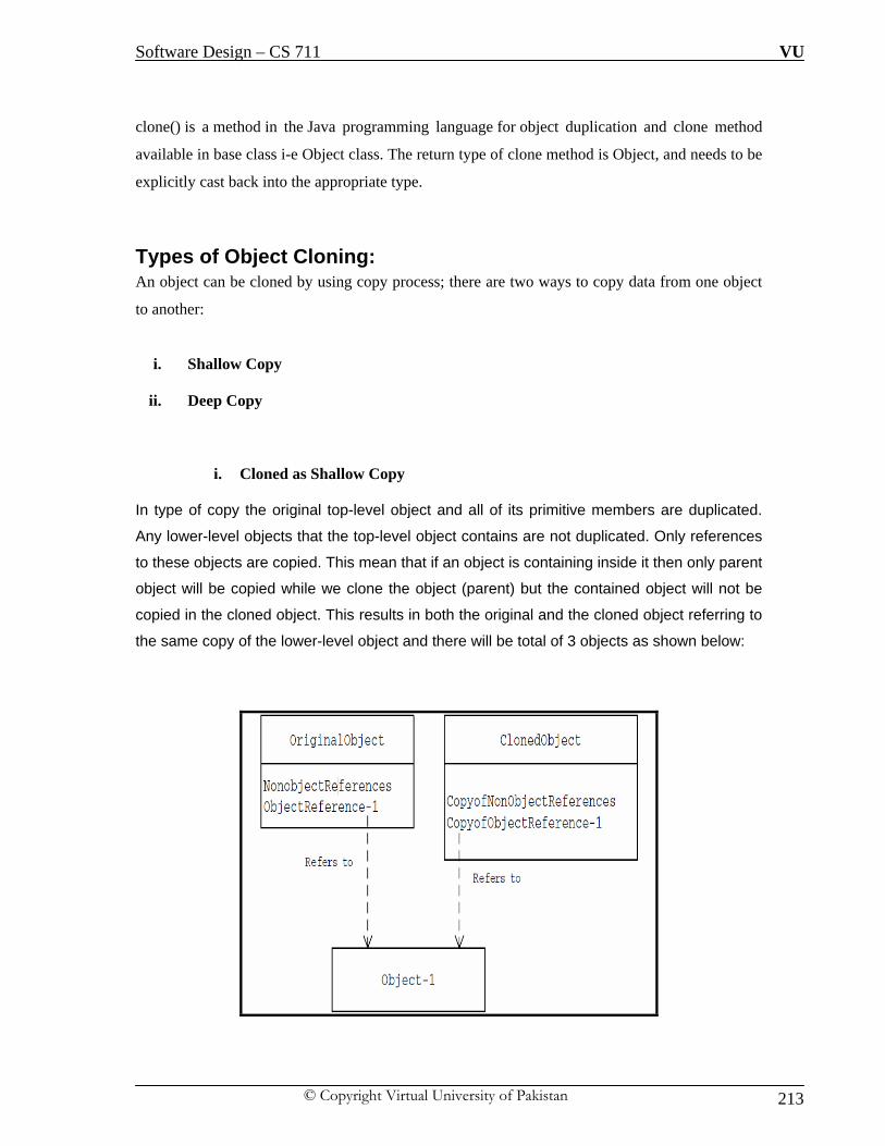
Software Design – CS 711 VU
© Copyright Virtual University of Pakistan 213
clone() is a method in the Java programming language for object duplication and clone method
available in base class i-e Object class. The return type of clone method is Object, and needs to be
explicitly cast back into the appropriate type.
Types of Object Cloning: An object can be cloned by using copy process; there are two ways to copy data from one object
to another:
i. Shallow Copy
ii. Deep Copy
i. Cloned as Shallow Copy
In type of copy the original top-level object and all of its primitive members are duplicated.
Any lower-level objects that the top-level object contains are not duplicated. Only references
to these objects are copied. This mean that if an object is containing inside it then only parent
object will be copied while we clone the object (parent) but the contained object will not be
copied in the cloned object. This results in both the original and the cloned object referring to
the same copy of the lower-level object and there will be total of 3 objects as shown below:

Software Design – CS 711 VU
© Copyright Virtual University of Pakistan 214
ii. Cloned as Deep Copy
In type of copy the original top-level object and all of its primitive members and any
lower-level objects that the top-level object contains are also duplicated. This mean that if
an object is containing inside it then only parent object will be copied while we clone the
object (parent) the contents of contained object will also be copied in the cloned object.
In this case, both the original and the cloned object refer to two different lower-level
objects i-e there will be total of 4 objects as compared to three objects in shallow copy.
This is shown in the diagram below:
Class Diagram:
The process of cloning starts with an initialized and instantiated class. The Client asks for a new
object of that type and sends the request to the Prototype class. A ConcretePrototype, depending

Software Design – CS 711 VU
© Copyright Virtual University of Pakistan 215
on the type of object is needed, will handle the cloning through the Clone () method, making a
new instance of itself.
Java Code of the above class diagram
public interface Prototype {
public abstract Object clone ( );
}
public class ConcretePrototype implements Prototype {
public Object clone() {
return super.clone();
}
}
public class Client {
public static void main( String arg[] )
{
ConcretePrototype obj1= new ConcretePrototype ();
ConcretePrototype obj2 = ConcretePrototype)obj1.clone();
}
}

Software Design – CS 711 VU
© Copyright Virtual University of Pakistan 216
Applicability:
We can use the prototype pattern when a system should be independent of how the products are
created, composed and represented; and
i. When the classes to instantiate are specified at run-time for example by using dynamic
loading.
ii. When heavy weight objects are required at number of occasions during the application.
Example
A computer user in a typical organization is associated with a user account. A user account can be
part of one or more groups. Permissions on different resources (such as servers, printers, etc.) are
defined at the group level. A user gets all the permissions defined for all groups that his or her
account is part of. Let us build an application to facilitate the creation of user accounts.
For simplicity, let us consider only two groups — Supervisor and AccountRep —
representing users who are supervisors and account representatives, respectively and we
have defined permissions in text files for each user group.
Proposed User Account Class:

Software Design – CS 711 VU
© Copyright Virtual University of Pakistan 217
Steps in Execution of Application:
i. Instantiate the UserAccount class
ii. Read permissions from an appropriate data file
iii. Set these permissions in the UserAccount object.
The above mention process looks straightforward, it is not efficient as it involves expensive file
I/O (input/output) each time an account is created. We need to optimize this to reduce the number
of I/O so that heavy weight object is not created for every account. This provide us
justification for using “Prototype Design Pattern”
Optimized Solution:
i. Re-Designing the UserAccount class to implement the Cloneable interface
ii. Returning a shallow copy of itself as part of its implementation of the clone method
Java Code of User Class using Cloneable Interface:
public class UserAccount implements Cloneable {
private String userName;
private String password;
private String fname;
private String lname;
private Vector permissions = new Vector();
public Object clone() {
//Shallow Copy
try {
return super.clone();
} catch (CloneNotSupportedException e) {

Software Design – CS 711 VU
© Copyright Virtual University of Pakistan 218
return null;}
Optimized Class Diagram:
Java Code for Optimized Class Diagram:
i. AccountPrototypeFactory Class
public class AccountPrototypeFactory {
private UserAccount accountRep;
private UserAccount supervisor;
public AccountPrototypeFactory(UserAccount supervisorAccount, UserAccount arep)
{
accountRep = arep;
supervisor = supervisorAccount;
}
public UserAccount getAccountRep() {
return (UserAccount) accountRep.clone();
}

Software Design – CS 711 VU
© Copyright Virtual University of Pakistan 219
public UserAccount getSupervisor() {
return (UserAccount) supervisor.clone();
}}
AccountManager Class:
public class AccountManager {
public static void main(String[] args) {
/*
Create Prototypical Objects
*/
Vector supervisorPermissions = getPermissionsFromFile("supervisor.txt");
UserAccount supervisor = new UserAccount();
supervisor.setPermissions(supervisorPermissions);
Vector accountRepPermissions = getPermissionsFromFile("accountrep.txt");
UserAccount accountRep = new UserAccount();
accountRep.setPermissions(accountRepPermissions);
AccountPrototypeFactory factory = new AccountPrototypeFactory(supervisor, AccountRep);
/* Using protype objects to create clones of user accounts */
UserAccount newSupervisor = factory.getSupervisor(); - Cloning is performed using existing
factory object
newSupervisor.setUserName("Ali");
newSupervisor.setPassword("canvas");
System.out.println(newSupervisor);
UserAccount anotherSupervisor = factory.getSupervisor();
anotherSupervisor.setUserName("Asim");
anotherSupervisor.setPassword("temp");
System.out.println(anotherSupervisor);
UserAccount newAccountRep = factory.getAccountRep();
newAccountRep.setUserName("Ahmad");
newAccountRep.setPassword("Pakistan");
System.out.println(newAccountRep);
}

Software Design – CS 711 VU
© Copyright Virtual University of Pakistan 220
LECTURE NO: 33
Objective: In this lecture we will discuss last design pattern of creational category, this design pattern is
builder design pattern. We will discuss this design pattern in detail with example.
Motivation: In broad spectrum object construction phase i-e details about components that make up an object
are kept within the object, often as part of its constructor and this is usual design and
programming practice. This type of design closely ties the object construction process with the
components that make up the object. This approach is well suited for the objects whose details are
simple but with the increase in complexity and number of components this approach is not suited
merely due to maintenance issues. This approach is suitable as long as the object under
construction is simple and the object construction process is definite and always produces the
same representation of the object. This design may not be effective when the object being created
is complex and the series of steps constituting the object creation process can be implemented in
different ways producing different representations of the object. Different implementations of the
construction process are all kept within the object, the object can become bulky (construction
bloat) and less modular. Subsequently, adding a new implementation or making changes to an
existing implementation requires changes to the existing code. Complex objects are made of parts
produced by other objects that need special care when being built. An application might need a
mechanism for building complex objects that is independent from the ones that make up the
object.
Intent of Builder Design Pattern
i. Defines an instance for creating an object but letting subclasses decide which class to
instantiate
ii. Refers to the newly created object through a common interface.
iii. Separate the construction of a complex object from its representation so that the same
construction process can create different representations.

Software Design – CS 711 VU
© Copyright Virtual University of Pakistan 221
Builder Design Pattern: To address the problem as discussed in previous section, the Builder pattern suggests moving the
construction logic out of the object class to a separate class referred to as a builder class. There
can be more than one such builder class each with different implementation for the series of steps
to construct the object. Each such builder implementation results in a different representation of
the object. This type of separation reduces the object size. The object construction process
becomes independent of the components that make up the object. This provides more control over
the object construction process. The suggested class diagram based on such a mechanism is
shown below:
Sequence Diagram of above Application

Software Design – CS 711 VU
© Copyright Virtual University of Pakistan 222
As shown in the sequence diagram, clients are initiating concrete objects which indirectly mean
that client should be aware of the object construction phase to create the complex objects. There is
tight coupling between client and object construction phase. Whenever the construction logic
undergoes a change, all client objects need to be modified accordingly. This implies that we are
making clients responsible to manage the object creation process which is certainly not wanted
and this is also a violation of design principles of loose coupling.
Builder Design Pattern: We need to solve the problem of tight coupling that exists in the suggested solution
between client and object, in solving this problem the Builder pattern suggests using a
dedicated object referred to as a Director, which is responsible for invoking different
builder methods required for the construction of the final object rather than client is
required to invoke the concrete objects directly. Different client objects can make use of
the Director object to create the required object and once the object is constructed, the
client object can directly request from the builder the fully constructed object.
Class Diagram An improved version or actual class diagram of builder design pattern is as shown below:

Software Design – CS 711 VU
© Copyright Virtual University of Pakistan 223
Application Flow: i. The client object creates instances of an appropriate concrete Builder implementer and
the Director. The client may use a factory for creating an appropriate Builder object.
ii. The client associates the Builder object with the Director object.
iii. The client invokes the build method on the Director instance to begin the object creation
process. Internally, the Director invokes different Builder methods required to construct
the final object.
iv. Once the object creation is completed, the client invokes the getObject method on the
concrete Builder instance to get the newly created object.
Sequence Diagram of Application: The sequence diagram is as per improved version of class diagram as shown above:

Software Design – CS 711 VU
© Copyright Virtual University of Pakistan 224
Example: Consider construction of a home, Home is the final end product (object) that is to be returned
as the output of the construction process. It will have many steps, like basement construction,
wall construction and so on roof construction. Finally the whole home object is returned. Here
using the same process you can build houses with different properties. Each house is having
same construction steps but the output may be different depending upon the requirements of
the house but the end product is home in any case. We need to write programs which simulate
this process.
Suggested Class Diagram:

Software Design – CS 711 VU
© Copyright Virtual University of Pakistan 225
Java Code:
i. House Plan Interface Class: package BuildingHouse;
public interface HousePlan {
public void setBasement(String basement);
public void setStructure(String structure);
public void setRoof(String roof);
public void setInterior(String interior);
}
ii. House Class:
package BuildingHouse;
public class House implements HousePlan {
private String basement;
private String structure;
private String roof;
private String interior;
public void setBasement(String basement) {
this.basement = basement;
}
public void setStructure(String structure) {
this.structure = structure;
}
public void setRoof(String roof) {

Software Design – CS 711 VU
© Copyright Virtual University of Pakistan 226
this.roof = roof;
}
public void setInterior(String interior) {
this.interior = interior;
}}
iii. HouseBuilder Interface Class
package BuildingHouse;
public interface HouseBuilder {
public void buildBasement();
public void buildStructure();
public void bulidRoof();
public void buildInterior();
public House getHouse();
}
iv. CivilEngineer Class
package BuildingHouse;
public class CivilEngineer {
private HouseBuilder houseBuilder;
public CivilEngineer(HouseBuilder houseBuilder){
this.houseBuilder = houseBuilder;
}

Software Design – CS 711 VU
© Copyright Virtual University of Pakistan 227
public House getHouse() {
return this.houseBuilder.getHouse();
}
public void constructHouse() {
this.houseBuilder.buildBasement();
this.houseBuilder.buildStructure();
this.houseBuilder.bulidRoof();
this.houseBuilder.buildInterior();
}}
v. IglooHouseBuilder Class:
package BuildingHouse;
public class IglooHouseBuilder implements HouseBuilder {
private House house;
public IglooHouseBuilder() {
this.house = new House();
}
public void buildBasement() {
house.setBasement("Ice Bars");
}
public void buildStructure() {
house.setStructure("Ice Blocks");
}
public void buildInterior() {
house.setInterior("Ice Carvings");
}
public void bulidRoof() {
house.setRoof("Ice Dome");

Software Design – CS 711 VU
© Copyright Virtual University of Pakistan 228
}
public House getHouse() {
return this.house;
}}
vi. BuilderSample (Main Program) package BuildingHouse;
public class BuilderSample {
public static void main(String[] args) {
HouseBuilder iglooBuilder = new IglooHouseBuilder();
CivilEngineer engineer = new CivilEngineer(iglooBuilder);
engineer.constructHouse();
House house = engineer.getHouse();
System.out.println("Builder constructed: "+house);
}
}

Software Design – CS 711 VU
© Copyright Virtual University of Pakistan 229
Comparison of Design Pattern of Creational Category: Below is the chart which provides comparison of the design pattern discussed of creational
category by comparing them in term of need for application, client knowledge and advantages
/disadvantages.

Software Design – CS 711 VU
© Copyright Virtual University of Pakistan 230
LECTURE NO: 34
Objective: In this lecture we will structural category of design pattern and will discuss adapter design pattern
of structural category in detail with example.
Structural Design Pattern: This category of design pattern deals with how classes and objects deal with to form large
structures. Structural Design patterns use inheritance to compose interfaces or implementations to
form the structure of larger systems. Structural Design Patterns basically ease the design by
identifying the relationships between entities. Object-oriented patterns describe ways to compose
objects to realize new functionality, possibly by changing the composition at run-time. Deal with
objects delegating responsibilities to other objects. This behavior results in a layered architecture
of components with low degree of coupling. They facilitate interobject communication when one
object is not accessible to the other by normal means or when an object is not usable because of
its incompatible interface.
Adapter or Wrapper Design Pattern: Motivation:
The adapter pattern is adapting between classes and objects. Like any adapter in the real world it
is used to be an interface, a bridge between two objects. In real world we have adapters for power
supplies, adapters for camera memory cards, and so on. Probably everyone has seen some
adapters for memory cards. If you cannot plug in the camera memory in your laptop you can use
and adapter. You plug the camera memory in the adapter and the adapter in to laptop slot. That's
it, it's really simple. What about software development? It's the same. Just imagine a situation
when you have some class expecting some type of object and you have an object offering the
same features, but exposing a different interface? Of course, you want to use both of them so you
don't to implement again one of them, and you don't want to change existing classes, so why not
create an adapter class for accessing the features. This could happen due to various reasons such
as the existing interface may be too detailed, or it may lack in detail, or the terminology used by
the interface may be different from what the client is looking for. The adapter is also responsible
for transforming data into appropriate forms. For instance, if multiple boolean values are stored as

Software Design – CS 711 VU
© Copyright Virtual University of Pakistan 231
a single integer (i.e. flags) but your consumer requires a 'true'/'false', the adapter would be
responsible for extracting the appropriate values from the integer value. Another example is
transforming the format of dates (e.g. YYYYMMDD to MM/DD/YYYY or DD/MM/YYYY).
Intent:
i. Convert the interface of a class into another interface clients expect.
ii. Adapter lets classes work together, that could not otherwise because of incompatible
interfaces
iii. Keeping the client code intact we need to write a new class which will make use of
services offered by the class.
Adapter Pattern Defined:
“Adapter pattern convert the interface of the class into a form what client expects.
Adapter let the classes work together which couldn’t otherwise due to incompatible
interfaces.”
Applicability:
i. We want to use the existing class and its interface does not match with the one you need.
ii. In case of reusable classes due to Non-Compatible interfaces it is not possible to reuse
them.
Class Diagram:

Software Design – CS 711 VU
© Copyright Virtual University of Pakistan 232
The classes/objects participating in adapter pattern:
i. Target - defines the domain-specific interface that Client uses. This class is visible to the
client and client will interact or pass request to this class. ii. Adapter - adapts the interface Adaptee to the Target interface.
iii. Adaptee - defines an existing interface that needs adapting.
iv. Client - collaborates with objects conforming to the Target interface.
Object Adapter:
Objects Adapters (discussed so far) are the classical example of the adapter pattern. It
uses composition; the Adaptee delegates the calls to Adaptee (opposed to class adapters
which extends the Adaptee). This behavior gives us a few advantages over the class
adapters (however the class adapters can be implemented in languages allowing multiple
inheritances). The main advantage is that the Adapter adapts not only the Adaptee but all
its subclasses. All it's subclasses with one "small" restriction: all the subclasses which
don't add new methods, because the used mechanism is delegation. So for any new
method the Adapter must be changed or extended to expose the new methods as well. The
main disadvantage is that it requires writing all the code for delegating all the necessary
requests to the Adaptee.
Class Adapters - Based on (Multiple) Inheritance

Software Design – CS 711 VU
© Copyright Virtual University of Pakistan 233
Class adapters can be implemented in languages supporting multiple inheritance (Java,
C# or PHP does not support multiple inheritance). Thus, such adapters cannot be easy
implemented in Java, C# or VB.NET.
Class adapter uses inheritance instead of composition. It means that instead of delegating
the calls to the Adaptee, it subclasses it. In conclusion it must subclass both the Target
and the Adaptee.

Software Design – CS 711 VU
© Copyright Virtual University of Pakistan 234
Class Diagram of Class Adapters:
Advantages / Disadvantages of Class Adapters:
i. It adapts the specific Adaptee class. The class it extends. If that one is subclassed it
cannot be adapted by the existing adapter.
ii. It doesn't require all the code required for delegation, which must be written for an Object
Adapter.
If the Target is represented by an interface instead of a class then we can talk about "class"
adapters, because we can implement as many interfaces as we want.
How Much to Adapt:
This question has a really simple response: it should do how much it has to in order to adapt. It's
very simple, if the Target and Adaptee are similar then the adapter has just to delegate the
requests from the Target to the Adaptee. If Target and Adaptee are not similar, then the adapter
might have to convert the data structures between those and to implement the operations required
by the Target but not implemented by the Adaptee.

Software Design – CS 711 VU
© Copyright Virtual University of Pakistan 235

Software Design – CS 711 VU
© Copyright Virtual University of Pakistan 236

Software Design – CS 711 VU
© Copyright Virtual University of Pakistan 237
LECTURE NO: 35
Objective: In this lecture we will structural category of design pattern and will discuss facade design pattern
of structural category in detail with example.
Façade Design Pattern Motivation: In real world applications, a subsystem could consist of a large number of classes. Clients of a
subsystem may need to interact with a number of subsystem classes for their needs. This kind of
direct interaction of clients with subsystem classes leads to a high degree of coupling between the
client objects and the subsystem. Whenever a subsystem class undergoes a change, such as a
change in its interface, all of its dependent client classes may get affected. A subsystem is a set of
classes that work in conjunction with each other for the purpose of providing a set of related
features (functionality). For example, an Account class, Address class and CreditCard class
working together, as part of a subsystem, provide features of an online customer.
Intent: i. To provide a simple interface to use the complex sub systems to the users by keeping
intact the functionality of subsystems
ii. Power of subsystems will still be there but there will simplified access to the underlying
subsystems.
Façade Pattern Defined:
“Façade provides a unified interface to a set of interfaces in a
subsystem. It define a higher level interface which is easier to use”

Software Design – CS 711 VU
© Copyright Virtual University of Pakistan 238
Façade decouple the client from interacting with the subsystems instead Façade take up the
responsibility of dealing with the subsystems itself. In effect, clients interface with the façade to
deal with the subsystem. Thus the Façade pattern promotes a weak coupling between a subsystem
and its clients Façade will not add any extra functionality it will just simply the access to
functionality. Client can also access subsystems directly as if there is no Façade.
Following figures provide a graphical comparison of system access without and with facade
Client Access without Façade:
As shown below in the absence of façade, multiple clients are dealing with different classes that
mean clients are aware of logic to interact with the underlying classes’ i-e high coupling; which
is not wanted or minimal coupling should be there between client and underlying system but the
given scenario violate that rule. In such a scenario the responsibility of success of system is
dependent heavily as to how client deal the underlying system.

Software Design – CS 711 VU
© Copyright Virtual University of Pakistan 239
Client Access with Façade: As shown in the figure below, can see that the Façade object decouples and shields clients from
subsystem objects. When a subsystem class undergoes a change, clients do not get affected as
before. Even though clients use the simplified interface provided by the façade, when needed, a
client will be able to access subsystem components directly through the lower level interfaces of
the subsystem as if the Façade object does not exist. In this case, they will still have the same
dependency/coupling issue as earlier.

Software Design – CS 711 VU
© Copyright Virtual University of Pakistan 240
Class Diagram:
The Principle of Least Knowledge (PLK)
“Talk only to your immediate friends”
OR
“For an operation O on a class C, only operations on the following objects should
be called: itself, its parameters, objects it creates, or its contained instance objects”
The basic idea is to avoid calling any methods on an object where the reference to that object is
obtained by calling a method on another object. Instead, this principle recommends we call
methods on the containing object, not to obtain a reference to some other object, but instead to
allow the containing object to forward the request to the object we would have formerly obtained
a reference to. The primary benefit is that the calling method doesn’t need to understand the
structural makeup of the object its invoking methods upon. When creating software design for any
object should be careful of the number of classes it is interacting with and how it will be
interacting with them. With increase in number of classes it interacting reflects the complexity
and mechanism to interact with classes reflect communication overhead which underlying is
currently performing. This principle prevents us from creating designs that have a large number of

Software Design – CS 711 VU
© Copyright Virtual University of Pakistan 241
classes coupled together. When you build a lot of dependencies between many classes, you are
building a system that will be costly to maintain and complex for others to understand.
Guidelines to Implement PLK:
Suppose we have an object with several methods, now for that object we should invoke methods
only that belong to:
i. An Object itself
ii. Object passed in as a parameter
iii. Any method that object creates or instantiates.
iv. Any component of the Object
Example of PLK:

Software Design – CS 711 VU
© Copyright Virtual University of Pakistan 242
Principle of Least Knowledge and Façade:
When we apply PLK to façade design pattern then it emerge that it is not rule of the thumb that
there should be only one façade within a system. There can be several Façade within One Façade
with the increase in complexity. We aim to maintain minimum possible communication with
other classes but this does not stop us from defining multi-level façade or façade within façade to
provide unified and simplified access to client of the underlying system.

Software Design – CS 711 VU
© Copyright Virtual University of Pakistan 243
Problem Statement:
For a typical online transaction oriented system, customer can perform transactions
against an account i-e Pay pal etc; credit card validators are used for verifying the
creditionals of a client submitted by the client for checkout purposes. Address of the
customer is also stored and checked for data entry checks for shipment purposes. Usually
account, address and credit card subsystems works together to provide the feature of
online transaction.
To Do Task:
Build an application using façade design pattern which perform the following tasks
i. Accepts customer details (account, address and credit card details)
ii. Validates the input data
iii. Saves the input data to appropriate data files
Assuming there are three classes and each class is having its own validation and data storage
mechanism
Sequence Diagram of the Problem Statement with Facade:

Software Design – CS 711 VU
© Copyright Virtual University of Pakistan 244
LECTURE NO: 36
Objective: In this lecture we will structural category of design pattern and will discuss composite design
pattern of structural category in detail with example.
Composite Design Pattern: Motivation This design pattern has a resemblance with concept of recursion or tree structure in data structures
where every component is either a leaf node or composed of other nodes to make its next level.
There are times when a program needs to manipulate a tree data structure and it is necessary to
treat both Branches as well as Leaf Nodes uniformly.
Consider for example a program that manipulates a file system. A file system is a tree structure
that contains Branches which are Folders as well as Leaf nodes which are Files. Note that a folder
object usually contains one or more file or folder objects and thus is a complex object where a file
is a simple object. Note also that since files and folders have many operations and attributes in
common, such as moving and copying a file or a folder, listing file or folder attributes such as file
name and size, it would be easier and more convenient to treat both file and folder objects
uniformly by defining a File System Resource Interface. So the essence is that at times
components are build using other components, we can classify component or object in one of the
two categories —
i. Individual Components – Leaf Node
ii. Composite Components — which are composed of individual components or other
composite components – Child Node(s)

Software Design – CS 711 VU
© Copyright Virtual University of Pakistan 245
Intent
i. The intent of this pattern is to compose objects into tree structures to represent part-whole
hierarchies’ i-e Aggregation.
ii. Composite lets clients treat individual objects and compositions of objects uniformly.
Here it would be pertinent that we can revisit the concept of tree structure of data structure as this
design pattern deals with tree structure.
Tree Structure Revisited: Tree is a data structure where there is a root, child and leaf nodes. There is only one root node in a
tree, multiple child and leaf nodes. Child can have further nodes but leaf cannot have further
nodes. Trees are a special case of a graph data structure. The connections radiate out from a single
root without cross connections. The tree has nodes (shown with circles) that are connected with
branches. Each node will have a parent node (except for the root) and may have multiple child
nodes as shown below: Node A is a root node, b and C are child nodes, D,E and F are leaf nodes
because they are having no further child nodes.

Software Design – CS 711 VU
© Copyright Virtual University of Pakistan 246
Composite Pattern Defined:
“Composite Design pattern allow us to compose objects into tree structures
to represent whole-part hierarchy. It let the client handle the composite and
individual components in a uniform manner”
Class Diagram:
Description of Class Diagram and Application Flow:
i. Component - Component is the abstraction for leafs and composites. It defines the
interface that must be implemented by the objects in the composition. For example a file
system resource defines move, copy, rename, and getSize methods for files and folders.
ii. Leaf - Leafs are objects that have no children. They implement services described by the
Component interface. For example a file object implements move, copy, rename, as well
as getSize methods which are related to the Component interface.
iii. Composite - A Composite stores child components in addition to implementing methods
defined by the component interface. Composites implement methods defined in the
Component interface by delegating to child components. In addition composites provide
additional methods for adding, removing, as well as getting components.

Software Design – CS 711 VU
© Copyright Virtual University of Pakistan 247
iv. Client - The client manipulates objects in the hierarchy using the component interface.
A client has a reference to a tree data structure and needs to perform operations on all nodes
independent of the fact that a node might be a branch or a leaf. The client simply obtains
reference to the required node using the component interface, and deals with the node using this
interface; it doesn’t matter if the node is a composite or a leaf.
Applicability
The composite pattern applies when there is a part-whole hierarchy of objects and a client needs
to deal with objects uniformly regardless of the fact that an object might be a leaf or a branch.
Vectors in Java:
It is relevant to discuss vectors in java as we will be using this concept in the example. Vectors
(the java.util.Vector class) are commonly used instead of arrays, because they expand
automatically when new data is added to them.Vectors can hold only Objects and not
primitive types (eg, int). If you want to put a primitive type in a Vector, put it inside an
object (eg, to save an integer value use the Integer class or define your own class). If you
use the Integer wrapper, you will not be able to change the integer value, so it is
sometimes useful to define your own class. Vectors are implemented with an array, and when
that array is full and an additional element is added, a new array must be allocated. Because it
takes time to create a bigger array and copy the elements from the old array to the new array, it is
a little faster to create a Vector with a size that it will commonly be when full. Of course, if you
knew the final size, you could simply use an array. However, for non-critical sections of code
programmers typically don't specify an initial size.
i. Create a Vector with default initial size
Vector v = new Vector();
ii. Create a Vector with an initial size
Vector v = new Vector(300);
iii. To Add elements to the end of a Vector:
v.add(s);

Software Design – CS 711 VU
© Copyright Virtual University of Pakistan 248
iv. To get element from a Vector:
You can use a for loop to get all the elements from a Vector, but another very common
way to go over all elements in a Vector is to use a ListIterator. The advantage of an
iterator is that it it can be used with other data structures, so that if you later change to
using another data structure for example linkedlist, you won't have to change your code.
Here is an example of using an iterator to print all elements (Strings) in a vector. The two
most useful methods are hasNext(), which returns true if there are more elements,
and next(), which returns the next element.
ListIterator iter = v.listIterator();
While(iter.hasnext())
{
System.out.println((String)iter.next());
}

Software Design – CS 711 VU
© Copyright Virtual University of Pakistan 249
Example with Code
Let us create an application to simulate the Windows/UNIX file system. The file system
consists mainly of two types of components — directories and files. Directories can be
made up of other directories or files, whereas files cannot contain any other file system
component. In this aspect, directories act as nonterminal nodes and files act as terminal
nodes or leaf node of a tree structure. The client will be able to calculate the size of file or
folder irrespective of the internal representation of the storage mechanism.
Design Approach –I
Let us define a common interface for both directories and files in the form of a Java
interface FileSystemComponent. The FileSystemComponent interface declares methods
that are common for both file components and directory components. Let us further
define two classes — FileComponent and DirComponent — as implementers of the
common FileSystemComponent interface as shown:

Software Design – CS 711 VU
© Copyright Virtual University of Pakistan 250
Processing of Class Diagram
A typical client would first create a set of FileSystemComponent objects (both
DirComponent and FileComponent instances). It can use the addComponent method of
the DirComponent to add different FileSystemComponents to a DirComponent, creating
a hierarchy of file system (FileSystemComponent) objects.
Problem in current Approach: When the client wants to query any of these objects for its size, it can simply invoke the
getComponentSize method. The client does not have to be aware of the calculations
involved or the manner in which the calculations are carried out in determining the
component size. In this aspect, the client treats both the FileComponent and the
DirComponent object in the same manner. No separate code is required to query
FileComponent objects and DirComponent objects for their size. Though the client treats
both the FileComponent and DirComponent objects in a uniform manner in the case of
the common getComponentSize method, it does need to distinguish when calling
composite specific methods such as addComponent and getComponent defined
exclusively in the DirComponent. Because these methods are not available with
FileComponent objects, the client needs to check to make sure that the
FileSystemComponent object it is working with is in fact a DirComponent object.
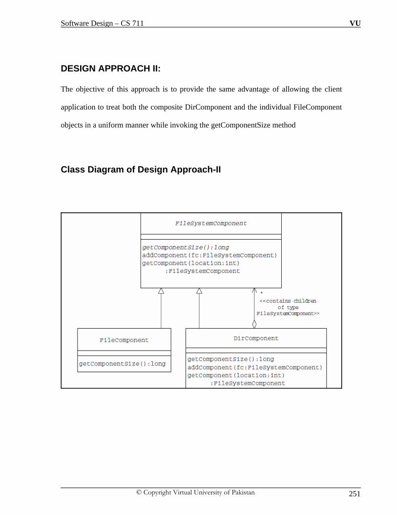
Software Design – CS 711 VU
© Copyright Virtual University of Pakistan 251
DESIGN APPROACH II: The objective of this approach is to provide the same advantage of allowing the client
application to treat both the composite DirComponent and the individual FileComponent
objects in a uniform manner while invoking the getComponentSize method
Class Diagram of Design Approach-II

Software Design – CS 711 VU
© Copyright Virtual University of Pakistan 252
Design Approach –II Explained:
In the new design the composite-specific addComponent and getComponent methods are
moved to the common interface FileSystem- Component. The FileSystemComponent
provides the default implementation for these methods and is designed as an abstract
class.
The default implementation of these methods consists of what is applicable to
FileComponent objects. FileComponent objects are individual objects and do not contain
other FileSystemComponent objects within. Hence, the default implementation does
nothing and simply throws a custom CompositeException exception. The derived
composite DirComponent class overrides these methods to provide custom
implementation because there is no change in the way the common getComponentSize
method is designed; the client will still be able to treat both the composite DirComponent
and FileComponent objects identically. Because the common parent
FileSystemComponent class now contains default implementations for the
addComponent and the getComponent methods, the client application does not need to
make any check before making a call to these composite-specific methods.

Software Design – CS 711 VU
© Copyright Virtual University of Pakistan 253
Java Code of the Example package composite;
public abstract class FileSystemComponent {
String name;
public FileSystemComponent(String cName) {
name = cName;
}
public void addComponent(FileSystemComponent component)
throws CompositeException {
throw new CompositeException("Invalid Operation. Not Supported");
}
public FileSystemComponent getComponent(int componentNum)
throws CompositeException {
throw new CompositeException("Invalid Operation. Not Supported");
}
public abstract long getComponentSize();
}//End of class FileSystemComponent

Software Design – CS 711 VU
© Copyright Virtual University of Pakistan 254
package composite;
public class FileComponent extends FileSystemComponent
{
private long size;
public FileComponent(String cName, long sz)
{
super(cName);
size = sz;
}
public long getComponentSize()
{
return size;
}
}//End of class

Software Design – CS 711 VU
© Copyright Virtual University of Pakistan 255
package composite;
import java.util.Vector;
public class DirComponent extends FileSystemComponent
{
Vector dirContents = new Vector();
//individual files/sub folders collection
public DirComponent(String cName)
{
super(cName);
}
public void addComponent(FileSystemComponent fc)
throws CompositeException
{
dirContents.add(fc);
}
public FileSystemComponent getComponent(int location)
throws CompositeException {
return (FileSystemComponent) dirContents.elementAt(location);
}
public long getComponentSize()
{
long sizeOfAllFiles = 0;
Enumeration e = dirContents.elements();
while (e.hasMoreElements()) {
FileSystemComponent component = (FileSystemComponent) e.nextElement();
sizeOfAllFiles = sizeOfAllFiles + (component.getComponentSize());
}
return sizeOfAllFiles;
}
}//End of class

Software Design – CS 711 VU
© Copyright Virtual University of Pakistan 256
Sample File Structure Used in the Main Program
package composite;
public class CompositeDemo
{
public static final String SEPARATOR = ”, ";
public static void main(String[] args) {
FileSystemComponent mainFolder = new DirComponent("Year2000");
FileSystemComponent subFolder1 = new DirComponent("Jan");
FileSystemComponent subFolder2 = new DirComponent("Feb");
//creating files
FileSystemComponent folder1File1 = new FileComponent("Jan1DataFile.txt,”1000);
FileSystemComponent folder1File2 = new FileComponent("Jan2DataFile.txt”,2000);
FileSystemComponent folder2File1 = new FileComponent("Feb1DataFile.txt”,3000);
FileSystemComponent folder2File2 = new FileComponent("Feb2DataFile.txt”,4000);
try {
mainFolder.addComponent(subFolder1);

Software Design – CS 711 VU
© Copyright Virtual University of Pakistan 257
mainFolder.addComponent(subFolder2);
subFolder1.addComponent(folder1File1);
subFolder1.addComponent(folder1File2);
subFolder2.addComponent(folder2File1);
subFolder2.addComponent(folder2File2);
} catch (CompositeException ex) {
//
}
//Client refers to both composite & //individual components in a uniform manner
System.out.println (" Main Folder Size= " + mainFolder.getComponentSize() + "kb");
System.out.println(" Sub Folder1 Size= " + subFolder1.getComponentSize() + "kb");
System.out.println(" File1 in Folder1 size= " + folder1File1.getComponentSize() + "kb");
}
}

Software Design – CS 711 VU
© Copyright Virtual University of Pakistan 258
LECTURE NO: 37
Objective: In this lecture we will discuss Flyweight design pattern of the creational category of design
pattern in detail with example.
Flyweight Design Pattern: Motivation There are cases when we design a system and program, where it seems that there is a need to
generate a very large number of small class instances to represent data. Sometimes you can
greatly reduce the number of different classes that you need to instantiate if you can recognize
that the instances are fundamentally the same except for a few parameters. If you can move those
variables outside the class instance and pass them in as part of a method call, the number of
separate instances can be greatly reduced.
Generally speaking we can say that there are situations where there is a possibility of sharing the
data among instances of classes but merely due to our overlooking of the commonality we define
large number of classes to represent the similar data, so the essence is to focus more on sharing
the data rather than creating more classes because as we define new classes the issue of
maintaining these classes will require great effort. Every object can be viewed as consisting of
one or both of the following two sets of information:
i. Intrinsic Information or Shareable information:
The intrinsic information of an object is independent of the object context. That means the
intrinsic information is the common information that remains constant among different instances
of a given class. For example, the company information on a visiting card is the same for all
employees.
ii. Extrinsic Information or Variant or Non-Shareable:
The extrinsic information of an object is dependent upon and varies with the object context. That
means the extrinsic information is unique for every instance of a given class. For example, the

Software Design – CS 711 VU
© Copyright Virtual University of Pakistan 259
employee name and title are extrinsic on a visiting card as this information is unique for every
employee.
Consider an application scenario that involves creating a large number of objects that are unique
only in terms of a few parameters. In other words, these objects contain some intrinsic, invariant
data that is common among all objects. This intrinsic data needs to be created and maintained as
part of every object that is being created. The overall creation and maintenance of a large group of
such objects can be very expensive in terms of memory-usage and performance, in other words
we are creating a heavyweight application with maintenance overhead. For example, if you are
drawing a series of icons on the screen in a folder window, where each represents a person or data
file, it does not make sense to have an individual class instance for each of them that remembers
the person’s name and the icon’s screen position. Typically these icons are one of a few similar
images and the position where they are drawn is calculated dynamically based on the window’s
size in any case.
Intent of Flyweight Design Pattern:
i. To use sharing to support a large number of objects that have part of their internal state in
common where the other part of state can vary.
Factory Pattern Defined:
“Facilitates the reuse of many fine grained objects, making the utilization of
large numbers of objects more efficient”
Suggested Approach: The Flyweight pattern suggests separating all the intrinsic common data into a separate object
referred to as a Flyweight object. The group of objects being created can share the
Flyweight object as it represents their intrinsic state. This eliminates the need for storing the
same invariant, intrinsic information in every object; instead it is stored only once in the form of a
single Flyweight object. As a result, the client application can realize considerable savings in
terms of the memory-usage and the time.

Software Design – CS 711 VU
© Copyright Virtual University of Pakistan 260
Class Diagram:
Description of Classes:
i. Flyweight - Declares an interface through which flyweights can receive and act on
extrinsic state.
ii. Concrete Flyweight - Implements the Flyweight interface and stores intrinsic state. A
Concrete Flyweight object must be sharable. The Concrete flyweight object must
maintain state that it is intrinsic to it, and must be able to manipulate state that is extrinsic.
iii. Flyweight Factory - The factory creates and manages flyweight objects. In addition the
factory ensures sharing of the flyweight objects. The factory maintains a pool of different
flyweight objects and returns an object from the pool if it is already created, adds one to
the pool and returns it in case it is new.
iv. Client - A client maintains references to flyweights in addition to computing and
maintaining extrinsic state

Software Design – CS 711 VU
© Copyright Virtual University of Pakistan 261
Flow of Application using Flyweight Design Pattern: Flyweights are sharable instances of a class. It might at first seem that each class is a Singleton,
but in fact there might be a small number of instances, such as one for every character, or one for
every icon type. The number of instances that are allocated must be decided as the class instances
are needed, and this is usually accomplished with a Flyweight Factory class. This factory class
usually is a Singleton, since it needs to keep track of whether or not a particular instance has been
generated yet. It then either returns a new instance or a reference to one it has already generated.
A client needs a flyweight object; it calls the factory to get the flyweight object. The factory
checks a pool of flyweights to determine if a flyweight object of the requested type is in the pool,
if there is, the reference to that object is returned. If there is no object of the required type, the
factory creates a flyweight of the requested type, adds it to the pool, and returns a reference to the
flyweight. The flyweight maintains intrinsic state (state that is shared among the large number of
objects that we have created the flyweight for) and provides methods to manipulate external state
(State that vary from object to object and is not common among the objects we have created the
flyweight for).
Factory and Singleton patterns:
Flyweights are usually created using a factory and the singleton is applied to that factory so that
for each type or category of flyweights a single instance is returned.

Software Design – CS 711 VU
© Copyright Virtual University of Pakistan 262
Example: We need to design for a war game in which there is a large number of soldier objects; a soldier
object maintain the graphical representation of a soldier, soldier behavior such as motion, and
firing weapons, in addition soldiers health and location on the war terrain. Creating a large
number of soldier objects is a necessity however it would incur a huge memory cost.
Note that although the representation and behavior of a soldier is the same their health and
location can vary greatly. The war game instantiates 5 Soldier clients, each client maintains
its internal state which is extrinsic to the soldier flyweight, although 5 clients have been
instantiated only one flyweight Soldier has been used.
Proposed Class Diagram

Software Design – CS 711 VU
© Copyright Virtual University of Pakistan 263
Java Code:
i. Soldier Interface
package flyweight;
/** * Flyweight Interface * */
public interface Soldier
{
/**
Move Soldier From Old Location to New Location Note that soldier location is extrinsic to the
SoldierFlyweight Implementation */
public void moveSoldier(int previousLocationX, int previousLocationY , int newLocationX
,int newLocationY);
}

Software Design – CS 711 VU
© Copyright Virtual University of Pakistan 264
ii. SoldierImp class
package flyweight;
public class SoldierImp implements Soldier {
/**
*Intrinsic State maintained by flyweight implementation
* Solider Shape ( graphical represetation)
* how to display the soldier is up to the flyweight implementation
*/
private Object soldierGraphicalRepresentation;
/**
* Note that this method accepts soldier location
* Soldier Location is Extrinsic and no reference to previous location
* or new location is maintained inside the flyweight implementation
*/
public void moveSoldier(int previousLocationX, int previousLocationY,int newLocationX,
int newLocationY)
{
// delete soldier representation from previous location
// then render soldier representation in new location
}
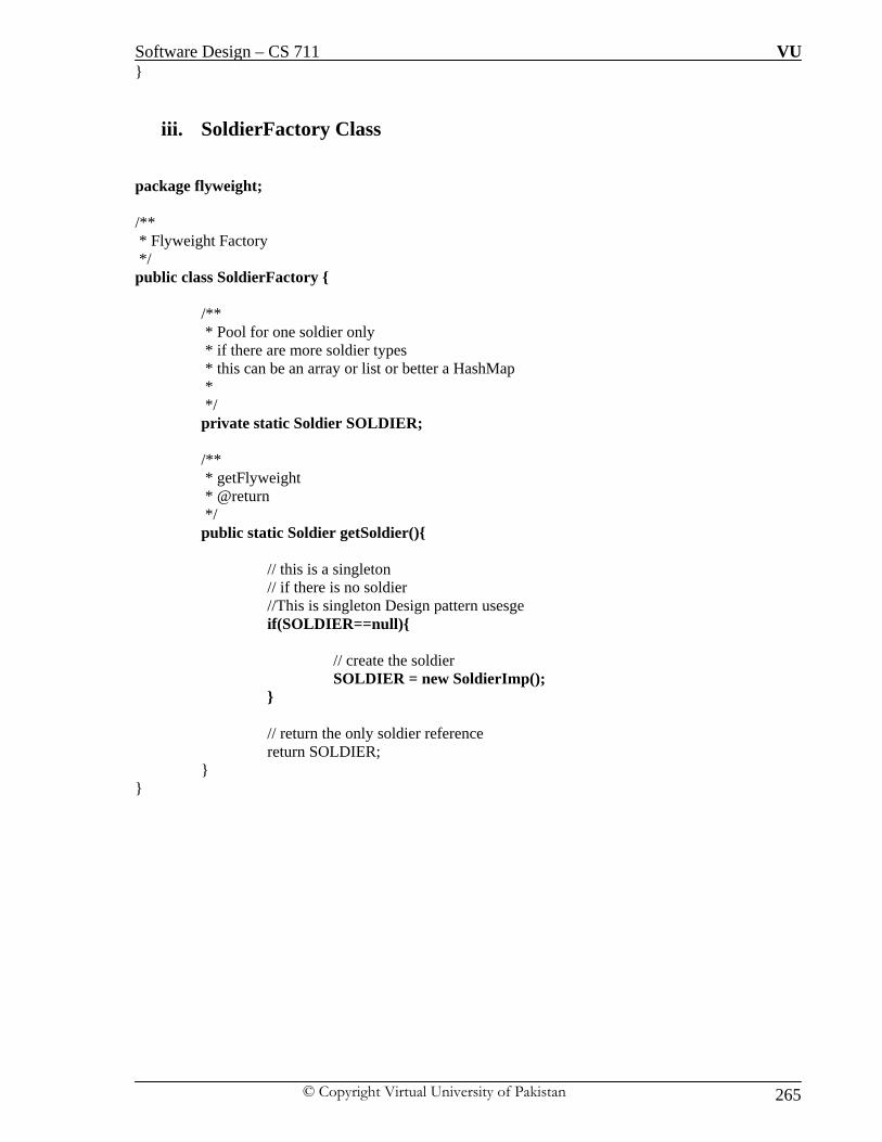
Software Design – CS 711 VU
© Copyright Virtual University of Pakistan 265
}
iii. SoldierFactory Class
package flyweight; /** * Flyweight Factory */ public class SoldierFactory { /** * Pool for one soldier only * if there are more soldier types * this can be an array or list or better a HashMap * */ private static Soldier SOLDIER; /** * getFlyweight * @return */ public static Soldier getSoldier(){ // this is a singleton // if there is no soldier //This is singleton Design pattern usesge if(SOLDIER==null){ // create the soldier SOLDIER = new SoldierImp(); } // return the only soldier reference return SOLDIER; } }

Software Design – CS 711 VU
© Copyright Virtual University of Pakistan 266
iv. SoldierClient Class package flyweight;
/**
* This is the "Heavyweight" soldier object which is the client of the flyweight soldier this object
provides all soldier services and is used in the game */
public class SoldierClient {
/**
* Reference to the flyweight
*/
private Soldier soldier = SoldierFactory.getSoldier();
/**
* this state is maintained by the client
*/
private int currentLocationX = 0;
/**
* this state is maintained by the client
*/
private int currentLocationY=0;
public void moveSoldier(int newLocationX, int newLocationY)
{
// here the actual rendering is handled by the flyweight object
// this object is responsible for maintaining the state
// that is extrinsic to the flyweight
soldier.moveSoldier(currentLocationX, currentLocationY, newLocationX, newLocationY);
currentLocationX = newLocationX;
currentLocationY = newLocationY;

Software Design – CS 711 VU
© Copyright Virtual University of Pakistan 267
}}

Software Design – CS 711 VU
© Copyright Virtual University of Pakistan 268
v. WarGame – Main class package flyweight;
/**
* Driver : War Game
*/
public class WarGame {
public static void main(String[] args)
{
// start war
// draw war terrain
// create 5 soldiers:
SoldierClient warSoldiers [] ={new SoldierClient(),new SoldierClient(),
new SoldierClient(),
new SoldierClient(),
new SoldierClient()
};
// move each soldier to his location
// take user input to move each soldier
warSoldiers[0].moveSoldier(17, 2112);
// take user input to move each soldier
warSoldiers[1].moveSoldier(137, 112);
// note that there is only one SoldierImp (flyweight Imp)
// for all the 5 soldiers
// Soldier Client size is small due to the small state it maintains
// SoliderImp size might be large or might be small
// however we saved memory costs of creating 5 Soldier representations
}
}

Software Design – CS 711 VU
© Copyright Virtual University of Pakistan 269
LECTURE NO: 38
Objective: In this lecture we will discuss proxy design pattern of structural category in detail with example.
We will also have an overview of RMI in relationship with proxy design pattern.
Proxy or Surrogate Design Pattern: Motivation As a name suggest, it is not the actual class to whom the client think it is dealing rather it is
artificial class acting like original class for the client. Generally speaking a proxy is a person
authorized to act for another person an agent or substitute the authority to act for another. There
are situations in which a client does not or cannot reference an object directly, but wants to still
interact with the object. A proxy object can act as the intermediary between the client and the
target object. The proxy object has the same interface as the target object; it holds a reference to
the target object and can forward requests to the target as required (delegation!).
In effect, the proxy object has the authority the act on behalf of the client to interact with the
target object.
Sometimes we need the ability to control the access to an object. For example if we need to use
only a few methods of some costly objects we'll initialize those objects when we need them
entirely. Until that point we can use some light objects exposing the same interface as the heavy
objects. These light objects are called proxies and they will instantiate those heavy objects when
they are really need and by then we'll use some light objects instead. This ability to control the
access to an object can be required for a variety of reasons: controlling when a costly object needs
to be instantiated and initialized, giving different access rights to an object, as well as providing a
sophisticated means of accessing and referencing objects running in other processes, on other
machines.
Type of Proxies:
i. Virtual Proxies: delaying the creation and initialization of expensive objects until
needed, where the objects are created on demand
ii. Remote Proxies: providing a local representation for an object that is in a different
address space. A common example is Java RMI stub objects. The stub object acts as a

Software Design – CS 711 VU
© Copyright Virtual University of Pakistan 270
proxy where invoking methods on the stub would cause the stub to communicate and
invoke methods on a remote object (called skeleton) found on a different machine
iii. Protection Proxies: where a proxy controls access to original object, by giving access
to some objects while denying access to others.
iv. Smart References: providing a sophisticated access to certain objects such as tracking
the number of references to an object and denying access if a certain number is reached,
as well as loading an object from database into memory on demand.
Remote Method Innovation (RMI)
We will discuss the concept of RMI from view point of remote proxies. RMI is used when object
of a class wants to access the method of another class but the other class is on the remote machine
and to access the remote machine certain mechanism and protocol is to be followed. RMI
basically highlight the protocol which govern the communication between object two remote
machines. RMI is a multiple step communication protocol in which classes must implement
certain interfaces to enable remote communication. Below are the classes along with its
description:
Remote Interface — A remote object must implement a remote interface (one that extends
java.rmi.Remote). A remote interface declares the methods in the remote object that can be
accessed by its clients. In other words, the remote interface can be seen as the client’s view of the
remote object.
Remote Object — A remote object is responsible for implementing the methods declared in the
associated remote interface.
RMI Registry — RMI registry provides the storage area for holding different remote objects. It
is directory of remote objects with reference name which client can access
Client — Client is an application object attempting to use the remote object.
– Can search for a remote object using a name reference in the RMI
Registry. Once the remote object reference is found, it can invoke methods on this object
reference.
RMIC Java RMI Stub Compiler:
Once a remote object is compiled successfully, RMIC, the Java RMI stub compiler can be
used to generate stub and skeleton class files for the remote object. Stub and skeleton
classes are generated from the compiled remote object class. These stub and skeleton
classes make it possible for a client object to access the remote object in a seamless
manner.

Software Design – CS 711 VU
© Copyright Virtual University of Pakistan 271
Communication Mechanism:
In general, a client object cannot directly access a remote object by normal means. In order to
make it possible for a client object to access the services of a remote object as if it is a local
object, the RMIC-generated stub of the remote object class and the remote interface need to be
copied to the client computer. The stub acts as a (Remote) proxy for the remote object and is
responsible for forwarding method invocations on the remote object to the server where the actual
remote object implementation resides. Whenever a client references the remote object, the
reference is, in fact, made to a local stub. That means, when a client makes a method call on the
remote object, it is first received by the local stub instance. The stub forwards this call to the
remote server. On the server the RMIC generated skeleton of the remote object receives this call.
The whole process is shown in graphical way below:

Software Design – CS 711 VU
© Copyright Virtual University of Pakistan 272
Intent
The intent of this pattern is to provide a Placeholder for an object to control references to it.
Proxy Pattern Defined
“Proxy design pattern provides a surrogate or placeholder for another object to
control access to it”
Class Diagram
The participant’s classes in the proxy pattern are:
i. Subject - Interface implemented by the RealSubject and representing its services. The
interface must be implemented by the proxy as well so that the proxy can be used in any
location where the RealSubject can be used. ii. Proxy -Maintains a reference that allows the Proxy to access the RealSubject. It
implements the same interface implemented by the RealSubject so that the Proxy can be

Software Design – CS 711 VU
© Copyright Virtual University of Pakistan 273
substituted for the RealSubject. It Controls access to the RealSubject and may be
responsible for its creation and deletion.
iii. RealSubject - the real object that the proxy represents.
Flow of Application
A client obtains a reference to a Proxy, the client then handles the proxy in the same way it
handles RealSubject and thus invoking the method doSomething(). At that point the proxy can do
different things prior to invoking RealSubjects doSomething() method. The client might create a
RealSubject object at that point, perform initialization, check permissions of the client to invoke
the method, and then invoke the method on the object. The client can also do additional tasks after
invoking the doSomething() method, such as incrementing the number of references to the object.

Software Design – CS 711 VU
© Copyright Virtual University of Pakistan 274
Example
Consider an image viewer program that lists and displays high resolution photos. The program
has to show a list of all photos however it does not need to display the actual photo until the user
selects an image item from a list. We need to delay the instantiation of the high resolution photos
till the time their loading is required by the application.
Solution:
Proposed Class Diagram

Software Design – CS 711 VU
© Copyright Virtual University of Pakistan 275
Java Code:
i. Image Interface:
The code below shows the Image interface representing the Subject. The interface has a single
method showImage() that the Concrete Images must implement to render an image to screen.
package proxy;
/** * Subject Interface */
public interface Image
{
public void showImage();
}
ii. Image Proxy class
package proxy;
/** * Proxy */
public class ImageProxy implements Image
{
private String imageFilePath;
/** * Reference to RealSubject */
private Image proxifiedImage;
public ImageProxy(String imageFilePath)
{

Software Design – CS 711 VU
© Copyright Virtual University of Pakistan 276
this.imageFilePath= imageFilePath;
}
// Override the interface class method.
public void showImage() {
// create the Image Object only when the image is required to be shown
proxifiedImage = new HighResolutionImage(imageFilePath);
// now call showImage on realSubject
proxifiedImage.showImage();
}
} }
iii. HighResolutionImage Class – Real class.
package proxy;
/**
* RealSubject
*/
public class HighResolutionImage implements Image {
public HighResolutionImage(String imageFilePath) {
loadImage(imageFilePath);
}
private void loadImage(String imageFilePath) {
// load Image from disk into memory
// this is heavy and costly operation
}
// override the method of interface class
public void showImage() {

Software Design – CS 711 VU
© Copyright Virtual University of Pakistan 277
// Actual Image rendering logic
}
}
iv. ImageViewer – Main Program
package proxy;
/**
* Image Viewer program
*/
public class ImageViewer {
public static void main(String[] args) {
// assuming that the user selects a folder that has 3 images
//create the 3 images
Image highResolutionImage1 = new ImageProxy("sample/veryHighResPhoto1.jpeg");
Image highResolutionImage2 = new ImageProxy("sample/veryHighResPhoto2.jpeg");
Image highResolutionImage3 = new ImageProxy("sample/veryHighResPhoto3.jpeg");
// assume that the user clicks on Image one item in a list
// this would cause the program to call showImage() for that image only
// note that in this case only image one was loaded into memory
highResolutionImage1.showImage();
// consider using the high resolution image object directly Image highResolutionImageNoProxy1 = new HighResolutionImage("sample/veryHighResPhoto1.jpeg");
Image highResolutionImageNoProxy2 = new HighResolutionImage("sample/veryHighResPhoto2.jpeg");
Image highResolutionImageBoProxy3 = new HighResolutionImage("sample/veryHighResPhoto3.jpeg");
// assume that the user selects image two item from images list
highResolutionImageNoProxy2.showImage();
// note that in this case all images have been loaded into memory
// and not all have been actually displayed
// this is a waste of memory resources

Software Design – CS 711 VU
© Copyright Virtual University of Pakistan 278
}}

Software Design – CS 711 VU
© Copyright Virtual University of Pakistan 279
LECTURE NO: 39
Objective: In this lecture we will discuss third category of design patterns i-e behavioral. We will discuss
iterator design pattern in detail with example.
Behavioral Design Patterns: In this category of design patterns we describe algorithms, assignment of responsibility, and
interactions between objects (behavioral relationships) to form a structure of a particular design
pattern. This category of design patterns use inheritance to distribute behavior and uses
composition to form the larger structures of the classes. This category will shift the focus from
flow of control to concentrate just on the way objects are interconnected. These patterns are
concerned with the assignment of responsibilities between objects, or, encapsulating behavior in
an object and delegating requests to it.
Iterator Design Pattern or Well Managed Collection
Iterator in Real-Life:
The Iterator provides ways to access elements of an aggregate object sequentially without
exposing the underlying structure of the object. ! " On early television sets, a dial was used to
change channels. When channel surfing, the viewer was required to move the dial through each
channel position, regardless of whether or not that channel had reception. On modern television
sets, a next and previous button are used. When the viewer selects the "next" button, the next
tuned channel will be displayed. Consider watching television in a hotel room in a strange city.
When surfing through channels, the channel number is not important, but the programming is. If
the programming on one channel is not of interest, the viewer can request the next channel,
without knowing its number.

Software Design – CS 711 VU
© Copyright Virtual University of Pakistan 280
Motivation of Iterator Design Pattern There are different data structures to store data or objects in a collection i-e Array, Array list,
Vector, stack, link list etc. In other words there are different containers which contain different
object and to access the content of each container different mechanism is applied. Data is stored
in the container and retrieved from it as of when needed. The motivation is to make the user free
from the mechanism details which is being used to internally store the data and retrieve it.
The well known mechanism to store data are Arrays, Linked list, vectors; all of these mechanism
are used to internally store the data but each one is having its own limitations and advantages.
Besides providing data storage facility each mechanism also provides us with a data retrieval
process through which we can retrieve the data from the container (Array, Vector) which provide
ease to the user or programmer to easily traverse the container. We will focus on Arrays and
Vectors in our discussion. The chart below provides are comparison between Array and Vector

Software Design – CS 711 VU
© Copyright Virtual University of Pakistan 281
There are two types of Iterators which are commonly used to access the data from the container:
i. Internal –Cursor
ii. External
i. Internal Iterator – Cursor
This type of iterator is also known as “Cursor”. The iterator itself offers methods to allow a
client to visit different objects within the collection. For example, the java.util.ResultSet class
contains the data and also offers methods such as next() to navigate through the item list. This
mean that object is having embedded methods attached to itself which are exposed to the
programmer to be used for data access. ResultSet class provides the functionality fo data
access by providing data access methods to the programmer. We can summarize it by saying
that data container and data retrieval are accessible through one object only.
ii. External Iterator
The iteration functionality is separated from the collection and kept inside a different object
referred to as an iterator . Typical example include Vector in which elements are stored inside
vector but are traversed using Enumeration as shown below:
import java.util.*;
public class Program {
public static void main(String[] args)
{
Vector v = new Vector(); // Vector Declaration.
Adding elements to the vector.
v.add(0, "Apple");
v.add(1, "Orange");
v.add(2, "Banana");
//Assigning Vector to Iterator
Enumeration vEnum = v.elements();
while (vEnum.hasMoreElements())

Software Design – CS 711 VU
© Copyright Virtual University of Pakistan 282
{
System.out.println(vEnum.nextElement());
}}}
Intend of Iterator Design Pattern:
Allows a client object to access the contents of a container in a sequential manner,
without having any knowledge about the internal representation of its contents.
Client should not be involved in the internal traversal of the contents of the container.
Iterator Design Pattern defined:
“The Iterator Design pattern provides a way to access the element of aggregate
object sequentially without knowing its underlying representation”
Iterator Design Pattern in Detail Iterator design pattern provides a uniform method of accessing elements of collection without
knowing the underlying representation. We can write polymorphic code to access the elements of
underlying aggregate objects. The idea is to take out the responsibility for access and traversal out
of the collection and put them in the Iterator Object. Iterator class will define an interface for
accessing the element of the collection. The abstraction provided by the Iterator pattern allows
you to modify the collection implementation without making any changes outside of collection. It
enables you to create a general purpose GUI component that will be able to iterate through any
collection of the application.

Software Design – CS 711 VU
© Copyright Virtual University of Pakistan 283
Class Diagram
The Iterator pattern suggests that a Container object should be designed to provide a public
interface in the form of an Iterator object for different client objects to access its contents. An
Iterator object contains public methods to allow a client object to navigate through the list of
objects within the container

Software Design – CS 711 VU
© Copyright Virtual University of Pakistan 284
Classes in Class Diagram
Consequences:
i. Benefits
i. Simplifies the interface of the Aggregate by not polluting it with traversal methods
ii. Supports multiple, concurrent traversals
iii. Supports variant traversal techniques
ii. Liabilities
i. None!

Software Design – CS 711 VU
© Copyright Virtual University of Pakistan 285
Example: This example is using a collection of books and it uses an iterator to iterate through the collection.
The problem is to store the books in the form of collection and then the items from the collections
are needed to be retrieved from the container consistently.
Proposed Solution:
Java Code:
i. Iterator interface:
interface IIterator
{
public boolean hasNext();
public Object next();
}
ii. IContainer Interface
interface IContainer
{
public IIterator createIterator();
}
iii. BooksCollection class
class BooksCollection implements IContainer
{
private String m_titles[] = {"Design Patterns","1","2","3","4"};

Software Design – CS 711 VU
© Copyright Virtual University of Pakistan 286
public IIterator createIterator()
{
BookIterator result = new BookIterator();
return result;
}
iv. BookIterotor Class
private class BookIterator implements IIterator
{
private int m_position;
public boolean hasNext()
{
if (m_position < m_titles.length)
return true;
else
return false;
}
public Object next()
{
if (this.hasNext())
return m_titles[m_position++];
else
return null;
}}}
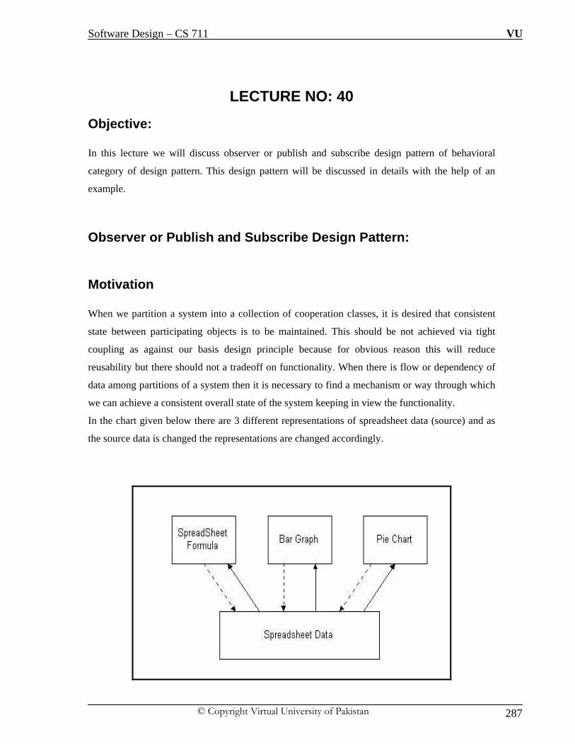
Software Design – CS 711 VU
© Copyright Virtual University of Pakistan 287
LECTURE NO: 40
Objective: In this lecture we will discuss observer or publish and subscribe design pattern of behavioral
category of design pattern. This design pattern will be discussed in details with the help of an
example.
Observer or Publish and Subscribe Design Pattern:
Motivation When we partition a system into a collection of cooperation classes, it is desired that consistent
state between participating objects is to be maintained. This should be not achieved via tight
coupling as against our basis design principle because for obvious reason this will reduce
reusability but there should not a tradeoff on functionality. When there is flow or dependency of
data among partitions of a system then it is necessary to find a mechanism or way through which
we can achieve a consistent overall state of the system keeping in view the functionality.
In the chart given below there are 3 different representations of spreadsheet data (source) and as
the source data is changed the representations are changed accordingly.

Software Design – CS 711 VU
© Copyright Virtual University of Pakistan 288
This diagram reflects the fact that Bar Graph and Pie Chart don’t know about each other so that
anyone can be reused independent of each other, but the interesting thing is that it seems that they
know each other but this idea is very difficult to understand that how it is possible that two
components don’t know about each other. When the data in the spreadsheet (source data) is
changed it is reflected in pie chart and bar graph also immediately. This behavior implies that they
are dependent on data of the spreadsheet and whenever there is a change in spreadsheet pie chart
and bar graph is notified to update the change. There seems to be no reason to believe that the
number of objects representing the data is to be limited may be i-e may be line graph is to be used
in future to represent data.
Observations about the Diagram: If we observe the working of the diagram above we will point out that there exists a consistent
communication model between a set of dependent objects and an object that they are dependent
on. This allows the dependent objects to have their state synchronized with the object that they are
dependent on. The set of dependent objects are referred to as Observers i-e Graphs in our
example. The object on which Observer is dependent is referred to as the subject. i-e Spreadsheet
in our example
Intent of Observer Design Pattern: Define a one-to-many dependency between objects so that when one object changes state, all its
dependents are notified and updated automatically.
Case for Observer Design Pattern An aggregate object such as a list should give you a way to access its elements without exposing
its internal structure. Moreover, you might want to traverse the list in different ways, depending
on what you want to accomplish. But you probably don't want to bloat the List interface with
operations for different traversals, even if you could anticipate the ones you will need. You might
also need to have more than one traversal pending on the same list. The Iterator pattern lets you
do all this. The key idea in this pattern is to take the responsibility for access and traversal out of
the list object and put it into an iterator object. The Iterator class defines an interface for accessing
the list's elements. An iterator object is responsible for keeping track of the current element; that
is, it knows which elements have been traversed already. Observer pattern suggests a publisher-
subscriber model leading to a clear boundary between the set of Observer objects and the Subject
object. A typical observer is an object with interest or dependency in the state of the subject. The

Software Design – CS 711 VU
© Copyright Virtual University of Pakistan 289
subject cannot maintain a static list of such observers as the list of observers for a given subject
could change dynamically. Hence any object with interest in the state of the subject needs to
explicitly register itself as an observer with the subject. Whenever the subject undergoes a change
in its state, it notifies all of its registered observers. Upon receiving notification from the subject,
each of the observers queries the subject to synchronize its state with that of the subject’s.
One-to-Many relationship
There is an explicit relationship between subject and its observer which is reflected from the
scenario which contains a one-to-many relationship between a subject and the set of its
observers. Each of the observer objects has to register itself with the subject to get notified when
there is a change in the subject’s state. We can say that subject will have the registered observers
and it will be easy for the subject to notify the registered observer whenever it undergoes a
change.
Observer Pattern Defined
“This pattern defines a one-to-many relationship between objects so that when there
is change in the state of the one object it should be notified and automatically update
it all dependent”.
Communication Protocol: The subject should provide an interface for registering and unregistering for change notifications.
In the pull model — The subject should provide an interface that enables observers to query the
subject for the required state information to update their state.
In the push model — The subject should send the state information that the observers may be
interested in.

Software Design – CS 711 VU
© Copyright Virtual University of Pakistan 290
Class Diagram of Observer Design Pattern:
Participants in Class Diagram
i. Subject
This class will keeps track of its observers and provides an interface for attaching and detaching
Observer objects
ii. Observer
It defines an interface for update notification
iii. Concrete Subject
As discussed the object being observed will be object of this class, it stores state of interest to
Concrete Observer objects. It responsibility includes sending a notification to its observers when
its state changes
iv. ConcreteObserver
This is object of class who is observing the subject class i-e the observing object. This class stores
state that should stay consistent with the subject's by implementing the Observer update interface
to keep its state consistent with the subject's

Software Design – CS 711 VU
© Copyright Virtual University of Pakistan 291
Consequences:
Support for event broadcasting
Minimal coupling between the Subject and the Observer. Reuse observers without using
subject and vice versa.
Liabilities:
Possible cascading of notifications, Observers are not necessarily aware of each other and
must be careful about triggering updates

Software Design – CS 711 VU
© Copyright Virtual University of Pakistan 292
Observer Design Pattern in Java:
Java provides the Observable/Observer classes as built-in support for the Observer
pattern.
Subject Class The java.util.Observable class is the base Subject class.
i. Any class that wants to be observed extends this class.
ii. Provides methods to add/delete observers
iii. Provides methods to notify all observers
iv. A subclass only needs to ensure that its observers are notified in the appropriately
v. Uses a Vector for storing the observer references
Observer Class:
The java.util.Observer interface is the Observer interface.
i. This interface must be implemented by any observer class.

Software Design – CS 711 VU
© Copyright Virtual University of Pakistan 293
LECTURE NO: 41
Objective: In this lecture we will discuss template method design pattern of behavioral category of design
patterns. This design pattern will be discussed in details with the help of an example.
Template Method Design Pattern or Encapsulating Algorithms: Motivation If we take a look at the dictionary definition of a template we can see that a template is a preset
format, used as a starting point for a particular application so that the format does not have to be
recreated each time it is used. The Template Method pattern can be used in situations when there
is an algorithm, some steps of which could be implemented in multiple different ways. Some
portion of the solution is fixing for all the scenarios and some portion of the solution is specific to
any situation. design patterns in object-oriented applications. The Template Method pattern can
be used in situations when there is an algorithm, some steps of which could be implemented in
multiple different ways. In such scenarios, the Template Method pattern suggests keeping the
outline of the algorithm in a separate method referred to as a template method inside a class,
which may be referred to as a template class, leaving out the specific implementations of the
variant portions (steps that can be implemented in multiple different ways) of the algorithm to
different subclasses of this class. The Template class does not necessarily have to leave the
implementation to subclasses in its entirety. Instead, as part of providing the outline of the
algorithm, the Template class can also provide some amount of implementation that can be
considered as invariant across different implementations. It can even provide default
implementation for the variant parts, if appropriate. Only specific details will be implemented
inside different subclasses. This type of implementation eliminates the need for duplicate code,
which means a minimum amount of code to be written.
Before we jump into the details of “Template method” design pattern, we will briefly discuss
some of the concepts which are required in the discussion.

Software Design – CS 711 VU
© Copyright Virtual University of Pakistan 294
Final Method in Java: In java when we want to restrict the subclass from overriding the super class method, we can
declare that super class method a “Final” method so to keep those methods from overriding
which are making outline of an algorithm.
Hollywood principle: The Hollywood principle prevent us from what we call “Dependency rot” i-e high level
components are dependent on low level components depending on high-level components
depending on sideways components depending on low-level components and so on. When “rot”
sets in it is very difficult to understand how the system is designed for execution.
With Hollywood principle in place, low-level components can be hooked themselves into the
system but high-level components decided when they are needed. We can say that high level
components give “Don’t call us, we will call you” treatment to the low-level components, as
shown in the diagram below that low-level components can participate in computing but low-
level components will never call high level components and on the top of all high-level
component controls when and how to call the low-level components.

Software Design – CS 711 VU
© Copyright Virtual University of Pakistan 295
Hooks or Hot Spots:
The hooks are generally empty methods that are called in superclass (and does nothing because
are empty), but can be implemented in subclasses. Due to this behavior hooks can plug them-
selves into various points in the algorithm if they wish too and beside that subclasses are free to
ignore them. Customization Hooks can be considered a particular case of the template method as
well as a totally different mechanism.

Software Design – CS 711 VU
© Copyright Virtual University of Pakistan 296
Intent of Template Method Design Pattern:
Define the skeleton of an algorithm in an operation, deferring some steps to subclasses.
Template Method lets subclasses redefine certain steps of an algorithm without letting
them to change the algorithm's structure.
Class Diagram:

Software Design – CS 711 VU
© Copyright Virtual University of Pakistan 297
Participating classes
i. Abstract Class
This class defines abstract primitive operations that concrete subclasses define to
implement steps of an algorithm.
ii. Concrete Class:
This class implements the primitive operations to carry out subclass-specific steps of
the algorithm.
When a concrete class is called the template method code will be executed from the base class
while for each method used inside the template method will be called the implementation from
the derived class. The relationship between the Hollywood principle and template method pattern
is somewhat clear because when we are designing with template method we are saying to the
subclasses
“Don’t call us we will call you”

Software Design – CS 711 VU
© Copyright Virtual University of Pakistan 298
Example: Lets' assume we have to develop an application for a travel agency. The travel agency is
managing each trip. All the trips contain common behavior but there are several packages. For
example each trip contains the basic steps:
i. The tourists are transported to the holiday location by plane/train/ships.
ii. Every day they are visiting some place.
iii. They are returning back home.
Our task is to design and implement a system which should simulate the mentioned requirements.
Proposed Class Diagram of Solution

Software Design – CS 711 VU
© Copyright Virtual University of Pakistan 299
Java Code
i. Trip Class
public class Trip {
// This method can’t be overridden by the sub class but we are calling abstract method inside it.
//This will keep intact the outline of the algorithm.
public final void performTrip(){
doComingTransport();
doDayA();
doDayB();
doDayC();
doReturningTransport
}
public abstract void doComingTransport();
public abstract void doDayA();
public abstract void doDayB();
public abstract void doDayC();
public abstract void doReturningTransport();
}
ii. PackageA class
public class PackageA extends Trip
{
public void doComingTransport()
{
System.out.println("The tourists are comming by air ...");
}
public void doDayA() {
System.out.println("The tourists are visiting the garden ...");
}

Software Design – CS 711 VU
© Copyright Virtual University of Pakistan 300
public void doDayB() {
System.out.println("The tourists are going to the museum ...");
}
public void doDayC() {
System.out.println("The tourists are going to mountains ...");
}
public void doReturningTransport() {
System.out.println("The tourists are going home by air ...");
}}
iii. PackageB class
public class PackageB extends Trip {
public void doComingTransport() {
System.out.println("The tourists are comming by train ...");
}
public void doDayA() {
System.out.println("The tourists are visiting the mountain ...");
}
public void doDayB() {
System.out.println("The tourists are going to the olympic stadium ...");
}
public void doDayC() {
System.out.println("The tourists are going to zoo ...");
}
public void doReturningTransport() {
System.out.println("The tourists are going home by train ...");
}
}

Software Design – CS 711 VU
© Copyright Virtual University of Pakistan 301
LECTURE NO: 42
Objective: In this lecture we will discuss memento design pattern of behavioral category of design patterns.
This design pattern will be discussed in details with the help of an example.
Memento or Souvenir Design Pattern: Motivation Consider the case of a calculator object with an undo operation such a calculator could simply
maintain a list of all previous operation that it has performed and thus would be able to restore a
previous calculation it has performed. This would cause the calculator object to become larger,
more complex, and heavyweight, as the calculator object would have to provide additional “undo
functionality” and should maintain a list of all previous operations. The state of an object can
be defined as the values of its properties or attributes at any given point of time. It is sometimes
necessary to capture the internal state of an object at some point and have the ability to restore the
object to that state later in time. The Memento pattern is useful for designing a mechanism to
capture and store the state of an object so that subsequently, when needed, the object can be put
back to this (previous) state. This is more like an “Undo operation” as discussed above. The
Memento pattern can be used to accomplish “Undo Operation” without exposing the object’s
internal structure.
Intent of Memento Design Pattern:
The intent of this pattern is to capture the internal state of an object without violating
encapsulation and thus providing a mean for restoring the object into initial state when
needed.

Software Design – CS 711 VU
© Copyright Virtual University of Pakistan 302
Concepts in Memento:
i. Originator The object whose state needs to be captured is referred to as the originator. When a client wants
to save the state of the originator, it requests the current state from the originator.
ii. Memento Object
The originator stores all those attributes that are required for restoring its state in a separate object
referred to as a Memento and returns it to the client. Thus a Memento can be viewed as an object
that contains the internal state of another object, at a given point of time. A Memento object must
hide the originator variable values from all objects except the originator. In other words, it should
protect its internal state against access by objects other than the originator. Memento should be
designed to provide restricted access to other objects while the originator is allowed to access its
internal state. When the client wants to restore the originator back to its previous state, it simply
passes the memento back to the originator. The originator uses the state information contained in
the memento and puts itself back to the state stored in the Memento object.
Roles in Memento Design Pattern:
i. Originator - the object that knows how to save itself.
ii. Caretaker - the object that knows why and when the Originator needs to save and
restore itself.
iii. Memento - the lock box that is written and read by the Originator, and shepherd by
the Caretaker.

Software Design – CS 711 VU
© Copyright Virtual University of Pakistan 303
Class Diagram
Participating Classes:
i. Memento
This class stores internal state of the Originator object. The state can include any number of state
variables. The Memento must have two interfaces, an interface to the caretaker. This interface
must not allow any operations or any access to internal state stored by the memento and thus
honors encapsulation. The other interface is to the originator and allows the originator to access
any state variables necessary to for the originator to restore previous state.
ii. Originator
It creates a memento object capturing the originators internal state; it then uses the memento
object to restore its previous state.
iii. Caretaker
This class is responsible for keeping the memento. The memento is opaque to the caretaker,
and the caretaker must not operate on it.

Software Design – CS 711 VU
© Copyright Virtual University of Pakistan 304
Processing of the Class
A Caretaker would like to perform an operation on the Originator while having the possibility to
rollback. The caretaker calls the create Memento () method on the originator asking the originator
to pass it a memento object. At this point the originator creates a memento object saving its
internal state and passes the memento to the caretaker. The caretaker maintains the memento
object and performs the operation. In case of the need to undo the operation, the caretaker calls
the set Memento () method on the originator passing the maintained memento object. The
originator would accept the memento, using it to restore its previous state.
Database Transactions and Memento Design Pattern:
Transactions are operations on the database that occur in an atomic, consistent, durable, and
isolated fashion. A transaction can contain multiple operations on the database; each operation
can succeed or fail, however a transaction guarantees that if all operations succeed, the transaction
would commit and would be final. And if any operation fails, then the transaction would fail and
all operations would rollback and leave the database as if nothing has happened. This mechanism
of rolling back uses the memento design pattern.
Consider an object representing a database table, a transaction manager object which is
responsible of performing transactions must perform operations on the table object while having
the ability to undo the operation if it fails, or if any operation on any other table object fails. To be
able to rollback, the transaction manager object would ask the table object for a memento before
performing an operation and thus in case of failure, the memento object would be used to restore
the table to its previous state.
Consequences
Memento protects encapsulation and avoids exposing originator's internal state and
implementation. It also simplifies originator code such that the originator does not need to keep
track of its previous state since this is the responsibility of the Caretaker.

Software Design – CS 711 VU
© Copyright Virtual University of Pakistan 305
Using the memento pattern can be expensive depending on the amount of state information that
has to be stored inside the memento object. In addition the caretaker must contain additional logic
to be able to manage mementos.
Example: Let's use a simple example in Java to illustrate this pattern. As it's a pattern used for undo
frameworks, we'll model a editor. First, the memento needs to be able to save editor contents,
which will just be plain text:
//Memento
public class EditorMemento
{
private final String editorState;
public EditorMemento(String state)
{
editorState = state;
}
public String getSavedState()
{
return editorState;
}}
Now our Originator class, the editor, can use the memento:
//Originator Class
public class Editor
{
//state
public String editorContents;

Software Design – CS 711 VU
© Copyright Virtual University of Pakistan 306
public void setState(String contents)
{
this.editorContents = contents;
}
public EditorMemento save()
{
return new EditorMemento(editorContents);
}
public void restoreToState(EditorMemento memento)
{
editorContents = memento.getSavedState();
}}
Anytime we want to save the state, we call the save() method, and an undo would call the
restoreToState method. Our caretaker can then keep track of all the memento's in a stack for the
undo framework to work.

Software Design – CS 711 VU
© Copyright Virtual University of Pakistan 307
LECTURE NO: 43
Objective: In this lecture we will discuss last pattern of the course and of the behavioral category, command
design pattern. This design pattern will be discussed in details with the help of an example.
Command or Encapsulating Invocation Design Pattern “An object that contains a symbol, name or key that represents a list of commands,
actions or keystrokes”. This is the definition of a macro, one that should be familiar to any
computer user. From this idea the Command design pattern was given birth. The Macro
represents, at some extent, a command that is built from the reunion of a set of other commands,
in a given order.
In general, an object-oriented application consists of a set of interacting objects each offering
limited, focused functionality. In response to user interaction, the application carries out some
kind of processing. For this purpose, the application makes use of the services of different objects
for the processing requirement. In terms of implementation, the application may depend on a
designated object that invokes methods on these objects by passing the required data as
arguments.
Concepts in Command Design Pattern
i. Invoker:
As mention previously, an application is build using the functionality of other objects; in
programming term it means that there should be some object which invokes the methods of other
classes for its own processing. In command design pattern the designated object that invokes
operations on different objects is known as “Invoker” and it is considered as a part of client
application. This is basically a request object which is sending request messages to the classes
where actual implementation lies.
ii. Receiver: The set of objects that actually contain the implementation to offer the services required for the
request processing can be referred to as Receiver objects. In programming sense we can say this

Software Design – CS 711 VU
© Copyright Virtual University of Pakistan 308
response objects because it sends data against a particular request which is send by invoker object
as mention above.
The graphical representation of the working of “Invoker” and “Receiver” is shown below:
In this design, the application that forwards the request and the set of Receiver objects that offer
the services required to process the request are closely tied to each other in that they interact with
each other directly. This could result in a set of conditional if statements in the implementation of
the invoker as shown below:
if (RequestType=TypeA)
{
//do something
}
// Adding a new Type
if (RequestType=TypeB)
{
//do something
}
As we can see above in the code of “Adding a new Type” , we have to open the existing class
add new code in it, we can do it but this is clear violation of “Open/Close Principle” and other
problem is that since invoker is a part of client we are relying on client for successful
implementation of the application by giving him access to the code, in other words we can say
that this design “Tightly Coupled” which is again another violation of design principle.
Suggested Solution: The invoker that issues a request on behalf of the client and the set of service-rendering Receiver
objects can be decoupled. Create an abstraction for the processing to be carried out or the action
to be taken in response to client requests.

Software Design – CS 711 VU
© Copyright Virtual University of Pakistan 309
Intent of Command Design Pattern:
To encapsulate a request in an object.
To allow the parameterization of clients with different requests.
To allow saving the request in a queue.
Promote “invocation of a method on an object” to full object status.
Command Object
The Command pattern suggests creating an abstraction for the processing to be carried out or
the action to be taken in response to client requests. This abstraction can be designed to
declare a common interface to be implemented by different concrete implementers referred to
as Command objects. Each Command object represents a different type of client request and
the corresponding processing as shown below:
A given Command object (Interface class) is responsible for offering the functionality
required to process the request it represents, but it does not contain the actual
implementation of the functionality. It makes use of receiver objects in offering this
functionality.

Software Design – CS 711 VU
© Copyright Virtual University of Pakistan 310
Command Pattern Defined: “It encapsulates a request as an object thereby letting you parameterize other
objects with different requests queue or log request and support undoable
operations”
Class Diagram
The classes participating in the pattern are:
i. Command - declares an interface for executing an operation.
ii. ConcreteCommand - extends the Command interface, implementing the Execute method by
invoking the corresponding operations on Receiver. It defines a link between the Receiver and the
action.
iii. Client - creates a ConcreteCommand object and sets its receiver.
iv. Invoker - asks the command to carry out the request.
v. Receiver - knows how to perform the operations.

Software Design – CS 711 VU
© Copyright Virtual University of Pakistan 311
Flow of Application: Following are the steps in sequence which are performed to execute an application to implement
the command design pattern:
i. Command object encapsulate a request by binding together a set of actions on a specific
receiver by exposing a execute method.
ii. When execute method is called it causes the actions to be invoked on a receiver
iii. From outside no other object know which action will be executed against a receiver
iv. They just know if they will call execute method their request will be served
Advantage and Disadvantages:
Now that we have understood how the pattern works, it's time to take a look at its advantages and
flaws, too.
The intelligence of a command:
There are two extremes that a programmer must avoid when using this pattern:
1. The command is just a link between the receiver and the actions that carry out the request.
2. The command implements everything itself, without sending anything to the receiver.
We must always keep in mind the fact that the receiver is the one who knows how to perform the
operations needed, the purpose of the command being to help the client to delegate its request
quickly and to make sure the command ends up where it should.
Undo and redo actions
As mentioned above, some implementations of the Command design pattern include parts for
supporting undo and redo of actions. In order to do that a mechanism to obtain past states of the

Software Design – CS 711 VU
© Copyright Virtual University of Pakistan 312
Receiver object is needed; in order to achieve this there are two options:
i. Before running each command a snapshot of the receiver state is stored in memory. This
does not require much programming effort but cannot be always applied. For
example doing this in an image processing application would require storing images
in memory after each step, which is practically impossible.
ii. Instead of storing receiver objects states, the set of performed operations are stored in
memory. In this case the command and receiver classes should implement the inverse
algorithms to undo each action. This will require additional programming effort, but
less memory will be required. Sometimes for undo/redo actions the command should
store more information about the state of the receiver objects. A good idea in such
cases is to use the Memento Pattern.
Asynchronous Method Invocation:
Another usage for the command design pattern is to run commands asynchronous in background
of an application. In this case the invoker is running in the main thread and sends the requests to
the receiver which is running in a separate thread. The invoker will keep a queue of commands to
be run and will send them to the receiver while it finishes running them.
Instead of using one thread in which the receiver is running more threads can be created for this.
But for performance issues (thread creation is consuming) the number of threads should be
limited. In this case the invoker will use a pool of receiver threads to run command
asynchronously.
Adding new commands
The command object decouples the object that invokes the action from the object that performs
the action. There are implementations of the pattern in which the invoker instantiates the concrete
command objects. In this case if we need to add a new command type we need to change the
invoker as well. And this would violate the Open Close Principle (OCP). In order to have the
ability to add new commands with minimum of effort we have to make sure that the invoker is
aware only about the abstract command class or interface.
Using composite commands
When adding new commands to the application we can use the composite pattern to group
existing commands in another new command. This way, macros can be created from existing
commands.

Software Design – CS 711 VU
© Copyright Virtual University of Pakistan 313
Hot spot
The main advantage of the command design pattern is that it decouples the object that invokes the
operation from the one that know how to perform it. And this advantage must be kept. There are
implementations of this design pattern in which the invoker is aware of the concrete commands
classes. This is wrong making the implementation more tightly coupled. The invoker should be
aware only about the abstract command class.

Software Design – CS 711 VU
© Copyright Virtual University of Pakistan 314
Example:
In stock exchange, the client creates some orders for buying and selling stocks
(ConcreteCommands). Then the orders are sent to the agent (Invoker).The agent takes the orders
and place them to the StockTrade system (Receiver). The agent keeps an internal queue with the
order to be placed. Let's assume that the StockTrade system is closed each Monday, but the agent
accepts orders, and queue them to be processed later on.
Proposed Class Diagram:

Software Design – CS 711 VU
© Copyright Virtual University of Pakistan 315
Java Code:
i. OrderInterface Class
public interface Order
{
public abstract void execute ( );
}
ii. Reciever Class
class StockTrade {
public void buy() {
System.out.println("You want to buy stocks");
}
public void sell() {
System.out.println("You want to sell stocks ");
}
}
iii. Invoker Class
class Agent {
private m_ordersQueue = new ArrayList();
public Agent() {
}
void placeOrder(Order order) {
ordersQueue.addLast(order);
order.execute(ordersQueue.getFirstAndRemove());
}
}

Software Design – CS 711 VU
© Copyright Virtual University of Pakistan 316
iv. ConcreteCommand Class
v. class BuyStockOrder implements Order {
private StockTrade stock;
public BuyStockOrder ( StockTrade st) {
stock = st;
}
public void execute( ) {
stock . buy( );
}
}
v. ConcreteCommand Class
class SellStockOrder implements Order {
private StockTrade stock;
public SellStockOrder ( StockTrade st) {
stock = st;
}
public void execute( ) {
stock . sell( );
}
}
vi. Client Class
public class Client {
public static void main(String[] args) {
StockTrade stock = new StockTrade();
BuyStockOrder bsc = new BuyStockOrder (stock);
SellStockOrder ssc = new SellStockOrder (stock);
Agent agent = new Agent();
agent.placeOrder(bsc); // Buy Shares
agent.placeOrder(ssc); // Sell Shares
}}
Software Design – CS 711 VU
© Copyright Virtual University of Pakistan 317
LECTURE NO: 44
Objective: In this lecture we will discuss the Architectural Design patterns as a whole and focusing on
“Model View Controller (MVC)” design pattern for discussions in detail.
Overview of Architectural Design Patterns: Architectural patterns express fundamental structural organization schemas for software systems.
They provide a set of predefined subsystems, specify their responsibilities, and include rules and
guidelines for organizing the relationships between them. These patterns represent the
highest-level of patterns in our pattern system. They help you to specify the fundamental structure
of an application. Every development activity that follows is governed by this structure-for
example, the detailed design of subsystems, the communication and collaboration between
different parts of the system, and its later extension.
Each architectural pattern helps you to achieve a specific global system property, such as the
adaptability of the user interface. Patterns that help to support similar properties can be grouped
into following categories.
i. Interactive Systems.
ii. Distributed Systems.
iii. Broker Systems.
The selection of an architectural pattern should be driven by the general properties of the
application at hand. Ask yourself, for example, whether we proposed system is an interactive
system, or one that will exist in many slightly different variants. Pattern selection should be
further influenced by your application's nonfunctional requirements, such as changeability or
reliability.
It is also helpful to explore several alternatives before deciding on a specific architectural pattern.
For example, the Presentation-Abstraction-Control pattern (PAC) and the Model-View-Controller
pattern (MVC) both lend themselves to interactive applications.
Different architectural patterns imply different consequences, even if they address the same or
very similar problems. For example, an MVC architecture is usually more efficient than a PAC

Software Design – CS 711 VU
© Copyright Virtual University of Pakistan 318
architecture. On the other hand, PAC supports multitasking and task-specific user interfaces better
than MVC does.
Most software systems, however, cannot be structured according to a single architectural pattern.
They must support several system requirements that can only be addressed by different
architectural patterns. For example, you may have to design both for flexibility of component
distribution in a heterogeneous computer network and for adaptability of their user interfaces.
You must combine several patterns to structure such systems. However, a particular architectural
pattern, or a combination of several, is not complete software architecture. It remains a
structural framework for a software system that must be further specified and refined. This
includes the task of integrating the application's functionality with the framework, and detailing
its components and relationships, perhaps with help of design patterns and idioms. The selection
of an architectural pattern, or a combination of several, is only the first step when designing the
architecture of a software system.
Note:
In this course we will be discussing “Interactive System” only with discussion on “Model view
Controller (MVC)”.

Software Design – CS 711 VU
© Copyright Virtual University of Pakistan 319
Interactive Systems: Today's systems allow a high degree of user Interaction, mainly achieved with help of graphical
user Interfaces. The objective is to enhance the usability of an application. Usable software
systems provide convenient access to their services, and therefore allow users to learn the
application and produce results quickly.
When specifying the architecture of such systems, the challenge is to keep the functional core
independent of the user interface. The core of Interactive systems is based on the functional
requirements for the system, and usually remains stable. User Interfaces, however, are often
subject to change and adaptation. For example, systems may have to support different user
interface standards, customer-specific 'look and feel' metaphors, or interfaces that must be
adjusted to fit Into a customer's business processes. This requires architectures that support the
adaptation of user Interface parts without causing major effects to application-specific
functionality or the data model underlying the software.
We describe two patterns that provide a fundamental structural organization for interactive
software systems:
i. The Model-View-Controller pattern (MVC) divides an Interactive application into
three components. The model contains the core functionality and data. Views display
information to the user. Controllers handle user input. Views and controllers together
comprise the user interface. A change-propagation mechanism ensures consistency
between the user Interface and the model.
ii. The Presentation-Abstraction-Control pattern (PAC) defines a structure for Interactive
software systems in the form of a hierarchy of cooperating agents. Every agent is
responsible for a specific aspect of the application's functionality and consists of three
components: presentation, abstraction, and control. This subdivision separates the
human-computer Interaction aspects of the agent from its functional core and its
communication with other agents.

Software Design – CS 711 VU
© Copyright Virtual University of Pakistan 320
PAC is not used as widely as MVC, but as an alternative approach for structuring interactive
applications, PAC is especially applicable to systems that consist of several self-reliant
subsystems. PAC also addresses issues that MVC leaves unresolved, such as how to effectively
organize the communication between different parts of the functional core and the user interface.
PAC was first described by Joelle Coutaz. The first application of PAC was in the area of
Artificial Intelligence.

Software Design – CS 711 VU
© Copyright Virtual University of Pakistan 321
Model – View – Controller (MVC): The Model-View-Controller architectural pattern (MVC) divides an interactive application into
three components. The model contains the core functionality and data. Views display information
to the user. Controllers handle user input. Views and controllers together comprise the user
interface. A change-propagation mechanism ensures consistency between the user interface and
the model. Consider a simple information system for political elections with proportional representation.
This offers a spreadsheet for entering data and several kinds of tables and charts for presenting the
current results. Users can interact with the system via a graphical interface. All information
displays must reflect changes to the voting data immediately.
It should be possible to integrate new ways of data presentation such as the assignment of
parliamentary seats to political parties without major impact to the system. The system should
also be portable to platforms with different “look and feel”.

Software Design – CS 711 VU
© Copyright Virtual University of Pakistan 322
Context of the Problem:
We need to have an interactive application with a flexible human-computer interface.
It should be possible to represent one Data with multiple possible representations.
Problem User interfaces are especially prone to change requests. When you extend the functionality of an
application, you must modify menus to access these new functions. A customer may call for a
specific user interface adaptation, or a system may need to be ported to another platform with a
different 'look and feel' standard. Even upgrading to a new release of window system can imply
code changes. The user interface platform of long-lived systems thus represents a moving target.
Different users place conflicting requirements on the user interface. A typist enters information
into forms via the keyboard. A manager wants to use the same system mainly by clicking icons
and buttons. Consequently support for several user interface paradigms should be easily
incorporated. Building a system with the required flexibility is expensive and error prone if the
user interface is tightly interwoven with the functional core. This can result in the need to develop
and maintain several substantially different software systems one for each user interface
implementation. Ensuing changes spread over many modules.
The following forces influence the solution:
i. The same information is presented differently in different windows, for example, in a bar
or pie chart.
ii. The display and behavior of the application must reflect data manipulations immediately.
Changes to the user interface should be easy and even possible at run-time.
iii. Supporting different 'look and feel' standards or porting the user interface should not
affect code in the core of the application.

Software Design – CS 711 VU
© Copyright Virtual University of Pakistan 323
Solution: Basic parts of any application include the following processing steps:
i. Data being manipulated
ii. A user-interface through which this manipulation occurs
iii. The data is logically independent from how it is displayed to the user, display should be
separately designable/evolvable
Model-View-Controller (MVC) was first introduced in the Smalltalk-80 programming
environment [KP88] .MVC divides an interactive application into the three areas: processing,
output, and input.
The model component encapsulates core data and functionality. The model is independent of
specific output representations or input behavior. View components display information to the
user. A view obtains the data from the model. There can be multiple views of the model. Each
view has an associated controller component. Controllers receive input, usually as events that
encode mouse movement, activation of mouse buttons, or keyboard input. Events are translated to
service requests for the model or the view. The user interacts with the system solely through
controllers. The separation of the model from view and controller components allows multiple
views of the same model. If the user changes the model via the controller of one view, all other
views dependent on this data should reflect the changes. The model therefore notifies all views
whenever its data changes. The views in turn retrieve new data from the model and update the
displayed information.
The model component contains the functional core of the application. It encapsulates the
appropriate data, and exports procedures that perform application-specific processing. Controllers
call these procedures on behalf of the user. The model also provides functions to access its data
that are used by view components to acquire the data to be displayed.
The change-propagation mechanism maintains a registry of the dependent components within the
model. All views and also selected controllers register their need to be informed about changes.
Changes to the state of the model trigger the change-propagation mechanism. The change-
propagation mechanism is the only link between the model and the views and controllers.

Software Design – CS 711 VU
© Copyright Virtual University of Pakistan 324
View components present information to the user. Different views present the information of the
model in different ways. Each view defines an update procedure that is activated by the change
propagation mechanism. When the update procedure is called, a view
retrieves the current data values to be displayed from the model and puts them on the screen.
During initialization all views are associated with the model, and register with the change-
propagation mechanism. Each view creates a suitable controller. There is a one-to-one
relationship between views and controllers. Views often offer functionality that allows controllers
to manipulate the display. This Is useful for user-triggered operations that do not affect the model,
such as scrolling. The controller components accept user input as events. How these events are
delivered to a controller depends on the user interface platform. For simplicity let us assume that
each controller Implements an event- handling procedure that Is called for each relevant event.
Events are translated into requests for the model or the associated view. If the behavior of a
controller depends on the state of the model, the controller registers itself with the change-
propagation mechanism and implements an update procedure. For example this is necessary when
a change to the model enables or disables a menu entry.
Graphical Representations of MVC
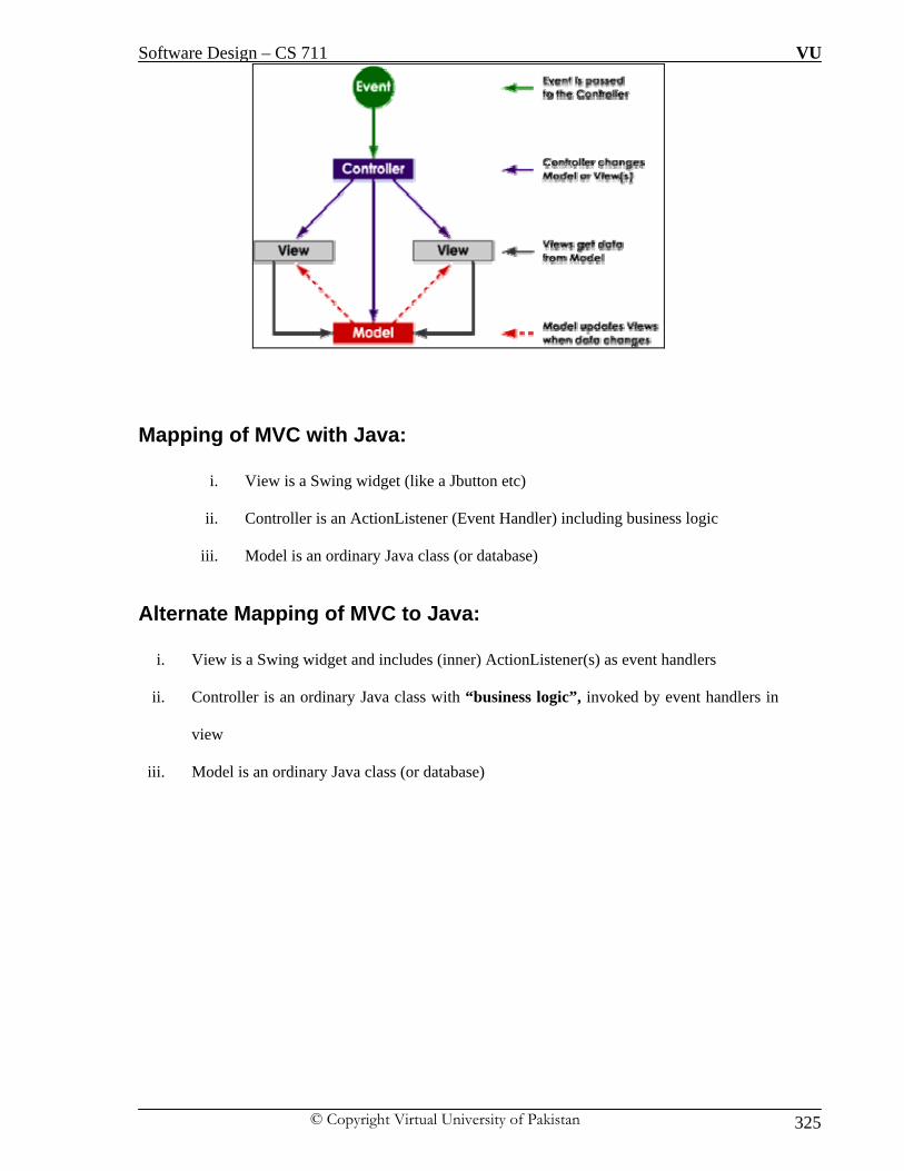
Software Design – CS 711 VU
© Copyright Virtual University of Pakistan 325
Mapping of MVC with Java:
i. View is a Swing widget (like a Jbutton etc)
ii. Controller is an ActionListener (Event Handler) including business logic
iii. Model is an ordinary Java class (or database)
Alternate Mapping of MVC to Java:
i. View is a Swing widget and includes (inner) ActionListener(s) as event handlers
ii. Controller is an ordinary Java class with “business logic”, invoked by event handlers in
view
iii. Model is an ordinary Java class (or database)

Software Design – CS 711 VU
© Copyright Virtual University of Pakistan 326
Example of using MVC: We need to design a program (GUI) based in which we need to multiply a particular value by a
initial value and then each subsequent value should be multiply by the result of the previous
multiplication and this process will continue we close down the application. It should be kept in
mind that initial value is to be replaced with updated multiplied value of the previous calculation
so that it will become initial value for the next calculation.
Step-wise Processing of the Solution

Software Design – CS 711 VU
© Copyright Virtual University of Pakistan 327
Java Code:
i. View Class:
This View doesn't know about the Controller, except that it provides methods for registering a
Controller's listeners. Other organizations are possible (e. g, the Controller's listeners are non-
private variables that can be referenced by the View, the View calls the Controller to get
listeners, the View calls methods in the Controller to process actions)
import java.awt.*;
import javax.swing.*;
import java.awt.event.*;
class CalcView extends JFrame {
//... Constants
private static final String INITIAL_VALUE = "1";
//... Components
private JTextField m_userInputTf = new JTextField(5);
private JTextField m_totalTf = new JTextField(20);
private JButton m_multiplyBtn = new JButton("Multiply");
private JButton m_clearBtn = new JButton("Clear");
private CalcModel m_model;
CalcView(CalcModel model) {
//... Set up the logic
m_model = model;
m_model.setValue(INITIAL_VALUE);
//... Initialize components
m_totalTf.setText(m_model.getValue());
m_totalTf.setEditable(false);
//... Layout the components.

Software Design – CS 711 VU
© Copyright Virtual University of Pakistan 328
JPanel content = new JPanel();
content.setLayout(new FlowLayout());
content.add(new JLabel("Input"));
content.add(m_userInputTf);
content.add(m_multiplyBtn);
content.add(new JLabel("Total"));
content.add(m_totalTf);
content.add(m_clearBtn);
//... finalize layout
this.setContentPane(content);
this.pack();
this.setTitle("Simple Calc - MVC");
// The window closing event should probably be passed to the
// Controller in a real program, but this is a short example.
this.setDefaultCloseOperation(JFrame.EXIT_ON_CLOSE);
}
void reset() {
m_totalTf.setText(INITIAL_VALUE);
}
String getUserInput() {
return m_userInputTf.getText();
}
void setTotal(String newTotal) {
m_totalTf.setText(newTotal);
}
void showError(String errMessage) {
JOptionPane.showMessageDialog(this, errMessage);
}
void addMultiplyListener(ActionListener mal) {
m_multiplyBtn.addActionListener(mal);

Software Design – CS 711 VU
© Copyright Virtual University of Pakistan 329
}
void addClearListener(ActionListener cal) {
m_clearBtn.addActionListener(cal);
}
}
ii. Controller Class The controller processes the user requests. It is implemented here as an Observer pattern --
the Controller registers listeners that are called when the View detects a user interaction.
Based on the user request, the Controller calls methods in the View and Model to accomplish
the requested action.
import java.awt.event.*;
public class CalcController {
//... The Controller needs to interact with both the Model and View.
private CalcModel m_model;
private CalcView m_view;
/** Constructor */
CalcController(CalcModel model, CalcView view) {
m_model = model;
m_view = view;
//... Add listeners to the view.
view.addMultiplyListener(new MultiplyListener());
view.addClearListener(new ClearListener());
}
// inner class MultiplyListener
/** When a multiplication is requested.
* 1. Get the user input number from the View.
* 2. Call the model to multiply by this number.
* 3. Get the result from the Model.
* 4. Tell the View to display the result.

Software Design – CS 711 VU
© Copyright Virtual University of Pakistan 330
* If there was an error, tell the View to display it.
*/
class MultiplyListener implements ActionListener {
public void actionPerformed(ActionEvent e) {
String userInput = "";
try {
userInput = m_view.getUserInput();
m_model.multiplyBy(userInput);
m_view.setTotal(m_model.getValue());
} catch (NumberFormatException nfex) {
m_view.showError("Bad input: '" + userInput + "'");
}
}
}//end inner class MultiplyListener
// inner class ClearListener
/** 1. Reset model.
* 2. Reset View.
*/
class ClearListener implements ActionListener {
public void actionPerformed(ActionEvent e) {
m_model.reset();
m_view.reset();
}
}// end inner class ClearListener
}

Software Design – CS 711 VU
© Copyright Virtual University of Pakistan 331
iii. Model Class
The model is independent of the user interface. It doesn't know if it's being used from a text-
based, graphical, or web interface. This is the same model used in the presentation example.
import java.math.BigInteger;
public class CalcModel {
//... Constants
private static final String INITIAL_VALUE = "0";
//... Member variable defining state of calculator.
private BigInteger m_total; // The total current value state.
/** Constructor */
CalcModel() {
reset();
}
/** Reset to initial value. */
public void reset() {
m_total = new BigInteger(INITIAL_VALUE);
}
/** Multiply current total by a number.
*@param operand Number (as string) to multiply total by.
*/
public void multiplyBy(String operand) {
m_total = m_total.multiply(new BigInteger(operand));
}
/** Set the total value.
*@param value New value that should be used for the calculator total.
*/
public void setValue(String value) {
m_total = new BigInteger(value);
}
/** Return current calculator total. */
public String getValue() {

Software Design – CS 711 VU
© Copyright Virtual University of Pakistan 332
return m_total.toString(); }}
iv. Main Class
import javax.swing.*;
public class CalcMVC {
//... Create model, view, and controller. They are
// created once here and passed to the parts that
// need them so there is only one copy of each.
public static void main(String[] args)
{
CalcModel model = new CalcModel();
CalcView view = new CalcView(model);
CalcController controller = new CalcController(model, view);
view.setVisible(true);
} }

Software Design – CS 711 VU
© Copyright Virtual University of Pakistan 333
LECTURE NO: 45
Objective: In the last lecture we will have a discussion on refactoring followed by discussion on “Anti-
Patterns”.”Anti-Patterns” will be discussed along with its categories.
What is Refactoring: Refactoring is a disciplined technique for restructuring an existing body of code, altering its
internal structure without changing its external behavior. Its heart is a series of small behavior
preserving transformations. Each transformation (called a 'refactoring') does little, but a sequence
of transformations can produce a significant restructuring. I don’t want to proclaim refactoring as
the cure for all software ills. It is no “silver bullet.” Yet it is a valuable tool, a pair of silver pliers
that helps you keep a good grip on your code. Refactoring is a tool that can, and should, be used
for several purposes. Without refactoring, the design of the program will decay. As people change
code—changes to realize short-term goals or changes made without a full comprehension of the
design of the code—the code loses its structure. It becomes harder to see the design by reading
the code. Refactoring is rather like tidying up the code. Work is done to remove bits that aren’t
really in the right place. Loss of the structure of code has a cumulative effect. The harder it is to
see the design in the code, the harder it is to preserve it, and the more rapidly it decays. Regular
refactoring helps code retain its shape. Poorly designed code usually takes more code to do the
same things, often because the code quite literally does the same thing in several places. Thus an
important aspect of improving design is to eliminate duplicate code. The importance of this lies in
future modifications to the code. Reducing the amount of code won’t make the system run any
faster, because the effect on the footprint of the programs rarely is significant. Reducing the
amount of code does, however, make a big difference in modification of the code. The more code
there is, the harder it is to modify correctly. There’s more code to understand. You change this bit
of code here, but the system doesn’t do what you expect because you didn’t change that bit over
there that does much the same thing in a slightly different context. By eliminating the duplicates,
you ensure that the code says everything once and only once, which is the essence of good design.
Programming is in many ways a conversation with a computer. You write code that tells the
computer what to do, and it responds by doing exactly what you tell it. In time you close the gap
between what you want it to do and what you tell it to do. Programming in this mode is all about

Software Design – CS 711 VU
© Copyright Virtual University of Pakistan 334
saying exactly what you want. But there is another user of your source code. Someone will try to
read your code in a few months’ time to make some changes. We easily forget that extra user of
the code, yet that user is actually the most important. Who cares if the computer takes a few more
cycles to compile something? It does matter if it takes a programmer a week to make a change
that would have taken only an hour if she had understood your code. The trouble is that when you
are trying to get the program to work, you are not thinking about that future developer. It takes a
change of rhythm to make changes that make the code easier to understand. Refactoring helps you
to make your code more readable. When refactoring you have code that works but is not ideally
structured. A little time spent refactoring can make the code better communicate its purpose.
Programming in this mode is all about saying exactly what you mean. Often this future developer
is me. Here refactoring is particularly important. I’m a very lazy programmer. One of my forms of
laziness is that I never remember things about the code I write. Indeed, I deliberately try not
remember anything I can look up, because I’m afraid my brain will get full. I make a point of
trying to put everything I should remember into the code so I don’t have to remember it. This
understandability works another way, too. I use refactoring to help me understand unfamiliar
code. When I look at unfamiliar code, I have to try to understand what it does. I look at a couple
of lines and say to myself, oh yes, that’s what this bit of code is doing. With refactoring I don’t
stop at the mental note. I actually change the code to better reflect my understanding, and then I
test that understanding by rerunning the code to see if it still works. Early on I do refactoring like
this on little details. As the code gets clearer, I find I can see things about the design that I could
not see before. Had I not changed the code, I probably never would have seen these things,
because I’m just not clever enough to visualize all this in my head. Ralph Johnson describes these
early refactoring as wiping the dirt off a window so you can see beyond. When I’m studying code
I find refactoring leads me to higher levels of understanding that otherwise I would miss. Smells
(especially code smells) are warning signs about potential problems in code. Not all smells
indicate a problem, but most are worthy of a look and a decision. Smells usually describe
localized problems. It would be nice if people could find problems easily across a whole system.
But humans aren't so good at that job; local smells work with our tendency to consider only the
part we're looking at right now.

Software Design – CS 711 VU
© Copyright Virtual University of Pakistan 335
Measured Smells
i. They're dead easy to detect.
ii. They're objective (once you decide on a way to count and a maximum acceptable score).
They're horrible. And, they're common.
iii. We can think of these smells as being caught by software metric. Each metric tends to
catch different aspects of why code isn't as good as it could be.
Applying Refactoring:
We try to select refactoring that improves the code in each trip through the cycle. Because none of
the steps change the program's observable behavior, the program remains in a working state.
Thus, the cycle improves code but retains behavior. The trickiest part of the whole process is
identifying the smell, here it would be worth mentioning that it may happen that multiple cycles
yields no optimization in the existing code because it is not a rule that applying certain process
will improve the code but it good practice to look for improvement.

Software Design – CS 711 VU
© Copyright Virtual University of Pakistan 336
What are Anti-Patterns: Software systems are becoming increasingly more complex, which makes it hard to properly
design and implement them. A study has shown that on average five out of six software projects
fail. They suffer from either cost overruns, time overruns or are cancelled altogether. The reasons
for such failures are manifold, but one can observe that the same mistakes are repeated again and
again. This is even the case in situations where proven and working solutions exist. Design
Patterns, solutions to recurring problems, explain ”best practices” in software development. They
provide knowledge that can easily be reused in different types of software; however, even Design
Patterns – used in the wrong context or applied inappropriately – can have negative consequences. Jim Coplien: “Something that looks like a good idea, but which backfires badly when
applied”
The term was coined in 1995 by Andrew Koenig, inspired by Gang of Four's book Design
Patterns, which developed the concept of design patterns in the software field. The term was
widely popularized three years later by the book AntiPatterns, which extended the use of the term
beyond the field of software design and into general social interaction.
These are the application of such a pattern that may be commonly used but is ineffective and/or
counterproductive in practice for that particular scenario. The AntiPattern may be the result of a
manager or developer not knowing any better, not having sufficient knowledge or experience in
solving a particular type of problem, or having applied a perfectly good pattern in the
wrong context.
AntiPatterns are useful in several ways:
i. They provide a common vocabulary for known dysfunctional software
designs and solutions, as every AntiPattern has a short and descriptive
name like Gold Class etc.
ii. They help detecting problems in the code, the architecture and the
management of software projects.
iii. They describe both, preventive measures as well as refactored solutions,
which can save software projects in trouble.

Software Design – CS 711 VU
© Copyright Virtual University of Pakistan 337
Famous Anti-Patterns: Some of the commonly known anti-patterns are as below, however it should be noted that there
exists many anti-pattern and it is possible that you may never face any anti-pattern in your
lifetime.
i. Patterns Fetish or Pattern Craze
ii. The Swiss-Army Knife
iii. The Crystal Ball
iv. The God Class
v. Abstraction inversion
i. Patterns Fetish or Pattern Craze This pattern truly depicts that fact that everything one knows is not always true for application;
this anti-pattern refers to Unreasonable and excessive use of design patterns. Software Designer
looks for places to use patterns because of the knowledge of the design pattern it is forced to get
applied irrespective of the fact it is needed or not i-e “Right thing wrong place”.
Suppose we want to print hello world it might happen that we can apply Abstract Factory
pattern for this simple task as shown below:

Software Design – CS 711 VU
© Copyright Virtual University of Pakistan 338
Instead of this heavy weight code to perform the simple task we can write very simple and less
code as shown below:

Software Design – CS 711 VU
© Copyright Virtual University of Pakistan 339
ii. Swiss Army Knife
This is the scenario where for using applying polymorphism, we have more interfaces
than classes. The number of interfaces on a class produces a severe case of instability. A
Basic Litmus-Test for the Swiss Army Knife anti-pattern is by asking this simple
question:
Do your classes implement more than 3 interfaces?
If yes than it is going to be an issue in term of software maintenance.
Look at the code below in the box:
The syntax is ok but semantically we have written a code which will be nightmare for us because
intentionally or un-intentionally we have written a class which is implementing obviously many
more than 3 interfaces which pass our litmus test for “Swiss Army Knife”. What need to
understand is:
i. More != Better
ii. Too many interfaces creates confusion
iii. Maintenance problems
iv. Each interface requires implementation of items on that interface
v. Do your classes actually need to share an interface?
Solutions: It might happen that our class needs to USE another class Aggregation, Composition or
“Façade” design pattern because it selects inner objects to do the work rather than interfaces.

Software Design – CS 711 VU
© Copyright Virtual University of Pakistan 340
iii. The Crystal Ball
This scenario reflect non-availability of future requirements or we are designing for the
unknown or future potentials where there is little to no justification. It is true that we do
assumptions while we are designing but there are no un-scoped assumptions or we can say
that there are no assumptions about the assumptions because it we assume too much than
design reaches out too far and assumes too much. The Base classes are overly generic for the
problem domain and they implement methods/attributes that add little value sub-classes have
little in common with their Siblings and we adding new subclasses because we have no
justification for them i-e we think that we are doing inheritance but in-fact we are not doing
inheritance.
Sesame Street Rule:
“One of these things is not like the other”
Example:

Software Design – CS 711 VU
© Copyright Virtual University of Pakistan 341
iv. The God Class
This is a scenario where are trying to write all the possibilities of the problem in one class and
in search for simplicity we indirectly invite complexity. The logo of this anti-pattern is:
One “Do It All” class
This logo implicitly mean that we ignore design rules for optimization i-e inheritance,
polymorphism, abstract classes and others because we are trying to write a class which will
solve our all the problem.
Symptoms
i. Major tip-off = an excessive number of methods
ii. Lack of specialization, low cohesion
iii. One class manages all behaviors for what probably should be “logical subtypes”
The code below in the box show that for every type of customer we are writing some code
without taking into consideration their commonalities so that we can have a further optimized
version of our code.

Software Design – CS 711 VU
© Copyright Virtual University of Pakistan 342
A better version of the same code is as below:
public abstract class customer
{
Public abstract void dosomething();
}
public class customerGold extends customer
{
public dosomething()
{
//provide Gold customer specific implementation.
}}

Software Design – CS 711 VU
© Copyright Virtual University of Pakistan 343
v. Abstraction Inversion This anti-pattern comes up with a design when users of a construct need functions implemented
within it but not exposed by its interface. The result is that the users re-implement the required
functions in terms of the interface, which in its turn uses the internal implementation of the same
functions. This means that essential methods are missing which are required by the user, this
scenario we called “Missing requirement” problem. The user of such a re-implemented function
may seriously underestimate its running-costs. The user of the construct is forced to doubt his
implementation with complex mechanical details. Many users attempt to solve the same problem,
increasing the risk of error and give rise to non-standard version of the method i-e each user will
have its own implementation which will ultimately generate inconsistent design component.