lecture 9: internet
TRANSCRIPT

Lecture 9: Internet
CS/ECE 438: Communication Networks
Prof. Matthew Caesar
March 10, 2010

The Big Picture
you are here
000100011100100100011101

Topics
• Overview of the Internet
– Message formats, topology, history, interconnection
• Internet Routing
– Delivery models: Unicast, Multicast, Anycast
– Forwarding (MTU, tunneling/VPNs), ICMP
– Network management (TE)
• Internet Addressing/Naming
– DNS, NAT; ARP, DHCP; Mobility

Overview of the Internet

What is the Internet?
• 30,925 ISPs, 2,600,000 routers, 289,989 subnets, 625,226,456 hosts
• Rich array of systems and protocols• ISPs compete for business, hide private information, end-hosts misbehave, complex failure modes, cross-dependencies and oscillations
• Yet everyone must cooperate to ensure reachability– Relies on complex interactions across multiple systems and protocols

Internetworking
• You currently understand– How to build a network on one physical medium– How to connect networks (except routing)
• You have experimented with– Construct a reliable byte stream– Deal with
• Finite frame length• Corrupt frames• Frame loss
• Now: Internetworking– Address heterogeneity of networks– Address rapid growth of Internet (scalability issues)

Internetworking
• Dealing with simple heterogeneity issues– Defining a service model
– Defining a global namespace
– Structuring the namespace to simplify forwarding
– Building forwarding information (routing)
– Translating between global and local (physical) names
– Hiding variations in frame size limits
• Dealing with global scale
• Moving forward with IP
Internetworks
reading: Peterson and Davie, Ch. 4 + Sect. 9.1
• Basics of internetworking (heterogeneity)– The IP protocol, address resolution, and control messages
• Routing
• Global internets (scale)– Address assignment and translation
– Hierarchical routing
– Name translation and lookup
– Multicast traffic
• Future internetworking: IPv6
Basics of Internetworking
• What is an internetwork– Illusion of a single (direct link) network
– Built on a set of distributed heterogeneous networks
– Abstraction typically supported by software
• Properties– Supports heterogeneity
• Hardware, OS, network type, and topology independent
– Scales to global connectivity
• The Internet is the specific global internetwork that grew out of ARPANET

Internetworking
ATMATM
EthernetEthernet
FDDIFDDI

Internet Protocol (IP)
• Network-level protocol for the Internet
• Operates on all hosts and routers
– Routers are nodes connecting distinct networks to the Internet
ModemATMFDDIEthernet
FTP TFTPNVHTTP
TCP UDP
IP
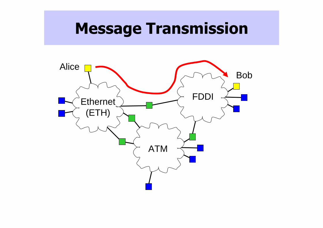
Message Transmission
Ethernet(ETH)
FDDI
ATM
AliceBob
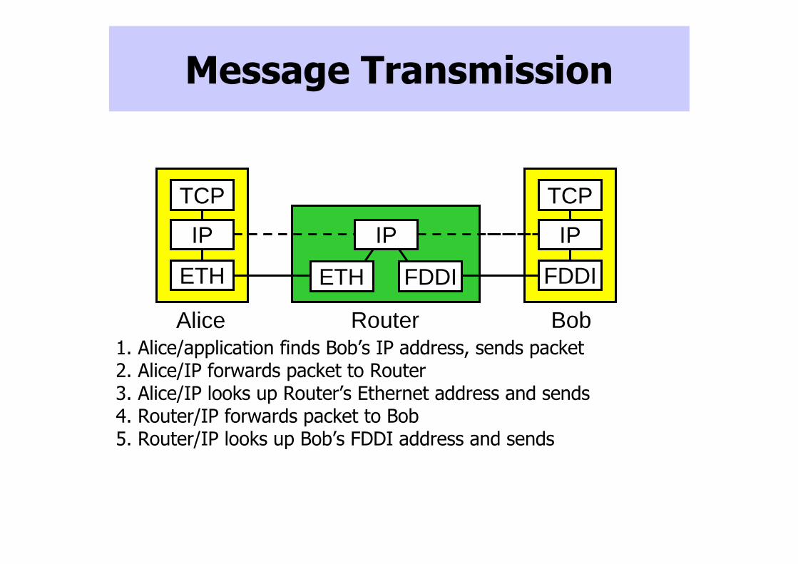
Message Transmission
1. Alice/application finds Bob’s IP address, sends packet2. Alice/IP forwards packet to Router3. Alice/IP looks up Router’s Ethernet address and sends4. Router/IP forwards packet to Bob5. Router/IP looks up Bob’s FDDI address and sends
TCP
IP
Alice
IP
TCP
BobRouter
IP
FDDI FDDIETHETH

Internet Protocol Service Model
• Service provided to transport layer (TCP, UDP)– Global name space
– Host-to-host connectivity (connectionless)
– Best-effort packet delivery
• Not in IP service model– Delivery guarantees on bandwidth, delay or loss
• Delivery failure modes– Packet delayed for a very long time
– Packet loss
– Packet delivered more than once
– Packets delivered out of order

Simple Internetworking with IPv4
• Host addressing
• Forwarding
• Fragmentation and reassembly
• Error reporting/control messages

Overview of packet forwarding
• Hosts assigned topology-dependent addresses
• Routers advertise address blocks (“prefixes”)
• Routers compute “shortest” paths to prefixes
• Map IP addresses to names with DNS
• More on “Routing” and “Naming” later
Robert
twitter.com
23.2.0.0/24
81.2.0.0/24
11.1.0.0/16
4.0.0.0/8Prefix HopsIF
Routing Table at B
D 1
4.0.0.0/8Prefix HopsIF
Routing Table at C
D 1
4.0.0.0/8Prefix HopsIF
Routing Table at A
B 2
AB
C D11.1.0.1
11.1.8.7
23.2.0.1
81.2.0.1 4.5.16.2
4.18.5.1
4.9.0.1
IP address
4.0.0.0/8
Prefix
Robert’s local DNS server
Twitter’s authoritativeDNS server
.com authoritativeDNS sever

Routing and Forwarding

Roadmap
• IP Forwarding
– Fragmentation and reassembly, ICMP, VPNs
– Delivery models
• IP Routing
– Routing across ISPs
– How inter- and intra-domain routing work together
– How Ethernet and intra-domain routing work together

Datagram Forwarding with IP
• Hosts and routers maintain forwarding tables– List of <prefix, next hop> pairs– Often contains a default route
• Pass unknown destination to provider ISP
– Simple and static on hosts, edge routers• Complex and dynamic on core routers
• Packet forwarding– Compare network portion of address with <network/host,
next hop> pairs in table• Send directly to host on same network• Send to indirectly (via router on same network) to host on different network
– Use ARP to get hardware address of host/router

IP Packet Size
• Problem
– Different physical layers provide different limits on frame length
• Maximum transmission unit (MTU)
– Source host does not know minimum value
• Especially along dynamic routes

IP Fragmentation and Reassembly
• Solution– When necessary, split IP packet into acceptably sized packets
prior to sending over physical link
• Questions– Where should reassembly occur?– What happens when a fragment is damaged/lost?
Size=1300
H1 R1 R2 H2
MTU=1500 MTU=450
Size=450, offset=0
Size=450, offset=450
Size=400, offset=900
MTU=600

IP Fragmentation and Reassembly
• Fragments: self-contained IP datagrams• Reassemble at destination
– Minimizes refragmentation
• If one or more fragments are lost – Drop all fragments in packet
• Avoid fragmentation at source host– Transport layer should send packets small enough to fit into one MTU of local physical network
– Must consider IP header

FlagsVersion HLen TOS Length
Ident OffsetTTL Protocol Checksum
SourceAddrDestinationAddr
Options (variable) Pad(variable)
Data4-bit version
IPv4 = 4, IPv6 = 64-bit IP header length
Counted in 32-bit words, minimum value is 5
8-bit type of service field (TOS)Specifies priorities: priority level, minimize delay, maximize throughput, maximize reliability, minimize monetary cost, etcMostly unused
Total Length of datagram, including header and data
Counted in bytesMaximum size is 65536 bytes
16-bit packet ID (Fragmentation support)All fragments from the same packet have the same IDSender must make sure ID is unique for that (src,dest) pair, for the time the datagram will be active in the Internet
3-bit flags R = Reserved (unused)DF = Don’t fragment (if set, router returns
ICMP if MTU too small)MF = More fragments (1 indicates datagram has additional fragments on the way, 0 indicates this is the last fragment)
13-bit fragment offset into packet (Fragmentation)Indicates where in packet this fragment belongs (first fragment has offset zero, fragment starting at byte X has offset of X/8)Counted in 8-byte words
IP Packet Format
0 4 8 16 19 31
8-bit time-to-live field (TTL)Initial value: 128 (Windows), 64 (Linux)Hop count decremented at each routerPacket is discarded if TTL = 0
8-bit protocol field (specifies encapsulated protocol)TCP = 6, UDP = 17
16-bit IP checksum on headerSince some header fields change at each router, this is recomputed at each router
32-bit source IP address32-bit destination IP address

Path MTU discovery
• Set “don’t fragment” bit in IP header, size is MTU of first hop
• Interface with too-small MTU responds back with “ICMP” message– Unfortunately, many networks drop ICMP traffic
• Reduce packet size, repeat until discover smallest MTU on path
• Binary search– Better yet: note there are small number of MTUsin the Internet

IP Fragmentation and Reassembly
ETH IP (1480)
FDDI IP (1480)
PPP IP (456)
PPP IP (512)
PPP IP (512)
ETH IP (456)
ETH IP (512)
ETH IP (512)
Start of headerIdent = x 0 Offset 0
Rest of header1400 data bytes
Start of headerIdent = x 1 Offset 0
Rest of header512 data bytes
Start of headerIdent = x 1 Offset 512
Rest of header512 data bytes
Start of headerIdent = x 0 Offset 1024
Rest of header456 data bytes
H1 R1 R2 R3 H2
ETH (MTU=1500)
FDDI (MTU=4500)
PPP (MTU=535)
ETH (MTU=1500)

Internet Control Message Protocol (ICMP)
• IP companion protocol
– Handles error and control messages
– Used for troubleshooting and measurement
ModemATMFDDIEthernet
FTP TFTPNVHTTP
TCP UDP
IP ICMP

ICMP
• Used for pings (probing remote hosts), traceroutes (learning set of routers along a path), etc.
• Error Messages– Host unreachable, fragmentation failed, TTL exceeded, invalid header
• Control Messages– Echo/ping request and reply, timestamps, route redirect

Virtual Private Networks
• Goals
– Controlled connectivity
• Restrict forwarding to authorized hosts
– Controlled capacity
• Change router drop and priority policies
• provide guarantees on bandwidth, delay, etc.
• Virtual Private Network
– A group of connected subnets
– Connections may be over shared network
– Similar to VLANs, but over IP allowing the use of heterogeneous networks

Virtual Private Networks
C
A B
M
K L
C
A BM
K L

Tunneling
• IP Tunnel
– Virtual point-to-point link between an arbitrarily connected pair of nodes
Network 1
Network 1
Network 2
Network 2InternetworkInternetwork
R1 R2
IP Tunnel
IP Dest = 2.xIP Payload
IP Dest = 10.0.0.1
10.0.0.1
IP Dest = 2.xIP Payload
IP Dest = 2.xIP Payload

Tunneling
• Advantages
– Transparent transmission of packets over a heterogeneous network
– Only need to change relevant routers
• Disadvantages
– Increases packet size
– Processing time needed to encapsulate and unencapsulate packets
– Management at tunnel-aware routers

Delivery models
• Unicast– One source, one destination
– Widely used (web, p2p, streaming, many other protocols)
• Broadcast• Multicast• Anycast
A
B C
D
G
E
JH
F
I

Delivery models
• Unicast• Broadcast
– One source, all destinations
– Used to disseminate control information, perform service discovery
• Multicast• Anycast
A
B C
D
G
E
JH
F
I

Delivery models
• Unicast• Broadcast• Multicast
– One source, several (prespecified) destinations
– Used within some ISP infrastructures for content delivery, overlay networks
• Anycast
A
B C
D
G
E
JH
F
I

Delivery models
• Unicast• Broadcast• Multicast• Anycast
– One source, route to “best”destination
– Used in DNS, content distribution
A
B C
D
G
E
JH
F
I

Robin Kravets and Matt Caesar, UIUC - Spring 2009
36
Internet Multicast
• Motivation and challenges
• Support strategy
• IP multicast service model
• Multicast in the Internet
• Multicast routing protocols
• Limitations

Robin Kravets and Matt Caesar, UIUC - Spring 2009
37
Multicast: motivating example
• Example: Live 8 concert
– Send ~300 Kbps video streams
– Peak usage > 100,000 simultaneous users
– Consumes > 30 Gbps
• If 1000 people in UIUC, and if the concert is broadcast from a single location, then 1000 unicast streams are sent from that location to UIUC

Problem: this approach does not scale

Alternative: build trees
Copy data at routers, at most one copy of a data packet per link
“Group members” kept track of by routers in real time, tree updated to reflect membership changes
LANs locally link-layer multicast by broadcasting

Multicast routing approaches
• Kinds of trees– Source-specific trees vs. Shared tree
• Layer– Data-link, network, application
• Tree computation methods– Link state vs. Distance vector

Robin Kravets and Matt Caesar, UIUC - Spring 2009
Source-specific trees
• Each source is the root of its own tree
• One tree per source
• Tree consists of shortest paths to each receiver
A
B C
D
G
E
JH
F
I
FMember of multicast group
Sender to multicast group

Robin Kravets and Matt Caesar, UIUC - Spring 2009
Source-specific trees
• Each source is the root of its own tree
• One tree per source
• Tree consists of shortest paths to each receiver
A
B C
D
G
E
JH
F
I
FMember of multicast group
Sender to multicast group
J

Robin Kravets and Matt Caesar, UIUC - Spring 2009
43
Shared Tree
• One tree used by all members of a group
• Rooted at “rendezvous point”(RP)
• Less state to maintain, but hard to pick a tree that’s “good” for everybody!
A
B C
D
G
E
JH
F
I
J
RP

Robin Kravets and Matt Caesar, UIUC - Spring 2009
44
Shared Tree
• Ideally, find a “Steiner tree”minimum-weighted tree connecting only the multicast members
– Unfortunately, this is NP-hard
• Instead, use heuristics
– E.g., find a minimum spanning tree (much easier)
A
B C
D
G
E
JH
F
I
J
RP

Multicast service model
• Unicast: packets are delivered to one host
• Broadcast: packets are delivered to all hosts
• Multicast: packets are delivered to all hosts that have joined the multicast group
– Multicast group identified by a multicast address
NETWORKSender
Receiver0
Receiver1
Receiver2
[G,data]
[join,0]
[join,1]
[join,2]
[G,data]
[G,data]
[G,data]

Concepts
• Reverse-path forwarding– Regular routing protocols compute shortest path tree, so
forward multicast packets along “reverse” of this tree
• Truncated reverse-path forwarding– Routers inform upstreams whether the upstream is on the
router’s shortest path, to eliminate unnecessary broadcasting
• Flood-and-prune– Hosts must explicitly ask to not be part of multicast tree
– Alternative: host explicitly sends “join” request to add self to tree

Reverse-path forwarding
• Extension to DV routing• Packet forwarding
– If incoming link is shortest path to source
– Send on all links except incoming
– Packets always take shortest path• Assuming delay is symmetric
• Issues– Routers/LANs may
receive multiple copies

Truncated reverse-path forwarding
• Eliminate unnecessary forwarding– Routers inform upstreams if used on shortest path
– Explicit group joining per-LAN
• Packet forwarding– If not a leaf router, or have members
– Then send out all links except incoming
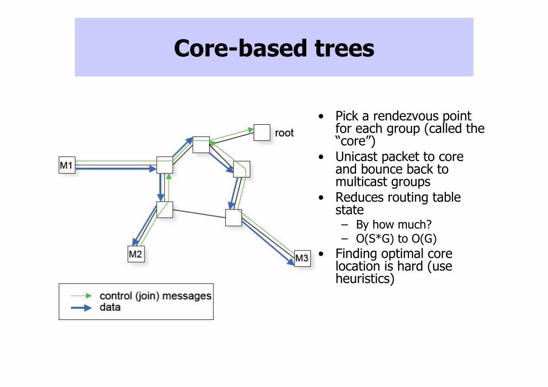
Core-based trees
• Pick a rendezvous point for each group (called the “core”)
• Unicast packet to core and bounce back to multicast groups
• Reduces routing table state – By how much?– O(S*G) to O(G)
• Finding optimal core location is hard (use heuristics)

Robin Kravets and Matt Caesar, UIUC - Spring 2009
50
Other IP Multicast protocols
• Three ways for senders and receivers to “meet”:– Broadcast membership advertisement from each receiver
to entire network • example: MOSPF
– Broadcast initial packets from each source to entire network; non-members prune • examples: DVMRP, PIM-DM
– Specify “meeting place” to which sources send initial packets, and receivers join; requires mapping between multicast group address and “meeting place”• examples: PIM-SM
• What are some problems with IP-layer Multicast?

Problems with Network Layer Multicast
• Scales poorly with number of groups
– Routers must maintain state for every group
– Many groups traverse core routers
• Higher-layer functionality is difficult
– NLM: best-effort delivery
– Reliability, congestion control, transcoding for NLM complicated
• Deployment is difficult and slow
– ISPs reluctant to turn on NLM

Problems with Network Layer Multicast
• Inconsistent with ISP charging model
– Charging today is based on send rate of customer
– But one multicast packet at ingress may cause millions to be sent on egress
• Troublesome security model
– Anyone can send to group
– Denial of service attacks on groups

Alternative: Application-layer Multicast
• Let hosts do all packet copying, tree construction– Only require unicast from network
– Hosts construct unicast channels between themselves to form tree
• Benefits– No need to change IP, or for ISP cooperation
– End hosts can prevent untrusted hosts from sending
– Easy to implement reliability (per-hop retransmissions)
• Downsides– Stretch penalty (latency), Stress penalty (multiple
retransmissions over same physical link

Example of Application-level Multicast

IPv6: proposed next generation of IP
• Problems with IPv4– Running out of address space
• Projected depletion 2015-2032
– Forwarding complicated by fragmentation, checksum computation, many unused fields
• IPv6 adopted by IETF in 1994
• IPv6 deployed incrementally, runs in parallel with IPv4– Routers distinguish packets based on version number

IPv6: Features���� Larger address space
• 2128 ( 340,282,366,920,938,000,000, 000,000,000,000,000,000) addresses
• 295 addresses for every person alive, 252
addresses for every observable star in the universe
• But goal is to simplify addressing, not geographic saturation of devices– More hierarchical, systematic approach to allocation
– Avoids need for splitting up prefixes, renumbering networks
IPv6: Features���� Automatic host configuration
• IPv6 hosts probe network to discover gateway, acquire IPv6 address
• “Stateless”: upstream router stores no per-host information
• Steps:– Host locally derives IP address from its MAC address
– Broadcasts to make sure that IP address is not in use on the network
– Contacts gateway router to get other configuration information
– Host assigns itself IP address determined above

IPv6: Other features
• Simplified packet processing– Removed rarely used fields– Hosts must perform MTU discovery, fragmentation
disallowed– IPv6 header has no checksum (integrity assumed to assured
by transport level)
• Mobile IPv6 simplifies mobility– Maintains connectivity while end host moves
• Improved security– IPSec support is mandatory in IPv6
• What are the downsides of IPv6?

IPv6 Deployment challenges
• Requires infrastructure changes– What kind of changes?
– Hardware: forwarding engines
– Software: routing protocols
• However, certain strategies simplify deployment– Dual stack: routers run IPv4 and IPv6
– IPv4 addresses can be mapped to IPv6 addresses • First 80 bits set to 0, next 16 set to one, final 32 are IPv4 address
– Tunneling: IPv6 packets encapsulated in IPv4 packets

IPv6: Do we really need it?
• Larger address space– NAT reduces severity of address space depletion
– Could just extend address sizes (IPv4+4)
• Simplified processing– Routers can do checksum processing in hardware at line speeds
• End host configuration, mobility, security– This functionality has been back-ported to IPv4
– DHCP, IPSec, Mobile IP

Current state of IPv6
• Prefix allocations growing rapidly, but traffic showing no substantial growth– 500 allocations in 2004, 1200 allocations in 2009
– Currently less than 1% of internet traffic is IPv6 (0.45% in USA, 0.24% in China)
• Possible reasons for slow growth
– Lack of incentives (low demand from customers)
– Not clear benefits are worth deployment efforts

Roadmap
• IP Forwarding
– Fragmentation and reassembly, ICMP, VPNs
– Delivery models
• IP Routing
– Routing across ISPs
– How inter- and intra-domain routing work together
– How Ethernet and intra-domain routing work together

Internet routing architecture
• Divided into ~30,000 Autonomous Systems– Distinct regions of administrative control
– Routers/links managed by single “institution”
– ISP, company, university
• Hierarchy of Autonomous Systems– Large, tier-1 providers with nationwide backbone
– Medium-sized regional provider with smaller backbone
– Small network run by company or university
• Interaction between Autonomous Systems– Internal topology is not shared between ASes
– But, neighboring ASes interact to coordinate routing
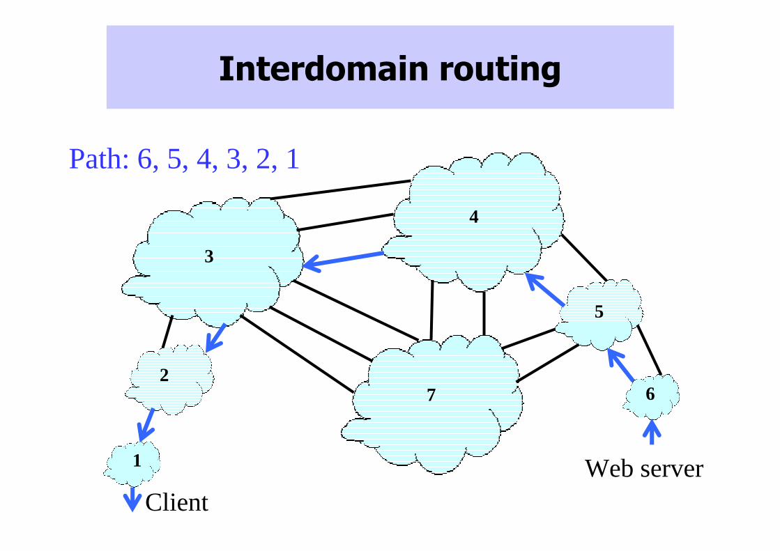
Interdomain routing
1
2
3
4
5
67
ClientWeb server
Path: 6, 5, 4, 3, 2, 1

Interdomain routing: the Border Gateway Protocol (BGP)
• ASes exchange information about which IP prefixes they can reach using path vector– Propagate (IP prefix, AS-path) pairs
• Policies configured by AS’s operator
– Path selection: which of paths to use?
– Path export: which neighbors to tell about path?
32 1
12.34.158.5
“12.34.158.0/24: path (2,1)” “12.34.158.0/24: path (1)”
data traffic data traffic

hierarchy #1 hierarchy #2 hierarchy #3
customer link
peer link
Types of AS relationships
Provider-customer: customer pays provider money to transit traffic
Peer link: ISPs form link out of mutual benefit, typically no money is exchanged

hierarchy #1 hierarchy #2 hierarchy #3
customer link
peer link
Policies between ISPs
• Example policies: peer, provider/customer• Also trust issues, security, scalability, traffic engineering
Prefer customer over peer routes
Do not export providerroutes to peers
Source Destination
hierarchy #1 hierarchy #2 hierarchy #3
customer link
peer link
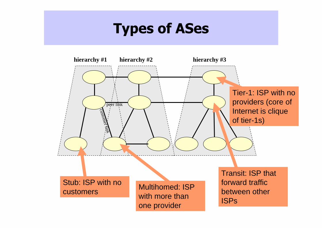
Types of ASes
Stub: ISP with no customers
Multihomed: ISP with more than one provider
Tier-1: ISP with no providers (core of Internet is clique of tier-1s)
Transit: ISP that forward traffic between other ISPs

Intra- vs. Inter-domain routing
• Run “Interior Gateway Protocol” (IGP) within ISPs
– OSPF, IS-IS, RIP
• Use “Border Gateway Protocol” (BGP) to connect ISPs
– To reduce costs, peer at exchange points (AMS-IX, MAE-EAST)
AT&T
Sprint
BGP session
source
dest

How inter- and intra- domain routing work together
Border routerInternal router
1. Provide internal reachability (IGP)2. Learn routes to external destinations (eBGP)3. Distribute externally learned routes internally (iBGP )4. Select closest egress (IGP)
62
4 9 2
13
3

How Ethernet and Intra-domain routing work together
IP subnet ==
Ethernet
broadcast
domain
(LAN or VLAN)
R
R
R
Current practice: a hybrid architecture comprised o f small Ethernet-based IP subnets connected by router s
R
R
R
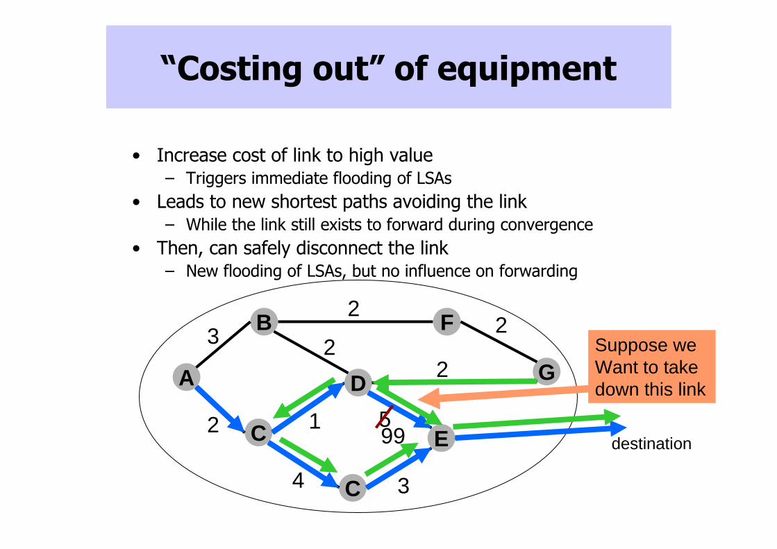
“Costing out” of equipment
• Increase cost of link to high value– Triggers immediate flooding of LSAs
• Leads to new shortest paths avoiding the link– While the link still exists to forward during convergence
• Then, can safely disconnect the link– New flooding of LSAs, but no influence on forwarding
B F
C
DA G
destination
C
E
32
22
2
51
34
2 99
Suppose we Want to take down this link

Naming and Addressing

Roadmap
• Addresses
– Assignment: CIDR, DHCP
– Translation: ARP, NAT
– Host mobility
• Names
– Translation to addresses
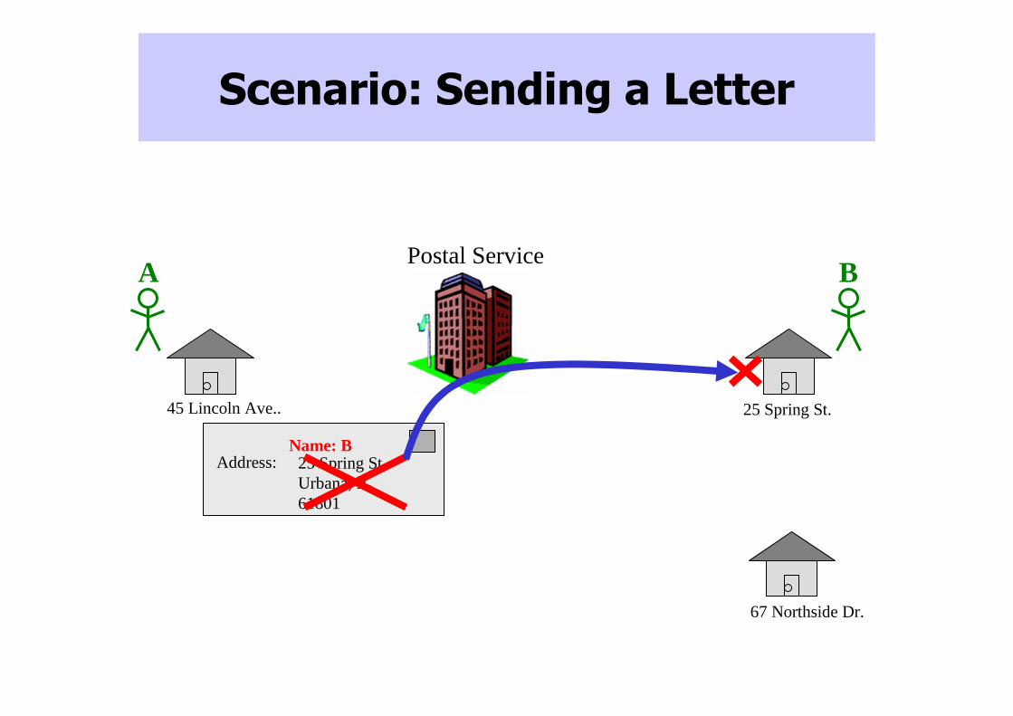
Postal Service
Scenario: Sending a Letter
25 Spring St. Urbana, IL 61801
Address:
45 Lincoln Ave.. 25 Spring St.
67 Northside Dr.
Name: B
A B

Scenario: Address Allocation
45 Lincoln Ave.. 25 Spring St.
61801
61802
61820A B
25 Spring St. Urbana, IL61802
Address:Name: B

Postal Service
Scenario: Access Control
25 Spring St.
67 Northside Dr.
“Inspect mail to 25 Spring St.”
45 Lincoln Ave..
C
D
25 Spring St. Urbana, IL61801
Address: 67 NorthsideDr. Urbana, IL 61801
Address:Name: C
Name: C

How Routing Works Today
• Each node has an address• Goal: find path to destination
Send(msg,Q)
B
J
S
K
Q
F
V
X
A

Area 1
Area 2
Area 4
Area 3
Scaling Requires Aggregation
• Pick addresses that depend on location• Aggregation provides excellent scaling properties• Key is topology-dependent addressing!
B
J
S
K
Q
F
V
X
A
1.1 1.2
2.12.2
4.2
4.1
3.33.2
3.1

IPv4 Address Model
• Properties– 32 bits, often written in dotted decimal notation (e.g.
72.14.205.147)
– Maps to logically unique network adaptor• Exceptions: NAT, load balancing servers
– Assigned based on position in topology• Simplifies routing
• Routers advertise IP prefixes– Aggregated blocks of IP addresses
– Used to reduce router state requirements
– Written in form network/subnet (e.g. 72.14.0.0/16) or with number/mask (e.g. 72.14.0.0/255.255.0.0)

Assigning IPv4 addresses
• Allocation: IANA � regional registries (eg. ARIN) �ISPs � ISP’s customers (eg. ISPs or enterprises)
• Pre-1993: Classful addressing
• Downside of classful addressing:
– Wasted address space
– Renumbering is time consuming and can interrupt service
Host (24 bits)0 Network (7 bits)
Network (14 bits)
1 1 0
1 0
Network (21 bits)
Host (16 bits)
Host (8 bits)
Class A:
Class B:
Class C:

CIDR
• Current approach: Classless Inter-Domain Routing (CIDR)– Allows variable-length classes– When two alternatives, route to longer prefix match
• Subnetting– Share one address (network number) across multiple physical
networks
• Supernetting/Aggregation– Aggregate multiple addresses (network numbers) for one physical
network
• Downsides:– Supernetting often disabled to avoid unintended side effects,
bloating routing tables– Multihomed sites don’t benefit from supernetting

Longest prefix match forwarding
• Multiple prefixes may “cover” the packet’s destination
– Used for load-balancing, failover
– Router identifies longest-matching prefix, sends to corresponding interface
4.0.0.0/84.83.128.0/1712.0.0.0/812.34.158.0/24126.255.103.0/24
12.34.158.5
destination
forwarding table
Serial0/0.1
outgoing link

CS/ECE 438 Robin Kravets and Matt Caesar, UIUC - Spring 2009
84
CIDR
• Allows hierarchical development– Assign a block of addresses to a regional provider
• Ex: 128.0.0.0/9 to BARRNET
– Regional provider subdivides address and hands out block to sub-regional providers• Ex: 128.132.0.0/16 to Berkeley
– Sub-regional providers can divide further for smaller organizations• Ex: 128.132.32.0/1 to Berkeley Computer Science
Department

CS/ECE 438 Robin Kravets and Matt Caesar, UIUC - Spring 2009
85
Subnetting
• Simple IP– All hosts on the same network must have the same
network number
• Assumptions– Subnets are close together
• Look like one network to distant routers
• Idea– Take a single IP network number– Allocate the IP addresses to several physical networks
(subnets)
• Subnetting– All hosts on the same network must have the same subnet
number

CS/ECE 438 Robin Kravets and Matt Caesar, UIUC - Spring 2009
86
Subnet Example
• Solution
– Partition the 65,536 address in the class B network
• 256 subnets each with 256 addresses
• Subnet mask: 255.255.255.0
– If 135.104.5.{1,2,3} are all on the same physical network reachable from router 135.105.4.1
• There only needs to be one routing entry for 135.104.5.* pointing to 135.105.4.1 as next hop

IPv4 Address Translation support
• IP addresses to LAN physical addresses
• Problem– An IP route can pass through many physical networks
– Data must be delivered to destination’s physical network
– Hosts only listen for packets marked with physical interface names• Each hop along route
• Destination host
TCP
IP IP
TCP
IP
FDDI FDDIETHETH

IP to Physical Address Translation
• Hard-coded– Encode physical address in IP address– Ex: Make IP address equal to lower 32 bits of Ethernet
address.– Problems:
• Uniqueness, hard to associate address with topology
• Fixed table– Maintain a central repository and distribute to hosts.– Problems:
• Bottleneck for queries and updates
• Solution: Automatically generated table– Use ARP to build table at each host– Use timeouts to clean up table

ARP: Address Resolution Protocol
• Check ARP table for physical address• If address not present
– Broadcast an ARP query, include querying host’s translation– Wait for an ARP response
• Upon receipt of ARP query/response– Targeted host responds with address translation– If address already present
• Refresh entry and reset timeout
– If address not present• Add entry for requesting host• Ignore for other hosts
• Timeout and discard entries after O(10) minutes
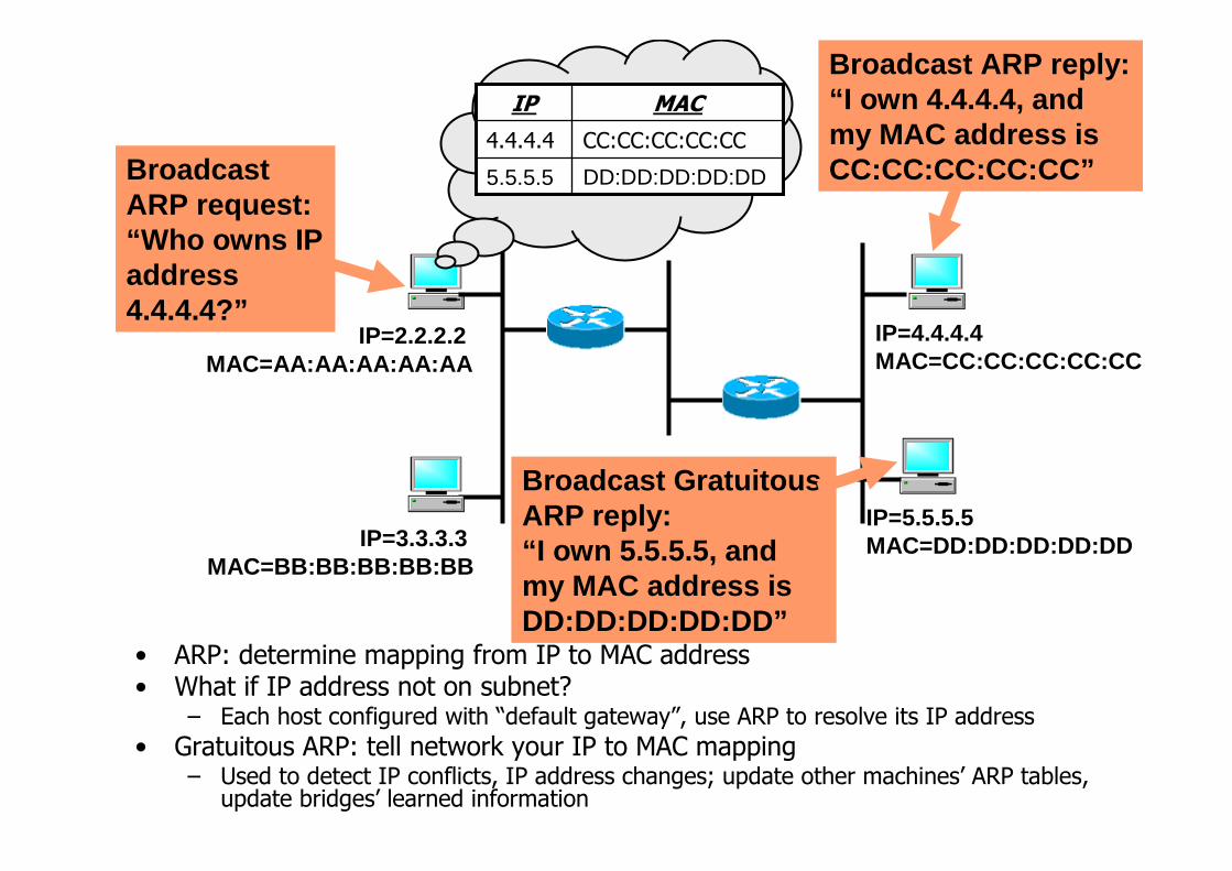
• ARP: determine mapping from IP to MAC address• What if IP address not on subnet?
– Each host configured with “default gateway”, use ARP to resolve its IP address
• Gratuitous ARP: tell network your IP to MAC mapping– Used to detect IP conflicts, IP address changes; update other machines’ ARP tables,
update bridges’ learned information
Broadcast ARP request:“Who owns IP address 4.4.4.4?”
IP=2.2.2.2 MAC=AA:AA:AA:AA:AA
IP=3.3.3.3 MAC=BB:BB:BB:BB:BB
IP=4.4.4.4 MAC=CC:CC:CC:CC:CC
Broadcast ARP reply:“I own 4.4.4.4, and my MAC address is CC:CC:CC:CC:CC”
IP=5.5.5.5MAC=DD:DD:DD:DD:DD
Broadcast GratuitousARP reply:“I own 5.5.5.5, and my MAC address is DD:DD:DD:DD:DD”
CC:CC:CC:CC:CC4.4.4.4
MACIP
DD:DD:DD:DD:DD5.5.5.5

Host Configuration
• Plug new host into network– Host needs an IP address
– Host must also
• Send packets out of physical (direct) network
• Thus needs physical address of “gateway”router

Dynamic Host Configuration Protocol (DHCP)
• A simple way to automate host configuration
– Network administrator does not need to enter host IP address by hand
– Good for large and/or dynamic networks
• New machine sends request to DHCP server for assignment and information

Dynamic Host Configuration Protocol (DHCP)
• Server receives– Directly if new machine given server’s IP address– Through broadcast if on same physical network– Or via DHCP relay nodes
• Forward requests onto the server’s physical network
• Server assigns IP address and provides other info• Can be made secure
– Present signed request or just a “valid” physical address
• Remaining challenge: configuring DHCP servers– Need to ensure consistency across servers, between servers
and network, address assignment across routers– But simpler than directly managing end hosts

DHCP
DHCP Server
Host AHost A
broadcasts DHCPDISCOVER
messageHost A
broadcasts DHCP request
Host B
DHCP Server
DHCP Relay
Other Networks
Other Networks
Relay unicastsDHCP request
to serverServer
responds with host’s IP address
Robin Kravets and Matt Caesar, UIUC - Spring 2009
95
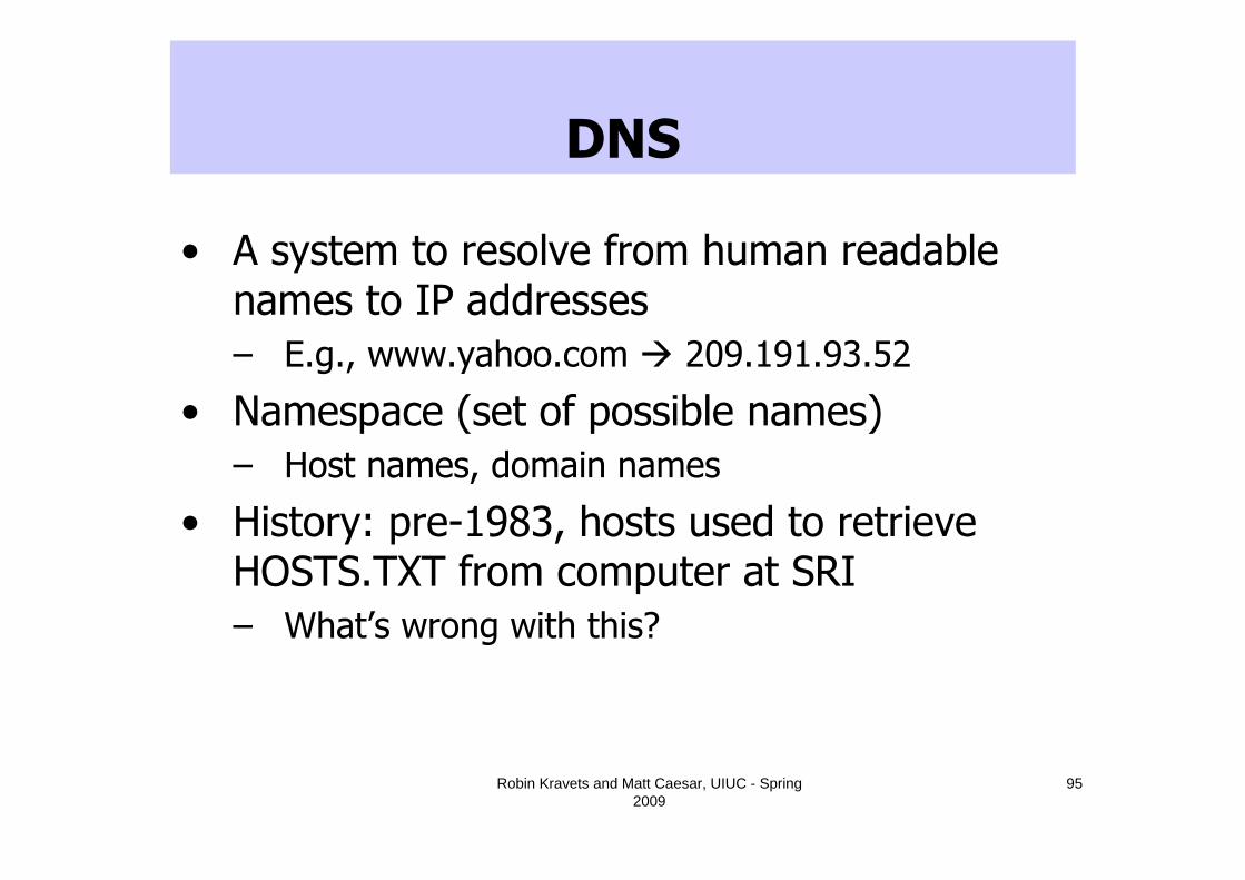
DNS
• A system to resolve from human readable names to IP addresses
– E.g., www.yahoo.com � 209.191.93.52
• Namespace (set of possible names)
– Host names, domain names
• History: pre-1983, hosts used to retrieve HOSTS.TXT from computer at SRI
– What’s wrong with this?

Robin Kravets and Matt Caesar, UIUC - Spring 2009
96
Comparison of domain names and IP addresses
• Internet domain names
– Human readable
– Variable length
– Hierarchy used to ease administrative effort in allocating names
• IP Addresses
– Easily handled by routers
– Fixed length
– Hierarchy used to reduce routing table size

Robin Kravets and Matt Caesar, UIUC - Spring 2009
97
DNS – Name Space
• Domain name hierarchy– Structure
• Period separated identifiers
• Host name first
• Each subsequent component is a larger group
au jp com gov org edu biz info
ibm yahoo uiuc ucla
cs ece

Robin Kravets and Matt Caesar, UIUC - Spring 2009
98
DNS – Name Space
• Implementation
– Each identifier (after host name) denotes a zone
– Translation for each zone supported by 2+ name servers
au jp com gov mil edu net org
ibm yahoo uiuc ucla
cs ece

Robin Kravets and Matt Caesar, UIUC - Spring 2009
99
DNS - Bindings
• Name servers maintain– Collection of resource records (5-tuples)
• (name, value, type, class, TTL)
• Type is how name/value should be interpreted– type=A:
• name=full domain name; value=IP addr• Implements name-to-address mapping
– type=NS: • name=zone name; value=zone name server’s domain name• Value is nameserver that can resolve this particular zone• Root nameserver has an NS record for each TLD
– type=CNAME: – type=MX:

Robin Kravets and Matt Caesar, UIUC - Spring 2009
100
DNS - Bindings
• Name servers maintain– Collection of resource records (5-tuples)
• (name, value, type, class, TTL)
• Type is how name/value should be interpreted– type=A: – type=NS: – type=CNAME:
• name=domain name alias; value=canonical domain name for host
• Can create multiple aliases for a single physical host• E.g., ftp.cs.uiuc.edu, www.cs.uiuc.edu point to different ports on srv1.cs.uiuc.edu
– type=MX: • name=zone name; value=maildrop host’s full domain name• Value field gives the domain name for a host that is running a mail server for the specified domain

Robin Kravets and Matt Caesar, UIUC - Spring 2009
101
DNS - Bindings
• Resource Record
– Class
• Generally set to IN (= Internet)
• Allows use of DNS for other purposes
• Rarely used
– TTL
• How long resource is valid (in seconds)
• Used for caching, eviction after TTL expiry

Robin Kravets and Matt Caesar, UIUC - Spring 2009
102
DNS - Bindings
• Example resource records at a root name server< arizona.edu, telcom.arizona.edu, NS, IN >
< telcom.arizona.edu, 128.196.128.233, A, IN >
< bellcore.com, thumper.bellcore.com, NS, IN >
< thumper.bellcore.com, 128.96.32.20, A, IN >

Robin Kravets and Matt Caesar, UIUC - Spring 2009
103
DNS - Bindings
• Examples of resource records at Arizona’s name server< cs.arizona.edu, optima.cs.arizona.edu, NS, IN >
< optima.cs.arizona.edu, 192.12.69.5, A, IN >
< ece.arizona.edu, helios.ece.arizona.edu, NS, IN >
< helios.ece.arizona.edu, 128.196.28.166, A, IN >
< jupiter.physics.arizona.edu, 128.196.4.1, A, IN >
< saturn.physics.arizona.edu, 128.196.4.2, A, IN >
Robin Kravets and Matt Caesar, UIUC - Spring 2009
104
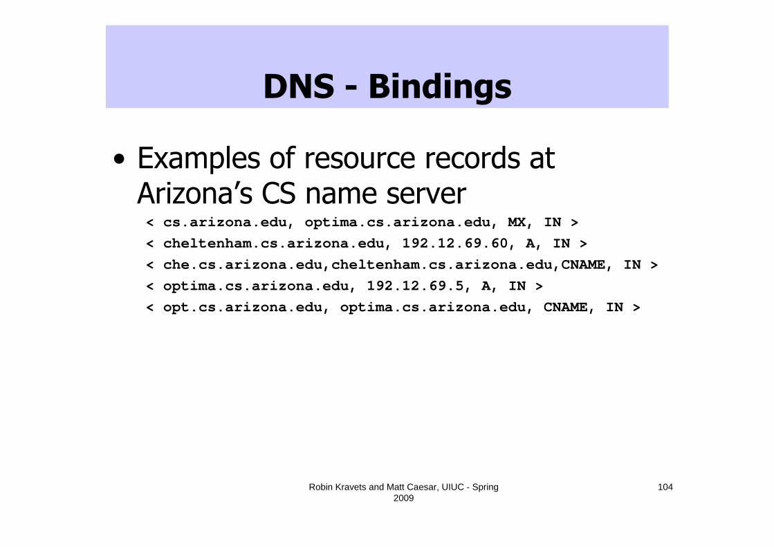
DNS - Bindings
• Examples of resource records at Arizona’s CS name server< cs.arizona.edu, optima.cs.arizona.edu, MX, IN >
< cheltenham.cs.arizona.edu, 192.12.69.60, A, IN >
< che.cs.arizona.edu,cheltenham.cs.arizona.edu,CNAME, IN >
< optima.cs.arizona.edu, 192.12.69.5, A, IN >
< opt.cs.arizona.edu, optima.cs.arizona.edu, CNAME, IN >
Robin Kravets and Matt Caesar, UIUC - Spring 2009
105
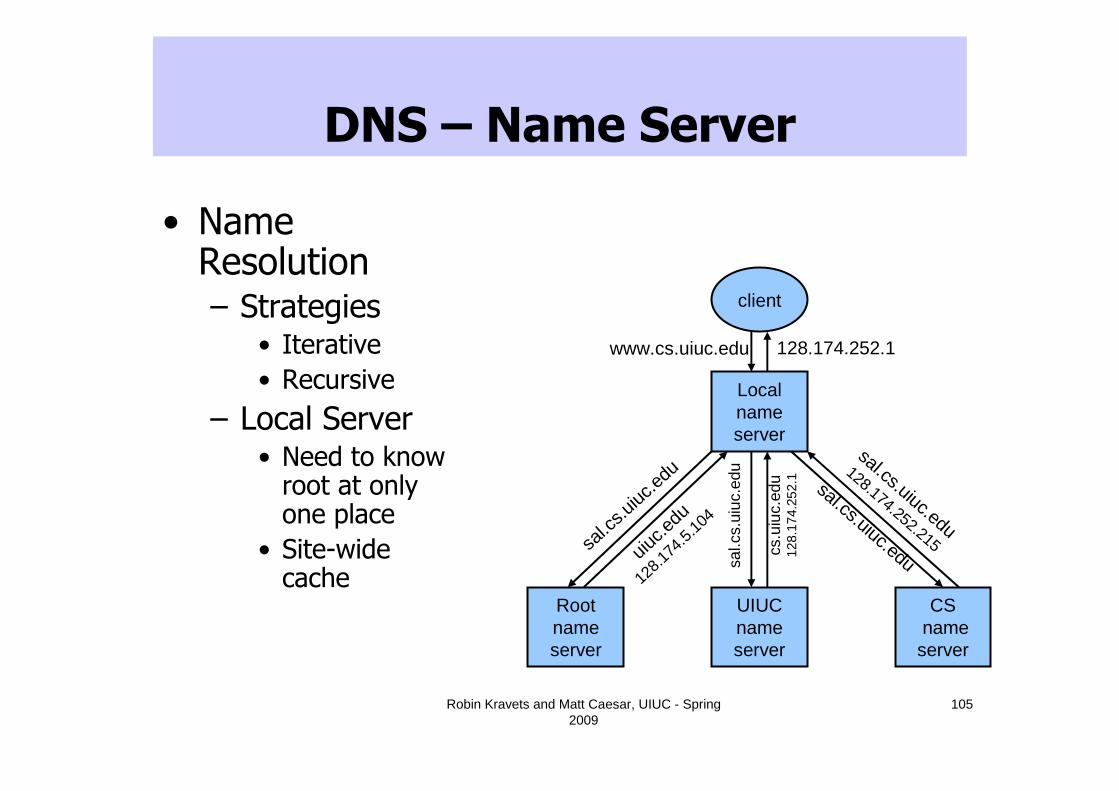
DNS – Name Server
• Name Resolution– Strategies
• Iterative
• Recursive
– Local Server• Need to know root at only one place
• Site-wide cache
client
Local name server
CSname
server
UIUC name server
Root name server
www.cs.uiuc.edu
sal.c
s.uiuc
.edu
uiuc.e
du
128.1
74.5
.104
sal.c
s.ui
uc.e
du
cs.u
iuc.
edu
128.
174.
252.
1
sal.cs.uiuc.edu
sal.cs.uiuc.edu
128.174.252.215
128.174.252.1

DNS: Domain Name System
• Internet hosts
– IP address (32 bit)
• Used for addressing datagrams
– Host name (e.g., www.yahoo.com)
• Used by humans
• DNS: provides translation between host name and IP address
– Distributed database implemented in hierarchy of many name servers
– Distributed for scalability & reliability
106

DNS
• DNS services
– Hostname to IP address translation
– Host aliasing
• Canonical, alias names
– Mail server aliasing
– Load distribution
• Replicated Web servers: set of IP addresses for one canonical name
• Why not centralize DNS?
– Single point of failure
– Traffic volume
– Distant centralized database
– Maintenance
• Doesn’t scale!
107

Distributed, Hierarchical Database
• Client wants IP for www.amazon.com– Client queries a root server to find com DNS server
– Client queries com DNS server to get amazon.com DNS server
– Client queries amazon.com DNS server to get IP address for www.amazon.com
108
Root DNS Servers
com DNS servers org DNS servers edu DNS servers
uiuc.eduDNS servers
umass.eduDNS servers
yahoo.comDNS servers
amazon.comDNS servers
pbs.orgDNS servers

DNS: Root Name Servers
• Contacted by local name server that can not resolve name, Contacts/redirects to authoritative name server if mapping not known
• Only 2% of queries reaching root are legitimate (incorrect caching is 75%, 7% were lookups for IPs as domain names, 12.5% were for unknown TLDs)
109
13 root name servers worldwide
b USC-ISI Marina del Rey, CAl ICANN Los Angeles, CA
e NASA Mt View, CAf Internet Software C. Palo Alto, CA (and 36 other locations)
i Autonomica, Stockholm (plus 28 other locations)
k RIPE London (also 16 other locations)
m WIDE Tokyo (also Seoul, Paris, SF)
a Verisign, Dulles, VAc Cogent, Herndon, VA (also LA)d U Maryland College Park, MDg US DoD Vienna, VAh ARL Aberdeen, MDj Verisign, ( 21 locations)
TLD and Authoritative Servers
• Top-level domain (TLD) servers– Responsible for com, org, net, edu, etc, and all top-level
country domains uk, fr, ca, jp.• Network Solutions maintains servers for com TLD
• Educause for edu TLD
• Authoritative DNS servers
– Organization’s DNS servers
– Provide authoritative hostname to IP mappings for organization’s servers (e.g., Web, mail).
– Can be maintained by organization or service provider
110

111
Local Name Server
• When host makes DNS query, query is sent to its local DNS server
– Acts as proxy, forwards query into hierarchy
– Uses caching to reduce lookup latency for commonly searched hostnames

DNS name resolution example
• Host at cs.uiuc.edu wants IP address for gaia.cs.umass.edu
• Iterated query– Contacted server replies
with name of server to contact
– “I don’t know this name, but ask this server”
– Alternative: recursive queries (typically used only for local DNS, as requires state to be stored)
requesting hostcs.uiuc.edu
gaia.cs.umass.edu
root DNS server
local DNS serverdns.uiuc.edu
1
23
4
5
6authoritative DNS server
78
TLD DNS server
dns.cs.umass.edu

DNS: Caching
• Once (any) name server learns mapping, it caches mapping
– Cache entries timeout (disappear) after some time
– TLD servers typically cached in local name servers
• Thus root name servers not often visited
113
Robin Kravets and Matt Caesar, UIUC - Spring 2009
114
Domain Name Service (DNS)
• Large scale dynamic, distributed application– Replaced Network Information Center (NIC)
• RFC 1034 and 1035
• Outline– Comparison of domain names and addresses
– Domain name hierarchy
– Implementation of hierarchy
– Name resolution

Robin Kravets and Matt Caesar, UIUC - Spring 2009
115
Network Address Translation (NAT)
• Deals with problem of limited address space– Use locally unique addresses inside an organization
– For communication outside the organization, use a NAT box• Translate from locally unique address to globally unique NAT
address
• Saves addresses if only a few hosts are ever communicating outside the organization
• Problem– Breaks IP service model
– Lots of debate over whether this is a “permanent” or “temporary” solution
NAT: Network Address Translation
• Change IP Headers
– IP addresses (and possibly port numbers) of IP datagrams are replaced at the boundary of a private network
– Enables hosts on private networks to communicate with hosts on the Internet
– Run on routers that connect private networks to the public Internet
116

NAT: Network Address Translation
• Outgoing packet
– Source IP address (private IP) is replaced by one of the global IP addresses maintained by the NAT router
• Incoming packet
– Destination IP address (global IP of the NAT router) is replacedby the appropriate private IP address

NAT: Network Address Translation
10.0.0.1
10.0.0.2
10.0.0.3
10.0.0.4
138.76.29.7
local network(e.g., home network)
10.0.0.*
rest ofInternet
Datagrams with source or destination in this networkhave 10.0.0.* address for
source, destination (as usual)
All datagrams leaving localnetwork have same single source
NAT IP address: 138.76.29.7,different source port numbers

NAT: Network Address Translation
• Motivation: local network uses just one IP address as far as outside word is concerned
– No need to be allocated range of addresses from ISP
• Just one IP address is used for all devices
– Can change addresses of devices in local network without notifying outside world
– Can change ISP without changing addresses of devices in local network
– Devices inside local net not explicitly addressable, visible by outside world (a security plus).

NAT: Network Address Translation
• Outgoing datagrams
– replace (source IP address, port #) of every outgoing datagram with (NAT IP address, new port #)
• Remote clients/servers respond using (NAT IP address, new port #) as destination addr
• Cache (in NAT translation table)
– Every (source IP address, port #) to (NAT IP address, new port #) translation pair
• Incoming datagrams
– Replace (NAT IP address, new port #) in dest fields of every incoming datagram with corresponding (source IP address, port #) stored in NAT table

NAT: Network Address Translation
10.0.0.1
10.0.0.2
10.0.0.3
S: 10.0.0.1, 3345D: 128.119.40.186, 80
1
10.0.0.4
138.76.29.7
1: host 10.0.0.1 sends datagram to 128.119.40, 80
NAT translation tableWAN side addr LAN side addr
138.76.29.7, 5001 10.0.0.1, 3345…… ……
S: 128.119.40.186, 80 D: 10.0.0.1, 3345 4
S: 138.76.29.7, 5001D: 128.119.40.186, 802
2: NAT routerchanges datagramsource addr from10.0.0.1, 3345 to138.76.29.7, 5001,updates table
S: 128.119.40.186, 80 D: 138.76.29.7, 5001 3
3: Reply arrivesdest. address:138.76.29.7, 5001
4: NAT routerchanges datagramdest addr from138.76.29.7, 5001 to 10.0.0.1, 3345
121
NAT: Network Address Translation
• Address Pooling
– Corporate network has many hosts
– Only a small number of public IP addresses
• NAT solution
– Manage corporate network with a private address space
– NAT, at boundary between corporate network and public Internet, manages a pool of public IP addresses
– When a host from corporate network sends an IP datagram to a host in public Internet, NAT picks a public IP address from the address pool, and binds this address to the private address of the host
122
NAT: Network Address Translation
• IP masquerading– Single public IP address is mapped to multiple hosts in a
private network
• NAT solution– Assign private addresses to the hosts of the corporate
network
– NAT device modifies the port numbers for outgoing traffic
– Modifying the IP header by changing the IP address requires that NAT boxes recalculate the IP header checksum
– Modifying port number requires that NAT boxes recalculate TCP checksum
123
NAT: Network Address Translation
• Load balancing
– Balance the load on a set of identical servers, which are accessible from a single IP address
• NAT solution
– Servers are assigned private addresses
– NAT acts as a proxy for requests to the server from the public network
– NAT changes the destination IP address of arriving packets to one of the private addresses for a server
– Balances load on the servers by assigning addresses in a round-robin fashion
124

NAT: Network Address Translation
• 16-bit port-number field
– 60,000 simultaneous connections with a single LAN-side address!
• End-to-end connectivity
– NAT destroys universal end-to-end reachability of hosts on the Internet
– A host in the public Internet often cannot initiate communication to a host in a private network
– The problem is worse, when two hosts that are in different private networks need to communicate with each other
125

NAT: Network Address Translation
• IP address in application data
– Applications often carry IP addresses in the payload of the application data
– No longer work across a private-public network boundary
– Hack: Some NAT devices inspect the payload of widely used application layer protocols and, if an IP address is detected in the application-layer header or the application payload, translate the address according to the address translation table
126

Roadmap
• Addresses
– Assignment: CIDR, DHCP
– Translation: ARP, NAT
• Names
– Translation to addresses

CS/ECE 438 Robin Kravets and Matt Caesar, UIUC - Spring 2009
128
Routing For Mobile Hosts
• Scenarios– Mobile hosts, fixed infrastructure
• Cellular networks
• 802.11 enterprise networks
– Mobile hosts, dynamic infrastructure• Ad hoc networks
• Problem– How can mobility be supported in view of the fact that a
portion of an IP address is a network address?
– Solution: Mobile IP

CS/ECE 438 Robin Kravets and Matt Caesar, UIUC - Spring 2009
129
IP Address Problem
• Internet hosts/interfaces are identified by IP address– Domain name service translates host name to IP
address– IP address identifies host/interface and locates its
network– Mixes naming and location
• Moving to another network requires different network address– But this would change the host’s identity– How can we still reach that host?

Routing for Mobile Hosts with Mobile IP
Mobile Host
Addr=A
ForeignAgent
HomeAgent
Mobile Host
Addr=B
Sending Host
CS/ECE 438 Robin Kravets and Matt Caesar, UIUC - Spring 2009
131
Why Mobile IP?
• Goal– IP-based protocol which allows network
connectivity across host movement
• Features– Doesn’t require global changes to deployed
router software, etc.
– Compatible with large installed base of IPv4 networks/hosts
– Confines changes to mobile hosts and a few support hosts which enable mobility

CS/ECE 438 Robin Kravets and Matt Caesar, UIUC - Spring 2009
132
Basic Mobile IP
• Features– Transparent routing of packets to a
mobile host
– No modification of existing routers or non-mobility supporting hosts
• Problem– Indirect routing places unnecessary
burden on the internet and significant increases latency

CS/ECE 438 Robin Kravets and Matt Caesar, UIUC - Spring 2009
133
Components
• Mobile Host (MH):
– Assigned a unique home address within its home network
• Corresponding Hosts (CH):
– Other hosts communicating with the MH
– Always use MH’s home address

CS/ECE 438 Robin Kravets and Matt Caesar, UIUC - Spring 2009
134
Routing for Mobile Hosts
• Home Agent (HA):– An agent on the MH’s home network
– Maintains registry of MH’s current location
– Mobility binding is the connection between the MH’s home address and care-of-address (MH’s remote address)
– Each time the MH establishes a new care-of-address, it must register with its HA
• Foreign Agent (FA):– An agent on the MH’s local network
– Maintains a mapping from the MH’s home address to its care-of-address

CS/ECE 438 Robin Kravets and Matt Caesar, UIUC - Spring 2009
135
Issues
• Scenario– CH sends packet to home network
• Challenges– How does the MH get a local IP address?
– How can a mobile host tell where it is?
– How does the HA intercept a packet that is destined for the MH?
– How does the HA then deliver the packet to the FA?
– How does the FA deliver the packet to the MH?

CS/ECE 438 Robin Kravets and Matt Caesar, UIUC - Spring 2009
136
Basic Mobile IP
HAFA
MH: Mobile host
HA: Home AgentFA: Foreign Agent
CH: Correspondent HostCH
128.174.5.x171.64.14.x
MH
128.174.5.58MH
128.174.5.58171.64.14.14
Registration171.64.14.14
CoA: Care-of-Address

CS/ECE 438 Robin Kravets and Matt Caesar, UIUC - Spring 2009
137
Basic Mobile IP
HAFA
CH
128.174.5.x171.64.14.x
MH
128.174.5.58171.64.14.14
Registration171.64.14.14
� Agent Discovery� Assignment of CoA� CoA Registration� Packet Tunneling

CS/ECE 438 Robin Kravets and Matt Caesar, UIUC - Spring 2009
138
Addressing
• How does the mobile host get a remote IP address?– Listen for router advertisements
– Use DHCP
– Manual assignment
• Assigning care-of-address– MH discovers foreign agent (FA) using an agent discovery
protocol
– MH registers with FA and FA’s address becomes MH’s care-of-address
– MH obtains a temporary IP address from FA or via DHCP-like procedures

CS/ECE 438 Robin Kravets and Matt Caesar, UIUC - Spring 2009
139
Location
• How can a mobile host tell where it is?
– Am I at home?
– Am I visiting a foreign network?
– Have I moved?
– Again, listen for router advertisements
– Put network interface into promiscuous mode and watch traffic

CS/ECE 438 Robin Kravets and Matt Caesar, UIUC - Spring 2009
140
Agent Discovery
• How can a mobile host tell where it is?
– Extension of ICMP protocol
– Allows MH to detect when it has moved from one network to another, or to home
– FA Periodically broadcasts agent advertisement message
FA
171.64.14.x
MH
128.174.5.58
CS/ECE 438 Robin Kravets and Matt Caesar, UIUC - Spring 2009
141
Agent Discovery
• MH determines a suitable FA (or its HA) with which to register
• If MA has not received a broadcast for a period of time, it can send an agent solicitation message

CS/ECE 438 Robin Kravets and Matt Caesar, UIUC - Spring 2009
142
Packet Delivery
• How does the HA intercept a packet that is destined for the MH?
• While MH in foreign location– HA intercepts all packets for MH
• Using proxy ARP
– HA tunnels all packets to FA• IPIP - “IP within IP”
• Upon receipt of an IP datagram– Packet is encapsulated in an IP packet of type IPPROTO_IPIP
and sent to FA
– FA strips IPIP header and sends packet to MH using local IP address
– FA strips packet and forwards to MH

CS/ECE 438 Robin Kravets and Matt Caesar, UIUC - Spring 2009
143
Registration
• MA must register with FA and tell HA its new care-of-address
– MH sends registration request message to FA
– FA forwards request to HA
– HA returns registration reply message to FA
– FA forwards reply to MH
• Registration may have a set lifetime

CS/ECE 438 Robin Kravets and Matt Caesar, UIUC - Spring 2009
144
Care-of-Address Registration
HA
FA
128.174.5.x
171.64.14.x
MH
128.174.5.58
Registration Request
Request Relay
Registration Reply
Reply Relay
171.64.14.14128.174.5.58
Timeout
171.64.14.14

CS/ECE 438 Robin Kravets and Matt Caesar, UIUC - Spring 2009
145
Network Layer
• IPIP - “IP within IP”
– Tunnel IP datagrams from one subnet to another
– Upon receipt of an IP datagram
• Packet is encapsulated in an IP packet of type IPPROTO_IPIP and sent to remote MSS
• Remote MSS strips IPIP header and sends packet to MH using “real” IP address

CS/ECE 438 Robin Kravets and Matt Caesar, UIUC - Spring 2009
146
Tunneling
HA
FA
128.174.5.x
171.64.14.x
MH
128.174.5.58
128.174.5.58
…
128.174.5.58
…
171.64.14.14128.174.5.58
…
CH
171.64.14.14

CS/ECE 438 Robin Kravets and Matt Caesar, UIUC - Spring 2009
147
Tunneling Using IP-in-IP Encapsulation
VersFragment OffsetFlagsIP Identification
Total LengthTOSIHL
TTL IP in IP IP Header Checksum
Tunnel Source IP AddressCare-of-Address
VersFragment OffsetFlagsIP Identification
Total LengthTOSIHL
TTL Orig. Protocol IP Header Checksum
Original Source IP AddressIP Address of Mobile Host
TCP/UDP/etc
0 4 8 16 19 31

CS/ECE 438 Robin Kravets and Matt Caesar, UIUC - Spring 2009
148
Tunneling Using Minimal Tunneling Protocol
VersFragment OffsetFlagsIP Identification
Total LengthTOSIHL
TTL Min Encap IP Header Checksum
Tunnel Source IP AddressCare-of-Address
Tunnel Header ChecksumS
Original Source IP Address (only present if S is set)
IP Address of Mobile Host
TCP/UDP/etc
0 4 8 16 19 31
Orig. Protocol

CS/ECE 438 Robin Kravets and Matt Caesar, UIUC - Spring 2009
149
Triangle Routing Problem
HA
CH
MH
• Routing through HA increases latency

CS/ECE 438 Robin Kravets and Matt Caesar, UIUC - Spring 2009
150
Route Optimization
• Basic Mobile IP routes all packets for a MH through its home network and HA
– Limits performance
– Potential bottleneck
– Not scalable
• Solution
– Cache MH location and care-of address
CS/ECE 438 Robin Kravets and Matt Caesar, UIUC - Spring 2009
151
Location Caching
• Binding Cache
– Maintains location information about MHs
– Binding cache entry
• Packet is tunneled directly to MH’s care-of-address
– No binding cache entry
• Packet is sent to MH’s HA
• HA sends new entry
– Can support networks with no Mobile IP by putting binding cache in router

CS/ECE 438 Robin Kravets and Matt Caesar, UIUC - Spring 2009
152
Binding Cache
HA
FA
128.174.5.x
171.64.14.x
MH
128.174.5.58
128.174.5.58
…
128.174.5.58
…
171.64.14.14128.174.5.58
…
CH
Binding update171.64.14.14
171.64.14.14128.174.5.58
Timeout
171.65.14.14
…

Based on a Tutorial by
Nitin Vaidya
Ad Hoc Networks
CS/ECE 438 © Robin Kravets, M. Caesar, UIUC - Spring 2007
153

CS/ECE 438 © Robin Kravets, M. Caesar, UIUC - Spring 2007
154
Routing in Ad Hoc Networks
• Ad hoc network
– A collection of mobile nodes with wireless interfaces that form a temporary network without the aid of any established or centralized administration
Client Server Network: fixed infrastructure
Ad Hoc Network: no servers or
access points

CS/ECE 438 © Robin Kravets, M. Caesar, UIUC - Spring 2007
155
Mobile Ad Hoc Networks
• Formed by wireless hosts which may be mobile
• Without (necessarily) using a pre-existing infrastructure
• Routes between nodes may potentially contain multiple hops

CS/ECE 438 © Robin Kravets, M. Caesar, UIUC - Spring 2007
156
Multi-Hop Wireless
• May need to traverse multiple links to reach a destination

CS/ECE 438 © Robin Kravets, M. Caesar, UIUC - Spring 2007
157
Multi-Hop Wireless
• Mobility
– Mobile Ad Hoc Networks (MANET)
– Mobility causes route changes

CS/ECE 438 © Robin Kravets, M. Caesar, UIUC - Spring 2007
158
Why Ad Hoc Networks ?
• Ease of deployment
• Speed of deployment
• Decreased dependence on infrastructure

CS/ECE 438 © Robin Kravets, M. Caesar, UIUC - Spring 2007
159
Challenges
• Limited wireless transmission range
• Broadcast nature of the wireless medium
– Hidden terminal problem
• Packet losses due to transmission errors
• Mobility-induced route changes
• Mobility-induced packet losses
• Battery constraints
• Potentially frequent network partitions
• Ease of snooping on wireless transmissions

CS/ECE 438 © Robin Kravets, M. Caesar, UIUC - Spring 2007
160
Why is Routing in MANET different ?
• Host mobility
– Link failure/repair due to mobility may have different characteristics than those due to other causes
• Rate of link failure/repair may be high when nodes move fast
• New performance criteria may be used
– Route stability despite mobility
– Energy consumption

CS/ECE 438 © Robin Kravets, M. Caesar, UIUC - Spring 2007
161
Routing in Ad Hoc Networks
• Periodic Protocols:– Driven by timer based mechanisms– Distance-Vector and Link-State protocols send periodic
routing advertisements– Link status detection is beacon-based
• Concerns:– Periodic updates waste bandwidth and power (especially if
nothing changes)– Topology changes may be too dynamic to be captured by
periodic updates– Routes may not work (some links may be unidirectional)– Shortest path may not be best path (signal strength,
energy consumption)

CS/ECE 438 © Robin Kravets, M. Caesar, UIUC - Spring 2007
162
Routing Protocols
• Proactive protocols
– Determine routes independent of traffic pattern
– Traditional link-state and distance-vector routing protocols are proactive
• Reactive (on-demand) protocols
– Maintain routes only if needed

CS/ECE 438 © Robin Kravets, M. Caesar, UIUC - Spring 2007
163
Routing in Ad Hoc Networks
• On-demand Protocols:
– Actions driven by data packets requiring delivery
– Obtain a route only when needed
– Link status detection performed only when forwarding data
– Allow new metrics
– Ex:
• Dynamic Source Routing Protocol (DSR)
• Ad Hoc On-Demand Distance Vector Protocol (AODV)

CS/ECE 438 © Robin Kravets, M. Caesar, UIUC - Spring 2007
164
Routing in Ad Hoc Networks
• On-demand Protocols
– Path/Route discovery
• used to set up forward and reverse paths
– Route table management
• Route tables are soft-state
• Performance Concerns
– Latency to set up route
– Overhead for route maintenance

CS/ECE 438 © Robin Kravets, M. Caesar, UIUC - Spring 2007
165
Trade-Off
• Latency of route discovery
– Proactive protocols
• May have lower latency since routes are maintained at all times
– Reactive protocols
• May have higher latency because a route from X to Y will be found only when X attempts to send to Y
CS/ECE 438 © Robin Kravets, M. Caesar, UIUC - Spring 2007
166
Trade-Off
• Overhead of route discovery/maintenance– Reactive protocols
• May have lower overhead since routes are determined only if needed
– Proactive protocols • Can (but not necessarily) result in higher overhead due
to continuous route updating
• Which approach achieves a better trade-off depends on the traffic and mobility patterns