lecture 9 10th march
TRANSCRIPT

8/12/2019 Lecture 9 10th March
http://slidepdf.com/reader/full/lecture-9-10th-march 1/14
Bevel gears have teeth shapedgenerally like ordinary spur
gears, except that the toothsurfaces are made up of conicalelements.
The teeth may be straight or
spiral Spiral teeth engagegradually (starting at one side,as with helical gears), a featureenabling them to operate moresmoothly and quietly.
Except for hypoid gears bevelgears are mounted on shaftshaving intersecting axes. Theshaft axes are usually, butnot necessarily, perpendicular.

8/12/2019 Lecture 9 10th March
http://slidepdf.com/reader/full/lecture-9-10th-march 2/14
When the pitch angle is equal to 90 it is called crown bevel gear
These bevel gears are mounted on shafts which are intersecting at
an angle that is more than 90 . Crown gear is equivalent to rack.
The pitch angle of a bevel gear is the angle of the pitch cone. It is ameasure of the amount of taper in the gear.
Bevels gears are classified on the basis of pitch angle
When the pitch angl e is less than 90 it is called external bevel gear.
Miter gears: Identical bevel gears are mounted on shafts that are
intersecting at right angles, pitch angle of both pinion and gear are 45 .
Pinion and gear have same dimensions(adde, ded, pcd no of teeth and
module) and rotate at same speed
When the pitch angle is more than 90 it is called internal bevel
gear
Teeth of bevel gears are cut on the inside of the pitch cone. In
this case, the pitch angle of internal gear is more than 90 and the
apex point is one the back side of the teeth on that gear. Theseinternal gears are used in planetary gear trains

8/12/2019 Lecture 9 10th March
http://slidepdf.com/reader/full/lecture-9-10th-march 3/14
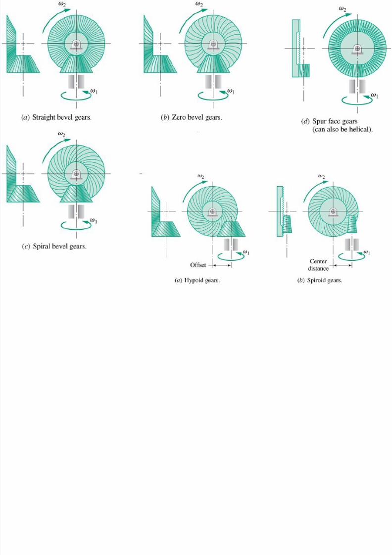
Straight bevel gears: Teeth elements are straight lines which converge into a common apex
point
Spiral bevel gears: Teeth elements are spiral curves which also converge into a common apex
pointSkew bevel gears: Shaft on which straight bevel gears are mounted are non parallel and non-
intersecting. Apex point of the pinion is offset with respect to that of gear
Hypoid gears: Similar to spiral bevel gears that are mounted on shafts which are non parallel and
non intersecting. Used in automobile differential which allow the drive shaft to place well belowthe centerline of the rear axle thereby lower the center of gravity of vehicle
Face gears: Consists of spur or helical pinion mating with a conjugate gear of disk form
8/12/2019 Lecture 9 10th March
http://slidepdf.com/reader/full/lecture-9-10th-march 4/14

8/12/2019 Lecture 9 10th March
http://slidepdf.com/reader/full/lecture-9-10th-march 5/14
The tooth dimensions are usually specified for thelarge end of the tooth. However, in calculatingbearing loads, central-section dimensions and forcesare used
The simplest type of bevel gear is the straight bevel gear. These gears are commonly used for transmitting power between intersecting shafts. Usually the shaft
angle is 90°, but it may be almost any angle. The gearsimpose both radial and thrust load on their bearing.
In contrast to the cylindrical pitch surfaces of spur and helical gears, the pitch surfaces of
meshing bevel gears are conical. When teeth are cut on the conical pitch surfaces they must be
tapered both in tooth thickness and height from a large tooth profile at one end to a smaller tooth
profile at the other end
Bevel gear teeth have profiles that closelyresemble an involute curve. The shape of astraight bevel gear tooth (in a section normal tothe tooth) closely approximates that of aninvolute spur gear

8/12/2019 Lecture 9 10th March
http://slidepdf.com/reader/full/lecture-9-10th-march 6/14
The practice of characterizing the size and shape of bevel gear teeth as those of an
imaginary spur gear appearing on the developed back cone corresponds to what is
known as Tredgold’s approximation
When intersecting shafts are
connected by gears, the pitch cones
(analogous to the pitch cylinders of
spur and helical gears) are tangent
along an element, with their apexes
at the intersection of the shafts. The
size and shape of the teeth are
defined at the large end, where they
intersect the back cones. Note that
the pitch cone and back cone
elements are perpendicular.
8/12/2019 Lecture 9 10th March
http://slidepdf.com/reader/full/lecture-9-10th-march 7/14
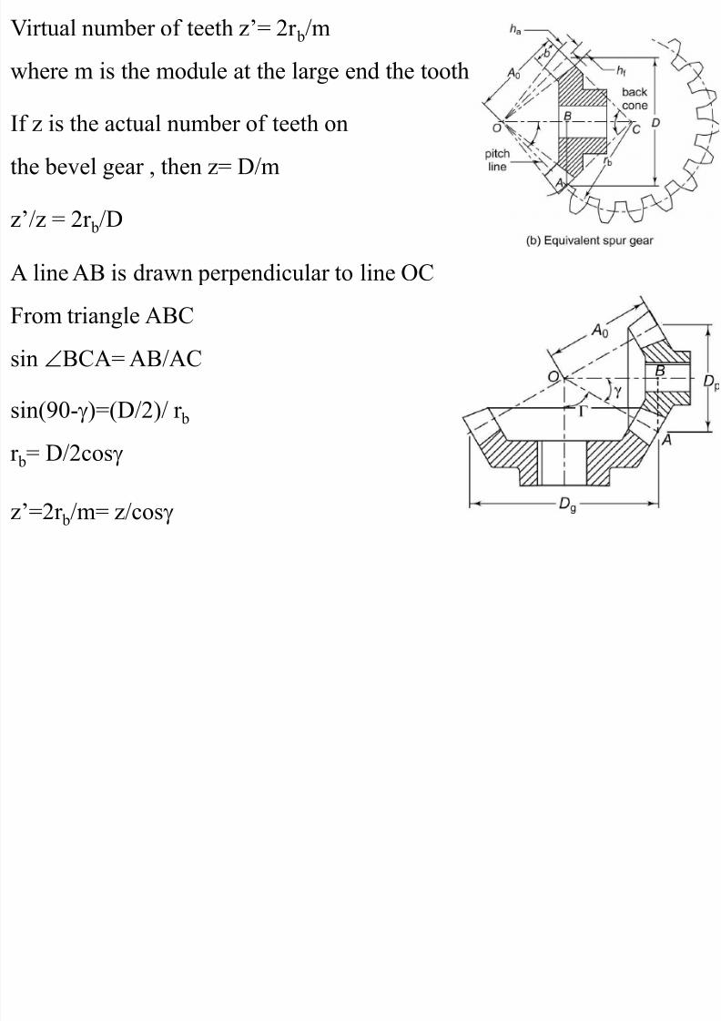
z’=2r b/m= z/cos
Virtual number of teeth z’= 2r b/m
where m is the module at the large end the tooth
If z is the actual number of teeth onthe bevel gear , then z= D/m
z’/z = 2r b/D
A line AB is drawn perpendicular to line OC
From triangle ABC
sin BCA= AB/AC
sin(90- )=(D/2)/ r b
r b= D/2cos
8/12/2019 Lecture 9 10th March
http://slidepdf.com/reader/full/lecture-9-10th-march 8/14
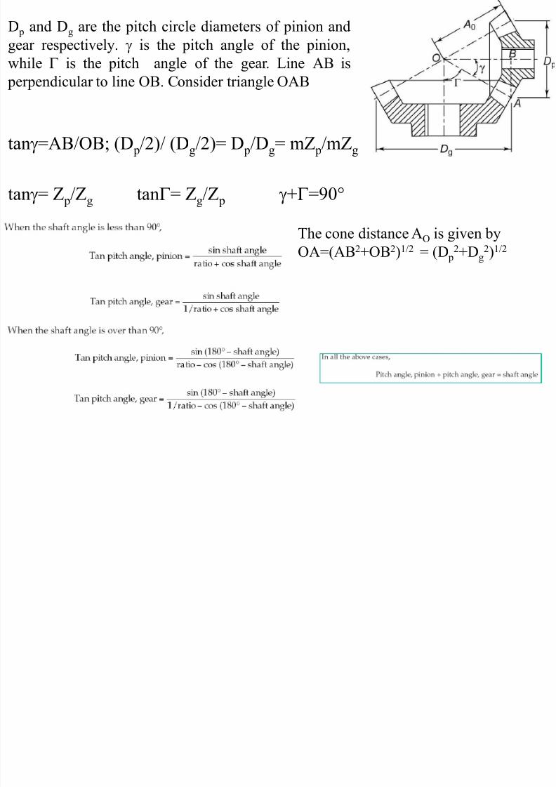
D p and D g are the pitch circle diameters of pinion andgear respectively. is the pitch angle of the pinion,while is the pitch angle of the gear. Line AB is
perpendicular to line OB. Consider triangle OAB
tan =AB/OB; (D p/2)/ (D g/2)= D p/Dg= mZ p/mZ g
tan = Z p/Zg tan = Z g/Z p + =90
The cone distance A O is given byOA=(AB 2+OB 2)1/2 = (D p
2+D g2)1/2
8/12/2019 Lecture 9 10th March
http://slidepdf.com/reader/full/lecture-9-10th-march 9/14
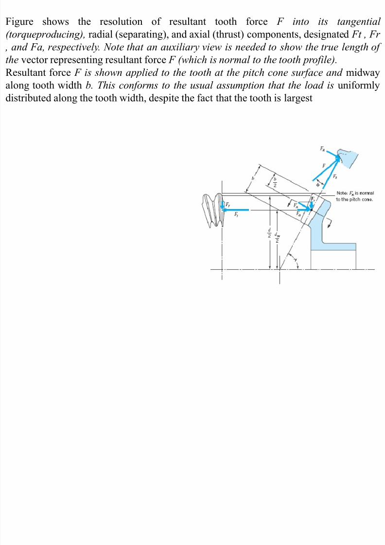
Figure shows the resolution of resultant tooth force F into its tangential(torqueproducing), radial (separating), and axial (thrust) components, designated Ft , Fr
, and Fa, respectively. Note that an auxiliary view is needed to show the true length ofthe vector representing resultant force F (which is normal to the tooth profile).Resultant force F is shown applied to the tooth at the pitch cone surface and midwayalong tooth width b. This conforms to the usual assumption that the load is uniformlydistributed along the tooth width, despite the fact that the tooth is largest

8/12/2019 Lecture 9 10th March
http://slidepdf.com/reader/full/lecture-9-10th-march 10/14
8/12/2019 Lecture 9 10th March
http://slidepdf.com/reader/full/lecture-9-10th-march 11/14
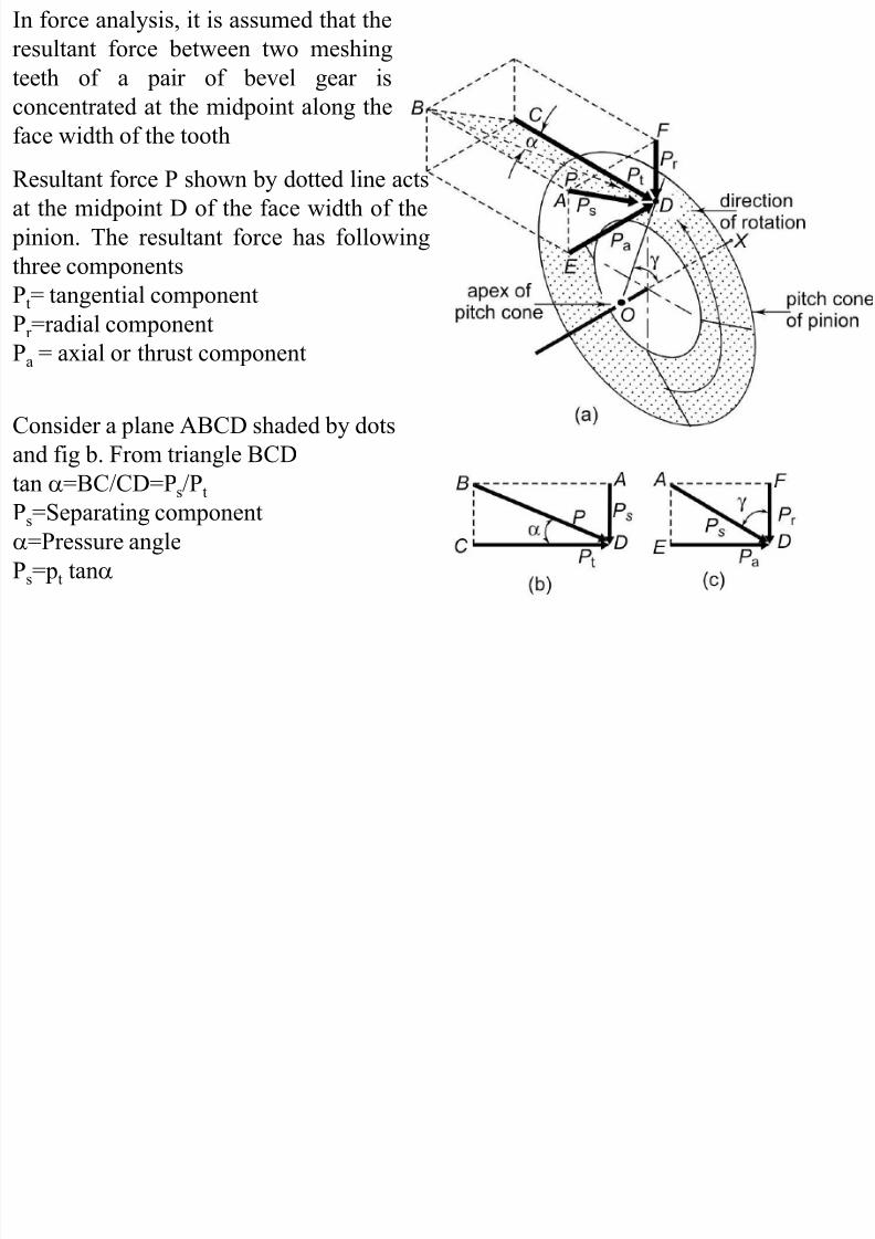
In force analysis, it is assumed that theresultant force between two meshingteeth of a pair of bevel gear isconcentrated at the midpoint along theface width of the tooth
Consider a plane ABCD shaded by dots
and fig b. From triangle BCDtan =BC/CD=P s/P tPs=Separating component
=Pressure anglePs=p t tan
Resultant force P shown by dotted line actsat the midpoint D of the face width of the
pinion. The resultant force has followingthree components
Pt= tangential componentPr =radial componentPa = axial or thrust component

8/12/2019 Lecture 9 10th March
http://slidepdf.com/reader/full/lecture-9-10th-march 12/14
The separating force P s is perpendicular to the pitch line OD, Therefore AD OD
Line FD is vertical ,while line OX is horizontal, Therefore, FD OX
There are two pairs of perpendicular lines and theirincluded angle should be equal. The angle betweenlines OD and OX should be equal to the angle
between the lines AD and FD. The angle betweenlines OD and OX is the pitch angle . Therefore theangle between lines AD and FD should be equal to the
pitch angle
Consider the plane DEAF, from triangle ADF
Pr =P scos
Pa=P ssin
The tangential component is determined from relation, P t= M t/r m
M t: Torque transmitted by gearsr m: radius of the pinion at midpoint along the face width
Since P s=P t tan
Pr = P t tan cos
Pa= P t tan sin

8/12/2019 Lecture 9 10th March
http://slidepdf.com/reader/full/lecture-9-10th-march 13/14
AC= D p/2
sin = AB/(b/2); AB=(b/2)sin
r m=[(D p/2)-(bsin /2)]
b : face width of the tooth
As seen in fig c, the radial component on the gear is equal to the axial
component on the pinion. Similarly the axial component on the gear is
equal to the radial component on the pinion
A two dimensional
representation of force
components is illustrated. In
figure b, the mean radius r m
where the resultant force acts
is given by
r m=AC-AB
8/12/2019 Lecture 9 10th March
http://slidepdf.com/reader/full/lecture-9-10th-march 14/14
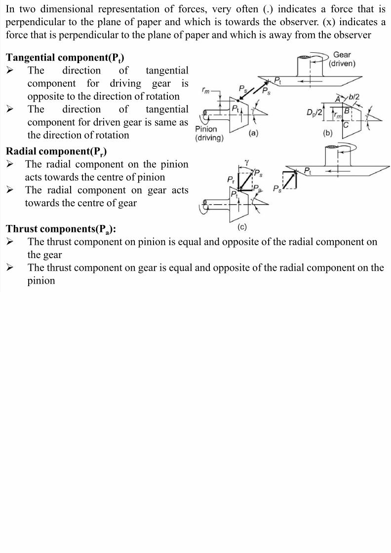
In two dimensional representation of forces, very often (.) indicates a force that is perpendicular to the plane of paper and which is towards the observer. (x) indicates aforce that is perpendicular to the plane of paper and which is away from the observer
Tangential component(P t)
The direction of tangentialcomponent for driving gear isopposite to the direction of rotationThe direction of tangentialcomponent for driven gear is same as
the direction of rotationRadial component(P r )
The radial component on the pinionacts towards the centre of pinionThe radial component on gear acts
towards the centre of gear
Thrust components(P a):The thrust component on pinion is equal and opposite of the radial component onthe gearThe thrust component on gear is equal and opposite of the radial component on the
pinion