lecture 8: serial communication - rowan university -...
TRANSCRIPT
1
Lecture 8: Serial Communication
Ying TangElectrical and Computer EngineeringRowan University
ECE342 Intro. to Embedded Systems
2
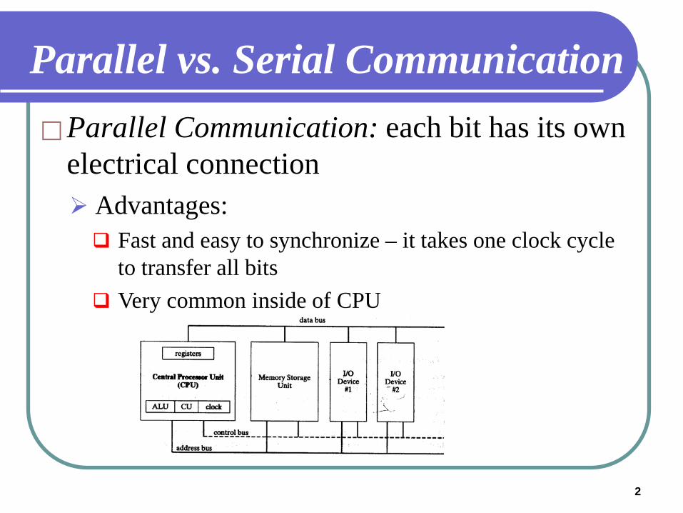
Parallel vs. Serial CommunicationParallel Communication: each bit has its own
electrical connection Advantages: Fast and easy to synchronize – it takes one clock cycle
to transfer all bits Very common inside of CPU
3
Parallel vs. Serial CommunicationParallel Communication: each bit has its own
electrical connection Disadvantages: Each bit has to have its own electrical connection Space is limited to have more parallel interconnects Longer connection has propagation latency issues
4
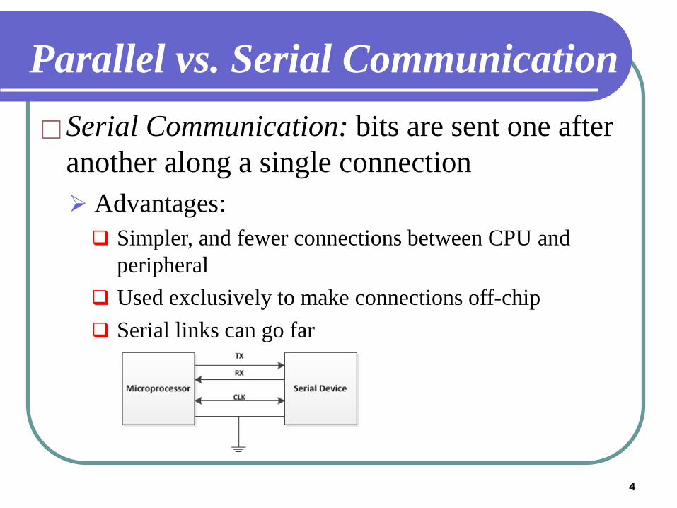
Parallel vs. Serial CommunicationSerial Communication: bits are sent one after
another along a single connection Advantages: Simpler, and fewer connections between CPU and
peripheral Used exclusively to make connections off-chip Serial links can go far
5
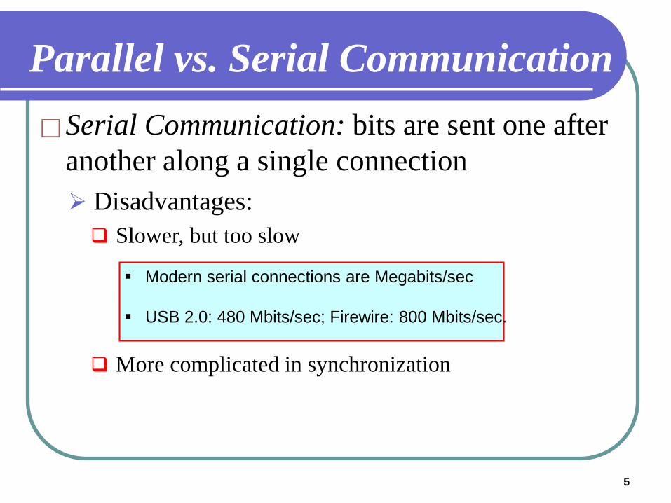
Parallel vs. Serial CommunicationSerial Communication: bits are sent one after
another along a single connection Disadvantages: Slower, but too slow
More complicated in synchronization
Modern serial connections are Megabits/sec
USB 2.0: 480 Mbits/sec; Firewire: 800 Mbits/sec.
6
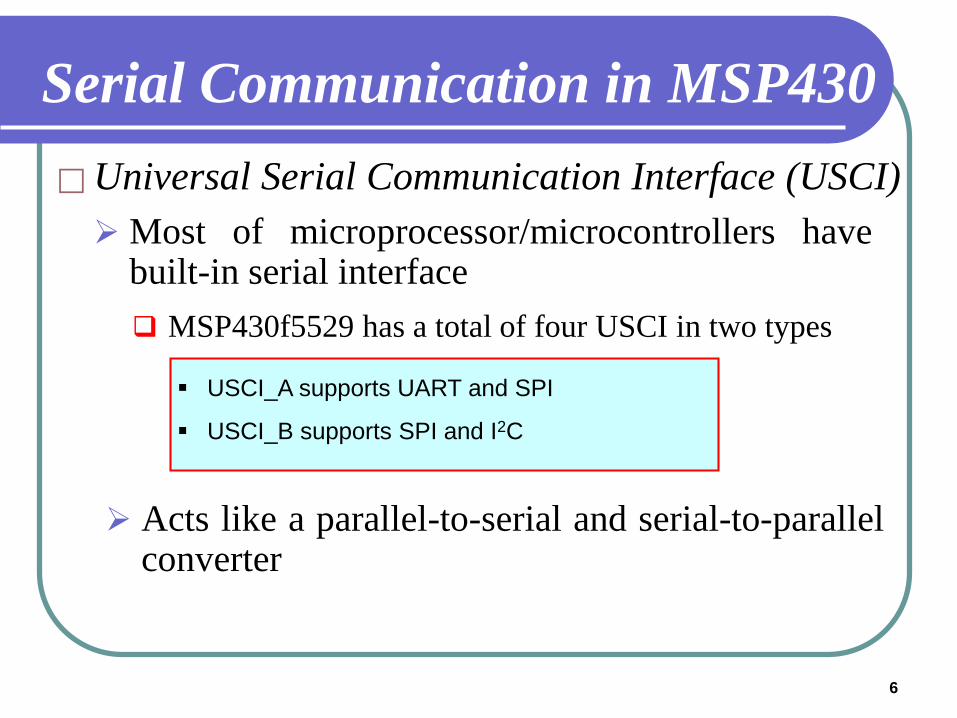
Serial Communication in MSP430 Universal Serial Communication Interface (USCI)Most of microprocessor/microcontrollers have
built-in serial interface MSP430f5529 has a total of four USCI in two types
USCI_A supports UART and SPI
USCI_B supports SPI and I2C
Acts like a parallel-to-serial and serial-to-parallelconverter
7
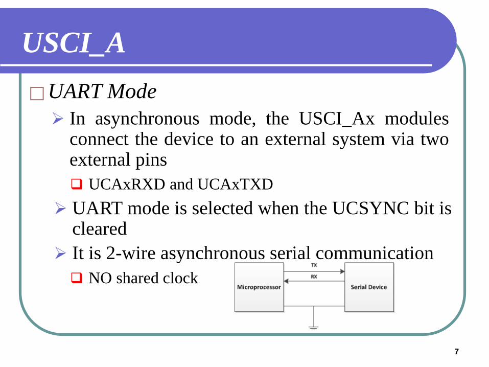
USCI_AUART Mode
UART mode is selected when the UCSYNC bit iscleared
In asynchronous mode, the USCI_Ax modulesconnect the device to an external system via twoexternal pins UCAxRXD and UCAxTXD
It is 2-wire asynchronous serial communication NO shared clock
8
9
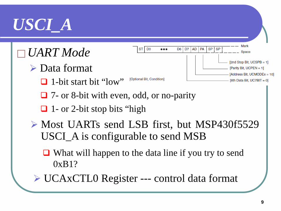
USCI_AUART Mode
Most UARTs send LSB first, but MSP430f5529USCI_A is configurable to send MSB
Data format 1-bit start bit “low” 7- or 8-bit with even, odd, or no-parity 1- or 2-bit stop bits “high
What will happen to the data line if you try to send 0xB1?
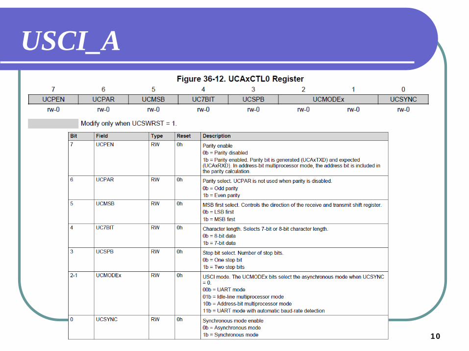
UCAxCTL0 Register --- control data format
10
USCI_A
11
USCI_A
12
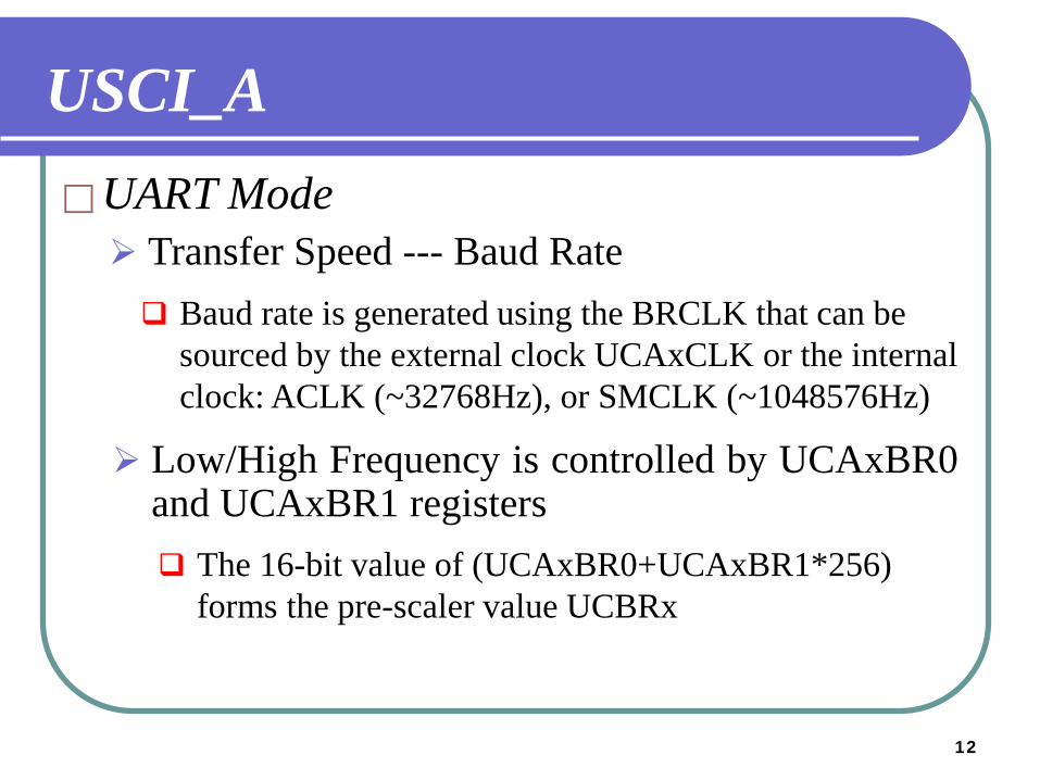
USCI_AUART Mode
Low/High Frequency is controlled by UCAxBR0and UCAxBR1 registers
Transfer Speed --- Baud Rate Baud rate is generated using the BRCLK that can be
sourced by the external clock UCAxCLK or the internal clock: ACLK (~32768Hz), or SMCLK (~1048576Hz)
The 16-bit value of (UCAxBR0+UCAxBR1*256) forms the pre-scaler value UCBRx
1313
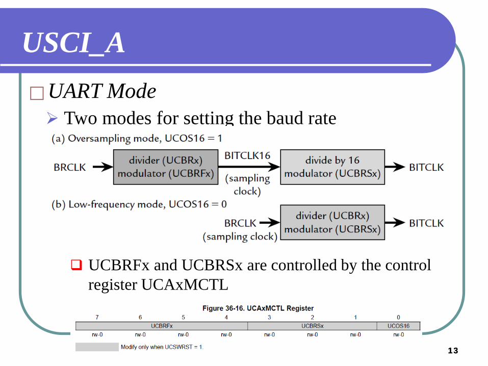
USCI_AUART Mode Two modes for setting the baud rate
UCBRFx and UCBRSx are controlled by the control register UCAxMCTL
14
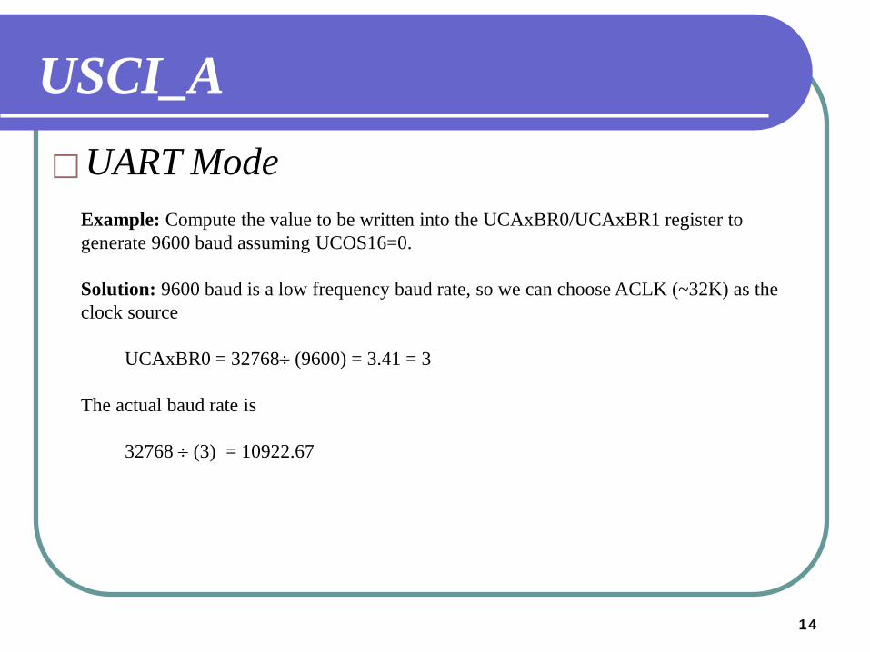
USCI_AUART Mode
Example: Compute the value to be written into the UCAxBR0/UCAxBR1 register to generate 9600 baud assuming UCOS16=0.
Solution: 9600 baud is a low frequency baud rate, so we can choose ACLK (~32K) as the clock source
UCAxBR0 = 32768÷ (9600) = 3.41 = 3
The actual baud rate is
32768 ÷ (3) = 10922.67
15
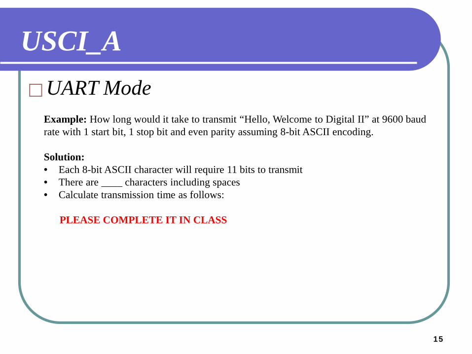
USCI_AUART Mode
Example: How long would it take to transmit “Hello, Welcome to Digital II” at 9600 baud rate with 1 start bit, 1 stop bit and even parity assuming 8-bit ASCII encoding.
Solution:• Each 8-bit ASCII character will require 11 bits to transmit• There are ____ characters including spaces• Calculate transmission time as follows:
PLEASE COMPLETE IT IN CLASS
16
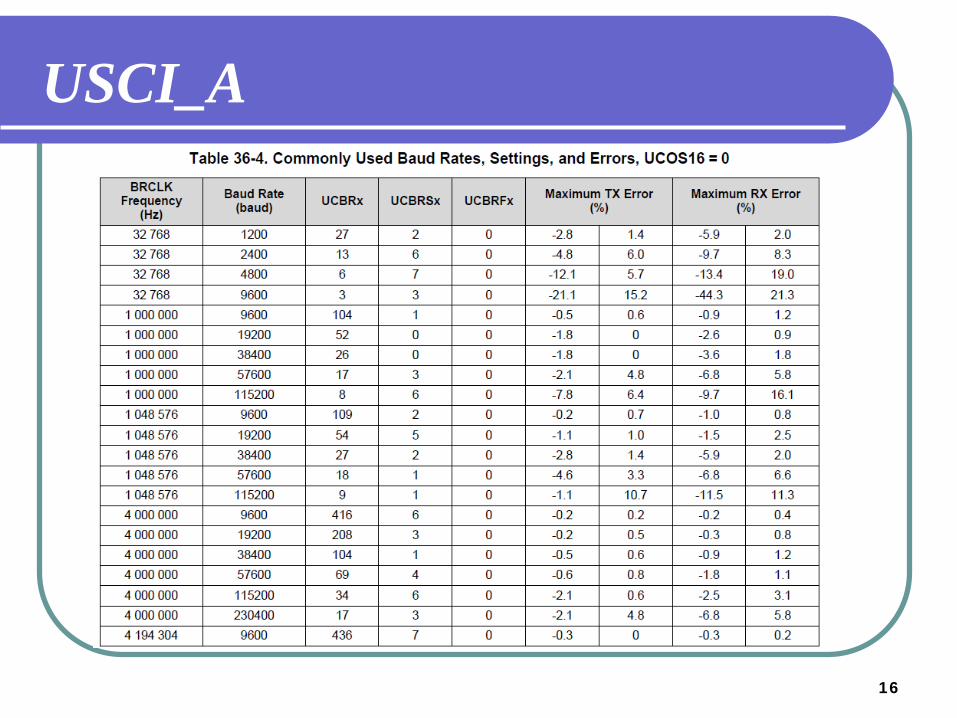
USCI_A
17
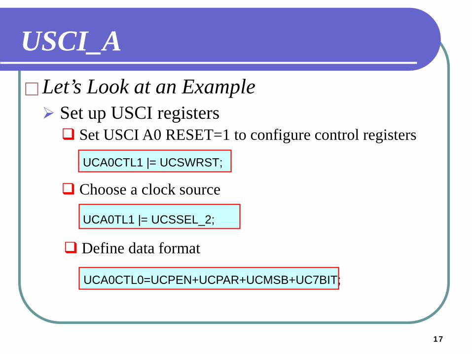
Let’s Look at an Example Set up USCI registers Set USCI A0 RESET=1 to configure control registers
UCA0CTL1 |= UCSWRST;
UCA0TL1 |= UCSSEL_2;
Choose a clock source
Define data format
UCA0CTL0=UCPEN+UCPAR+UCMSB+UC7BIT;
USCI_A
18
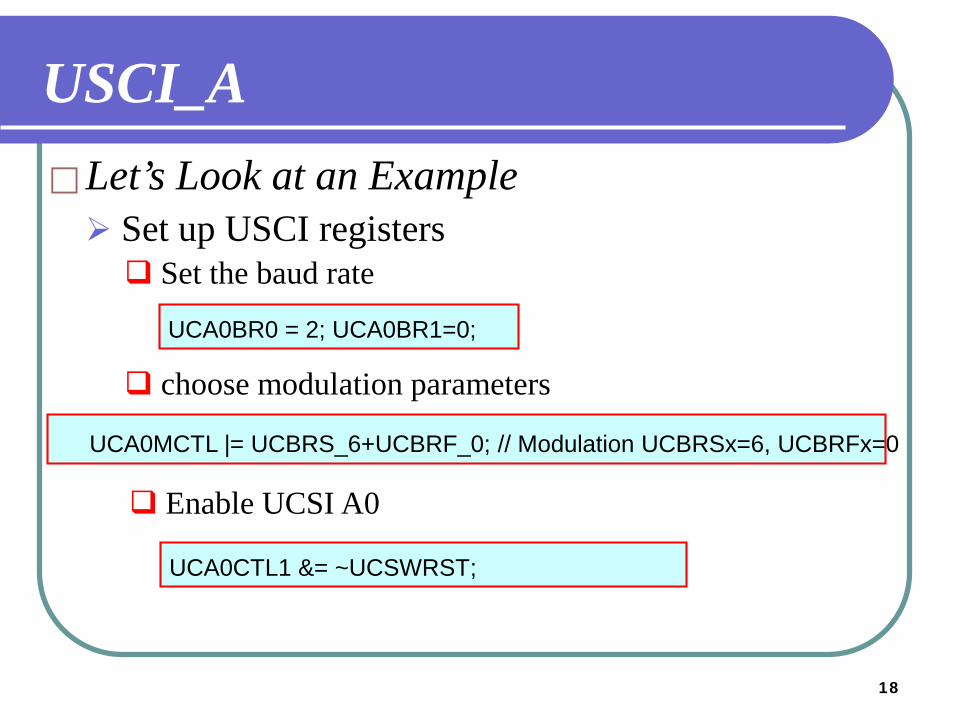
Let’s Look at an Example Set up USCI registers Set the baud rate
UCA0BR0 = 2; UCA0BR1=0;
UCA0MCTL |= UCBRS_6+UCBRF_0; // Modulation UCBRSx=6, UCBRFx=0
choose modulation parameters
Enable UCSI A0
UCA0CTL1 &= ~UCSWRST;
USCI_A
19
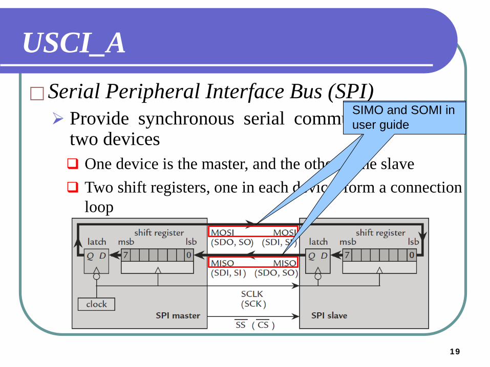
USCI_ASerial Peripheral Interface Bus (SPI) Provide synchronous serial communication btw
two devices One device is the master, and the other is the slave Two shift registers, one in each device, form a connection
loop
SIMO and SOMI in user guide
20
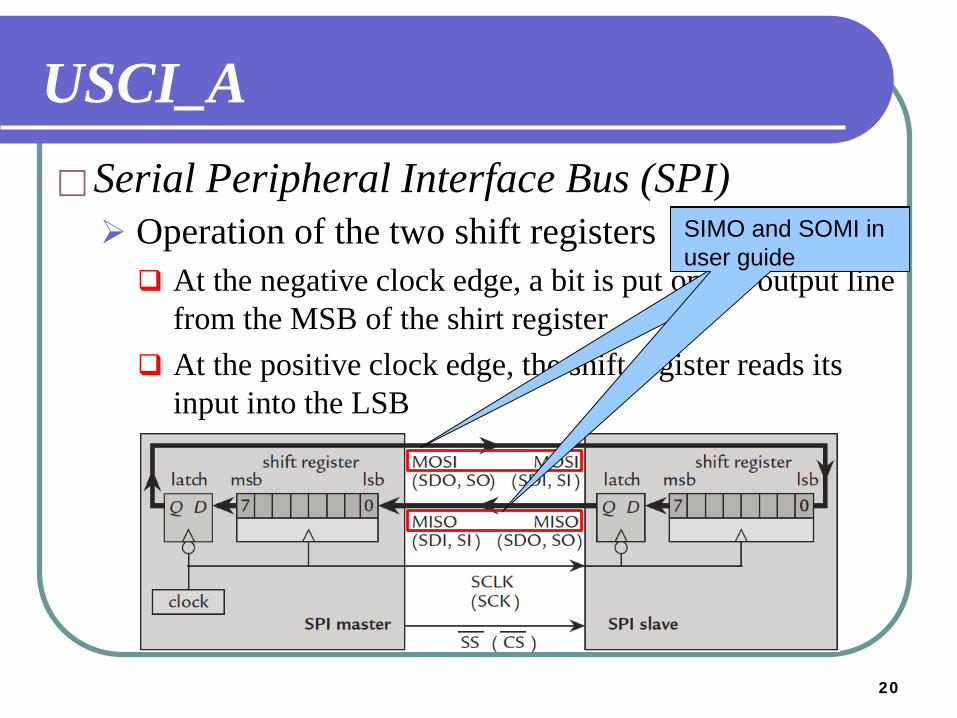
USCI_ASerial Peripheral Interface Bus (SPI) Operation of the two shift registers At the negative clock edge, a bit is put on the output line
from the MSB of the shirt register At the positive clock edge, the shift register reads its
input into the LSB
SIMO and SOMI in user guide
21
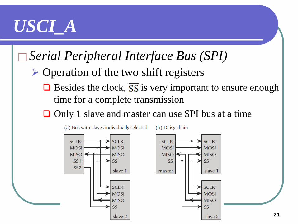
USCI_ASerial Peripheral Interface Bus (SPI) Operation of the two shift registers Besides the clock, is very important to ensure enough
time for a complete transmission Only 1 slave and master can use SPI bus at a time
22
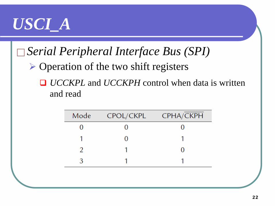
USCI_ASerial Peripheral Interface Bus (SPI) Operation of the two shift registers UCCKPL and UCCKPH control when data is written
and read
23
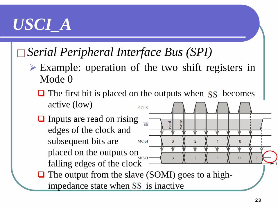
USCI_ASerial Peripheral Interface Bus (SPI) Example: operation of the two shift registers in
Mode 0 The first bit is placed on the outputs when becomes
active (low) Inputs are read on rising
edges of the clock and subsequent bits are placed on the outputs on falling edges of the clock
The output from the slave (SOMI) goes to a high-impedance state when is inactive
24
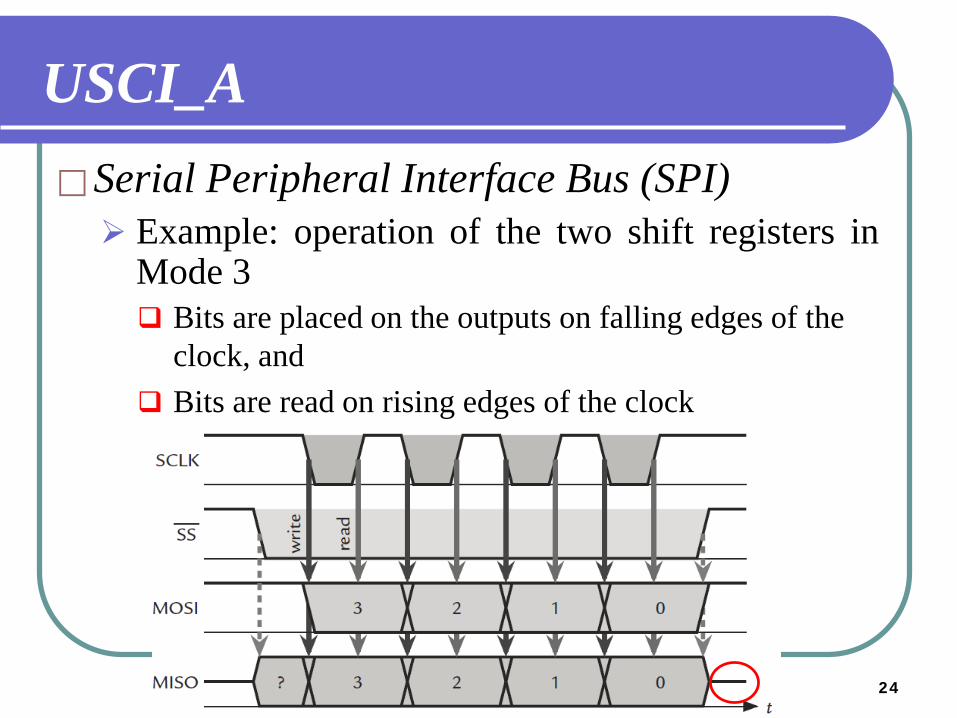
USCI_ASerial Peripheral Interface Bus (SPI) Example: operation of the two shift registers in
Mode 3 Bits are placed on the outputs on falling edges of the
clock, and Bits are read on rising edges of the clock
25
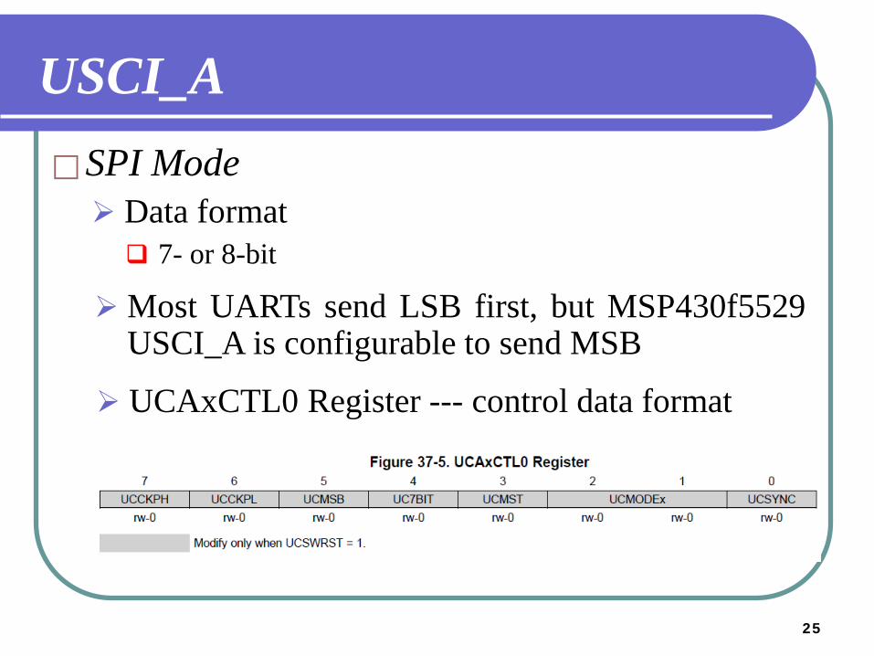
USCI_ASPI Mode
Most UARTs send LSB first, but MSP430f5529USCI_A is configurable to send MSB
Data format 7- or 8-bit
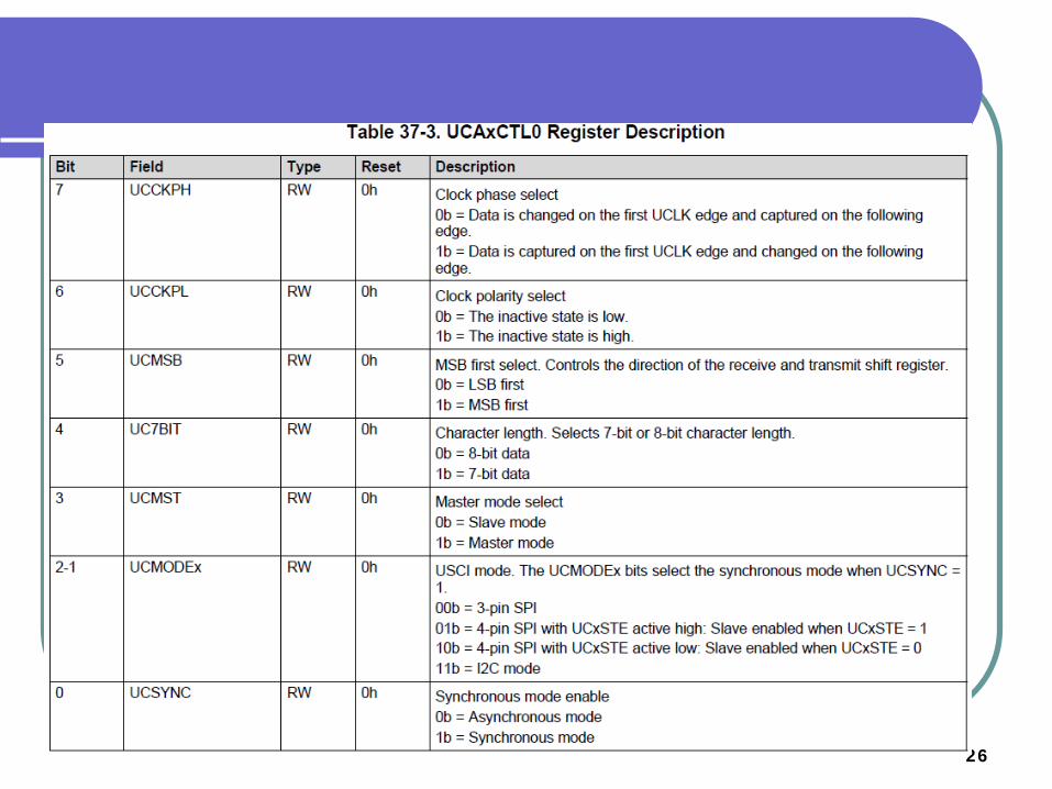
UCAxCTL0 Register --- control data format
26
2727
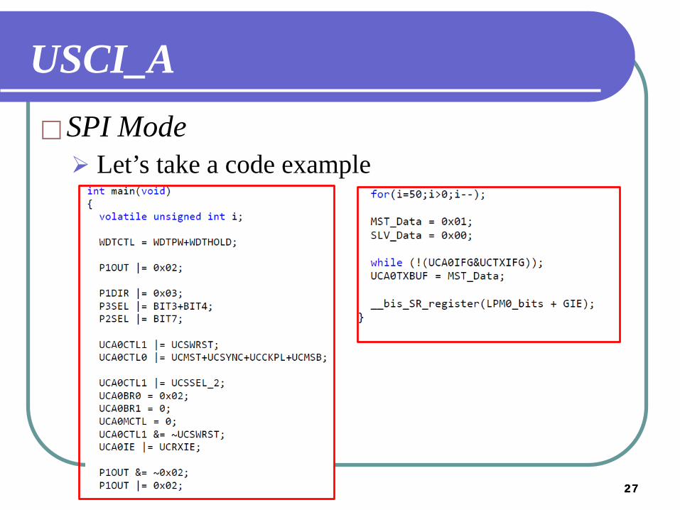
USCI_ASPI Mode Let’s take a code example
2828
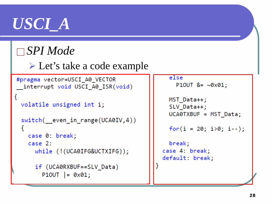
USCI_ASPI Mode Let’s take a code example