lecture 7 continuity, energy, and momentum equations (3)
TRANSCRIPT

1/36
Lecture 7
Continuity, Energy, and Momentum
Equations (3)

2/36Lecture 7 Continuity, Energy, and Momentum Equations
(3)
Contents
7.1 Linear Momentum Equation for Finite Control Volumes
7.2 The Moment of Momentum Equation for Finite Control Volumes
Objectives
- Derive the momentum equation by applying Newton’s 2nd law of motion
and Reynolds Transport Theorem
- Derive the moment of the momentum equation by applying Newton's 2nd
law to rotating fluid masses

3/36
7.1.1 Momentum Principle
The momentum equation can be derived from Newton's 2nd law of
motion
boundary (surface) forces: normal to boundary - pressure,
tangential to boundary - shear,
body forces - force due to gravitational or magnetic fields,
7.1 Linear Momentum Equation for Finite Control Volumes
(7.1) d mqdq dM
F ma mdt dt dt
M mqlinear momentum vector
F external force
pF
sF
bF
F
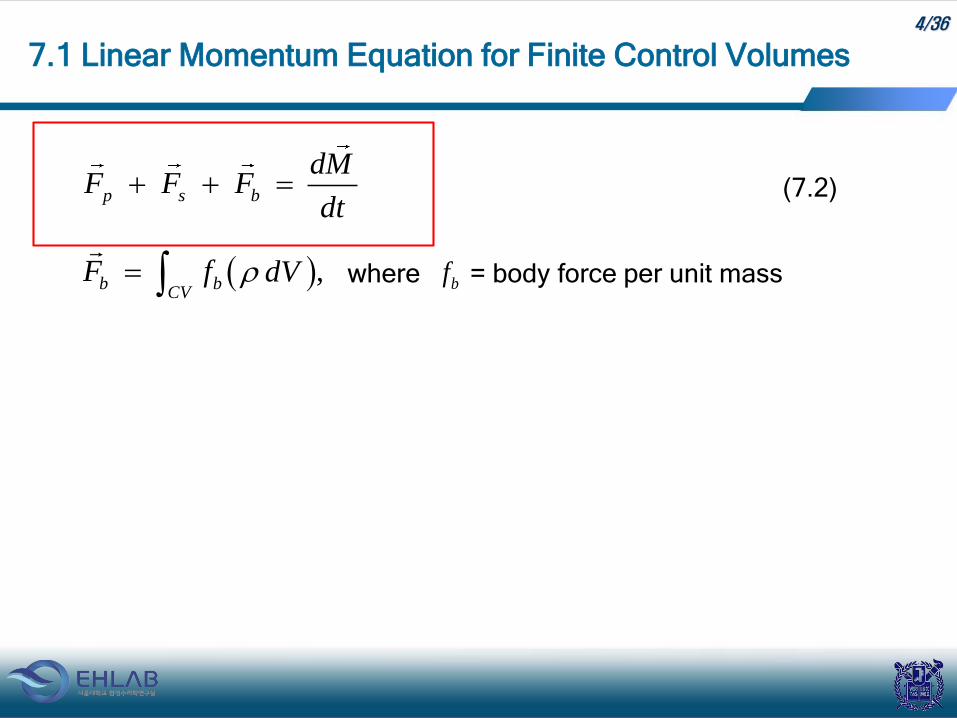
4/36
where = body force per unit mass
7.1 Linear Momentum Equation for Finite Control Volumes
p s b
dMF F F
dt
,b bCV
F f dV bf
(7.2)

5/36
7.1.2 The general linear momentum equation
Consider change of momentum
= total rate of change of momentum
= net momentum flux across the CV boundaries
+ time rate of increase of momentum within CV
where = momentum flux =
= vector unit area pointing outward over the control surface
7.1 Linear Momentum Equation for Finite Control Volumes
dM
dt
CS CV
q q dVq dAt
(7.3)
q q dA velocity mass per time
dA
Reynolds Transport Theorem

6/36
7.1 Linear Momentum Equation for Finite Control Volumes

7/36
7.1 Linear Momentum Equation for Finite Control Volumes
Substitute (7.3) into (7.2)
p s bCS CV
F F F q q dVq dAt
(7.4)
For steady flow and negligible body forces
p sCS
F F q q dA (7.5)
Eq. (7.4)
• It is applicable to both ideal fluid systems and viscous fluid systems
involving friction and energy dissipation.
• It is applicable to both compressible fluid and incompressible fluid.

8/36
7.1 Linear Momentum Equation for Finite Control Volumes
• Combined effects of friction, energy loss, and heat transfer appear
implicitly in the magnitude of the external forces, with corresponding
effects on the local flow velocities.
• Knowledge of the internal conditions is not necessary.
• We can consider only external conditions.
9/36
7.1 Linear Momentum Equation for Finite Control Volumes
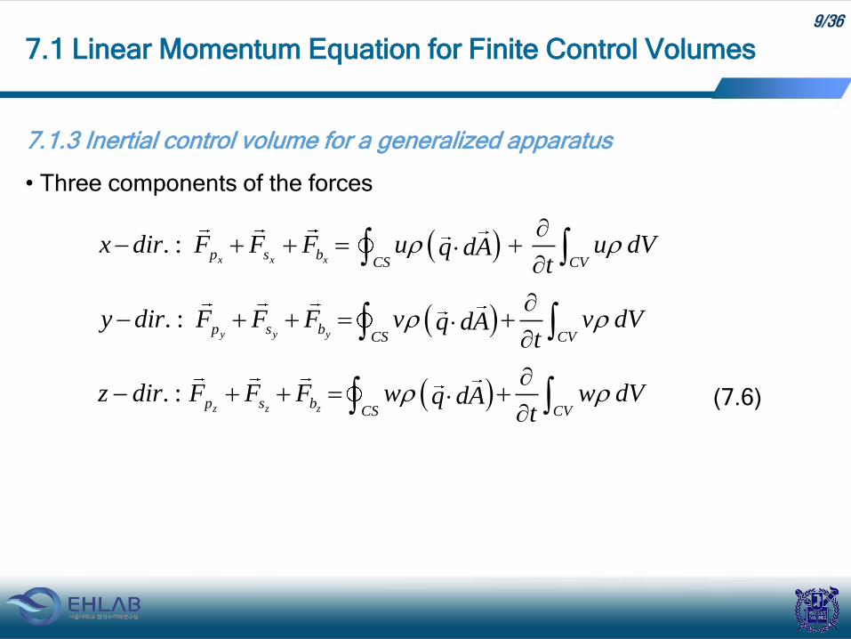
7.1.3 Inertial control volume for a generalized apparatus
• Three components of the forces
. :x x xp s b
CS CVx dir F F F u u dVq dA
t
. :y y yp s b
CS CVy dir F F F v v dVq dA
t
. :z z zp s b
CS CVz dir F F F w w dVq dA
t
(7.6)

10/36
7.1 Linear Momentum Equation for Finite Control Volumes
For flow through generalized apparatus
2 1. :
x x xp s bCV
x dir F F F u dQ u dQ u dVt
• For 1D steady flow,
0CV
q dVt

11/36
7.1 Linear Momentum Equation for Finite Control Volumes
• Velocity and density are constant normal to the flow direction.
2 1
.:x x xp s b x x xx dir F F F F V Q V Q
1 1 2 2Q Q Q
2 12 12 2 1 1 out inx xx xx x
V VV VV Q V Q Q Q
2 1
.: y yyV Q V Qy dir F
2 1
.: z z zz dir F V Q V Q
where V = average velocity in flow
direction

12/36
7.1 Linear Momentum Equation for Finite Control Volumes
If velocity varies over the cross section, then introduce momentum flux
coefficient
mq K V VAq dA
mq dQ K V Q
m
q dQK
V Q
• Non-uniform velocity profile

13/36
where
V = magnitude of average velocity over cross section = Q/A
= average velocity vector
Km = momentum flux coefficient ≥ 1
= 1.33 for laminar flow (pipe flow)
1.03-1.04 for turbulent flow (smooth pipe)
7.1 Linear Momentum Equation for Finite Control Volumes
V
2 1x m x m x
F K V Q K V Q
2 1m y m yy
K V Q K V QF
2 1z m z m z
F K V Q K V Q

14/36
7.1 Linear Momentum Equation for Finite Control Volumes
[Cf] Energy correction coefficient
2
2
2
2
e
q dQ
K
V Q

15/36
7.1 Linear Momentum Equation for Finite Control Volumes
A large tank mounted on rollers is
filled with water to a depth of 16 ft
above a discharge port. At time t =
0, the fast-acting valve on the
discharge nozzle is opened.
Determine depth h, discharge rate
Q, and force F necessary to keep
the tank stationary at t = 50 sec .
[Example 7-1] Continuity, energy, and linear momentum with unsteady flow
1
2
2
Assumptions:
0
const.
0
0 (datum)
atm
V
p p
h
16/36
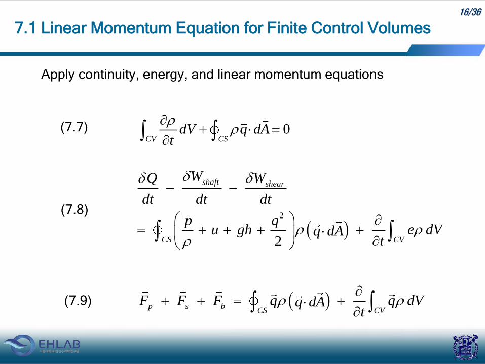
7.1 Linear Momentum Equation for Finite Control Volumes
Apply continuity, energy, and linear momentum equations
0CV CS
dV q dAt
(7.7)
2
2
shaft shear
CS CV
W WQ
dt dt dt
p qe dVu gh q dA
t
(7.8)
p s bCS CV
F F F q q dVq dAt
(7.9)

17/36
i) Use integral form of continuity equation, Eq. (7.7)
ii) Energy equation, Eq. (7.8)
~ no shaft work
~ heat transfer and temperature changes due to friction are negligible
7.1 Linear Momentum Equation for Finite Control Volumes
(because no inflow across the Section 1)
1 2n nCV
dV q dA q dAt
1 1, 0ndV A dh q dA
1 2 20
h
A dh V At
1 2 2
dhA V A
dt (A)

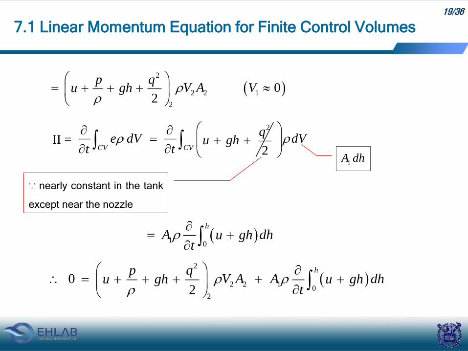
18/36
e = energy per unit mass =
7.1 Linear Momentum Equation for Finite Control Volumes
Q
dt
shaftW
dt
shear
W
dt
2
2CS CV
p qe dVu gh q dA
t
I II
2
2
qu gh
I = 2
2CS
p qu gh q dA
2 2
2 2 1 1
2 12 2
p q p qV A V Au gh u gh
19/36
7.1 Linear Momentum Equation for Finite Control Volumes
II =
2
2 2 1
2
02
p qV A Vu gh
1A dh
2
2CV
qe dV u gh
t t
CVdV
∵ nearly constant in the tank
except near the nozzle
10
h
A dhu ght
2
2 2 10
2
02
hp qV A A dhu gh u gh
t
20/36
7.1 Linear Momentum Equation for Finite Control Volumes
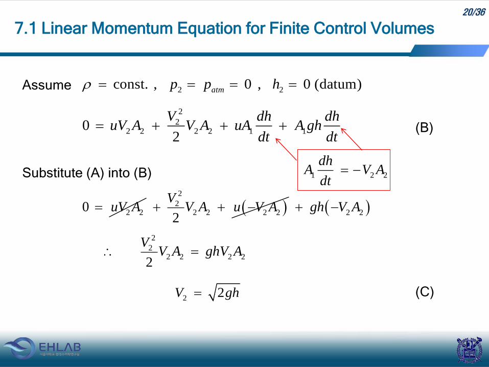
Assume 2 2const. , 0 , 0 (datum)
atmp p h
2
22 2 2 2 1 1
02
V dh dhuV A V A uA A gh
dt dt (B)
Substitute (A) into (B)
2 20 uV A
2
22 2 2 2
2
VV A u V A 2 2
gh V A
2
22 2 2 2
2
VV A ghV A
22V gh (C)
1 2 2
dhA V A
dt

21/36
7.1 Linear Momentum Equation for Finite Control Volumes
Substitute (C) into (A)
2 12
dhA gh A
dt
2
1
2dh A
gdtAh
Integrate
0 0 0
112 22
01
22
hh t h
h h h
dh Agdt h dh
hAh
21
220
1
2
2
gAh h t
A
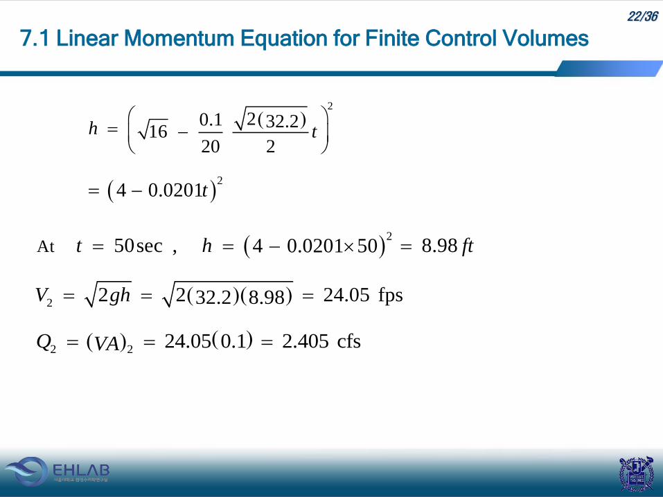
22/36
7.1 Linear Momentum Equation for Finite Control Volumes
2
20.1 32.216
20 2h t
2
4 0.0201t
2
At 50sec , 8.984 0.0201 50t h ft
2
2 2 24.05 fps32.2 8.98V gh
2 2
24.05 0.1 2.405 cfsQ VA

23/36
iii) Momentum equation, Eq. (7.4)
II = Time rate of change of momentum inside CV is negligible
if tank area is large compared to the nozzle area
7.1 Linear Momentum Equation for Finite Control Volumes
p sF F bF CS CV
q q dVq dAt
I II
1A 2 .A
2 1n n n nCS
q q q dA q q dAq dA 2 2 2V V A
2 2 2 2 2pxF V V A V Q
24.05 1.94 2.405 112 lbpx
F
I =

24/36
→ The vector sum of all the external
moments acting on a fluid mass
equals the time rate of change of the
moment of momentum (angular
momentum) vector of the fluid
mass.
Example: rotary lawn sprinklers, ceiling
fans, wind turbines
7.2 The Moment of Momentum Equation for Finite Control Volumes
r F
r M
7.2.1 The Moment of momentum principle for inertial reference systems
Apply Newton's 2nd law to rotating fluid masses
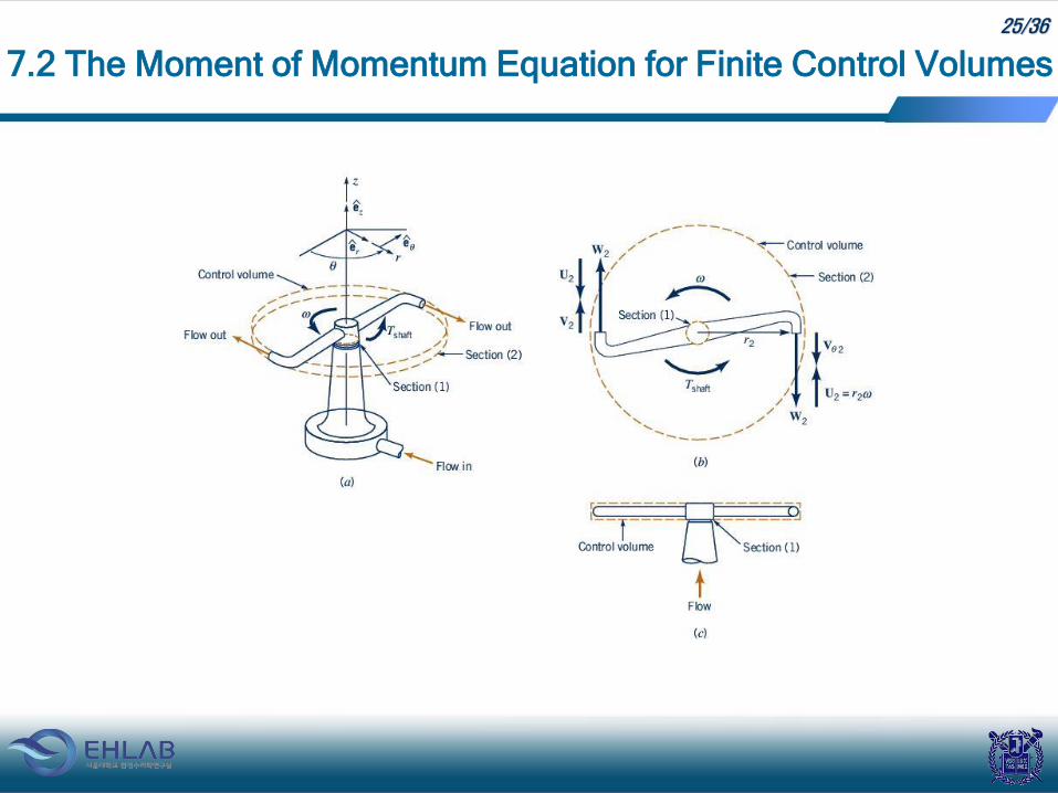
25/36
7.2 The Moment of Momentum Equation for Finite Control Volumes

26/36
where
= torque
= position vector of a mass in an arbitrary curvilinear motion
= linear momentum
7.2 The Moment of Momentum Equation for Finite Control Volumes
dT r F r M
dt (7.10)
r
M
T

27/36
[Re] Derivation of (7.10)
Take the vector cross product of
By the way,
7.2 The Moment of Momentum Equation for Finite Control Volumes
Eq. (7.1): dM
Fdt
r
dMr F r
dt
I
d dr dMr M M r
dt dt dt

28/36
where = angular momentum (moment of momentum)
7.2 The Moment of Momentum Equation for Finite Control Volumes
0dr dr
I M q m q qdt dt
sin0 0q q q q
ddMr Mr
dtdt
dr F r M
dt
r M

29/36
[Re] Torque
• translational motion →
Force – linear acceleration
• rotational motion →
Torque – angular acceleration
[Re] Vector Product
Magnitude = = area of parallelogram
direction = perpendicular to plane of and → right-handed triple
7.2 The Moment of Momentum Equation for Finite Control Volumes
T r F
V a b
sinaV b
a b
30/36
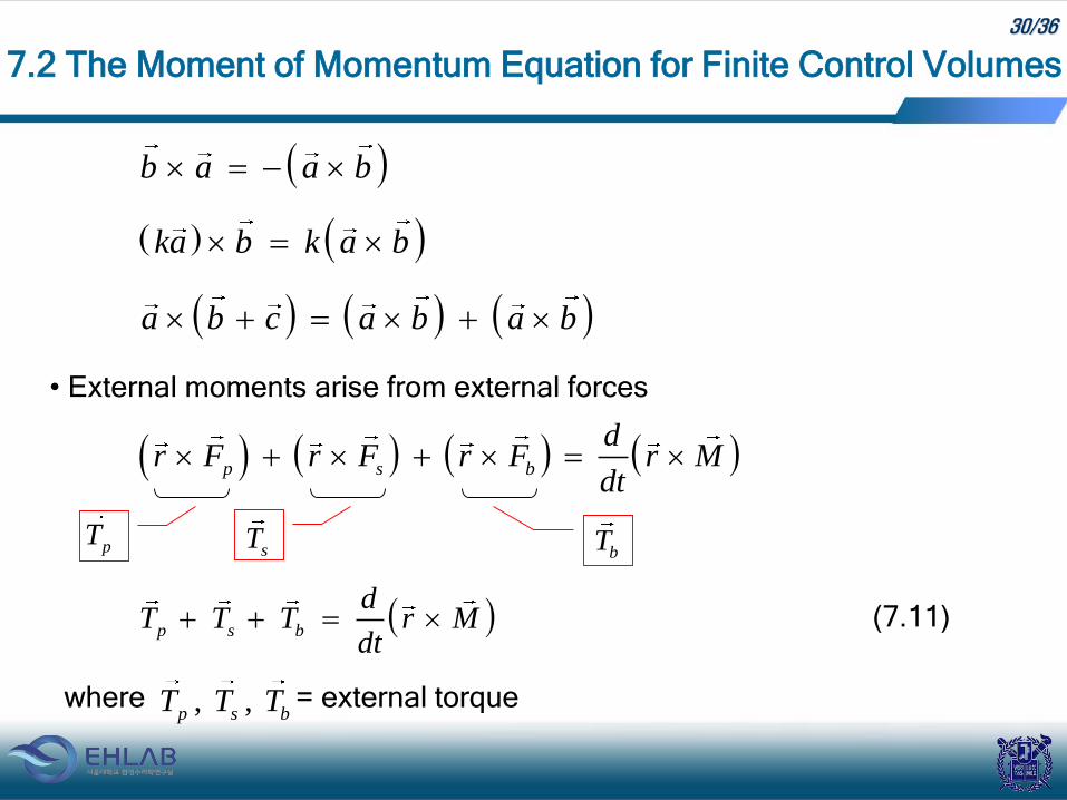
• External moments arise from external forces
where = external torque
7.2 The Moment of Momentum Equation for Finite Control Volumes
b a a b
ka b k a b
a b c a b a b
bTs
TpT
p s b
dr F r F r F r M
dt
p s b
dT T T r M
dt (7.11)
, ,p s b
T T T

31/36
7.2 The Moment of Momentum Equation for Finite Control Volumes
7.2.2 The general moment of momentum equation
(7.12)
CS CV
dMq q dVq dA
dt t
CS CV
dr M dVr q r qq dA
dt t
CS CV
T T T dVr q r qq dAp s b t
angle between andyz yz
q r
. : sin cos2
yz yzyz yzr qx dir r q rq
(7.3):

32/36
7.2 The Moment of Momentum Equation for Finite Control Volumes
. : cos cospy sy by zx zxCS CVy dir T T T dVrq rqq dA
t
. : cos cospz sz bz xy xyCS CVz dir T T T dVrq rqq dA
t
(7.13)
. : cos cospx sx bx yz yzCS CVx dir T T T dVrq rqq dA
t
fig_05_05

33/36
7-2. Derive the expression for the total force per unit width exerted by the
sluice gate on the fluid in terms of vertical distances shown in Fig. 4-20.
Homework Assignment # 3
Due: 1 week from today
7-1. Derive the equation for the volume rate of flow per unit width for the
sluice gate shown in Fig. 4-20 in terms of the geometric variable b, y1, and
CC. Assume the pressure in hydrostatic at y1 and ccb and the velocity is
constant over the depth at each of these sections.
Problems
xF

34/36
7-3. Consider the flow of an incompressible fluid through the Venturi
meter shown in Fig. 4-22. Assuming uniform flow at sections (1) and (2)
neglecting all losses, find the pressure difference between these sections
as a function of the flow rate Q, the diameters of the sections, and the
density of the fluid, . Note that for a given configuration, Q is a
function of only the pressure drop and fluid density.
Problems

35/36
7-4. Water flows into a tank from a supply line and out of the tank through
a horizontal pipe as shown in Fig. 4-23. The rates of inflow and outflow
are the same, and the water surface in the tank remains a distance h
above the discharge pipe centerline. All velocities in the tank are
negligible compared to those in the pipe. The head loss between the tank
and the pipe exit is HL (a) Find the discharge Q in terms of h, A,
and HL. (b) What is the horizontal force, FX required to keep the tank
from moving? (c) If the supply line has an area A’, what is the vertical
force exerted on the water in the tank by the vertical jet?
Problems
xF

36/36
7-5. Derive the one-dimensional continuity equation for the unsteady,
non-uniform flow of an incompressible liquid in a horizontal open channel
as shown in Fig. 4-29. The channel has a rectangular cross section of a
constant width, b. Both the depth, y0 and the mean velocity, V are
functions of x and t.
Problems