lecture 7 access to data & computer networks – physical level · pdf file10/30/2017...
TRANSCRIPT

10/30/2017 Vasile Dadarlat - Local Area Computer
Networks
1
Lecture 7
Access to Data & Computer Networks – Physical Level
Terminology
Serial Interface
Cable Modems
DSL technologies

10/30/2017 Vasile Dadarlat - Local Area Computer
Networks
2
ISP (Internet Service Provider)- An Internet service provider company that provides other companies or individuals with access to, or
presence on, the Internet
- Individual hosts and LANs are connected to an (ISP) through a point of presence (POP).
POP (Point of Presence)- An Internet access provider may operate several POPs distributed throughout its area of operation and
represents a collection of telecommunications equipment
CPE (Customer Premises Equipment)
- is the communications equipment located onsite with the host (example: modem)
Local loop” or “last mile
- the infrastructure between a provider’s installation and the site where the host is
Located
NAP (Network Access Point)
- a physical facility that provides the infrastructure to move data between connected networks; serve to tie
the ISPs together; ISP also connect using peering arrangements and
interconnections within geographic regions
CO (Central Office)
- the place where telephone companies terminate customer lines and locate switching equipment to
interconnect those lines with other networks

10/30/2017 Vasile Dadarlat - Local Area Computer
Networks
3
Common connections for SOHO (small office home office) LANs
Cable - offered by cable television service
providers, where data signal is carried on
television cable;
- high bandwidth, always on connection
DSL – on telephone lines (usually ADSL)
- high bandwidth, always on connection
Cellular - using cell phone network;
performance limited by phone and cell
tower the capabilities.
Satellite – using satellite dishes
- requires a clear line of sight to the satellite.
Dial-up Telephone - inexpensive option
using phone line and modems.
- low bandwidth not recommended for large
data transfer.
Cisco CCNA1

10/30/2017 Vasile Dadarlat - Local Area Computer
Networks
4
Serial Interface
Serial Transmission – all bits (of an octet) are transmitted (received) on a single line
Parallel Transmission – each bit (of an octet) uses a line
Data processing devices (or Data Terminal Equipment, DTE, like computers, terminals,
printers) do not (usually) include data transmission facilities, are stand alone equipment.
Need for an interface, called Data Circuit terminating Equipment (DCE, e.g. modem,
NIC –Network Interface Card)
First data transmissions used the telephonic system, a normal phone and a modem, so a
dial-up line (line established by circuit switching); takes time, unsafe =>
Use of leased lines, but are expensive!
Digital telephony – all signals and equipment are digital => big digital
telecommunication networks, with high speed and great reliability
Still remains (yet) analog the local loop, connecting the subscriber to Telecom office
All DTEs use for connecting to telephone line (either analog or digital) the serial
interface, so for the PCs the COM ports will be used.

10/30/2017 Vasile Dadarlat - Local Area Computer
Networks
5
For PCs the modem may be external or internal, today’s internal.

10/30/2017 Vasile Dadarlat - Local Area Computer
Networks
6
For your Laptop with interface adapter PCMCIA slot:

10/30/2017 Vasile Dadarlat - Local Area Computer
Networks
7
- In OSI terminology, communications interface act where data processing terminals
(computers, hosts, terminals, printers) connect to the transmission system, i.e. where is
the ‘end system to the network’ (data-circuit terminating equipment).
- Communications interface contains : DTE, DCE & interchange circuits.

10/30/2017 Vasile Dadarlat - Local Area Computer
Networks
8
Physical layer protocols describe this interface, in many aspects:
-electrical (voltages, currents, encoding techniques)
-electromechanical (connectors, pins location)
-functional (what circuits belongs to what pins & what signals on them
mean: data, control, timing, grounding)
-procedural aspects (sequence of events, ex.: protocol of using the standard
for answering calls…)
Physical aspects of connecting a DTE to a DCE – object of many standards:
EIA RS 232 (RS 232-D, from 1986, now RS 232-E, from 1991)
equivalent to ITU-T/CCITT V.24; V28 & ISO 2110
RS-449, followed by RS-530
Useful link for all kind of serial interfaces: www.arcelect.com

10/30/2017 Vasile Dadarlat - Local Area Computer
Networks
9
RS232 Serial Interface
Basics-initial variant 232C, followed by D & E variants, improving performances and
maintaining compatibility
-governs interface of DTE (computer) to DCE (modem)
-serial connection, up to 20kbaud over 15-16 m maximum (RS232C); further,
data speed improved to 50kbps (versions D & E)
-originally developed for dumb terminals to modems
-good noise immunity
-handshaking not used consistently
-very cheap, single asynchronous chip
-unbalanced interface for control & data (common reference ground)
-wiring isn’t set up to connect two DTEs together => use of null modem to cross
several wires
-initial asynchronous, now providing synchronous capabilities
Electrical SpecificationsLogic data representation by voltage transitions of min. 6V (both for data and
control)
off = 0 (+3 to +15V) on = 1 (-3 to –15V)

10/30/2017 Vasile Dadarlat - Local Area Computer
Networks
10
Mechanical Specifications-connector male/female with 25
pins, ‘D’ shape, one 12 pins row,
other with 13pins
-male connector on DTE, female
connector on DCE
-mechanical specifications
include: total connector’s width,
distance between successive
pins, between pins rows, etc.

10/30/2017 Vasile Dadarlat - Local Area Computer
Networks
11

10/30/2017 Vasile Dadarlat - Local Area Computer
Networks
12
Functional Specifications

10/30/2017 Vasile Dadarlat - Local Area Computer
Networks
13
Functional SpecificationsDefine which circuits connect to each of the 25 pins (see previous slide)
9 typically used pins:
20: Data Terminal Ready (DTE to DCE): tells that DTE is powered up and ready
6: Data Set Ready (DCE to DTE): tells DTE that DCE is powered up and ready
8: Carrier Detect (DCE to DTE): tells DTE that it detects a carrier on the line
4: Request to Send (DTE to DCE): tells DCE it wants to send data (usually for half
duplex)
5: Clear to Send (DCE to DTE): tells DTE that it can accept data, usually for half
duplex
2: Transmit (DTE to DCE): sends data to DCE for it to transmit
3: Receive (DCE to DTE): sends received data to DTE
1: Protective ground (for safety)
7: Signal Ground/Common Return (reference voltage for detecting signal levels)
Some PCs use 9 pins connectors; pin assignment is shown in the following table.

10/30/2017 Vasile Dadarlat - Local Area Computer
Networks
14
9
pin
Signal 25
pins
1 Carrier Detect 8
2 Received Data 3
3 Transmitted Data 2
4 Data Terminal Ready
20
5 Signal Ground 7
6 Data Set Ready 6
7 Request To Send 4
8 Clear To Send 5
9 Ring Indicator 22
Procedural Specifications
Gives the communication rules or how’s the
understanding between DTE – DCE, and between
pairs.
Sample example: an asynchronous private line
modem:
When turned-on and ready, modem (DCE) asserts Data
Set Ready
When DTE ready to send data, it asserts Request to Send
Also inhibits receive mode in half duplex
Modem responds when ready by asserting Clear to Send
DTE sends data
When data arrives, local modem asserts Receive Line
Signal Detector and delivers data

10/30/2017 Vasile Dadarlat - Local Area Computer
Networks
15
Dial Up Operation
10/30/2017 Vasile Dadarlat - Local Area Computer
Networks
16
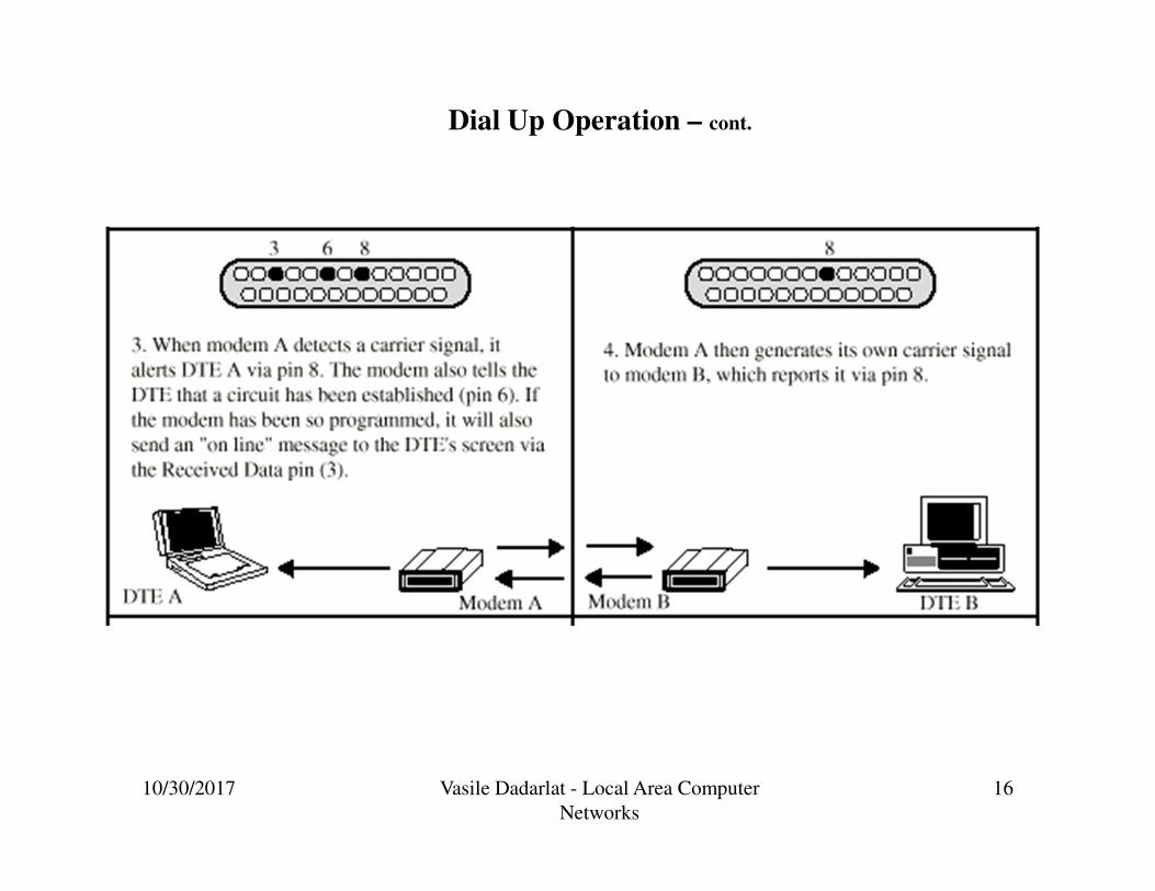
Dial Up Operation – cont.

10/30/2017 Vasile Dadarlat - Local Area Computer
Networks
17
Dial Up Operation –cont.

10/30/2017 Vasile Dadarlat - Local Area Computer
Networks
18
The wiring isn’t set up to connect two DTEs together => use of null modem to cross
several wires. Simplest case, the 3 wires short cable null modem, with the following
architecture:
Transmitted Data
Received Data
Request To Send
Clear To Send
Data Set Ready
Signal Ground
Data Carrier Detect
Data Terminal Ready
2
3
4
5
6
7
8
20
2
3
4
5
6
7
8
20

10/30/2017 Vasile Dadarlat - Local Area Computer
Networks
19
Other example of null modem,
with more wires, same effect!

10/30/2017 Vasile Dadarlat - Local Area Computer
Networks
20
For testing the serial interface (COM port), two simple tests:

10/30/2017 Vasile Dadarlat - Local Area Computer
Networks
21
RS 449 StandardDates from ’80s, improving the RS-232 standard, overcoming the defects.
Offers backward compatibility – very important, due to RS-232 huge usage => RS-
232 can be emulated by changing various connections.
Consists in fact of three standards:
Basic RS-449, giving mechanical, functional & procedural interfaces
Electric interface given by two standards:
RS-423A, similar with RS-232, using unbalanced transmission
(an unique return path for all signals)
RS-422A, assigns to each signal its own grounding (or, other, for
each signal is provided individual return path, isolated from other grounds); so
defines a balanced transmission.
Gives greater DTE control over DCE, but still not exist autodialing.
Mechanical connectors: 37 pins + an additional 9 pins, if secondary channel used.
Provides synchronous & asynchronous transmissions
Offers 10Mbps for a distance of max. 12m, and 100kbps for hundreds of meters,
when using RS-422A, and 3kbps @ 100m or 30kbps @ 10m length, for RS-423A.
Circuit description follows; remark that there are new circuits, like those used for
testing!
Future developments: RS-530, using balanced transmission, speed up to 2Mbps.

10/30/2017 Vasile Dadarlat - Local Area Computer
Networks
22
Mnemonics Circuit Description Mnemonics Circuit Description
SG Signal Ground SC Send Common
RC Receive Common IS Terminal in Service
IC Incoming Call TR Terminal Ready
DM Data Mode SD Send Data
RD Receive Data TT Terminal Timing
ST Send Timing RT Receive Timing
RS Request to Send CS Clear to Send
RR Receiver Ready SQ Signal Quality
NS New Signal SF Select Frequency
SR Signaling Rate Selector SI Signaling Rate Indicator
SSD Secondary Send Data SRD Secondary Receive Data
SRS Secondary Request toSend
SCS Secondary Clear to Send
SRR Secondary Receiver Ready LL Local Loopback
RL Remote Loopback TM Test Mode
SS Select Standby SB Standby Indicator

10/30/2017 Vasile Dadarlat - Local Area Computer
Networks
23
X21 Digital interfaceCCITT standard for direct digital connections to the digital telephone network.
Uses only 8 signal lines, on a 15 pin connector, allowing use of 2 channels (A, B)
Data rate fro 9600bps up to 64kbps
Use of more logic, instead of more signals (RS-449)
Allows bit and byte synchronization
X21bis standard allows analog signalling (is a subset of RS-232D), developed for
backward compatibility (use of analog telephone networks)
DCE provides a full-duplex, bit-serial, synchronous transmission path between
the DTE and the local PSE.
Trend continued with 8-pins physical connector for ISDN (Integrated Services
Digital Network)

10/30/2017 Vasile Dadarlat - Local Area Computer
Networks
24
Pin assignment
and functional
characteristics:

10/30/2017 Vasile Dadarlat - Local Area Computer
Networks
25
Signal Specification
Signal Ground (G): protective ground (earth).
DTE Common Return (Guard) – for the unbalanced mode, gives reference ground
for receivers in the DCE interface
Transmit (T) - carry data and control from the DTE to the DCE
Receive (R) - from DCE, indicates to the DTE the type of data
Indication (I) –controlled by DTE, indicates to the DCE the meaning of the data sent
on the transmit circuit
Byte Timing (B) - provides the DTE with 8-bit byte element timing
Signal Element Timing (S) - provides the DTE or DCE with timing information for
sampling the Receive line or Transmit line
Control line (C) – to DCE circuit, for extra control of DTE over DCE.

10/30/2017 Vasile Dadarlat - Local Area Computer
Networks
26
ISDN Physical Interface
Further evolution of X21 was the
specification of the ISDN physical
connection
Connection between terminal
equipment TE (c.f. DTE) and
network terminating equipment NE
(c.f. DCE)
ISO 8877
Cables terminate in matching
connectors with 8 contacts
Transmit/receive lines carry both data
and control

10/30/2017 Vasile Dadarlat - Local Area Computer
Networks
27
ISDN Electrical Specification
Balanced transmission
Signals carried on a channel made by two conductors, e.g. twisted pair
Signals (as currents) travel down one conductor and up the other (return way)
Differential signaling, as binary value depends on the voltage difference between
lines (value depends on direction of voltage); usual differences under 1V => low
power circuitry
Tolerates more noise and generates less then unbalanced transmissions, because
noise affects both lines, not their voltage difference
(Unbalanced, e.g. RS-232, uses single signal line and a (common) ground)
Data encoding depends on the data rate
Basic rate 192kbps uses pseudoternary
Primary rate uses alternative mark inversion (AMI) and B8ZS or HDB3

10/30/2017 Vasile Dadarlat - Local Area Computer
Networks
28
ModemStandard modem definition:The modemmodemmodemmodem is the interface between a DTE (like a PC) that generates digital signals, and the telephone system that carries analog signals.Modems encode digital signals onto analog signals by modulating an analog signal by changing the phase, frequency or amplitude of the signal, to represent 1s and 0s. The method of modulation defines the modem standard.The modem receives signals from the interchange circuits, respecting the serial interface standards.

10/30/2017 Vasile Dadarlat - Local Area Computer
Networks
29
For PCs the modem may be external or internal, today’s mostly internal.
Even if using an internal modem, these serial interface’s signals are generated by the
serial interface in the modem and are recognized by the terminal emulation software.

10/30/2017 Vasile Dadarlat - Local Area Computer
Networks
30
For your Laptop with interface adapter PCMCIA slot the modem appears like:
A PCMCIA modem being inserted into a
laptop computer. Attached to the card is an
adaptor which connects the card to a
standard RJ-11 telephone line

10/30/2017 Vasile Dadarlat - Local Area Computer
Networks
31
Modem standards issued by:
-Bell standards (old standards), ITU-T (former CCITT) recommendations, concerning
modulation and coding techniques
-EIA/TIA, ITU-T for interfaces
Categories of modems: (see table on next slide)
-operating speed –low, medium & high speed
-implemented standard
-type of transmission (asynchronous, synchronous)
-type of modulation (FSK, PSK, QAM)
-type of telephonic lines (dial-up or leased)
-complexity (traditional or smart)
-other modems (ISDN modems, coax cable modems, LAN modems, wireless and
cellular modems)

10/30/2017 Vasile Dadarlat - Local Area Computer
Networks
32
Data
rate
Standard Body Line Type Modulation
Technique
Transmission
Type
Duplex
Full/Half
300 Bell 103, CCITT V21 Dial-up FSK Asynchronous Half+Full
600 CCITT V22 Dial-up/leased PSK Asynchronous Half+Full
1200 Bell 202, CCITT V22 Dial-up/leased PSK Asynch/Synch Half+Full
2400 CCITT V22bis Leased QAM Asynchronous Half+Full
4800 CCITT V27 Leased PSK Synchronous Half+Full
9600 Bell 209, CCITT V32 Dial-up/leased QAM Asynch/Synch Half+Full
14400 CCITT V32bis Dial-up/leased QAM Asynch/Synch Half+Full
33600 CCITT V34 Dial-up/leased PSK Asynch/Synch Full
56600 CCITT V90 Dial-up/leased QAM Asynchronous Full
10/30/2017 Vasile Dadarlat - Local Area Computer
Networks
33
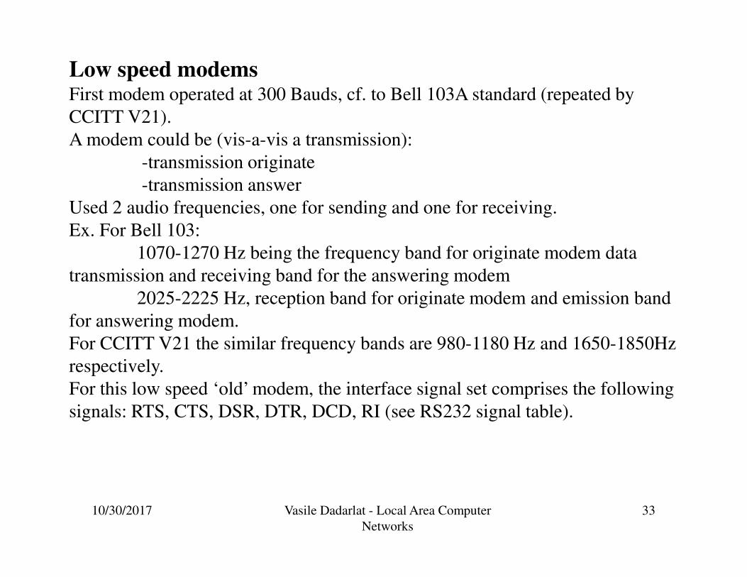
Low speed modemsFirst modem operated at 300 Bauds, cf. to Bell 103A standard (repeated by
CCITT V21).
A modem could be (vis-a-vis a transmission):
-transmission originate
-transmission answer
Used 2 audio frequencies, one for sending and one for receiving.
Ex. For Bell 103:
1070-1270 Hz being the frequency band for originate modem data
transmission and receiving band for the answering modem
2025-2225 Hz, reception band for originate modem and emission band
for answering modem.
For CCITT V21 the similar frequency bands are 980-1180 Hz and 1650-1850Hz
respectively.
For this low speed ‘old’ modem, the interface signal set comprises the following
signals: RTS, CTS, DSR, DTR, DCD, RI (see RS232 signal table).

10/30/2017 Vasile Dadarlat - Local Area Computer
Networks
34

10/30/2017 Vasile Dadarlat - Local Area Computer
Networks
35
Modem Commands (Hayes-compatible modem)
These are commands (character strings) that the terminal emulator can send to the
modem to instruct it to perform operations, such as automatic dial. Interface signal set
comprises only the lines Tx (Transmit), Rx (Receive), and ground.
The modem is in one of the states:
-receive command from DTE
-on-line
-hang-up, or carrier-wait.
General format of the command:
AT command
Where command is a letter, followed (eventually) by a parameter.
The following are examples of a few of the AT (attention) commands:
ATDT n: Dial phone number <n>, using touch tone
ATDP n: Dial using pulse
ATH: Hangup
ATH1: Pick up the phone line
Smartmodems (Hayes compatible)Cf. RS232-C data and control lines are separated. Smartmodems ‘understand’
commands and status information using characters, so no more signal separation..

10/30/2017 Vasile Dadarlat - Local Area Computer
Networks
36
Introduction to:
ISDN ModemISDN (Integrated Services Digital Network), offers services on a full digital network.
ISDN modems, known as TA (Terminal Adapters).
An ISDN line is split in channels (see table):
B (Bearer) channel – carries (PCM coded digital) voice + data up to 64kbps
D (data signaling) channel – carries control for B channels; speed 16kbps or
64kbps
Usually B and D channels use separate paths, speeding up the transmissions
H (High speed) channel – data transport at speeds of Mbps
ITU-T defines two types of services:
Channel Bit Rate Interface
B 64kbps Basic access
H0 384kbps Primary rate access
H11 1536kbps Primary rate access
H12 1920kbps Primary rate access
D16 16kbps Basic access
D64 64kbps Primary rate access
BRI (Basic Rate Interface),
operating at 192kbps, contains
2 B channels and one D
channel at 16kbps (2B + D16)
PRI (Primary Rate Interface),
signalling at 64kbps and
operating at 1.544Mbps in US
(23B + D64), or 2.048Mbps in
Europe (30B + D64)

10/30/2017 Vasile Dadarlat - Local Area Computer
Networks
37
Use of H channels instead of B (see table for more details):
Interface Bit Rate Interface
Structure
Basic access
Primary rate
access
192 kbps
1544 kbps
2048 kbps
2B+D16
23B+D64
3H0+D64
30B+D64
5H0+D64
H12+D64
TA has similar functions as a normal modem, plus those for adapting the variable data
rate of the DTE to the constant B channel data rate. Also transforms analog voice or fax
data into digital. The commands for a TA have similar structure as for the smart Hayes
modem (AT … commands).

10/30/2017 Vasile Dadarlat - Local Area Computer
Networks
38
A little bit more about the physical level of ISDN:
ISDN: First important change from analog to digital telephony, from circuit
switching telephony to packet switching based
Digital data exchanged between subscriber (user) and network terminal equipment
(NTE) is Full Duplex => Separate physical line for each direction
Pseudoternary coding scheme: 1=no voltage, 0=positive or negative 750mV +/-10%
Basic rate: data rate of 192kbps, i.e. one 48 bit-long frame every 250 µs; Basic
access uses synchronous TDM two 64kbps B channels and one 16kbps D channel
(2B+D16) => This gives 144kbps multiplexed over 192kbps => Remaining capacity
used for framing and synchronization.
Use of LAP-D frames (see the following data link protocol HDLC)
Two kind of frames: from/to subscriber to/from Terminal Equipment. Structure:
From 48 bit: 16bit for each of B channels and 4 bit for D channel.
F –framing bit (positive pulse, followed by a negative one L, for dc balance
FA – auxiliary framing; E: D-echo channel bit (retransmission by NTE of the most
received D bit; A: activation bit for NTE (allows low power-consumption mode)

10/30/2017 Vasile Dadarlat - Local Area Computer
Networks
39
ISDN LAP-D Frame Structure (basic access)

10/30/2017 Vasile Dadarlat - Local Area Computer
Networks
40
Primary ISDN Interface: synchronous TDM of multiple channels, allows point-to-
point configurations; 2 data rates defined:
DS-1 of 1.544Mbps, based on T1 trame: 24*8data bit + 1 framing, every 125 µs; 8000
frames/sec => each channel supports 64kbps; implements 23B+D64; data encoding
using AMI (alternate mark inversion) – B8ZS(bipolar-8 zeros substitution)
E1 trame, at 2.048Mbps for 30B+D64; one 256 bit frame every 125µs, 8000 frames/sec
each channel supports 64kbps; first time slot for framing and synchronization; data coded
sing AMI – HDB3(high density bipolar 3zeros)
Primary ISDN Frame Formats

10/30/2017 Vasile Dadarlat - Local Area Computer
Networks
41
B-ISDN (Broadband ISDN)
N-ISDN (Narrow – ISDN) deal with 64kbps channels (type B); with H type
channels (actual H channel offers tens of Mbps) => development of B-ISDN,
offering a transport of packets (cells) at a rate beginning with 155Mbps.
Transfer mode implementing B-ISDN (dealing with transmission and switching
aspects) is the ATM (Asynchronous Transfer Mode).
The ATM transport unit is the cell, small packet of 53bytes, 5 octets for control and
48 bytes payload.
The protocol hierarchy of ATM is depicted below:
At the Physical level, the ATM technology
is based on SONET and SDH standards.

10/30/2017 Vasile Dadarlat - Local Area Computer
Networks
42
Cable ModemsDevices allowing high-speed access to the Internet via a cable television network. Even
similar with voice-band modems, more than 500 times faster. Voiceband modems
operate up to 56kbps, cable modems deliver 30-40Mbps of data on a 6MHz TV channel
In a cable network:
-data from the network to the user: downstream
-data from the user to the network: upstreamDownstream and upstream
bandwidths may be configured
after application (domestic user-
low upstream bandwidth,
business office may require a
higher upstream band)
Simple layout:
-one-to-two splitter for
transmitting TV services to set
top box, and for transmitting data
through cable modem to the
computer

10/30/2017 Vasile Dadarlat - Local Area Computer
Networks
43
The front of a cable modem
showing its various indicators.
The back of a cable modem with
standard coaxial television cable
connector, telephone jacks and
Ethernet jacks - connects the
modem to a computer.
At the other end of the cable there is the head-end, may be a CATV provider or an ISP
(Internet Service Provider), let’s say a head-end point-of-presence, allowing, by use of
a multiplexed network interface, the access to the Internet.
• User-to-network data (upstream): 5–40 MHz
• Television delivery (downstream): 50–550 MHz
• Network to user data (downstream): 550–750 MHz

10/30/2017 Vasile Dadarlat - Local Area Computer
Networks
44
Other application with the
downstream offered by CATV
and upstream by cable
modems.
Other application, with the
use of the QPSK Signal
from a Cable Modem and use
of a transverter, for full
wireless communications
using CATC antennas.

10/30/2017 Vasile Dadarlat - Local Area Computer
Networks
45
Wireless modemsMany kinds of wireless modems:
-RF modem for a wireless network (use of ISM bands)
-cellular modem for cellular communications, attached to the phone
Example: use the ISM Band for Wireless Return 900 MHz/2.4 GHz:

10/30/2017 Vasile Dadarlat - Local Area Computer
Networks
46
DSL (Digital Subscriber Line)
Link between subscriber and network (local loop); tens of millions installed;
Reinstall?
⇒need for exploiting the existing base of TP wired structure; initially designed for
voice-grade analog transmissions with 4kHz bandwidth, TP may carry data using
signals over a spectrum of more than 1MHz => use of modems for digital high rate
data transmissions, using currently installed twisted pair cable.
- DSL refers to the analog local loop between each customer premises and its local
central office, and a DSL modem is required at each end of the loop

10/30/2017 Vasile Dadarlat - Local Area Computer
Networks
47
ADSL (Asymmetric Digital Subscriber Line)
ADSL initially designed for video-on-demand, now appropriate for high-speed
Internet access.
Asymmetric because, from the user point, there is greater capacity downstream
(from service provider to customer) than upstream.
ADSL uses FDM for managing the 1MHz bandwidth:
-Lowest 25kHz for voice (Plain Old Telephone Service): 0 to 4kHz for voice, rest
for guard, avoiding interference with other channels
-Use echo cancellation or FDM to give (to allocate) two bands: one for upstream ,
one for downstream
-Use FDM within each of two bands.
Supports loop length in the range of 5.5km.

10/30/2017 Vasile Dadarlat - Local Area Computer
Networks
48
Echo Cancellation
Signal processing technique,
allowing digital transmissions in
both directions on a single line
simultaneously. The transmitter
must subtract the echo of its own
transmission from the incoming
signal, to recover the signal sent
by the other side.
Advantages:
-more flexibility for upstream
bandwidth changes, simply
extending the area of overlap
-downstream bandwidth in the
good part of the spectrum (not so
many HFs) => a lower attenuation

10/30/2017 Vasile Dadarlat - Local Area Computer
Networks
49
DMT (Discrete Multitone)
DMT modem allows multiple carrier
signals at different frequencies;
-upstream and downstream
bandwidths are split in a number of
4kHz sub-channels, transmitting a
number of bits on each channel.
Initially modem send test signal on
each subchannel, and then use those
subchannels with better signal to noise
ratio.
If used 256 downstream subchannels at 4kHz, carring data at 60kbps, will result a data
rate of 15.36Mbps. Transmission impairments bring this down to 1.5Mbps to 9Mbps.
Use of QAM (Quadrature Amplitude Modulation) – analog signaling technique, a
combination of AM and PM. May assign different number of bits/transmitted signal.
Sample example: data string is split in two sub-strings. One sub-string modulates the
carrier, the other modulates the carrier shifted with 90º. The composed QAM signal is
the sum: s(t) = d1(t)cos 2πft + d2(t)sin 2πft. => signal has 4 states, for coding 2 bits.

10/30/2017 Vasile Dadarlat - Local Area Computer
Networks
50
xDSL – recent schemes for high-data speed transmissions on ADSL
High data rate DSL
Single line DSL
Very high data rate DSL

10/30/2017 Vasile Dadarlat - Local Area Computer
Networks
51
Alternative Broadband Access Technologies
Fiber-to-the-home (FTTH)
- common solution: using passive optical network (PON)
- a single transceiver in the CO serving multiple customers
- splitters and couplers to distribute the service among the different subscribers
Cable
- hybrid fiber-coax (HFC)
- fiber-optic cable carrying signals between the cable headend and fiber nodes in the
network, from which existing coaxial cable is used to cover the “last mile” to the
subscribers’ premises.

10/30/2017 Vasile Dadarlat - Local Area Computer
Networks
52
Alternative Broadband Access Technologies
Wireless
- wireless local loop with the advantage that it doesn’t need the installation of a
transmission medium
- higher frequencies systems: 20 to 40 GHz, sometimes requiring line-of-sight (LOS)
availability
- Lower frequency systems: 2,4GHz– 5GHz, with non-LOS transmission
BPL (Broadband over Power Line)
- use of the electric power supply network for the transmission of broadband data
Example: IEEE 1901-2010 (IEEE Standard for Broadband over Power Line Networks: Medium
Access Control and Physical Layer Specifications)
- high-speed (>100 Mbps at the physical layer) communication
- transmission frequencies below 100 MHz
- BPL devices used for the first-mile/last-mile connection (<1500 m to the premise) and BPL
devices used in buildings for local area networks (LANs) and other data distribution (<100 m
between devices).