lecture 5: microprocessors i
TRANSCRIPT

2.996/6.971 Biomedical Devices Design Laboratory
Lecture 5: Microprocessors I
Instructor: Dr. Hong MaSept. 26, 2007
Analogy: A Complex Machine with Lots of Knobs
Courtesy of NASA.

Microprocessor vs. PCs
• Microprocessors– Optimized to keep track of time– MSP430: 16MHz clock 62.5ns timing
• PCs– Optimized to process large amounts of data– Windows: ~100Hz timing– Linux: ~1kHz timing
• Timing accuracy can be leveraged for measurement functions
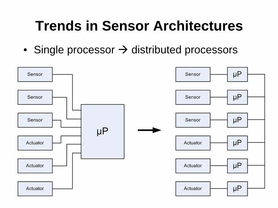
Trends in Sensor Architectures• Single processor distributed processors
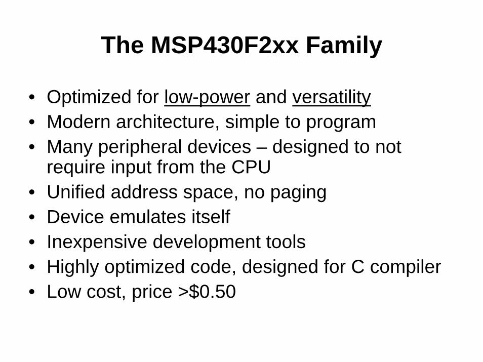
The MSP430F2xx Family
• Optimized for low-power and versatility• Modern architecture, simple to program• Many peripheral devices – designed to not
require input from the CPU• Unified address space, no paging• Device emulates itself• Inexpensive development tools• Highly optimized code, designed for C compiler• Low cost, price >$0.50

MSP430F2xx Architecture
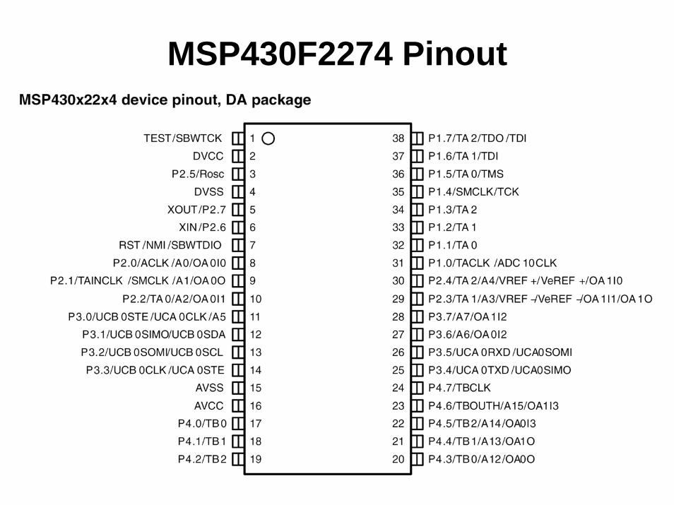
MSP430F2274 Pinout
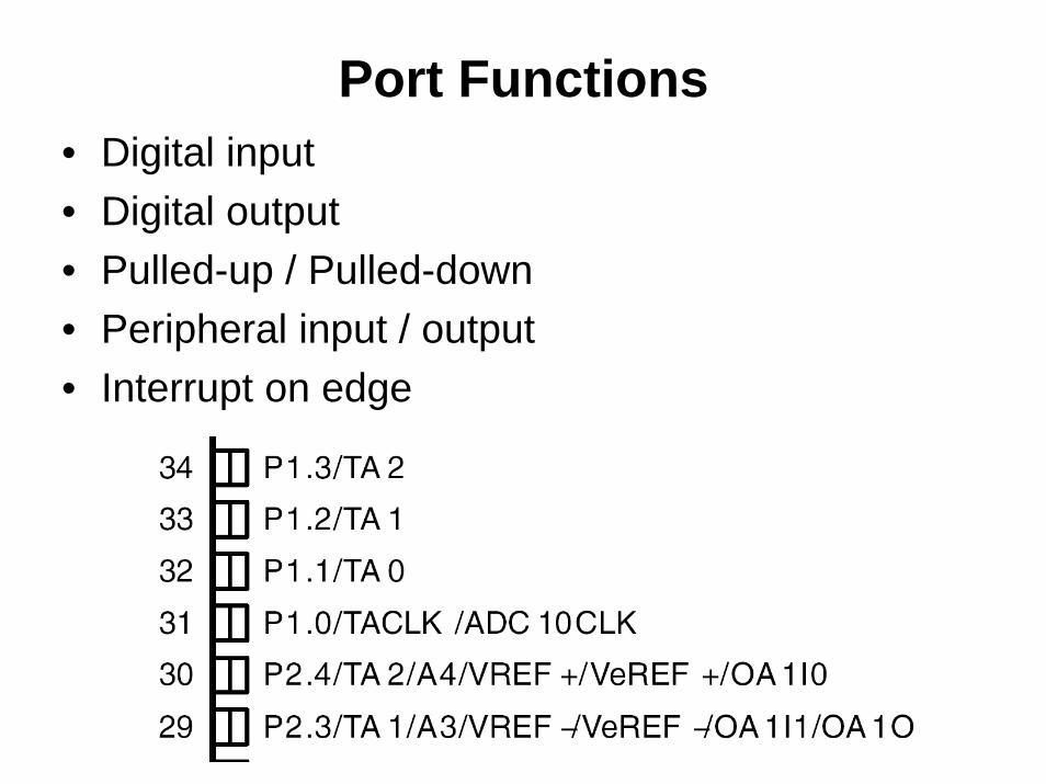
Port Functions• Digital input• Digital output• Pulled-up / Pulled-down• Peripheral input / output• Interrupt on edge
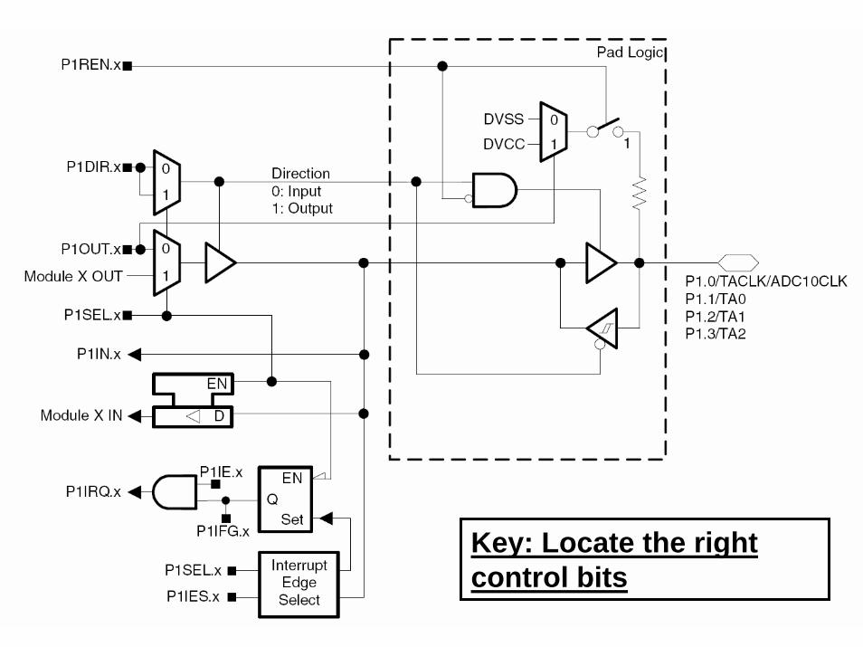
Key: Locate the right control bits
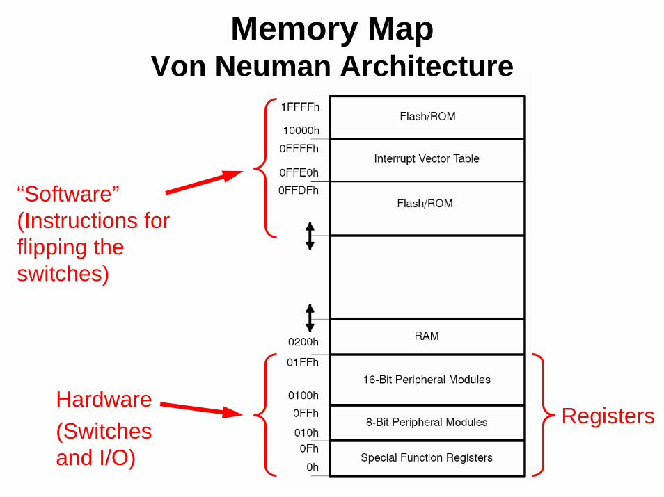
Memory MapVon Neuman Architecture
Hardware(Switches and I/O)
“Software” (Instructions for flipping the switches)
Registers

Hex Numbers and MemoryMSP430 Memory
• 8-bit addressing resolution

The Header File (msp430x22x4.h)• Assigns aliases for registers• Specific to each processor sub-group
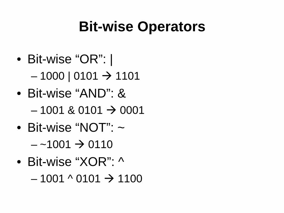
Bit-wise Operators
• Bit-wise “OR”: |– 1000 | 0101 1101
• Bit-wise “AND”: &– 1001 & 0101 0001
• Bit-wise “NOT”: ~– ~1001 0110
• Bit-wise “XOR”: ^– 1001 ^ 0101 1100

Assigning Individual Bits
• Assigning all 8-bits at once– P1OUT = 0xA7
• Assigning individual bits high– P1OUT |= 0x81
• Assigning individual bits low– P1OUT &= ~0x81
• Toggling individual bits– P1OUT ^= 0x81
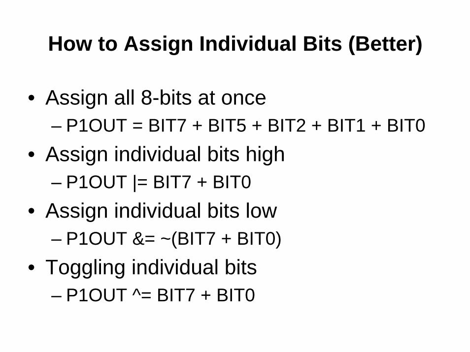
How to Assign Individual Bits (Better)
• Assign all 8-bits at once– P1OUT = BIT7 + BIT5 + BIT2 + BIT1 + BIT0
• Assign individual bits high– P1OUT |= BIT7 + BIT0
• Assign individual bits low– P1OUT &= ~(BIT7 + BIT0)
• Toggling individual bits– P1OUT ^= BIT7 + BIT0
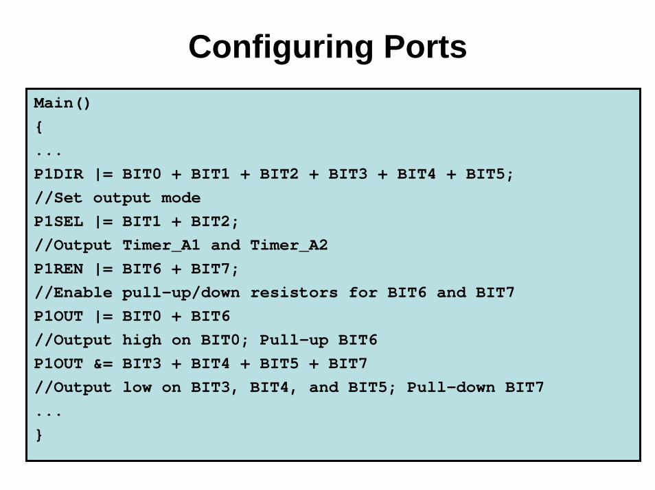
Configuring PortsMain(){...P1DIR |= BIT0 + BIT1 + BIT2 + BIT3 + BIT4 + BIT5; //Set output modeP1SEL |= BIT1 + BIT2;//Output Timer_A1 and Timer_A2P1REN |= BIT6 + BIT7;//Enable pull-up/down resistors for BIT6 and BIT7P1OUT |= BIT0 + BIT6//Output high on BIT0; Pull-up BIT6P1OUT &= BIT3 + BIT4 + BIT5 + BIT7//Output low on BIT3, BIT4, and BIT5; Pull-down BIT7...}
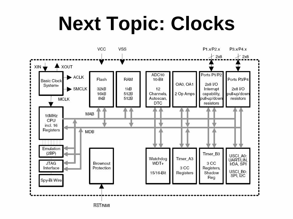
Next Topic: Clocks
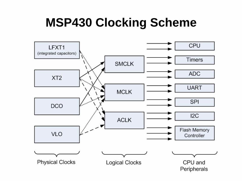
MSP430 Clocking Scheme

Crystal Oscillators
• Extremely accurate – standard frequency tolerance = 20ppm
• Many frequencies: 20kHz – GHz• Real Time Clock: 32.768kHz• Requires 2 external capacitors• LFXT1 has integrated capacitors• Ceramic resonator
– Smaller, cheaper cousin– Frequency tolerance ~ 0.5%
Photo removed due to copyright restrictions.

DCO (Digital Controlled Oscillator)• 0 to 16 MHz• Fast start-up <1uS• ±3% tolerance• ±6% tolerance over
temperature• Factory calibration in
Flash• Good enough for
UART• Application: watch
Images removed due to copyright restrictions.
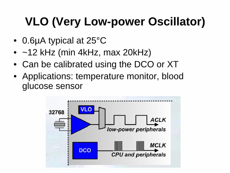
VLO (Very Low-power Oscillator)• 0.6µA typical at 25°C• ~12 kHz (min 4kHz, max 20kHz)• Can be calibrated using the DCO or XT• Applications: temperature monitor, blood
glucose sensor
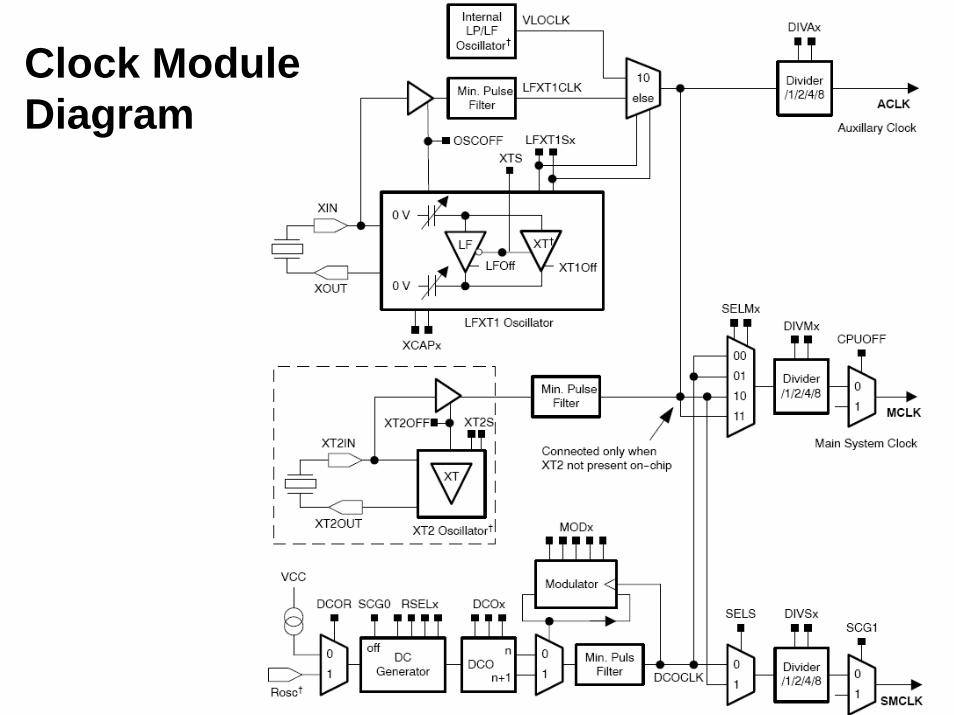
Clock Module Diagram
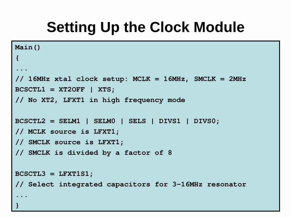
Setting Up the Clock ModuleMain(){...// 16MHz xtal clock setup: MCLK = 16MHz, SMCLK = 2MHzBCSCTL1 = XT2OFF | XTS;// No XT2, LFXT1 in high frequency mode
BCSCTL2 = SELM1 | SELM0 | SELS | DIVS1 | DIVS0;// MCLK source is LFXT1;// SMCLK source is LFXT1;// SMCLK is divided by a factor of 8
BCSCTL3 = LFXT1S1;// Select integrated capacitors for 3-16MHz resonator...}
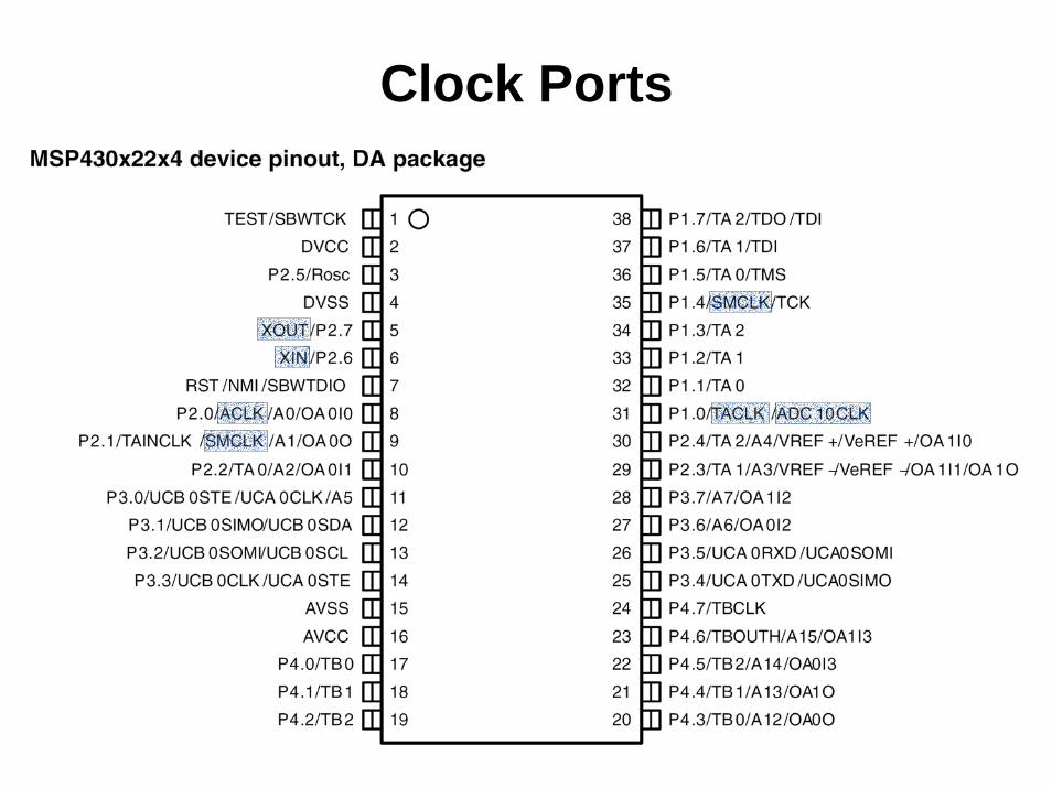
Clock Ports

Watch-dog Timer (WDT)• Designed to detect
– Software halting– Oscillator fault
• Active after device reset• “Kicking the dog” Reset the WDT• WDT runs down to 0 Processor reset• MSP430 WDT:
– Automatically switch clocks after failure– Password protected– Can be used as an ordinary timer

MSP430 WDT
WDTCTL = WDTPW + WDTHOLD;// Stop WDT
WDTCTL = WDTPW + WDTCNTCL;// Clear WDT
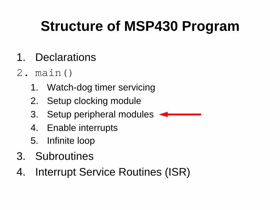
Structure of MSP430 Program
1. Declarations2. main()
1. Watch-dog timer servicing2. Setup clocking module3. Setup peripheral modules4. Enable interrupts5. Infinite loop
3. Subroutines4. Interrupt Service Routines (ISR)
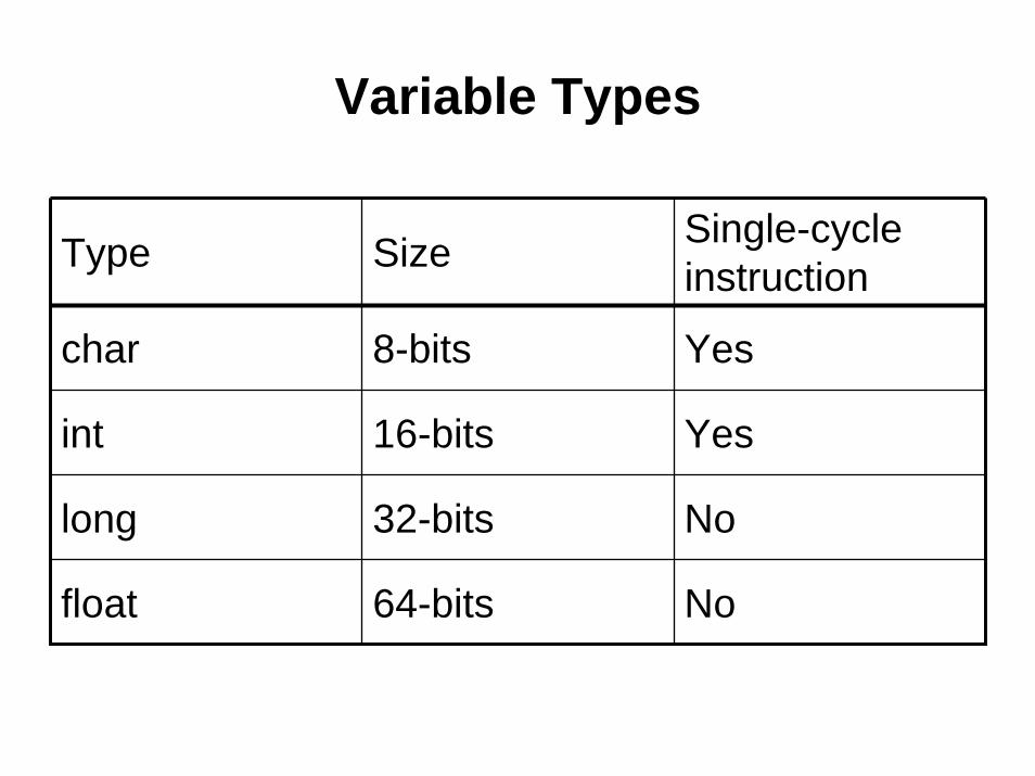
Variable Types
Type Size Single-cycle instruction
char 8-bits Yes
int 16-bits Yes
long 32-bits No
float 64-bits No

Number Representation
• One’s Complement • Two’s Complement
//One’s comp. definitionunsigned char var1unsigned int var2
//Two’s comp. definitionsigned char var1signed int var2
Always explicitly define signed / unsigned !!!
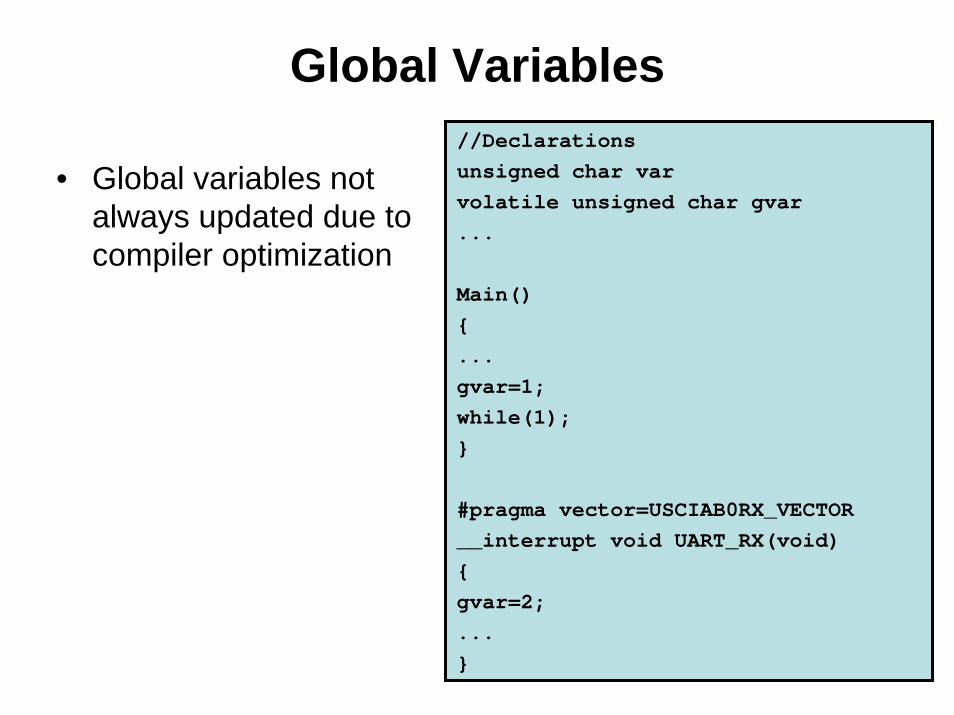
Global Variables
• Global variables not always updated due to compiler optimization
//Declarationsunsigned char varvolatile unsigned char gvar...
Main(){...gvar=1;while(1);}
#pragma vector=USCIAB0RX_VECTOR__interrupt void UART_RX(void){gvar=2;...}
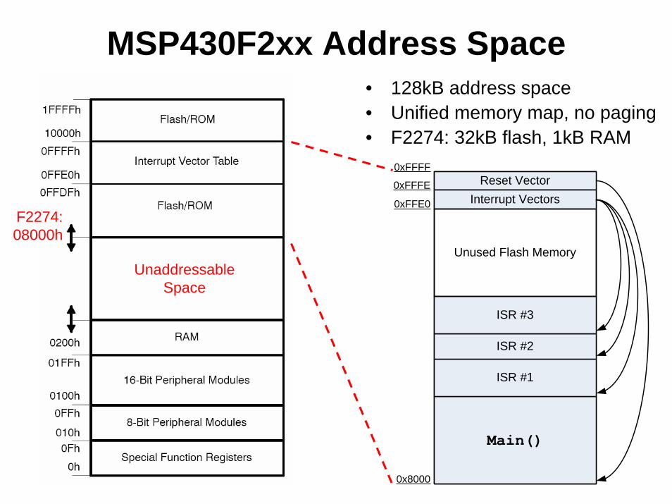
MSP430F2xx Address Space• 128kB address space• Unified memory map, no paging• F2274: 32kB flash, 1kB RAM
F2274: 08000h
Reset VectorInterrupt Vectors
Main()
ISR #1
ISR #2
ISR #3
Unused Flash Memory
0x8000
0xFFFF
0xFFFE
0xFFE0
UnaddressableSpace

Embedded Programming Styles
• Simple– Poll for events in main()
• Interrupt-driven– Code reside in the ISR– Used for handling a single interrupt source
• Event-driven– ISR sets flags for events– main()poll for flags and services them– Used for handling multiple interrupts sources
Components for Microprocessor Programming
• ICE – In-Circuit Emulator– Flash Emulation Tool (FET)– JTAG– Spy-Bi-Wire (2-wire JTAG)
• Bootloader– Rewrite flash via RS232– Password protected
• IDE – Integrated Development Environment– Editor, compiler, debugger
• Libraries for each microprocessor
Image removed due to copyright restrictions.

Brownout Detector and SVS• Brownout detector triggers a POR when supply voltage drops below 1.8V• SVS (Supply Voltage Supervisor) – Comparator-based (flash) ADC

Timer Related I/O
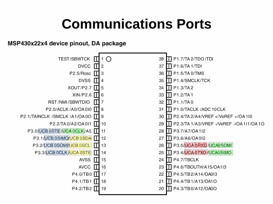
Communications Ports
Start / Reset Sequence
• PUC (Power Up Clear)• POR (Power On Reset)
Example C Code