lecture – 5 assembly language programming 1. outline bcd addition and subtraction binary to bcd...
TRANSCRIPT

1
Lecture – 5
Assembly Language Programming

2
Outline
• BCD addition and subtraction
• Binary to BCD conversion
• BCD to binary conversion
• Multiplication and division
• Time delays

3
BCD arithmetic
• Whenever data are entered from a keypad or keyboard, the number is in BCD or ASCII format.
• These BCD or ASCII numbers can be converted to binary, but again it requires time and a multiply instruction.
• Because the PlC microcontroller provides only one of the two instructions (multiply and divide) needed for the conversion of numbers between binary and BCD, the numbers often remain in the BCD format.

4
BCD addition (1)
• To perform BCD addition, an instruction called decimal adjust WREG (DAW) is provided for the conversion.
• The DAW instruction corrects the result of a BCD packed (two digits per byte) addition.
• This instruction is required because the microcontroller adds only binary numbers.
• The DAW instruction performs tests after an addition of packed BCD numbers to correct the sum to a valid BCD number in WREG.

5
BCD addition (2)
• The tests are as follows: – If the rightmost half-byte is greater than 9 or DC = 1, add 0x06– If the leftmost half-byte is greater than 9 or C = 1, add 0x60
• The DAW instruction adds 0x00,0x06,0x60, or 0x66 to WREG to correct the result after a packed BCD addition.
• If the result is greater than 100 BCD, the carry bit (C) is set to indicate the l00-bit position in the result.
• Therefore, if 99 BCD and 05 BCD are added, the result is 04 BCD with C set to a one to indicate the 100 after the DAW instruction executes.

6
Example 1
• Suppose that the 4-digit packed BCD number in access file registers 0x10 and 0x11 are added to the 4-digit packed BCD number in access file registers 0x20 and 0x21.
7
BCD subtraction
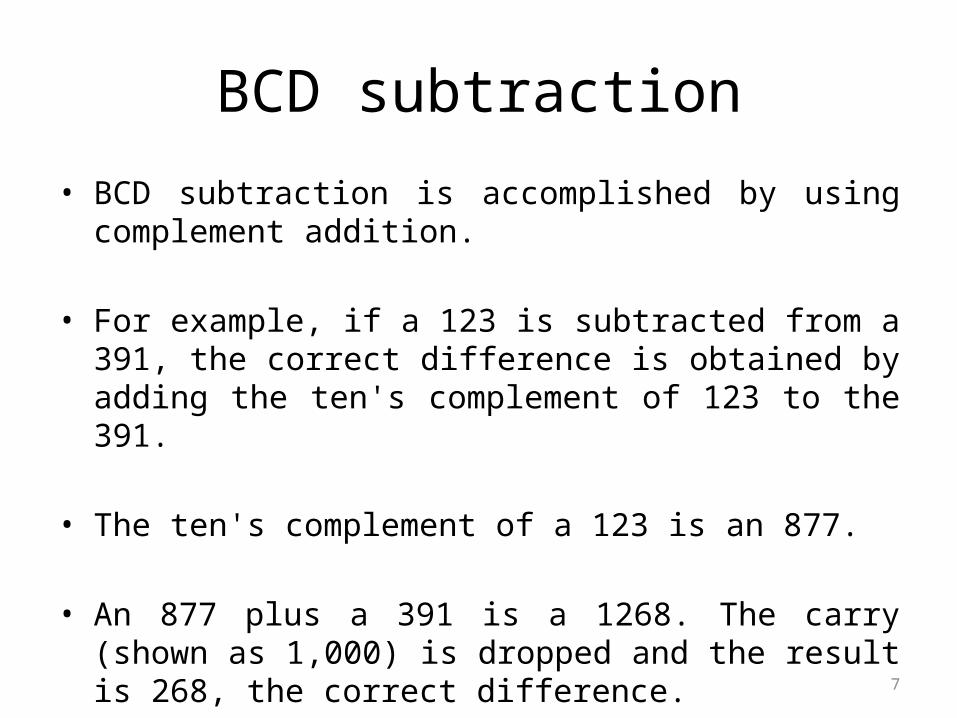
• BCD subtraction is accomplished by using complement addition.
• For example, if a 123 is subtracted from a 391, the correct difference is obtained by adding the ten's complement of 123 to the 391.
• The ten's complement of a 123 is an 877.
• An 877 plus a 391 is a 1268. The carry (shown as 1,000) is dropped and the result is 268, the correct difference.
8
Binary to BCD conversion
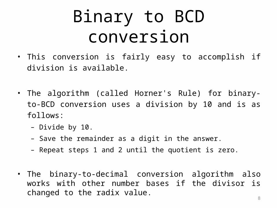
• This conversion is fairly easy to accomplish if division is available.
• The algorithm (called Horner's Rule) for binary-to-BCD conversion uses a
division by 10 and is as follows:
– Divide by 10.
– Save the remainder as a digit in the answer.
– Repeat steps 1 and 2 until the quotient is zero.
• The binary-to-decimal conversion algorithm also works with other number bases if the divisor is changed to the radix value.
• This algorithm is used to convert to any number base by changing the divisor to the radix number.

9
Example 2
• Suppose that a 0110 01112 must be converted to a series of
BCD digits.
_________________________
• If 0110 01112 is divided by 10102, a quotient of 10102 and a
remainder of 00112 is obtained. The 00112 is the least
significant digit of the result. Because the quotient of 10102 is
not zero, divide by 10102 again. This time we obtain a quotient
of 00012 and a remainder of 00002, Again, 00012 is divided by
10102 and a quotient of 00002 with a remainder of 00012 is
obtained. The result is 103, but the order in which the number
is returned is reversed.

10
BCD to Binary
• Converting from a BCD number to binary requires multiplication instead of division.
• The algorithm for the conversion is as follows:
- multiply the most significant digit of the BCD by decimal ten, then
- add the product to the least significant digit.
• As with the binary-to-decimal conversion algorithm, this algorithm also works for any number base by changing the multiplication number of 10 to the radix number. For example, if a string of octal digits exists, multiply by 8.
11
Example 3
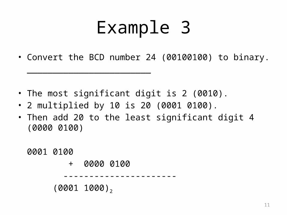
• Convert the BCD number 24 (00100100) to binary.
________________________
• The most significant digit is 2 (0010).• 2 multiplied by 10 is 20 (0001 0100).• Then add 20 to the least significant digit 4 (0000 0100)
0001 0100
+ 0000 0100
----------------------
(0001 1000)2

12
Multiplication
• The instruction set includes a multiplication instruction, but it is
limited to 8-bit multiplication.
• BUT, there are times when wider multiplication is required.
• Multiplication is a series of shifts and additions in the binary number
system.
• The algorithm requires a product that is twice the width of the
multiplier and multiplicand.
• For instance, a 16-bit multiplication requires a 32-bit product.

13
Multiplication
• The software algorithm for a 16-bit unsigned multiplication is:
1. Clear the 32-bit product.
2. Shift the multiplier right.
3. If the carry is set, add the multiplicand to the product.
4. If the multiplier is zero, end the function.
5. Shift the multiplicand left one place.
6. Repeat steps 2 through 5

14
Clear the 32-bit product
Shift the multiplier right
Is C=1
add the multiplicand to the product
Is the multiplier
= 0
Multiplication flow chart
END
Shift the multiplicand left
Yes
YesNo
No

15
Example 4
• Multiply 2 (00000010) by 4 (00000100).
1. multiplier = shift right (00000010), carry is zero
multiplicand = shift left (00000100)
product = 00000000
2. multiplier = shift right (00000001), carry is zero
multiplicand = shift left (00001000)
product = 00000000
3. multiplier = shift right (00000000), carry is set
multiplicand = (00001000)
product = 00001000

16
Division
• There is no instruction for division. If a division is required, an algorithm is available to accomplish it.
• we can write a program to perform division by repeated subtraction.
• In 8-bit division, the numerator is placed in a register (register1) and the denominator is subtracted from it repeatedly.
• The quotient is the number of times we subtracted and the reminder is the in the register (register1) after completion.

17
Example 5
MYQ RES 1
MYNMB RES 1
MYDEN RES 1
MOVLW MYDEN ; put the divisor in w
B1 INCF MYQ ; increment the
quotient SUBWF MYNMB,F ; (dividend- divisor)
BC B1 ; if carry=1 branch to B1
DECF MYQ, F ; decrement the quotient

18
Time delays (1)
• Many applications for a microcontroller require time delays.
• To start with, examine the simple time delay function:
• The contents of WREG are decremented and if the result is zero, a return
occurs.
• If the result is not zero, WREG is again decremented.
• This is simple and also quite short, and has a predictable execution time
determined by how many times the WREG is decremented.

19
Time delays (2)
• The amount of time required to execute this procedure is the number of instruction cycles required for the CALL and RETURN plus the number of instruction cycles required for WREG to decrement to zero.
• The decrement of WREG is accomplished by the DECFSZ followed by a BRA instruction. The CALL and RETURN instructions each require two instruction cycles for a total of four instruction cycles. The DECFSZ instruction requires one instruction cycle and the BRA instruction requires two instruction cycles.
• The following equation is for the number of instruction cycles required for
this function:
Clocks = 4 + WREG * 3 OR WREG = (Clocks - 4) / 3
20
Time delays (3)
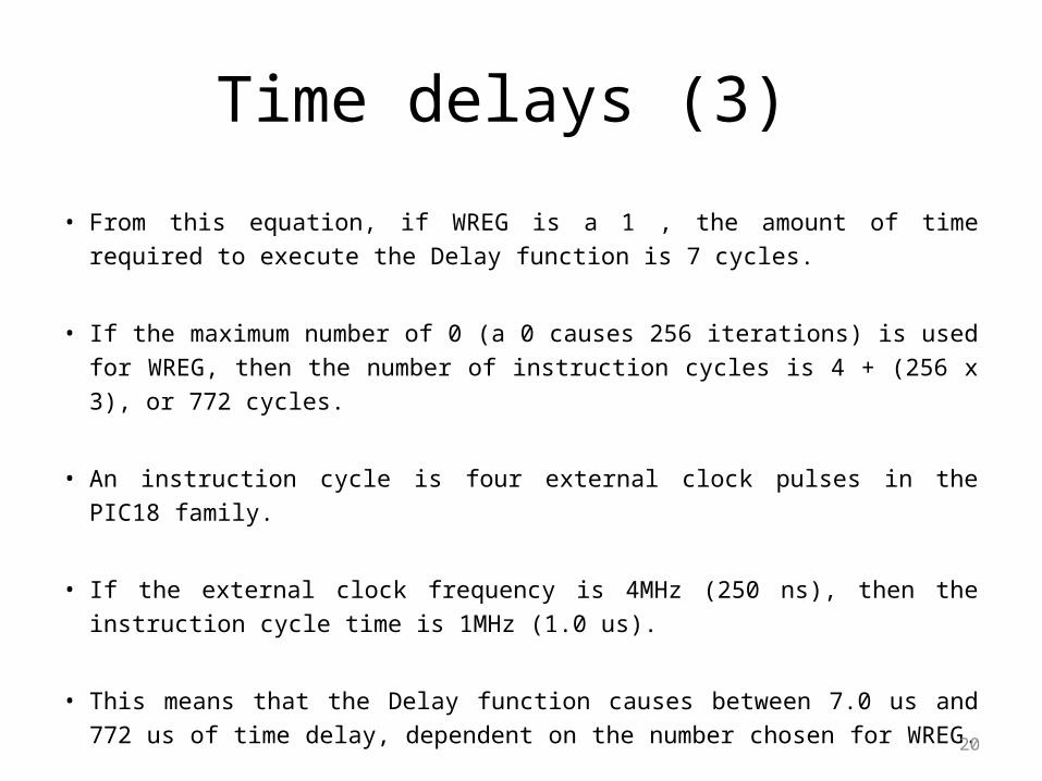
• From this equation, if WREG is a 1 , the amount of time required to execute
the Delay function is 7 cycles.
• If the maximum number of 0 (a 0 causes 256 iterations) is used for WREG,
then the number of instruction cycles is 4 + (256 x 3), or 772 cycles.
• An instruction cycle is four external clock pulses in the PIC18 family.
• If the external clock frequency is 4MHz (250 ns), then the instruction cycle
time is 1MHz (1.0 us).
• This means that the Delay function causes between 7.0 us and 772 us of time
delay, dependent on the number chosen for WREG.
21
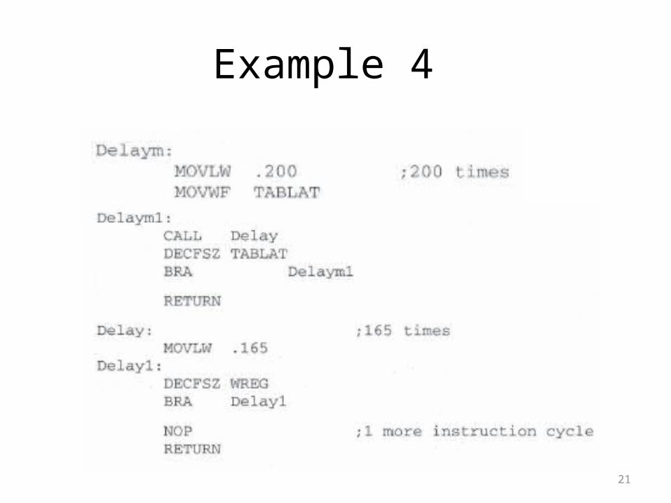
Example 4

22
Example 4
• Here a count of 165 is chosen for WREG. At a 4-MHz external clock, this gives us a delay time of 165 x 3 + 4 or 499 us (round that to 500 us for this example).
• If exactly 500 us is needed, a NOP (no operation) instruction (a NOP requires 1 instruction cycle to perform no operation) is added to the Delay function just before the RETURN.
• If we execute the 500 us delay 200 times, a time delay of exactly 100 ms is obtained.
• Of course, the accuracy of this delay depends on the accuracy of the clocking source.

23
Summary• Binary-coded decimal (BCD) addition and subtraction use the DAW
instruction to correct the result after a BCD addition. For a BCD subtraction, ten's complement addition is used to form the difference and use the DAW instruction.
• The DAW instruction corrects the result of a BCD addition by examining the carry and digit carry status register bits as well as the values in both digits of the result. The result determines whether a 0x00,0x06, 0x60, or 0x66 is added for the correction.
• Binary-to-decimal conversion requires a division by ten. The algorithm used for the conversion is called the Horner's Rule. This algorithm also functions for converting a binary number to any number base by changing the divide by number.

24
Summary
• Decimal-to-binary conversion is accomplished by multiplication by ten. This conversion also converts from any number base to binary by changing the multiplication number to the number base.
• Time delays are often produced by software. This is accomplished because the amount of time required to execute an instruction is known. Therefore, accurate time delays are constructed with programmed loops.

25
Questions
1. Determine the number added by a DAW instruction for the following packed BCD additions:
a. 03 + 08
b. 10 + 28
c. 92 + 99
d. 92 + 90
__________________________
(a) 0x06
(b) 0x00
(c) 0x66
(d) 0x60

26
Questions
2. Develop a function that squares the number in WREG, returning the result in WREG as 8-bit result.
________________________
SQR:
MOVWF PRODL ;copy WREG into PRODL
MULWF PRODL ;form product
MOVF PRODL ;copy product into WREG
RETURN

Questions
27
3. Develop a series of functions for a 100 ms time delay called D100 and 1 second time delay called D1 if the microcontroller clock is 20 MHz. _____________________________
Delay: .165 times (100 μs) MOVLW .165 Delay1: DECFSZ WREG BRA Delay1 RETURN Delaym: MOVLW .100 ;100 times (10 ms) MOVWF TABLAT Delaym1: CALL Delay DECFSZ TABLAT BRA Delaym1 RETURN
D100: MOVLW .10 ;10 times (100 ms) MOVWF PRODL D100a: CALL Delaym DECFSZ PRODL BRA D100a RETURN D1: MOVLW .10 ;10 times (1 second) MOVWF PRODH D1a: CALL D100 DECFSZ PRODH BRA D1a RETURN