lecture 4 - jyväskylän yliopistousers.jyu.fi/~loberg/fyse420slides/fyse420lecture4.… · ·...
TRANSCRIPT
FYSE420 DIGITAL ELECTRONICS
Lecture 4
1
DIGITAL LOGIC
CIRCUIT ANALYSIS
& DESIGN Nelson, Nagle, Irvin, Carrol
ISBN 0-13-463894-8
DIGITAL DESIGN Morris Mano
Fourth edition
ISBN 0-13-198924-3
Digital Design Principles and Practices
Fourth edition
Wakerly John F.
ISBN 0-13-186389-4
[1]
[2]
[3]
2
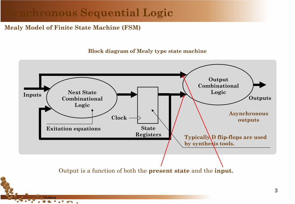
Mealy Model of Finite State Machine (FSM)
Block diagram of Mealy type state machine
Output is a function of both the present state and the input.
Next State
Combinational
Logic
Output
Combinational
Logic
State
Registers
Clock
Outputs Inputs
Exitation equations
Asynchronous
outputs
Typically D flip-flops are used
by synthesis tools.
Synchronous Sequential Logic
3
©Loberg
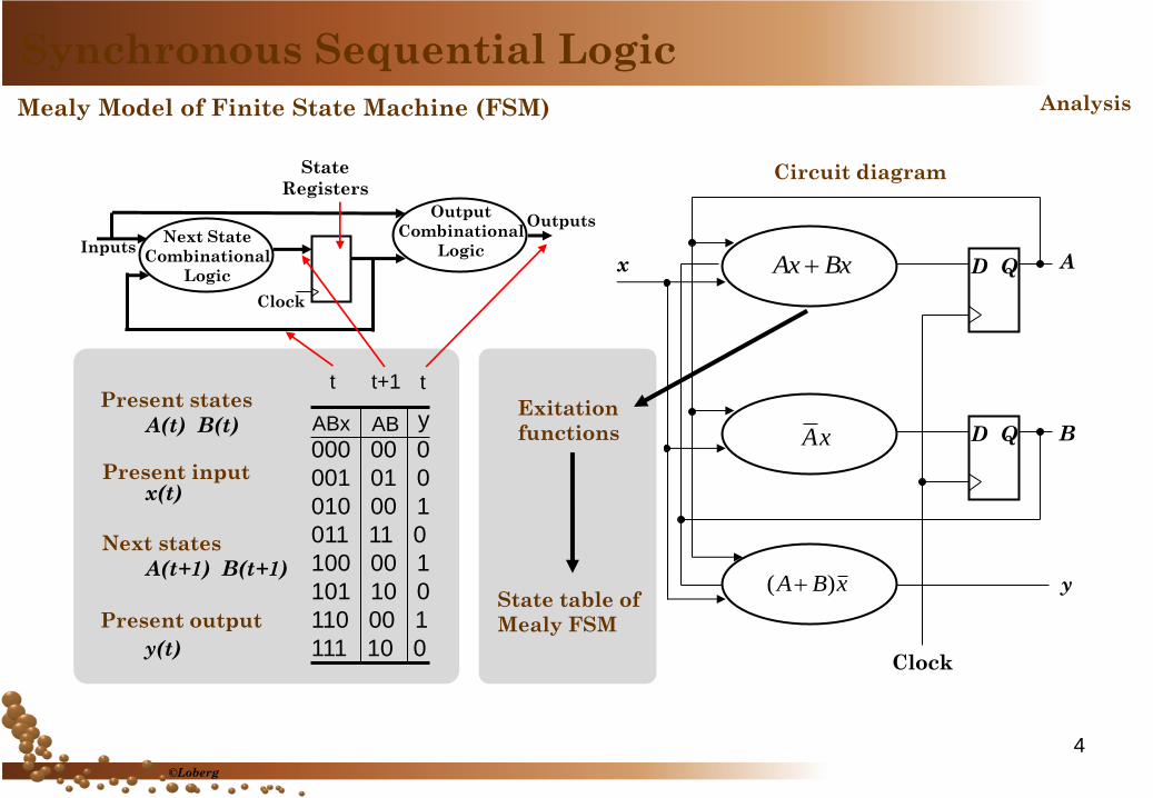
Next State
Combinational
Logic
Output
Combinational
Logic
State
Registers
Clock
Outputs
Inputs
000 00 0
001 01 0
010 00 1
011 11 0
100 00 1
101 10 0
110 00 1
111 10 0
ABx AB y
t t+1 t Present states
A(t) B(t)
Present input x(t)
Next states
A(t+1) B(t+1)
Present output
y(t)
Circuit diagram
Analysis
D Q
D Q
BxAx
xA
A
B
y xBA )(
Clock
x
Synchronous Sequential Logic
Mealy Model of Finite State Machine (FSM)
Exitation
functions
State table of
Mealy FSM
4
©Loberg
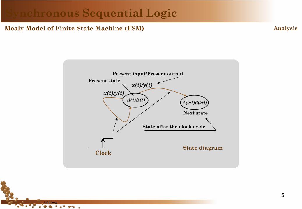
State diagram
A(t)B(t) A(t+1)B(t+1)
x(t)/y(t) Present state
Next state
Present input/Present output
State after the clock cycle
x(t)/y(t)
Clock
Synchronous Sequential Logic
Mealy Model of Finite State Machine (FSM) Analysis
5
©Loberg
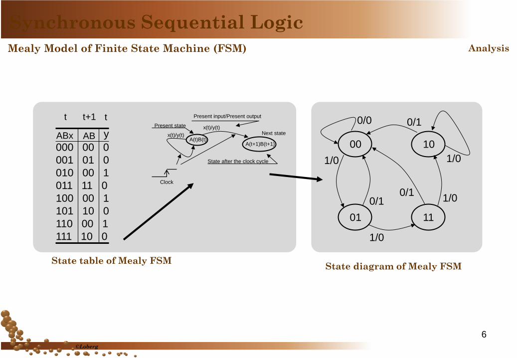
00
11 01
10
0/0 0/1
1/0
1/0 0/1
1/0
1/0
0/1
State diagram of Mealy FSM
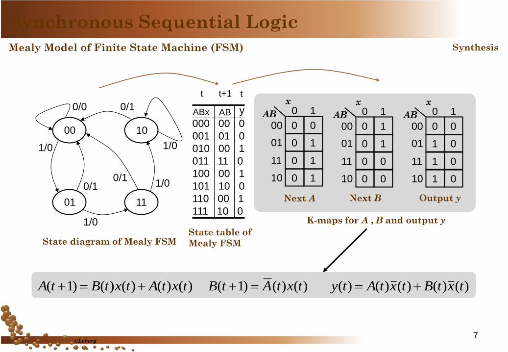
000 00 0
001 01 0
010 00 1
011 11 0
100 00 1
101 10 0
110 00 1
111 10 0
ABx AB y
t t+1 t
State table of Mealy FSM
A(t)B(t) A(t+1)B(t+1)
x(t)/y(t) Present state
Next state
Present input/Present output
State after the clock cycle
x(t)/y(t)
Clock
Synchronous Sequential Logic
Mealy Model of Finite State Machine (FSM) Analysis
6
©Loberg
000 00 0
001 01 0
010 00 1
011 11 0
100 00 1
101 10 0
110 00 1
111 10 0
ABx AB y
t t+1 t
00
11 01
10
0/0 0/1
1/0
1/0 0/1
1/0
1/0
0/1
State diagram of Mealy FSM State table of
Mealy FSM
0 0
0 1
0 1
0 1
x 0 1
00
01
11
10
AB
0 1
0 1
0 0
0 0
x 0 1
00
01
11
10
AB
0 0
1 0
1 0
1 0
x 0 1
00
01
11
10
AB
Next A Next B Output y
K-maps for A , B and output y
)()()()()1( txtAtxtBtA )()()1( txtAtB )()()()()( txtBtxtAty
Synchronous Sequential Logic
Mealy Model of Finite State Machine (FSM) Synthesis
7 ©Loberg
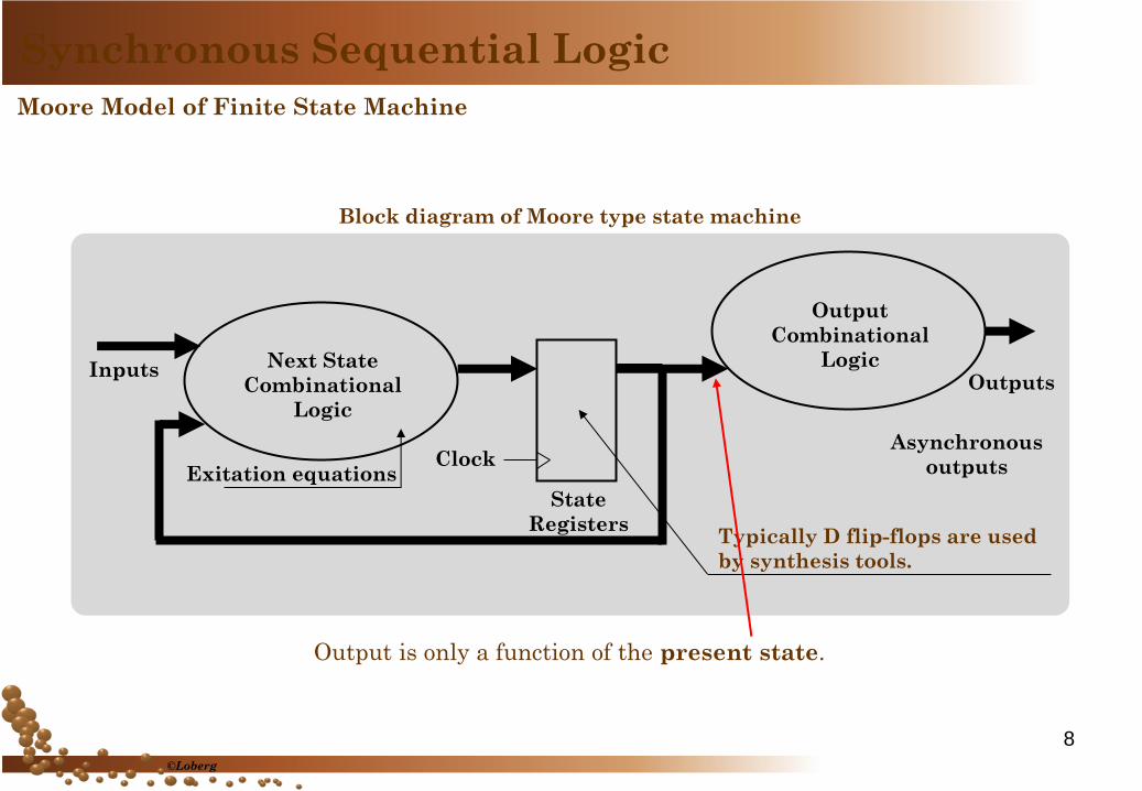
Moore Model of Finite State Machine
Block diagram of Moore type state machine
Next State
Combinational
Logic
Output
Combinational
Logic
State
Registers
Clock
Outputs Inputs
Exitation equations
Output is only a function of the present state.
Asynchronous
outputs
Typically D flip-flops are used
by synthesis tools.
Synchronous Sequential Logic
8
©Loberg
T Q
T Q
Bx
x
A
B
y AB
Clock
x
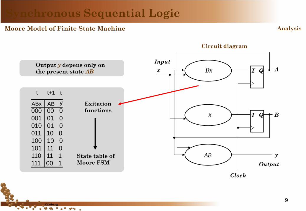
Circuit diagram
State table of
Moore FSM
Exitation
functions 000 00 0
001 01 0
010 01 0
011 10 0
100 10 0
101 11 0
110 11 1
111 00 1
ABx AB y
t t+1 t
Output y depens only on
the present state AB
Synchronous Sequential Logic
Moore Model of Finite State Machine Analysis
Input
Output
9 ©Loberg
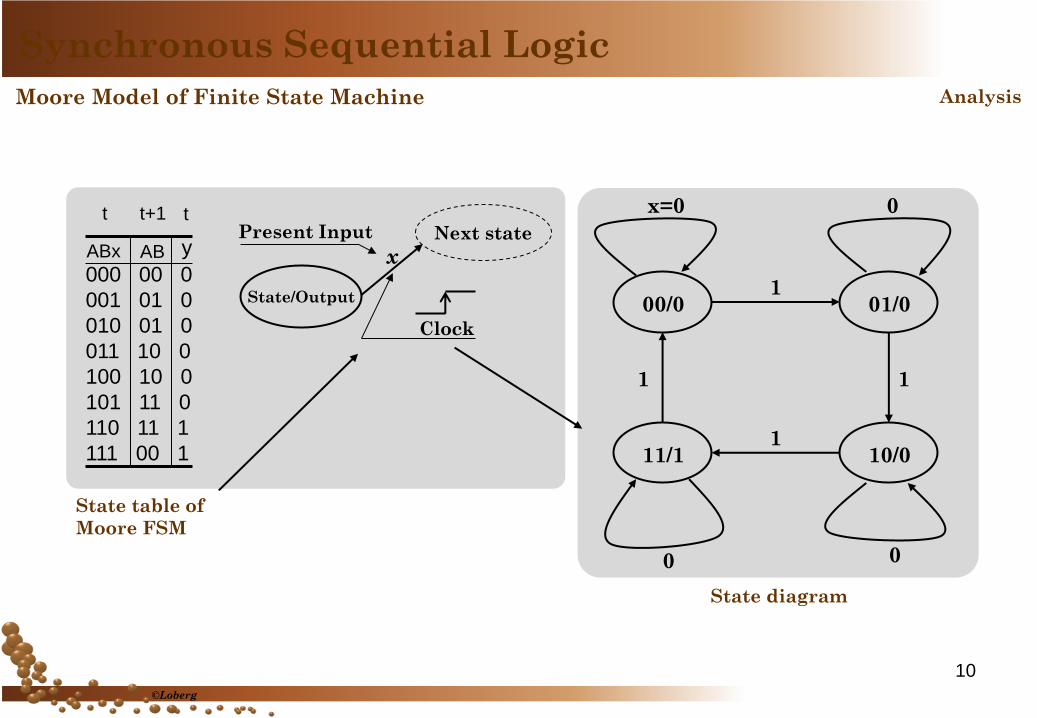
State table of
Moore FSM
000 00 0
001 01 0
010 01 0
011 10 0
100 10 0
101 11 0
110 11 1
111 00 1
ABx AB y
t t+1 t
State/Output
x
Clock
Present Input Next state
00/0
11/1
01/0
10/0
x=0
0 0
0
1
1
1
1
State diagram
Synchronous Sequential Logic
Analysis Moore Model of Finite State Machine
10
©Loberg
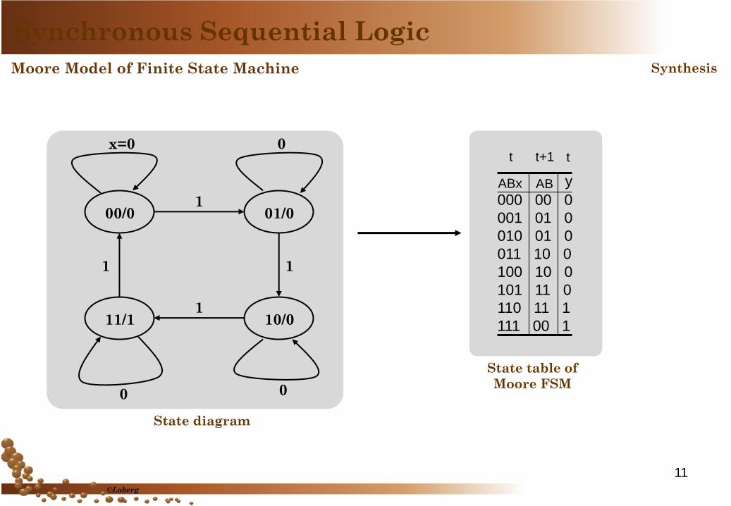
000 00 0
001 01 0
010 01 0
011 10 0
100 10 0
101 11 0
110 11 1
111 00 1
ABx AB y
t t+1 t
State table of
Moore FSM
Synchronous Sequential Logic
Moore Model of Finite State Machine Synthesis
00/0
11/1
01/0
10/0
x=0
0 0
0
1
1
1
1
State diagram
11
©Loberg
0 0
0 1
0 1
0 0
x 0 1
00
01
11
10
AB
0 1
0 1
0 1
0 1
x 0 1
00
01
11
10
AB
0 0
0 0
1 1
0 0
x 0 1
00
01
11
10
AB
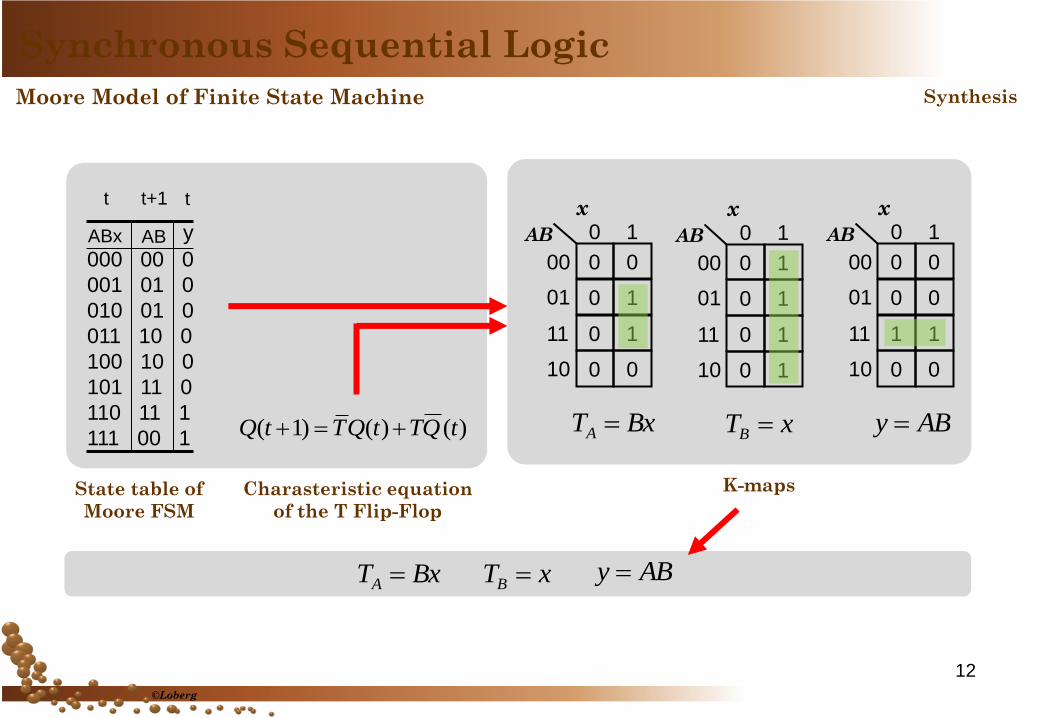
000 00 0
001 01 0
010 01 0
011 10 0
100 10 0
101 11 0
110 11 1
111 00 1
ABx AB y
t t+1 t
State table of
Moore FSM
Charasteristic equation
of the T Flip-Flop
)()()1( tQTtQTtQ BxTA xTB ABy
K-maps
BxTA xTB ABy
Synchronous Sequential Logic
Moore Model of Finite State Machine Synthesis
12
©Loberg
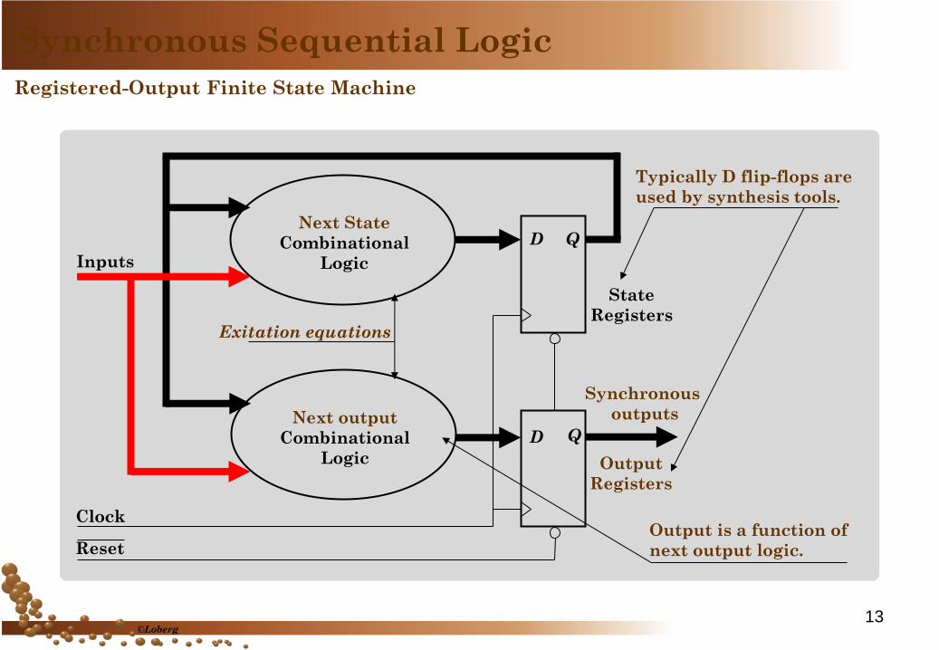
Registered-Output Finite State Machine
Output is a function of
next output logic.
D
D Next output
Combinational
Logic
State
Registers
Clock
Synchronous
outputs
Inputs
Next State
Combinational
Logic
Output
Registers
Exitation equations
Reset
Q
Q
Typically D flip-flops are
used by synthesis tools.
Synchronous Sequential Logic
13 ©Loberg
S0/0
S4/0
S3/1
S1/0
S2/1
x=0 0
1
1
0
1
1
1
0
0
S0/_
S4
S3
S1/_
S2
x=0/0
0/0
1/1
1/1
0/0
1/0
1/0
1/0
0/0
0/1
State diagram Registered-Output FSM
Use Flip-Flop exitation
tables
Implementation
Synchronous Sequential Logic
Registered-Output Finite State Machine Synthesis
State reduction
State assignment
K-maps
Present State/Output y(t)
1/0 Present Input x
Next Output Y(t+1)
To Next State
14
©Loberg
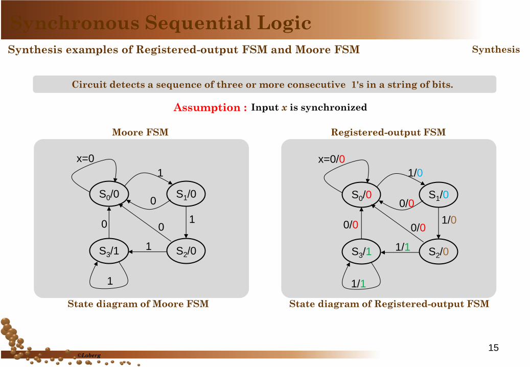
Synthesis examples of Registered-output FSM and Moore FSM
Circuit detects a sequence of three or more consecutive 1's in a string of bits.
Moore FSM Registered-output FSM
S0/0
S3/1 S2/0
S1/0
x=0
0
1
1
0
1
1
0
S0/0
S3/1 S2/0
S1/0
x=0/0
0/0
1/0
1/0
0/0
1/1
1/1
0/0
State diagram of Moore FSM State diagram of Registered-output FSM
Input x is synchronized
Synchronous Sequential Logic
Synthesis
Assumption :
15 ©Loberg

000 00 0
001 01 0
010 00 0
011 10 0
100 00 0
101 11 1
110 00 0
111 11 1
ABx AB Y
t t+1 t+1
000 00 0
001 01 0
010 00 0
011 10 0
100 00 0
101 11 0
110 00 1
111 11 1
ABx AB y
t t+1 t
State Table of
Moore FSM
State Table of
Registered-output FSM
Synchronous Sequential Logic
Synthesis Synthesis examples of Registered-output FSM and Moore FSM
Moore FSM Registered-output FSM
S0 = 00 = AB S1 = 01 = AB S2 = 10 = AB S3 = 11 = AB
S0/0
S3/1 S2/0
S1/0
x=0/0
0/0
1/0
1/0
0/0
1/1
1/1
0/0
S0/0
S3/1 S2/0
S1/0
x=0
0
1
1
0
1
1
0
16
©Loberg
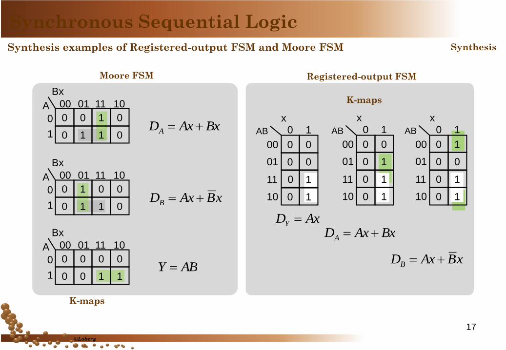
0 0
0 1
0 1
0 1
x 0 1
00
01
11
10
AB
0 1
0 0
0 1
0 1
x 0 1
00
01
11
10
AB
0 0
0 0
1
0 1
x 0 1
00
01
11
10
AB
0
AxDY BxAxDA
xBAxDB
0 0 1 0
0 1 1 0
00 01 11 10
0
1
A
Bx
0 1 0 0
0 1 1 0
00 01 11 10
0
1
A
Bx
0 0 0 0
0 0 1 1
00 01 11 10
0
1
A
Bx
BxAxDA
xBAxDB
ABY
K-maps
K-maps
Synchronous Sequential Logic
Synthesis Synthesis examples of Registered-output FSM and Moore FSM
Moore FSM Registered-output FSM
17
©Loberg
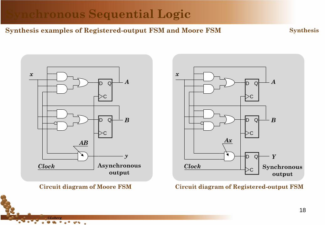
D Q
C
D Q
C
y
A
B
Clock
x
Asynchronous
output
Circuit diagram of Moore FSM
AB
D Q
C
D Q
C
D Q
C
Y
A
B
Clock
x
Synchronous
output
Circuit diagram of Registered-output FSM
Ax
Synchronous Sequential Logic
Synthesis Synthesis examples of Registered-output FSM and Moore FSM
18
©Loberg
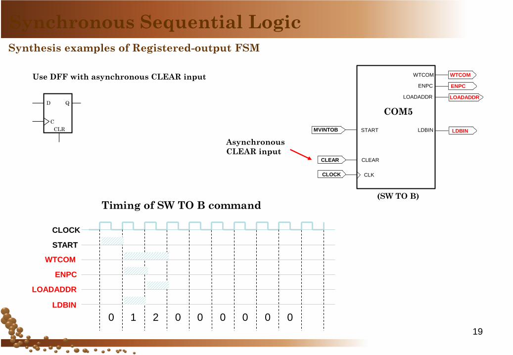
19
Synthesis examples of Registered-output FSM
Synchronous Sequential Logic
Timing of SW TO B command
CLOCK
LOADADDR
ENPC
START
0 1 2 0 0 0 0 0 0
LDBIN
WTCOM
(SW TO B)
CLOCK
CLEAR
MVINTOB
WTCOM
ENPC
LOADADDR
START
CLK
CLEAR
ENPC
LOADADDR
WTCOM
COM5
LDBIN LDBIN CLR
C
Q D
Use DFF with asynchronous CLEAR input
Asynchronous
CLEAR input
20
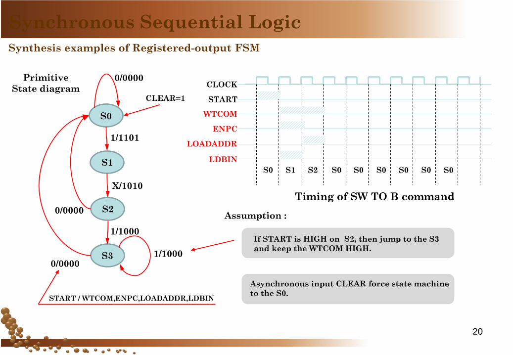
Synthesis examples of Registered-output FSM
Synchronous Sequential Logic
CLOCK
LOADADDR
ENPC
START
S0 S1 S2 S0 S0 S0 S0 S0 S0
LDBIN
WTCOM
Timing of SW TO B command
START / WTCOM,ENPC,LOADADDR,LDBIN
Primitive
State diagram
0/0000
0/0000
0/0000
1/1101
X/1010
1/1000
1/1000
CLEAR=1
S0
S1
S2
S3
Assumption :
If START is HIGH on S2, then jump to the S3
and keep the WTCOM HIGH.
Asynchronous input CLEAR force state machine
to the S0.
21
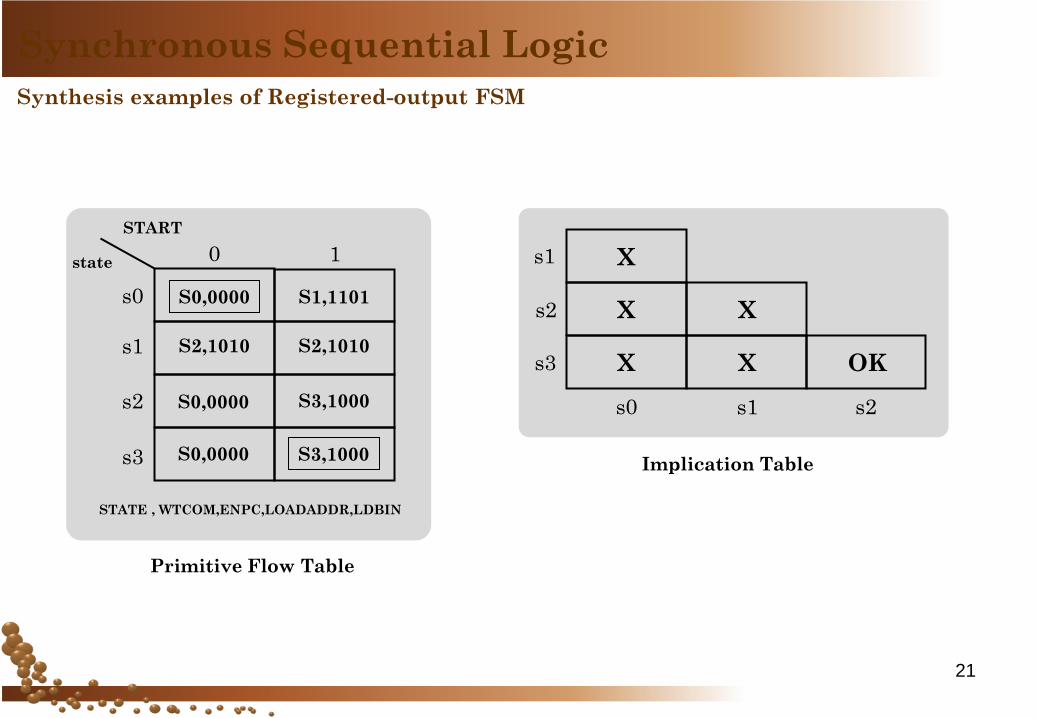
Synthesis examples of Registered-output FSM
Synchronous Sequential Logic
Primitive Flow Table
START
state
s0
0
s1
s2
s3
S0,0000
S3,1000
S1,1101
S0,0000
S2,1010
S0,0000
S2,1010
S3,1000
1
STATE , WTCOM,ENPC,LOADADDR,LDBIN
s2
s1
s0
s3
s2 s1
X
X
X
X
X
OK
Implication Table
22
Synthesis examples of Registered-output FSM
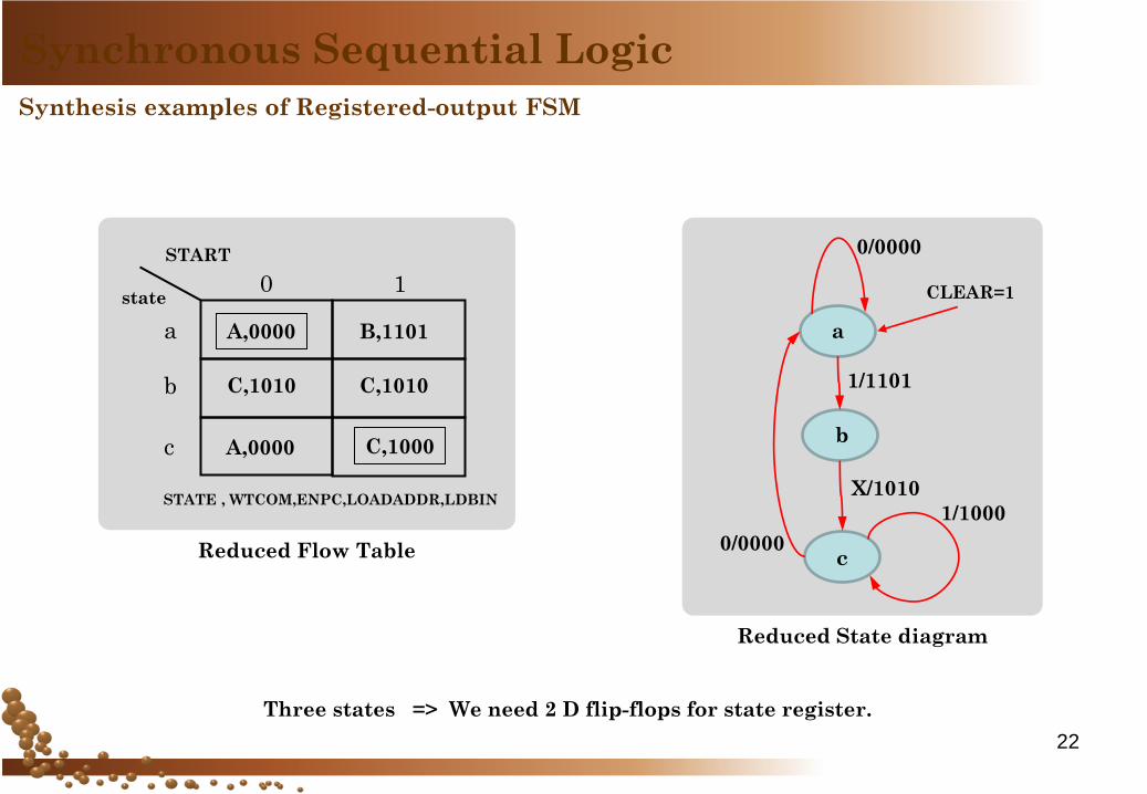
Synchronous Sequential Logic
Reduced State diagram
0/0000
0/0000
1/1101
X/1010
1/1000
CLEAR=1
a
b
c
Three states => We need 2 D flip-flops for state register.
START
state
a
0
b
c
A,0000 B,1101
A,0000
C,1010 C,1010
1
STATE , WTCOM,ENPC,LOADADDR,LDBIN
Reduced Flow Table
C,1000
23
Synthesis examples of Registered-output FSM
Synchronous Sequential Logic
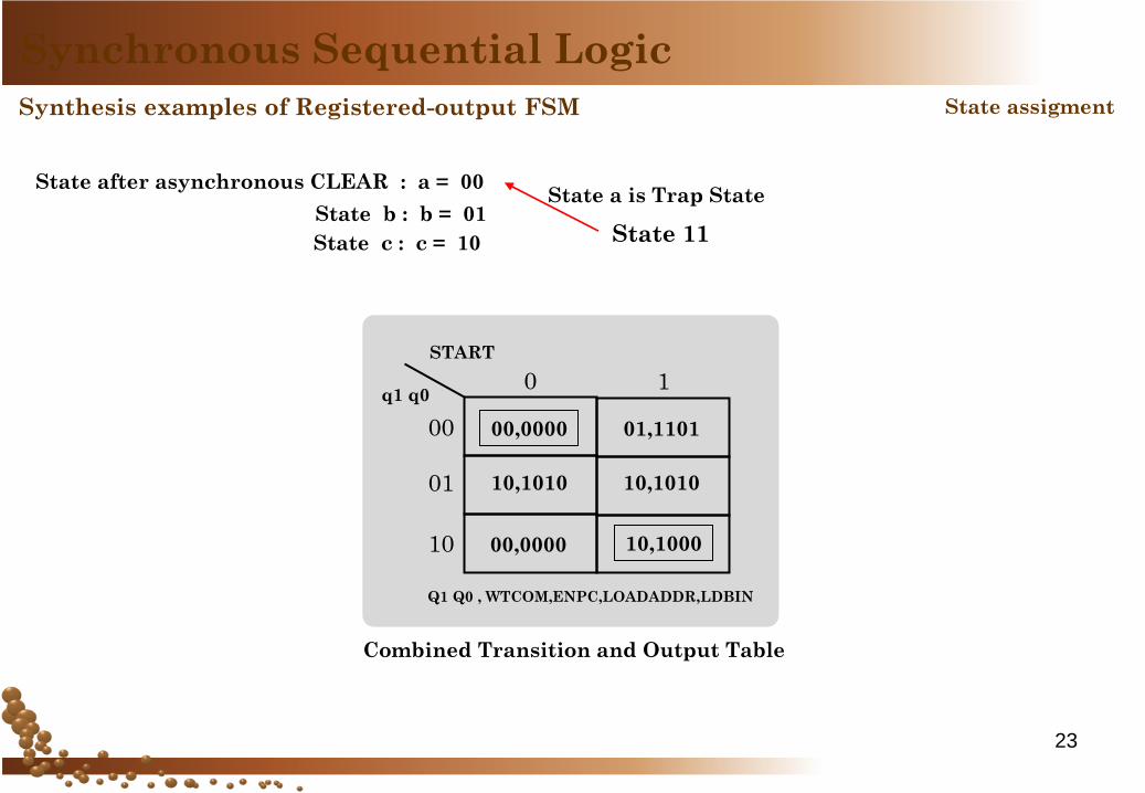
State assigment
State after asynchronous CLEAR : a = 00
State b : b = 01
State c : c = 10
State a is Trap State
START
q1 q0
00
0
01
10
00,0000 01,1101
00,0000
10,1010 10,1010
1
Q1 Q0 , WTCOM,ENPC,LOADADDR,LDBIN
Combined Transition and Output Table
10,1000
State 11
24
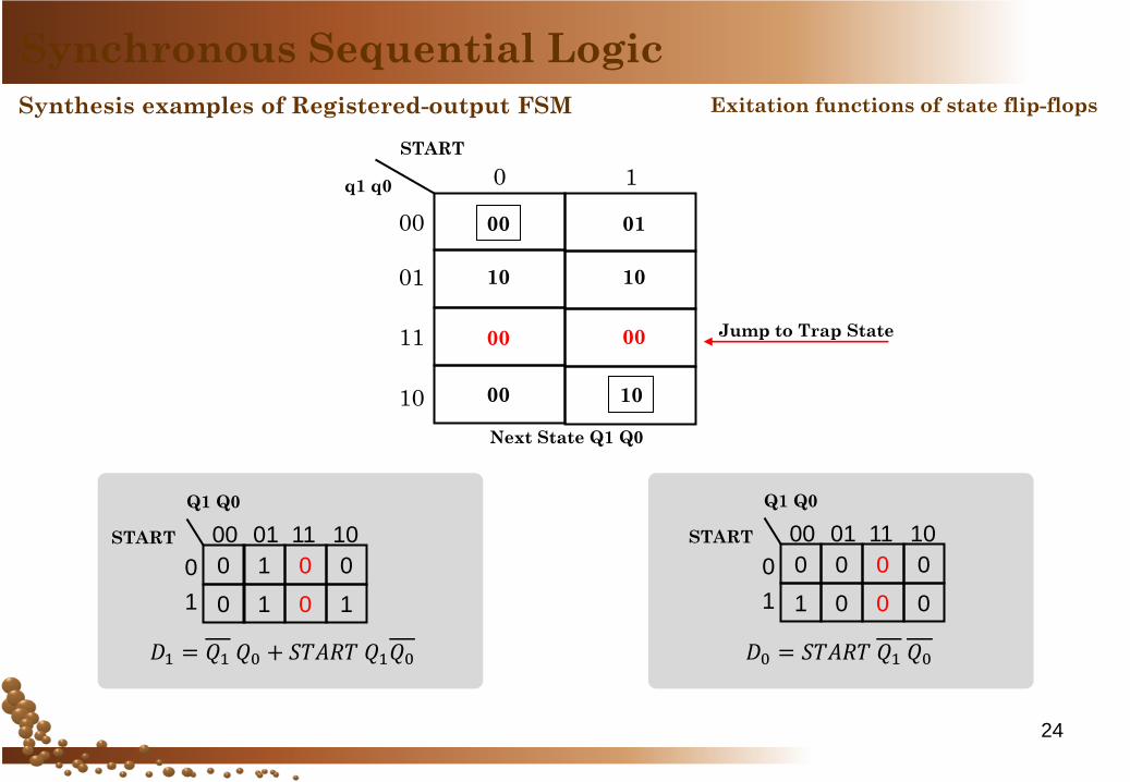
Synthesis examples of Registered-output FSM
Synchronous Sequential Logic
START
q1 q0
00
0
01
11
10
00
10
01
00
10
00
10
00
1
Next State Q1 Q0
Jump to Trap State
Exitation functions of state flip-flops
0 1 0 0
0 1 0 1
00 01 11 10
0
1
Q1 Q0
START
𝐷1 = 𝑄1 𝑄0 + 𝑆𝑇𝐴𝑅𝑇 𝑄1𝑄0
0 0 0 0
1 0 0 0
00 01 11 10
0
1
Q1 Q0
START
𝐷0 = 𝑆𝑇𝐴𝑅𝑇 𝑄1 𝑄0
25
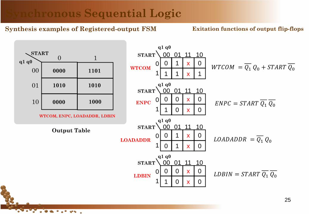
Synthesis examples of Registered-output FSM
Synchronous Sequential Logic
Exitation functions of output flip-flops
START
q1 q0
00
0
01
10
0000 1101
0000
1010 1010
1
WTCOM, ENPC, LOADADDR, LDBIN
Output Table
1000
0 1 x 0
1 1 x 1
00 01 11 10
0
1
START
q1 q0
0 0 x 0
1 0 x 0
00 01 11 10
0
1
START
q1 q0
0 1 x 0
0 1 x 0
00 01 11 10
0
1
START
q1 q0
0 0 x 0
1 0 x 0
00 01 11 10
0
1
START
q1 q0
WTCOM
ENPC
LOADADDR
LDBIN
𝑊𝑇𝐶𝑂𝑀 = 𝑄1 𝑄0 + 𝑆𝑇𝐴𝑅𝑇 𝑄0
𝐸𝑁𝑃𝐶 = 𝑆𝑇𝐴𝑅𝑇 𝑄1 𝑄0
𝐿𝑂𝐴𝐷𝐴𝐷𝐷𝑅 = 𝑄1 𝑄0
𝐿𝐷𝐵𝐼𝑁 = 𝑆𝑇𝐴𝑅𝑇 𝑄1 𝑄0

The End
26
©Loberg