lecture 4 b signalconditioning_ac bridge
TRANSCRIPT
Signal Conditioning for
Electronic Instrumentation AC Bridges
1
MCT 3332 : Instrumentation and Measurements Dr. Hazlina Md Yusof Department of Mechatronics Engineering International Islamic University Malaysia

Analog Signal Conditioning AC Bridges
2
• Used to measure inductance and capacitances • Applied in communication systems and complex
electronic circuits - Used for shifting phase, providing feedback paths for
oscillators or amplifiers, filtering out undesired signals and measuring the frequency of audio signals
• Operates on balanced condition - Reactance and resistive
components are balanced
Analog Signal Conditioning AC Bridges AC Bridge: Balance Condition
D
Z1Z2
Z4Z3
A C
D
B
I1 I2
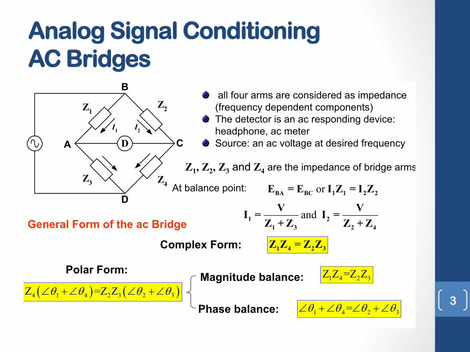
all four arms are considered as impedance (frequency dependent components)The detector is an ac responding device: headphone, ac meterSource: an ac voltage at desired frequency
General Form of the ac Bridge
Z1, Z2, Z3 and Z4 are the impedance of bridge arms
At balance point: orBA BC 1 1 2 2E = E I Z = I Z
and1 21 3 2 4
V V I = I =Z + Z Z + Z
V
1 4 2 3Z Z = Z Z
� � � �1 4 1 4 2 3 2 3Z Z =Z ZT T T T� �� � ��
Complex Form:
Polar Form: Magnitude balance:
Phase balance:
1 4 2 3Z Z =Z Z
1 4 2 3=T T T T� �� � ��3

Analog Signal Conditioning AC Bridges
4
Example The impedance of the basic ac bridge are given as follows:o
1
2
100 80 (inductive impedance)250 (pure resistance)
: � :
ZZ
Determine the constants of the unknown arm.
SOLUTION The first condition for bridge balance requires that
o3
4
400 30 (inductive impedance)unknown
� :
ZZ
2 34
1
250 400 1,000 100
Z ZZZ
u :
The second condition for bridge balance requires that the sum of the phase angles of opposite arms be equal, therefore
o4 2 3 1= 0 30 80 50T T T T� � �� �� � � �
Hence the unknown impedance Z4 can be written in polar form as o
4 1,000 50 : ��Z
Indicating that we are dealing with a capacitive element, possibly consisting of a series combination of at resistor and a capacitor.
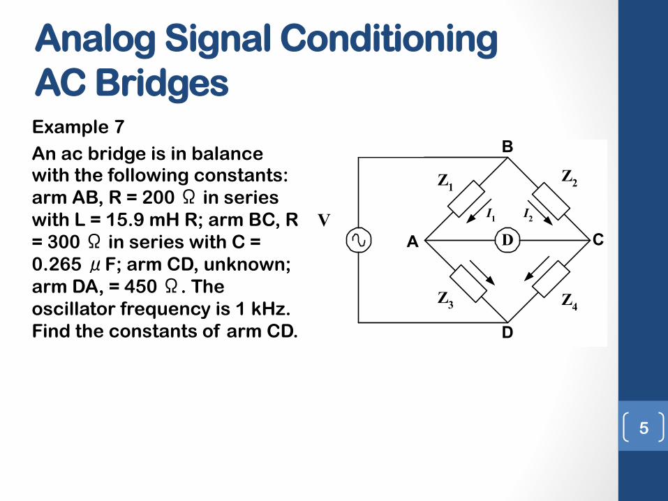
Analog Signal Conditioning AC Bridges Example 7 An ac bridge is in balance with the following constants: arm AB, R = 200 Ω in series with L = 15.9 mH R; arm BC, R = 300 Ω in series with C = 0.265 μF; arm CD, unknown; arm DA, = 450 Ω. The oscillator frequency is 1 kHz. Find the constants of arm CD.
5
Example an ac bridge is in balance with the following constants: arm AB, R = 200 :in series with L = 15.9 mH R; arm BC, R = 300 : in series with C = 0.265 PF; arm CD, unknown; arm DA, = 450 :. The oscillator frequency is 1 kHz. Find the constants of arm CD.
SOLUTION
The general equation for bridge balance states that
This result indicates that Z4 is a pure inductance with an inductive reactance of 150 :at at frequency of 1kHz. Since the inductive reactance XL = 2SfL, we solve for L and obtain L = 23.9 mH
D
Z1 Z2
Z4Z3
A C
D
B
I1 I2V 1
2
3
4
200 100 1/ 300 600 450
unknown
R j L jR j C jR
ZZ
� � : � � : :
ZZZZ
1 4 2 3Z Z = Z Z
1
450 (200 100) 150 (300 600)
j jj
u � :
�2 3
4Z ZZ =Z

Analog Signal Conditioning AC Bridges Capacitance Comparison Bridge
Comparison Bridge: Capacitance
Measure an unknown inductance or capacitance by comparing with it with a known inductance or capacitance.
Diagram of Capacitance Comparison Bridge
Unknown capacitance
At balance point: 3x1 2Z Z = Z Z
where1 1 2 2 3 3
3
1= ; ; and R R Rj CZ
�Z Z = Z
1 2 33
1 1x
x
R R R Rj C j CZ Z
§ · § ·� �¨ ¸ ¨ ¸
© ¹ © ¹
Separation of the real and imaginary terms yields: 2 3
1xR RRR
13
2x
RC CR
and
Frequency independentTo satisfy both balance conditions, the bridge must contain two variable elements in its configuration.
D
R2R1
RxC3
R3 Cx
Vs
6

Capacitance Comparison Bridge
Example 8 A similar angle bridge is used to measure a
capacitive impedance at a frequency of 2kHz. The bridge constant at balance are C3 =100µF R1=10k Ω
R2=50k Ω R3=100k Ω
Find the equivalent series circuit of the unknown impedance
7

Comparison Bridge: Inductance
Measure an unknown inductance or capacitance by comparing with it with a known inductance or capacitance.
Diagram of Inductance Comparison Bridge
Unknown inductance
At balance point: 3x1 2Z Z = Z Z
where1 1 2 2 3 3 3= ; ; and R R R j LZ �Z Z = Z
� � � �1 2x x S SR R j L R R j LZ Z� �
Separation of the real and imaginary terms yields: 2 3
1xR RRR
23
1x
RL LR
and
Frequency independentTo satisfy both balance conditions, the bridge must contain two variable elements in its configuration.
D
R2R1
L3
Rx
LxR3
Vs
8
Analog Signal Conditioning AC Bridges Inductance Comparison Bridge

Maxwell Bridge
Measure an unknown inductance in terms of a known capacitance
D
R2R1
C1
R3Rx
Lx
Diagram of Maxwell Bridge
V
Unknown inductance
At balance point: 3 1x 2Z = Z Z Y
where2 2 3 3 1 1
1
1; ; and =R R j CR
Z �Z = Z Y
2 3 11
1x x xR j L R R j C
RZ Z
§ ·� �¨ ¸
© ¹Z =
Separation of the real and imaginary terms yields: 2 3
1xR RRR
2 3 1xL R R C and
Frequency independentSuitable for Medium Q coil (1-10), impractical for high Q coil: since R1 will be very large. 9
Analog Signal Conditioning AC Bridges Maxwell Bridge
Hay Bridge
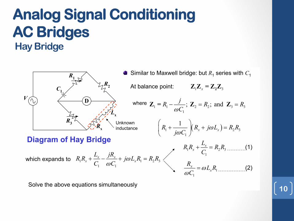
Similar to Maxwell bridge: but R1 series with C1
Diagram of Hay Bridge
V
At balance point: 1 3x 2Z Z = Z Z
where1 1 2 2 3 3
1
; ; and jR R RCZ
� Z = Z Z
� �1 2 31
1x xR R j L R R
j CZ
Z§ ·
� � ¨ ¸© ¹
which expands to
Unknown inductance
D
R2
R1
C1
R3 Rx
Lx
1 1 2 31 1
x xx xL jRR R j L R R RC C
ZZ
� � �
1 2 31
xxLR R R RC
�
11
xx
R L RC
ZZ
Solve the above equations simultaneously
(1)
(2)
10
Analog Signal Conditioning AC Bridges Hay Bridge
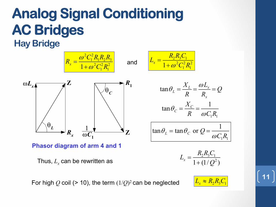
Hay Bridge: continues
2 3 12 2 2
1 11xR R CLC RZ
�
2 21 1 2 3
2 2 21 11x
C R R RRC R
ZZ
�
ZLx
Rx
Z
TL
R1
Z
TC
ZC1�
and
Phasor diagram of arm 4 and 1
tan xLL
x
LX QR R
ZT
1 1
1tan CC
XR C R
TZ
1 1
1tan tan or L C QC R
T TZ
Thus, Lx can be rewritten as2 3 1
21 (1/ )xR R CL
Q
�
For high Q coil (> 10), the term (1/Q)2 can be neglected 2 3 1xL R R C| 11
Analog Signal Conditioning AC Bridges Hay Bridge
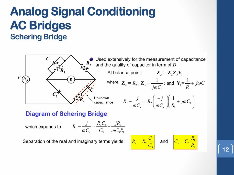
Schering Bridge
Used extensively for the measurement of capacitance and the quality of capacitor in term of D
D
R2R1
C1
C3Rx
Cx
V
Unknown capacitance
Diagram of Schering Bridge
At balance point: 3 1x 2Z = Z Z Y
where2 2 3 1
3 1
1 1; ; and =R j Cj C R
ZZ
�Z = Z Y
2 11
1x
x x
j jR R j CC C R
ZZ Z
§ ·§ ·�� �¨ ¸¨ ¸
© ¹© ¹
which expands to 2 1 2
3 3 1x
x
j R C jRRC C C RZ Z
� �
Separation of the real and imaginary terms yields: 12
3x
CR RC
13
2x
RC CR
and
12
Analog Signal Conditioning AC Bridges Schering Bridge

Schering Bridge: continues
Dissipation factor of a series RC circuit: xx x
x
RD R CX
Z
Dissipation factor tells us about the quality of a capacitor, how close the phase angle of the capacitor is to the ideal value of 90o
1 1x xD R C RCZ Z For Schering Bridge:
For Schering Bridge, R1 is a fixed value, the dial of C1 can be calibrated directly in Dat one particular frequency
13
Analog Signal Conditioning AC Bridges Schering Bridge
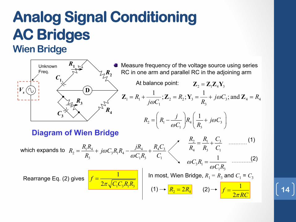
Wien Bridge
Measure frequency of the voltage source using series RC in one arm and parallel RC in the adjoining arm
D
R2
R1
C1
C3R4
R3
Vs
Diagram of Wien Bridge
At balance point:2 1 4 3 Z Z Z Y
2 1 4 31 3
1jR R R j CC R
ZZ
§ ·§ · � �¨ ¸¨ ¸© ¹ © ¹
Unknown Freq.
which expands to 4 31 4 42 3 1 4
3 1 3 1
R CR R jRR j C R RR C R C
ZZ
� � �
32 1
4 3 1
CR RR R C
�
3 11 3
1C RC R
ZZ
(1)
(2)
1 3 1 3
12
fC C R RS
Rearrange Eq. (2) gives In most, Wien Bridge, R1 = R3 and C1 = C3
2 42R R 12
fRCS
(1) (2)
4433
3221
11 and ;1;;1 RCjR
RCj
R � � ZYZZ ZZ
14
Analog Signal Conditioning AC Bridges Wien Bridge

Wagner Ground Connection
D
R2R1
C3 Rx
1
2
R3 Cx
Rw
Cw
C1 C2
D
A B
C
Diagram of Wagner ground
Wagner ground connection eliminates some effects of stray capacitances in a bridge circuitSimultaneous balance of both bridge makes the point 1 and 2 at the ground potential. (short C1and C2 to ground, C4 andC5 are eliminated from detector circuit) The capacitance across the bridge arms e.g. C6cannot be eliminated by Wagner ground.
Wagner ground
Stray across armCannot eliminate
One way to control stray capacitances is by Shielding the arms, reduce the effect of stray capacitances but cannot eliminate them completely.
C4
C5C6
15
Analog Signal Conditioning AC Bridges Wagner Ground