lecture 3 - fizipedia.bme.hu · broadband communication is very much possible over fiber optics...
TRANSCRIPT
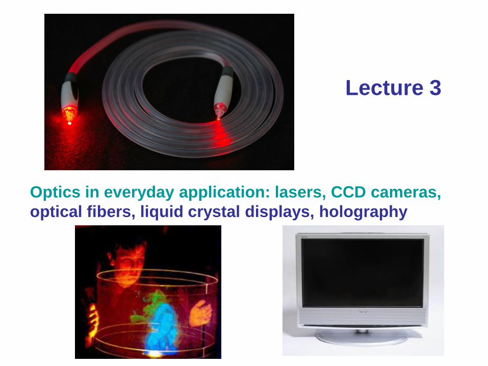
Optics in everyday application: lasers, CCD cameras,
optical fibers, liquid crystal displays, holography
Lecture 3

The gas laser
The He-Ne laser 1.
(helium-neon)
The mechanism producing population inversion
and light amplification in a He-Ne laser
plasma originates with inelastic collision of
energetic electrons with ground state helium
atoms in the gas mixture. As shown in the
accompanying energy level diagram, these
collisions excite helium atoms from the
ground state to higher energy
excited states, among them the 23S1 and
21S0 long-lived metastable states. Because
of a fortuitous near coincidence between the
energy levels of the two He metastable states,
and the 3s2 and 2s2 (levels of neon, collisions
between these helium metastable atoms and
ground state neon atoms results in a selective
and efficient transfer of excitation energy
from the helium to neon.

The He-Ne laser 2.
(helium-neon)
Gas lasers typically use a window tilted at Brewster's
angle to allow the beam to leave the laser tube.
Since the window reflects some s-polarized light but
no p-polarized light, the gain for the s polarization is
reduced, but that for the p polarization is not affected.
This causes the laser's output to be p polarized, and
allows lasing with no loss due to the window.
The physical mechanism for this can be qualitatively
understood from the manner in which electric
dipoles in the media respond to p-polarized light.
One can imagine that light incident on the surface is
absorbed, and then re-radiated by oscillating electric
dipoles at the interface between the two media. The
refracted light is emitted perpendicular to the direction
of the dipole moment; no energy can be radiated in
the direction of the dipole moment. That is, if the
oscillating dipoles are aligned along the supposed
direction of the reflection, no light is reflected at all. 1
2
n
ntg B
θr
90 Br

The He-Ne laser 3.
(helium-neon)Medical treatment
Cosmetic laser
treatment

The semiconductor laser
A laser diode is an electrically pumped semiconductor laser in which the active
medium is formed by a p-n junction of a semiconductor diode similar to that found
in a light-emitting diode. The laser diode is distinct from the optically pumped
semiconductor laser, in which, while also semiconductor based, the medium is
pumped by a light beam rather than electric current.
Light source in fiber-optic communication. High efficiency!

A semiconductor
laser application
CD (or DVD) reader & writer
(head)

The Lorentz-transformation
'' & )''(
2x
c
vttvtxx
x
c
vttvtxx
2' & )('
K → K’ : v → -v
2
2
c
v-1
1
xx’
yy’
KK’
v
The transformation describe how measurements
of space and time by two observers are related.
The Maxwell equations are invariant to Lorentz
transformation, that is a linear transformation.
The Maxwell equations are not invariant to
Galilean transformation (t=t’, x=x’+vt).
The Lorentz-transformation:
The speed of light is the same in K and K’: cc

The Doppler-effect 1.
The electromagnetic wave in K (traveling along the x axis):
The electromagnetic wave in K’ (traveling along the x’ axis):
x
λ
πft-Akx)t(EE(x,t)
22coscos 0
''
2''2cos
2vtx
λ
π-x
c
vtfAE(x,t)
c
f
1
'
1
11
2 '
1
1
2cos'
1
12
'
1
1
2cos
2
2
2
2x
c
vc
v
λπ-t
c
vc
v
fAx
c
v
c
v
λ
π-t
c
v
c
v
fAE(x,t)
c
vc
v
ff
1
1
'
c
vc
v
1
1
'
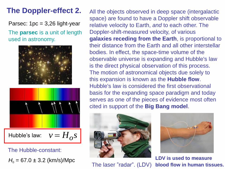
The Doppler-effect 2.
H0 = 67.0 ± 3.2 (km/s)/Mpc
Parsec: 1pc = 3,26 light-year
sHv o Hubble’s law:
All the objects observed in deep space (intergalactic
space) are found to have a Doppler shift observable
relative velocity to Earth, and to each other. The
Doppler-shift-measured velocity, of various
galaxies receding from the Earth, is proportional to
their distance from the Earth and all other interstellar
bodies. In effect, the space-time volume of the
observable universe is expanding and Hubble's law
is the direct physical observation of this process.
The motion of astronomical objects due solely to
this expansion is known as the Hubble flow.
Hubble's law is considered the first observational
basis for the expanding space paradigm and today
serves as one of the pieces of evidence most often
cited in support of the Big Bang model.
The laser ”radar”. (LDV)
The parsec is a unit of length
used in astronomy.
The Hubble-constant:
LDV is used to measure
blood flow in human tissues.

Optical activity
yx nn
Optical rotation (optical activity) is the
turning of the plane of linearly polarized light
about the direction of motion as the light
travels through certain materials. It occurs
in solutions of chiral molecules such as
sucrose (sugar), solids with rotated crystal
planes such as quartz. It is used in the sugar
industry to measure syrup concentration,
in optics to manipulate polarization, in
chemistry to characterize substances in
solution. It is being developed as a method
to measure blood sugar concentration in
diabetic people.
0
0
0
0
y
xkin
kin
y
x
E
E
e
e
E
E
oy
ox
ook
2phase
shift

Each pixel of an LCD typically consists of a layer of molecules
aligned between two transparent electrodes, and two polarizing
filters, the axes of transmission of which are (in most of the
cases) perpendicular to each other. Without the liquid crystal
between the polarizing filters, light passing through the first
filter would be blocked by the second (crossed) polarizer.
The liquid-crystal 1.

The liquid-crystal 2.
The twisted nematic effect is based on the precisely
controlled realignment of liquid crystal molecules
between different ordered molecular configurations
under the action of an applied electric field. This is
achieved with little power consumption and at low
operating voltages. temperature

The liquid-crystal 3.
The structure of LCD monitor
Wave-guide foil

Optical fibers 1.
Total internal reflection: the wave cannot pass
through and is entirely reflected. This can only
occur where the wave travels from a medium with
a higher refractive index (n1) to one with a lower
refractive index (n2). For example, it will occur
with light when passing from glass to air, but
not when passing from air to glass.
The critical angle:
2
1sinn
nc

Total internal reflection
Optical fibers 2.
laser
beam

Optical fibers 3.
Fiber with a core diameter less than about ten times the wavelength of the propagating
light cannot be modeled using geometric optics. Instead, it must be analyzed as an
electromagnetic structure, by solution of Maxwell's equations as reduced to the
electromagnetic wave equation. As an optical waveguide, the fiber supports one or
more confined transverse modes by which light can propagate along the fiber.
The waveguide analysis shows that the light energy in the fiber is not completely
confined in the core. Instead, especially in single-mode fibers, a significant fraction
of the energy in the bound mode travels in the cladding as an evanescent wave.
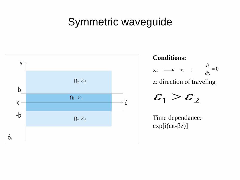
Symmetric waveguide
Conditions:
x: ∞ :
z: direction of traveling
Time dependance:
exp[i(ωt-βz)]
0
x
21

Maxwell eq.-s:
(j=1, 2)
zox
yox
xoyz
zjox
yjox
xjoyz
Hiy
E
HiEi
HiEiy
E
Eiy
H
EiHi
EiHiy
H
T.E.
T.M.
T.E. (5), (6) →(1) : 022
2
2
xjo
x Eky
E oook
Traveling modes: 122
22 oo kk
New variables:2
2222
21
221
o
o
k
kk
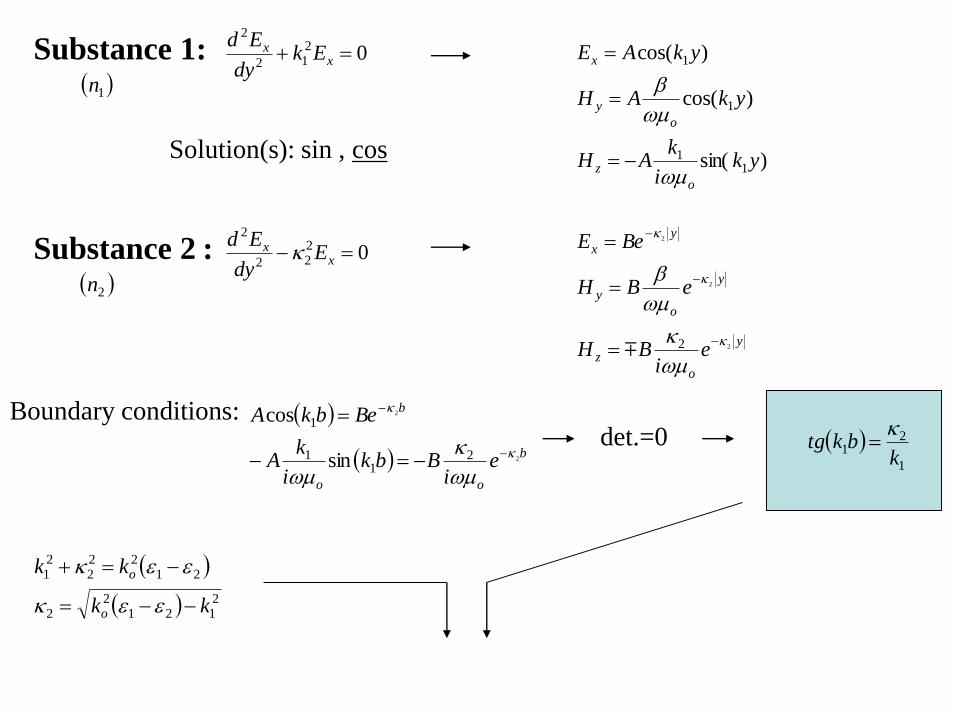
Substance 1: 1n
0212
2
xx Ek
dy
Ed
Solution(s): sin , cos )sin(
)cos(
)cos(
11
1
1
yki
kAH
ykAH
ykAE
o
z
o
y
x
Substance 2 : 0222
2
xx E
dy
Ed
y
o
z
y
o
y
y
x
ei
BH
eBH
BeE
2
2
2
2
Boundary conditions:
b
oo
b
ei
Bbki
kA
BebkA
2
2
21
1
1
sin
cos
det.=0
1
21
kbktg
2n
2121
22
2122
22
1
kk
kk
o
o

2121
211 kkbktgk o
21
2
1
obkV
bw
bku
Intr.:
222
22)(
Vwu
uVuutg
u
w
2 V 2
0k
1n
2n

Optical fibers 4.
Connectors of
multimode fibres
The structure of a typical
single-mode fiber.
1. Core: 8 µm diameter
2. Cladding: 125 µm dia.
3. Buffer: 250 µm dia.
4. Jacket: 400 µm dia.
Optical cable
Intensity distribution
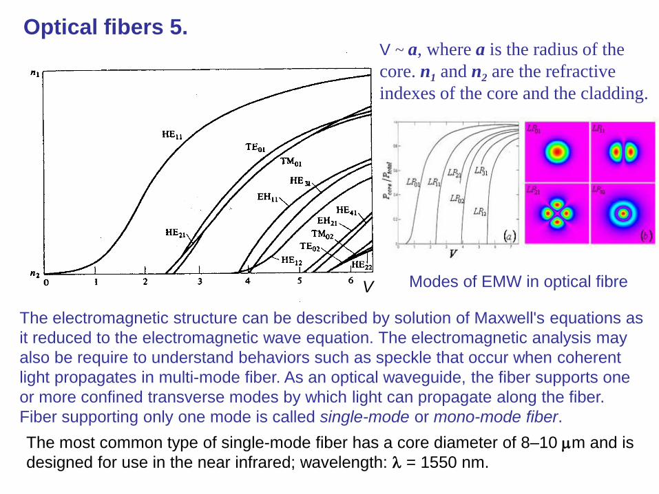
Optical fibers 5.
V
V ~ a, where a is the radius of the
core. n1 and n2 are the refractive
indexes of the core and the cladding.
The electromagnetic structure can be described by solution of Maxwell's equations as
it reduced to the electromagnetic wave equation. The electromagnetic analysis may
also be require to understand behaviors such as speckle that occur when coherent
light propagates in multi-mode fiber. As an optical waveguide, the fiber supports one
or more confined transverse modes by which light can propagate along the fiber.
Fiber supporting only one mode is called single-mode or mono-mode fiber.
The most common type of single-mode fiber has a core diameter of 8–10 m and is
designed for use in the near infrared; wavelength: = 1550 nm.
Modes of EMW in optical fibre

Op
tical fib
ers
6.
The advantages of optical fiber communication with respect to copper wire systems are:-
1. Broad Bandwidth
Broadband communication is very much possible over fiber optics which means that
audio signal, video signal, microwave signal, text and data from computers can be
modulated over light carrier wave and demodulated by optical receiver at the other end.
It is possible to transmit around 3,000,000 full-duplex voice or 90,000 TV channels over
one optical fiber.
2. Immunity to Electromagnetic Interference
Optical fiber cables carry the information over light waves which travel in the fibers
due to the properties of the fiber materials, similar to the light traveling in free space.
The light waves (EMW) are unaffected by other electromagnetic radiation nearby.
The optical fiber is electrically non-conductive, so it does not act as an antenna to
pick up electromagnetic signals which may be present nearby. So the information
traveling inside the optical fiber cables is immune to electromagnetic interference e.g.
radio transmitters, power cables adjacent to the fiber cables, or even electromagnetic
pulses generated by nuclear devices.
3. Low attenuation loss over long distances
There are various optical windows in the optical fiber cable at which the attenuation
loss is found to be comparatively low and so transmitter and receiver devices are
developed and used in these low attenuation region. Due to low attenuation of 0.2dB/km
in optical fiber cables, it is possible to achieve long distance communication efficiently
over information capacity rate of 1 Tbit/s.
4 Electrical Insulator
Optical fibers are made and drawn from silica glass which is nonconductor of electricity
and so there are no ground loops and leakage of any type of current. Optical fibers are
thus laid down along with high voltage cables on the electricity poles due to its electrical
insulator behavior.

Optical fibers 7.
The Nobel Prize in Physics 2009
Charles Kuen Kao Willard S. Boyle George E. Smith
The Nobel Prize in Physics 2009 was divided, one half awarded to Charles Kuen Kao
"for groundbreaking achievements concerning the transmission of light in fibers for
optical communication", the other half jointly to Willard S. Boyle and George E. Smith
"for the invention of an imaging semiconductor circuit - the CCD sensor".

Photography
y)I(x,thy)h(x, o
The transmission of the photoplate (or film):
iof
111
Linear range
A light-sensitive emulsion
of silver salts is applied to
a glass plate (or film).

Holography 1.
1st step: Exposition*or
*roro EEEEIII
Interference pattern (on holoplate):
Holography: lensless photography
2nd step: developement
(chemical process)
y)I(x,thy)h(x, o
The transmission of the hologram:
Ref: reference beam
(plane wave of spherical wave)
Obj: object wave
(reflected from the 3D object)
Hologram:
the recorded
interference
pattern
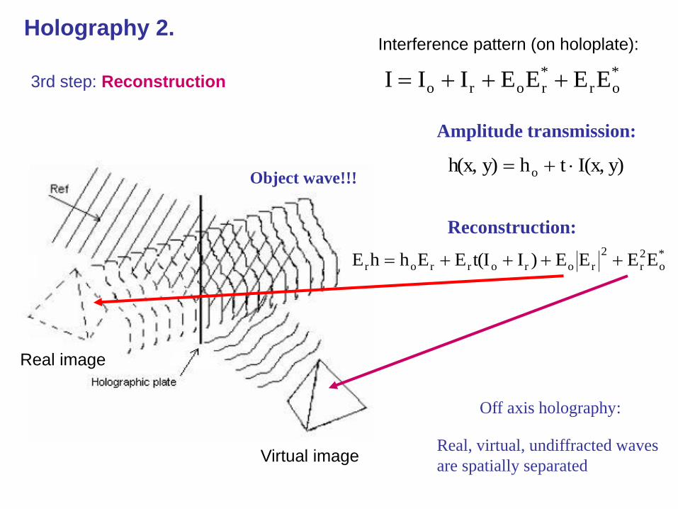
Holography 2.
Object wave!!!y)I(x,thy)h(x, o
Amplitude transmission:
Reconstruction:
*o
2r
2
rororror EEEE)It(IEEhhE
Off axis holography:
Real, virtual, undiffracted waves
are spatially separated
*or
*roro EEEEIII
Interference pattern (on holoplate):
3rd step: Reconstruction
Real image
Virtual image

+ =
CameraChip
type
Number of
pixels
Pixel size
[m2]
Frames per
second
Dynamic
range
max for
=633nm
Roper Sci.
MegaPlus 1.4iFT
1017*
10356.8 * 6.8 6.9 8 bit 2.7°
Roper Sci.
Megaplus 16.8iFT
4096*
40969 * 9 0.47 8 bit 2.0°
Roper Sci.
Megaplus ES 1.0IT
1008*
10189 * 9 30 8 or 10 bit 2.0°
Roper Sci.
Megaplus 4.0IT
2048*
20487.4 * 7.4 30 8 or 12 bit 2.45°
Hamamatsu
C8484-01PSI
1344*
10246.45 * 6.45 8.3 12 bit 2.81°
Duncan
DT1100PS
1392*
10404.65 * 4.65 12 8 or 12 bit 3.9°
FT: full frame: interline transfer, PSI: progressive scan interline, PS: progressive scan
The resolution of a holographic plate: 5000 lines/mm
Holography 3. Digital holography 1.
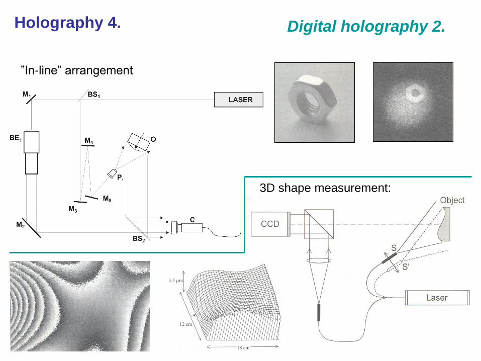
”In-line” arrangement
Digital holography 2.
3D shape measurement:
Holography 4.

Digital holography 3.Holography 5.
Gábor Dénes (Dennis Gabor): a Hungarian electrical engineer and
physicist, he invented the holography.
He received the 1971 Nobel Prize in Physics.

Digital holography 4.Holography 6.
A computer-generated hologram:

Holography 7.
X-ray, neutron, electron holography
Source: an atom
Source: atom
Reference wave: primary wave
(the original wave)
Object wave: secondary waves
scattered from the neighbor atomsComputer generated reconstruction