lecture 20: light, reflectance and photometric stereo cs6670: computer vision noah snavely
Post on 22-Dec-2015
227 views
TRANSCRIPT

Lecture 20: Light, reflectance and photometric stereo
CS6670: Computer VisionNoah Snavely

Light
by Ted Adelson
• Readings– Szeliski, 2.2, 2.3.2

Light
by Ted Adelson
• Readings– Szeliski, 2.2, 2.3.2

Properties of lightToday
• What is light?• How do we measure it?• How does light propagate?• How does light interact with matter?

RadiometryWhat determines the brightness of an image pixel?
Light source propertiesLight source properties
Surface properties
Surface properties
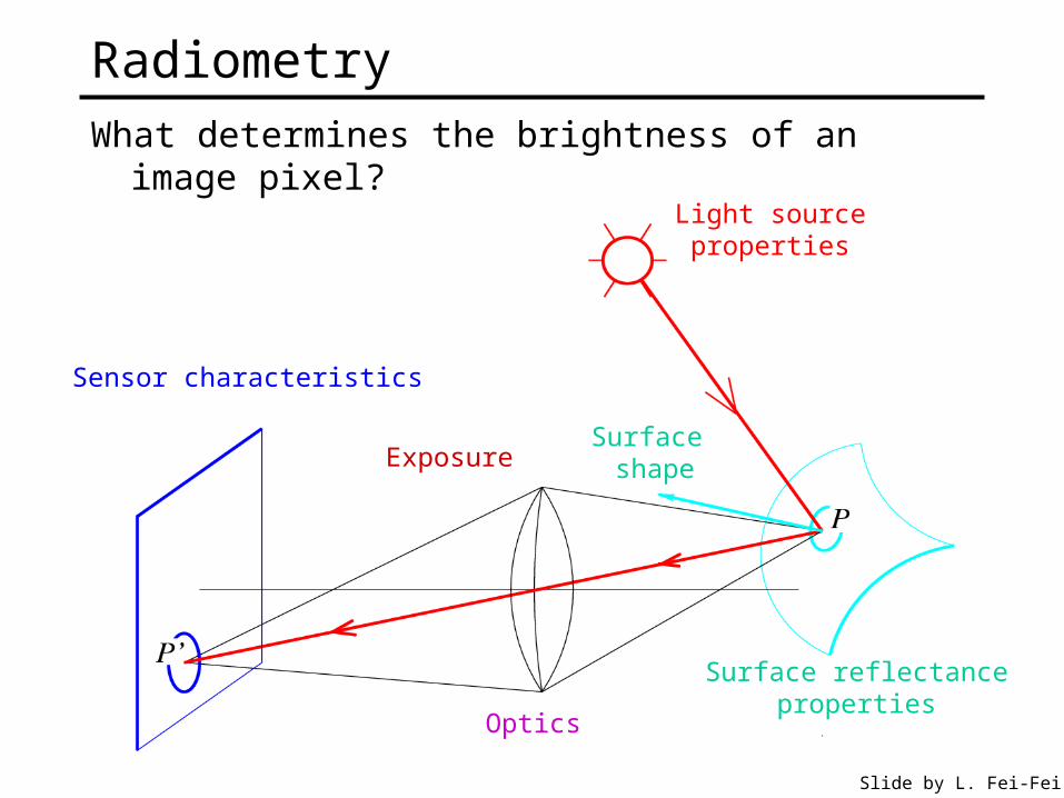
RadiometryWhat determines the brightness of an image pixel?
Light sourceproperties
Surface shape
Surface reflectanceproperties
Optics
Sensor characteristics
Slide by L. Fei-Fei
Exposure

What is light?Electromagnetic radiation (EMR) moving along rays in space
• R() is EMR, measured in units of power (watts)– is wavelength
Light field• We can describe all of the light in the scene by specifying the
radiation (or “radiance” along all light rays) arriving at every point in space and from every direction

What is light?Electromagnetic radiation (EMR) moving along rays in space
• R() is EMR, measured in units of power (watts)– is wavelength
Perceiving light• How do we convert radiation into “color”?• What part of the spectrum do we see?

Visible lightWe “see” electromagnetic
radiation in a range of wavelengths

Light spectrumThe appearance of light depends on its power spectrum
• How much power (or energy) at each wavelength
daylight tungsten bulb
Our visual system converts a light spectrum into “color”• This is a rather complex transformation
fluorescent light

The human visual system
Color perception• Light hits the retina, which contains photosensitive cells
– rods and cones
• These cells convert the spectrum into a few discrete values

Density of rods and cones
Rods and cones are non-uniformly distributed on the retina• Rods responsible for intensity, cones responsible for color• Fovea - Small region (1 or 2°) at the center of the visual field containing the
highest density of cones (and no rods).• Less visual acuity in the periphery—many rods wired to the same neuron

Demonstrations of visual acuity
With one eye shut, at the right distance, all of these letters should appear equally legible (Glassner, 1.7).
Light response is nonlinearOur visual system has a large dynamic range
• We can resolve both light and dark things at the same time• One mechanism for achieving this is that we sense light
intensity on a logarithmic scale– an exponential intensity ramp will be seen as a linear ramp
• Another mechanism is adaptation– rods and cones adapt to be more sensitive in low light, less
sensitive in bright light.

Visual dynamic range

Color perception
Three types of cones• Each is sensitive in a different region of the spectrum
– but regions overlap– Short (S) corresponds to blue– Medium (M) corresponds to green– Long (L) corresponds to red
• Different sensitivities: we are more sensitive to green than red
• Colorblindness—deficiency in at least one type of cone
L response curve

Color perception
Rods and cones act as filters on the spectrum• To get the output of a filter, multiply its response curve by the
spectrum, integrate over all wavelengths– Each cone yields one number
• Q: How can we represent an entire spectrum with 3 numbers?
S
M L
Wavelength
Power
• A: We can’t! Most of the information is lost.– As a result, two different spectra may appear indistinguishable
» such spectra are known as metamers» http://www.cs.brown.edu/exploratories/freeSoftware/repository/edu/brown/cs/expl
oratories/applets/spectrum/metamers_guide.html
Perception summary
The mapping from radiance to perceived color is quite complex!• We throw away most of the data• We apply a logarithm• Brightness affected by pupil size• Brightness contrast and constancy effects• Afterimages
The same is true for cameras• But we have tools to correct for these effects
– Coming soon: Computational Photography lecture

Light transport

Light sourcesBasic types
• point source• directional source
– a point source that is infinitely far away
• area source– a union of point sources
More generally• a light field can describe *any* distribution of light sources
What happens when light hits an object?

Reflectance spectrum (albedo)To a first approximation, surfaces absorb some
wavelengths of light and reflect others
These spectra are multiplied by the spectra of the incoming light, then by the spectra of the sensors

Material Properties

What happens when a light ray hits an object?
Some of the light gets absorbed• converted to other forms of energy (e.g., heat)
Some gets transmitted through the object• possibly bent, through “refraction”• a transmitted ray could possible bounce back
Some gets reflected• as we saw before, it could be reflected in multiple directions
(possibly all directions) at once
Let’s consider the case of reflection in detail

Classic reflection behavior
ideal specular
Lambertianrough specular
from Steve Marschner

The BRDFThe Bidirectional Reflection Distribution Function
• Given an incoming ray and outgoing raywhat proportion of the incoming light is reflected along outgoing ray?
Answer given by the BRDF:
surface normal
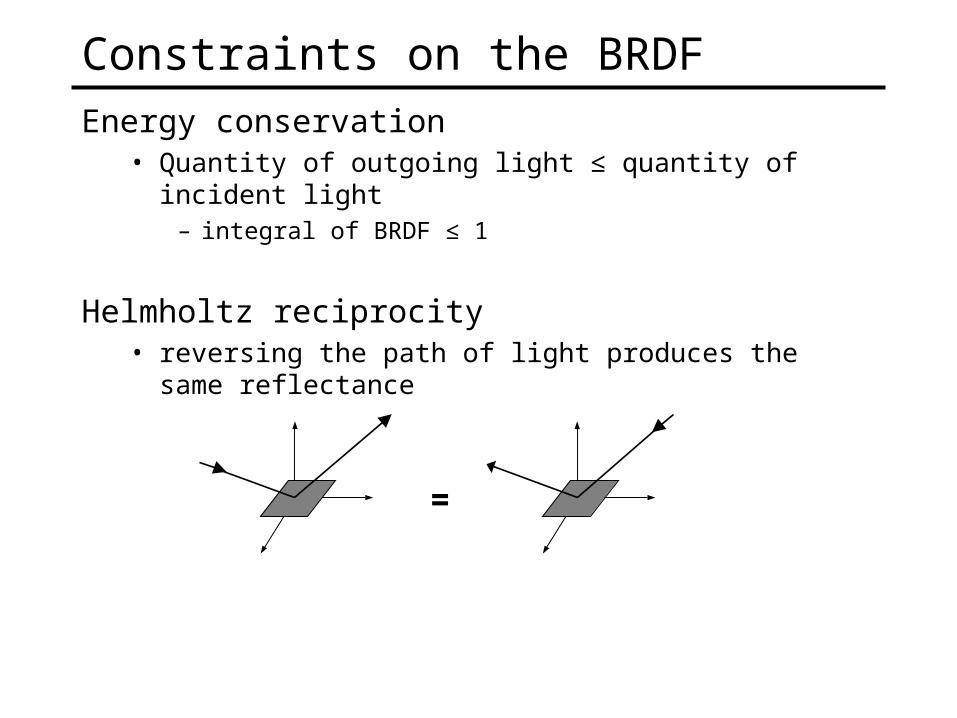
Constraints on the BRDFEnergy conservation
• Quantity of outgoing light ≤ quantity of incident light– integral of BRDF ≤ 1
Helmholtz reciprocity• reversing the path of light produces the same reflectance
=

BRDF’s can be incredibly complicated…
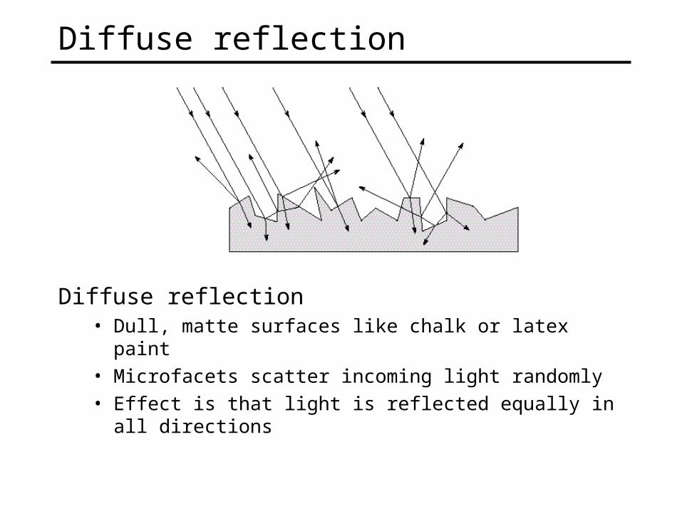
Diffuse reflection
Diffuse reflection• Dull, matte surfaces like chalk or latex paint• Microfacets scatter incoming light randomly• Effect is that light is reflected equally in all directions
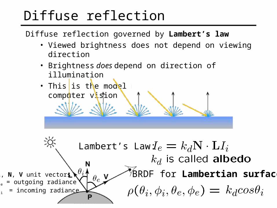
Diffuse reflection governed by Lambert’s law• Viewed brightness does not depend on viewing direction• Brightness does depend on direction of illumination• This is the model most often used in computer vision
Diffuse reflection
L, N, V unit vectorsIe = outgoing radianceIi = incoming radiance
Lambert’s Law:
BRDF for Lambertian surface

BRDF modelsPhenomenological
• Phong [75]• Ward [92]• Lafortune et al. [97]• Ashikhmin et al. [00]
Physical• Cook-Torrance [81]• Dichromatic [Shafer 85]• He et al. [91]
Here we’re listing only some well-known examples

Measuring the BRDF
Gonioreflectometer• Device for capturing the BRDF by moving a camera + light source
• Need careful control of illumination, environment
traditional design by Greg Ward

Questions?• 3-minute break
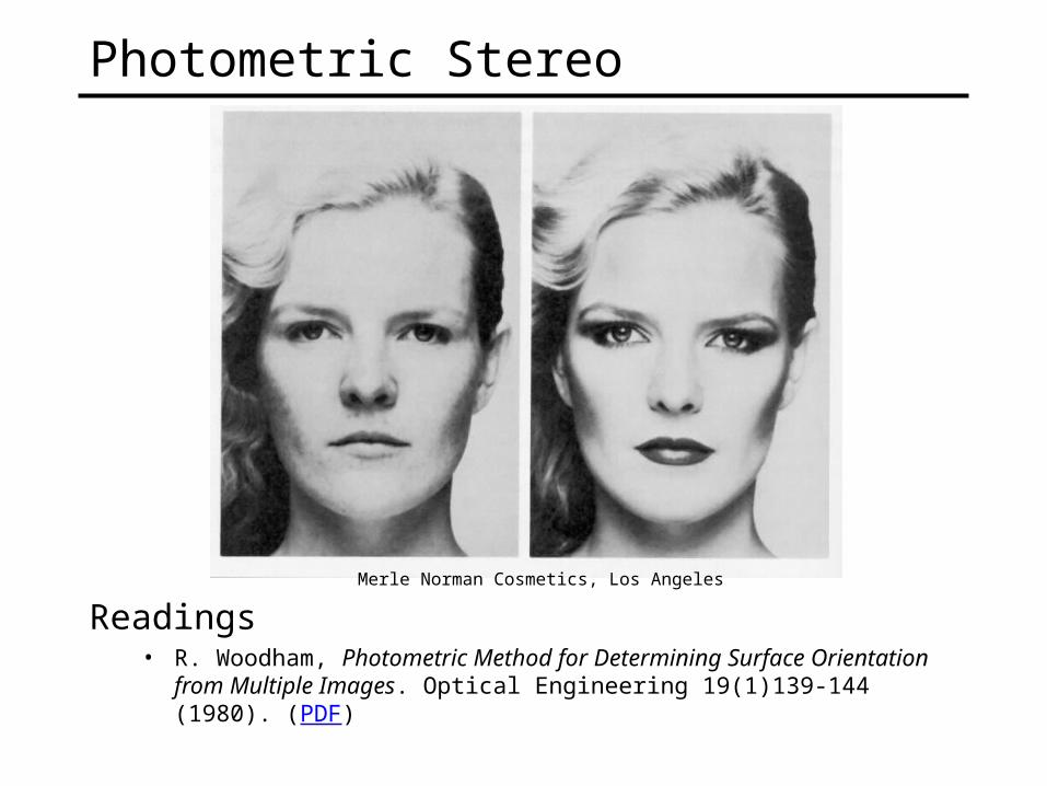
Photometric Stereo
Readings• R. Woodham, Photometric Method for Determining Surface Orientation from
Multiple Images. Optical Engineering 19(1)139-144 (1980). (PDF)
Merle Norman Cosmetics, Los Angeles
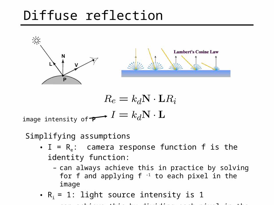
Diffuse reflection
Simplifying assumptions
• I = Re: camera response function f is the identity function:
– can always achieve this in practice by solving for f and applying f -1 to each pixel in the image
• Ri = 1: light source intensity is 1
– can achieve this by dividing each pixel in the image by Ri
image intensity of P

Shape from shading
Suppose
You can directly measure angle between normal and light source• Not quite enough information to compute surface shape• But can be if you add some additional info, for example
– assume a few of the normals are known (e.g., along silhouette)
– constraints on neighboring normals—“integrability”
– smoothness
• Hard to get it to work well in practice– plus, how many real objects have constant albedo?

Photometric stereo
N
L1
L2
V
L3
Can write this as a matrix equation:
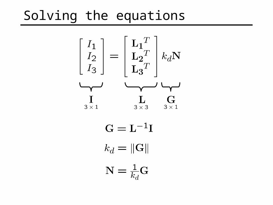
Solving the equations

More than three lightsGet better results by using more lights
What’s the size of LTL?
Least squares solution:
Solve for N, kd as before

Example
Recovered albedo Recovered normal field
Forsyth & Ponce, Sec. 5.4

Computing light source directionsTrick: place a chrome sphere in the scene
• the location of the highlight tells you where the light source is