lecture 12: piezoelectric sensors & actuators - …mech466/mech466-lecture-12.pdf · given the...
TRANSCRIPT

1
MECH 466Microelectromechanical Systems
University of VictoriaDept. of Mechanical Engineering
Lecture 12:Piezoelectric Sensors & Actuators
© N. Dechev, University of Victoria
2
Examples of piezoelectric sensors and actuators making use of cantilever beams
Example of piezoelectric sensors and actuators making use of a thin plate
Case Studies:
• Membrane Accelerometer
• Hard Drive Scanning Head Correction
Future Applications of Piezoelectric Sensors:
• The Daintiest Dynamos
Overview
© N. Dechev, University of Victoria

Given the following actuator:
Q: Find the vertical displacement (direction 3) at the end of the beam, when voltage V is applied across the piezoelectric material, via the electrodes.
3
Example #3: Piezoelectric Actuator
© N. Dechev, University of Victoria
3 2
1
Silicon beam
Piezoelectric layer
electrode layers
w
t(piezo)
L
LA
LB
tb
V
Note: Only the portion of the beam ‘LA’ will be bent due to the piezoelectric strip.
This is a case of the ‘inverse effect’, therefore:
Since there are no applied forces, this reduces to:
4© N. Dechev, University of Victoria
Example #3: Piezoelectric Actuator

Under the applied voltage, V:
Note: this equation can be re-written indicating the directions as:
(In other words, the electric field along direction 3, will cause strain along direction 1.)
5© N. Dechev, University of Victoria
Example #3: Piezoelectric Actuator
The equation for the strain due to the ‘inverse effect’ can be written in matrix format as:
In the case of this example, we know that:
6© N. Dechev, University of Victoria
Example #3: Piezoelectric Actuator

Additionally, we know that for typical piezoelectric materials, many values of the peizoelectric coefficient matrix are zero. For example, for ZnO, the matrix is:
Therefore, given the applied electric fields, and assuming the use of ZnO, the equation for strain due to the ‘inverse effect’ is:
7© N. Dechev, University of Victoria
Example #3: Piezoelectric Actuator
Due to the applied voltage V, the piezoelectric element will expand (strain) in direction 1. Since it is firmly attached to the beam, this expansion (strain) will cause segment LA to be curved into an arc with a radius r, as defined by:
where s(long) is the longitudinal strain = s1 in this example
8© N. Dechev, University of Victoria
Example #3: Piezoelectric Actuator

Therefore, since only segment LA of the beam will be bent, we can define the displacement (along direction 3) at the end of segment LA as:
where:
Therefore:
9© N. Dechev, University of Victoria
Example #3: Piezoelectric Actuator
3
1
rφ
δ(x=LA)
Since the rest of the beam does not bend, the tip deflection of the entire beam can be defined as:
10© N. Dechev, University of Victoria
Example #3: Piezoelectric Actuator
3
1
r
φ
δ(x=LA)
δ(beam)
Straight Portion of beam

Given the same actuator as in Example #3:
Q: Find the tip deflection given the following values:
11© N. Dechev, University of Victoria
Example #4: Piezoelectric Actuator
3 2
1
Silicon beam
Piezo = ZnO (see table 7.2 for properties)Beam = polysilicon (see past notes for properties)Vapplied = 100 Vtpiezo = 10 umtbeam = 5 umLA = 100 umL = 400 umwbeam = wpiezo = 30 um
V
w
t(piezo)
LLA LB
tb
12© N. Dechev, University of Victoria
Example #4: Piezoelectric Actuator
See Class Notes

13© N. Dechev, University of Victoria
Case Study 7.2: Membrane Piezoelectric Accelerometer
A membrane based accelerometer is made using the piezoelectric effect, using the following design:
Figure 7.6. Piezoelectric Accelerometer [Chang Liu]
Top Electrodes
Bottom Electrode
Cross-SectionA-A’
14© N. Dechev, University of Victoria
Case Study: Hard Drive R/W Head Correction
Disc drives store information on the surface of a ‘hard platter’ using magnetic ‘read/write heads’ to create magnetic ‘bits’ of info.
As the density (# of bits/unit area on the surface) of hard drives increased over the past two decades, mechanical factors such as ball bearings, manufacturing errors and inertial effects have created bottlenecks on the possible read/write speeds and data density.
Inside of a typical hard drive, with platter, voice coil, and scan arm visible.[How Stuff Works.com]
Multi-platters and Multi-scan heads visible.[How Stuff Works.com]

15© N. Dechev, University of Victoria
Case Study: Hard Drive R/W Head Correction
To overcome these problems, recent hard drives incorporate a ‘self-correction system, using piezoelectric (or other) microactuators, to keep the read/write head centered on the ‘data track’.
Illustration of hard drive internals.[IBM-Almaden-Research-Center]
Movie of hard drive operation,without and with ‘error correction’ from a microactuator[IBM-Almaden-Research-Center]
16© N. Dechev, University of Victoria
Case Study: Hard Drive R/W Head Correction
SEM (scanning electron microscope) image of a typical hard drive head, with microactuator.
SEM image of hard drive head (upside down)[IBM-Almaden-Research-Center]
17© N. Dechev, University of Victoria
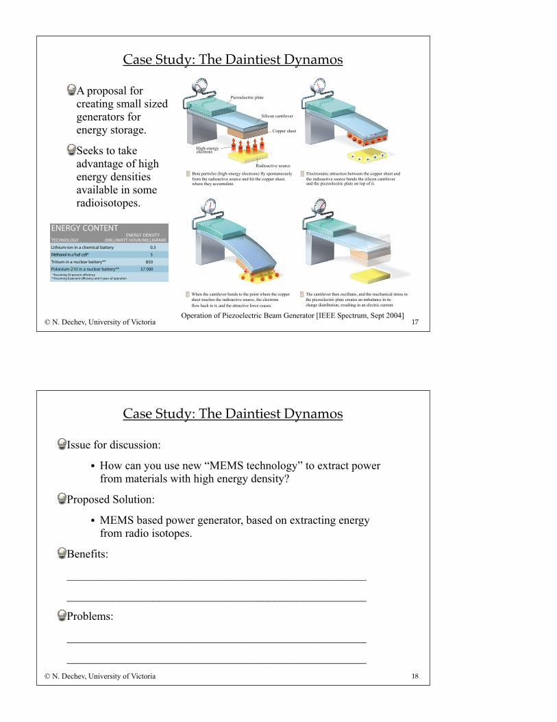
Case Study: The Daintiest Dynamos
A proposal for creating small sized generators for energy storage.
Seeks to take advantage of high energy densities available in some radioisotopes.
Operation of Piezoelectric Beam Generator [IEEE Spectrum, Sept 2004]
Beta particles (high-energy electrons) fly spontaneously
from the radioactive source and hit the copper sheet,
where they accumulate.
Electrostatic attraction between the copper sheet and
the radioactive source bends the silicon cantilever
and the piezoelectric plate on top of it.
1 2
Piezoelectric plate
Silicon cantilever
Copper sheet
High-energyelectrons
Radioactive source
When the cantilever bends to the point where the copper
sheet touches the radioactive source, the electrons
flow back to it, and the attractive force ceases.
The cantilever then oscillates, and the mechanical stress in
the piezoelectric plate creates an imbalance in its
charge distribution, resulting in an electric current.
3 4
ENERGY CONTENTENERGY DENSITY
TECHNOLOGY (MILLIWATT-HOUR/MILLIGRAM)
Lithium-ion in a chemical battery 0.3
3
85057 000
*llec leuf a ni lonahteM
Tritium in a nuclear battery**
Polonium-210 in a nuclear battery** *Assuming 50 percent e!ciency
**Assuming 8 percent e!ciency and 4 years of operation
18© N. Dechev, University of Victoria
Case Study: The Daintiest Dynamos
Issue for discussion:
• How can you use new “MEMS technology” to extract power from materials with high energy density?
Proposed Solution:
• MEMS based power generator, based on extracting energy from radio isotopes.
Benefits:
____________________________________________________
____________________________________________________
Problems:
____________________________________________________
____________________________________________________