lecture 11: reflection
TRANSCRIPT
LIGHT
REFRACTION , REFLECTION, GEOMETRIC OPTICS and PHOTOELECTRIC EFFECT
LIGHT.Light is a form of energy which travels in a vacuum at a speed of 3 x 10⁸ m.s-1 Light can exhibit properties of both waves and particles (photons). This property is referred to as wave–particle duality. The study of light, known as optics, is an important area in physics.Substances which allow light to pass through them are called transparent materials and substances which prevent light passing through are called opaque.
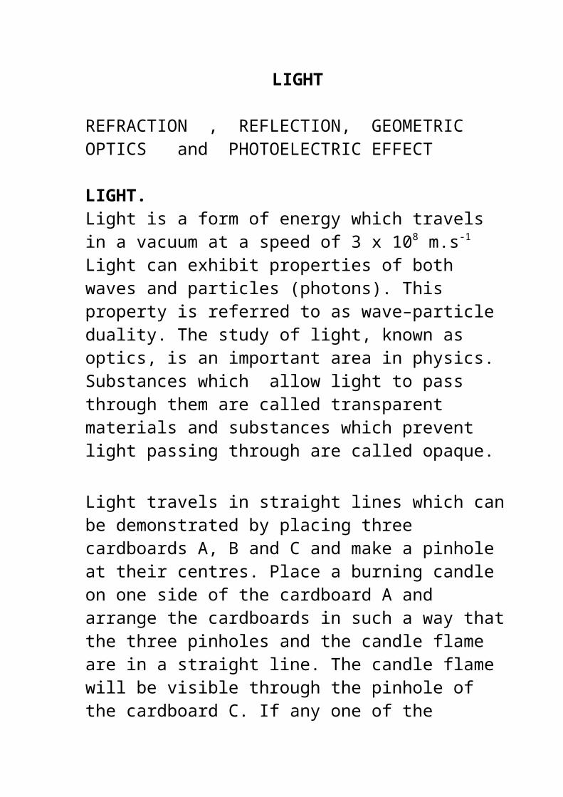
Light travels in straight lines which can be demonstrated by placing three cardboards A, B and C and make a pinhole at their centres. Place a burning candle on one side of the cardboard A and arrange the cardboards in such a way that the three pinholes and the candle flame are in a straight line. The candle flame will be visible through the pinhole of the cardboard C. If any one of the cardboards is slightly displaced the flame will not be visible. From this it is clear that light travels in a straight line.
The light can be seen by the observer at O if and only if A, B and C are in a straight line.
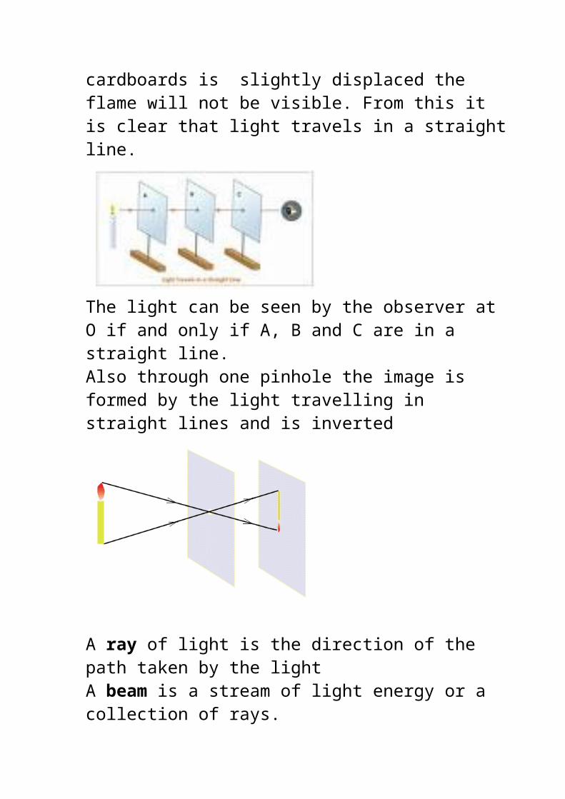
Also through one pinhole the image is formed by the light travelling in straight lines and is inverted
A ray of light is the direction of the path taken by the light A beam is a stream of light energy or a collection of rays.
A beam can be1. Parallel
A collection of parallel rays
2. Diverging
A collection of rays diverging from a point.
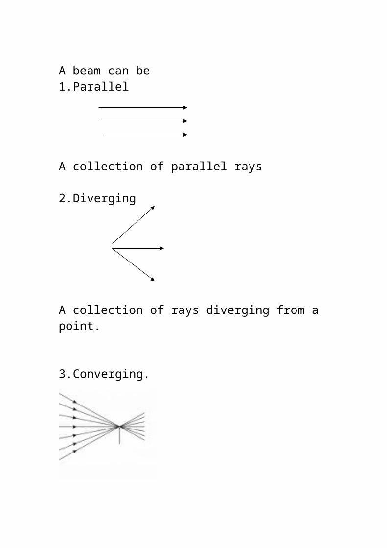
3. Converging.
A collection of rays converging to a point.
REFLECTION OF LIGHT.
When light falls on a smooth highly polished surface it is reflected i.e turned back. A piece of polished metal makes a good reflector.
LAWS OF REFLECTION.
LAW 1. The incident ray, the reflected ray and the normal all lie in the same plane.
Normal is the direction at 90o to the direction of the surface at the point.
LAW 2. The angle of incidence equals the angle of reflection. Both angles measured relative to the normal.
Example : Plane Mirror. Glass mirrors have a thin layer of silvering deposited on the back of the glass which is protected. An IMAGE is produced in the mirror. The term image is used for any reproduction of an object by means of rays of light.
The image in a plane mirror is always
1 Same size as the object and the same way up
2. As far behind the mirror as the object is in front.
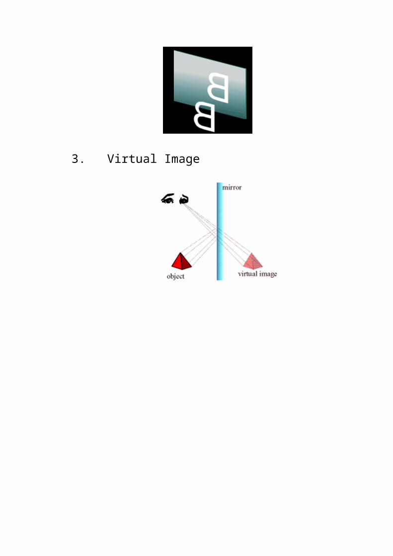
3. Turned sideways or laterally inverted
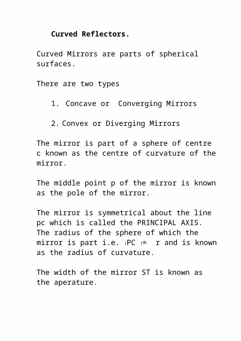
4. In the case of plane mirrors, the image is said to be a virtual image. Virtual images are images which are formed in locations where light does not actually reach. Light does not actually pass through the location on the other side of the mirror; it only appears to an observer as though the light is coming from this location.
Note an alternative description is that A real image can be focused on a screen, whereas a virtual image can not.
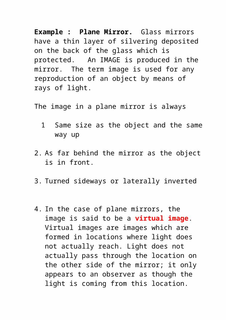
The angle of incidence i is the angle between the incident ray and the normal.
The reflected ray r is the angle between the reflected ray and the normal.
The angle of incidence i is equal to the angle or reflection r
Locating an Image in a plane mirror
Take a point object O the image is also a point ITo identify one particular point you need two lines. Therefore to locate a point we will use the intersection of two reflected rays. From the point O produce two incident rays. Each incident ray has a reflected ray
The intersection of the reflected rays indicates the location of the image.
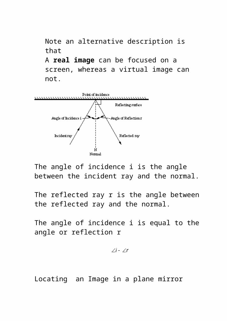
In the case of the plane mirror we notice that the reflected beam produced is a diverging beam and that the rays APPEAR to be diverging from a point behind the mirror.
The distance from M to O = the distance from M to IThe reflected rays form a diverging beam which APPEAR to come from I
In a plane mirror we can see that
1. Image is same size as the object the same way up and the same distance behind the mirror as the image is in front
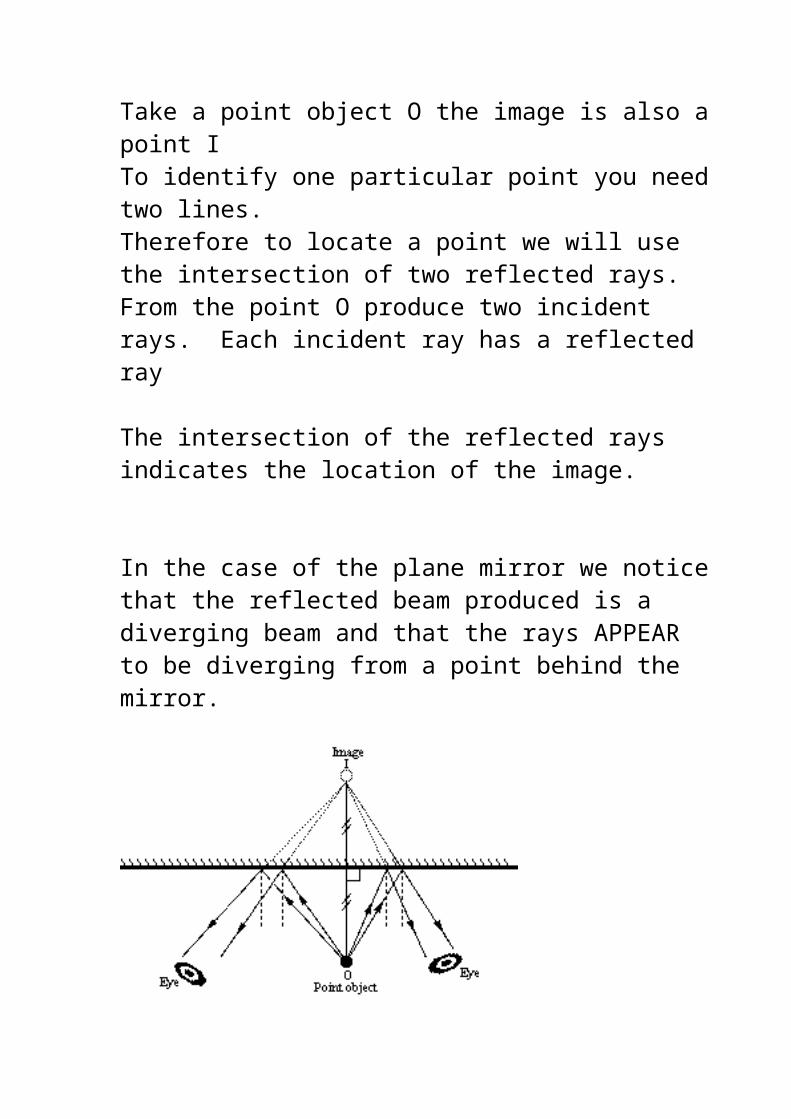
2. Laterally inverted
3. Virtual Image
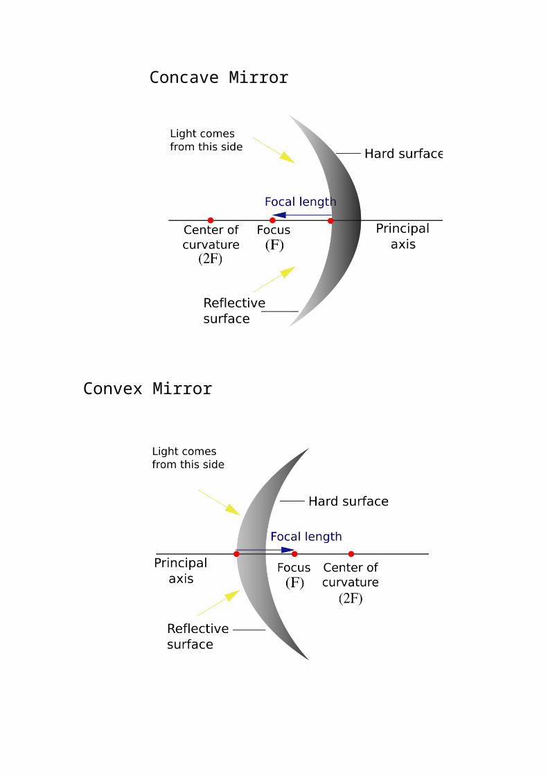
Curved Reflectors.
Curved Mirrors are parts of spherical surfaces.
There are two types
1. Concave or Converging Mirrors
2. Convex or Diverging Mirrors
The mirror is part of a sphere of centre c known as the centre of curvature of the mirror.
The middle point p of the mirror is known as the pole of the mirror.
The mirror is symmetrical about the line pc which is called the PRINCIPAL AXIS. The radius of the sphere of which the mirror is part i.e. PC = r and is known as the radius of curvature.
The width of the mirror ST is known as the aperature.
Concave Mirror
Convex Mirror
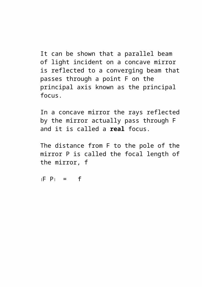
It can be shown that a parallel beam of light incident on a concave mirror is reflected to a converging beam that passes through a point F on the principal axis known as the principal focus.
In a concave mirror the rays reflected by the mirror actually pass through F and it is called a real focus.
The distance from F to the pole of the mirror P is called the focal length of the mirror, f
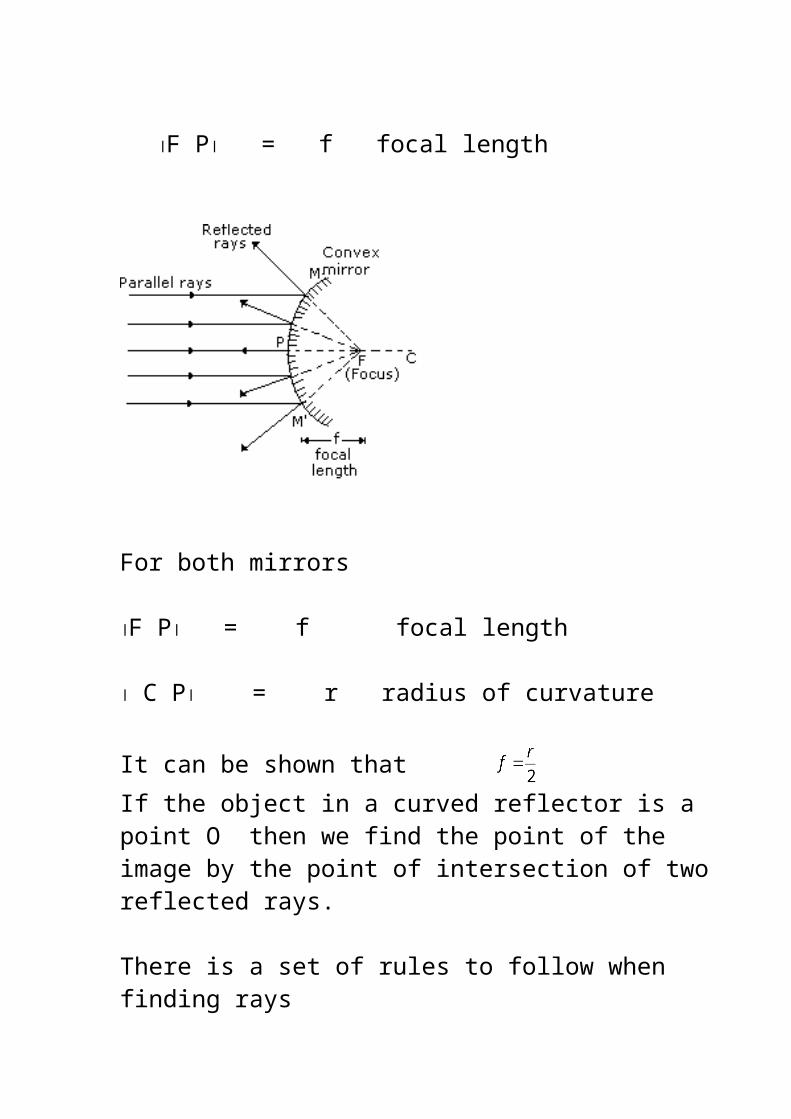
F P = f
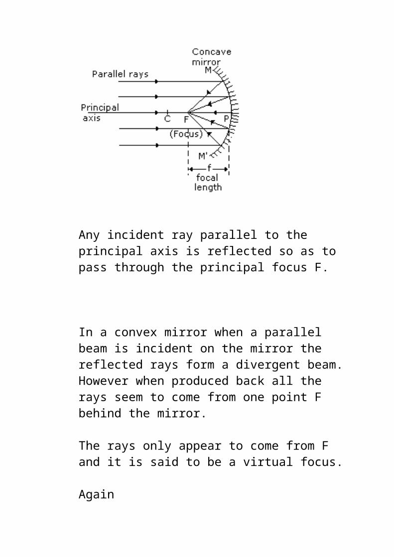
Any incident ray parallel to the principal axis is reflected so as to pass through the principal focus F.
In a convex mirror when a parallel beam is incident on the mirror the reflected rays form a divergent beam.
However when produced back all the rays seem to come from one point F behind the mirror.
The rays only appear to come from F and it is said to be a virtual focus.
Again
F P = f focal length
For both mirrors
F P = f focal length
C P = r radius of curvature
It can be shown that If the object in a curved reflector is a point O then we find the point of the image by the point of intersection of two reflected rays.
There is a set of rules to follow when finding rays
1. Rays incident at the pole are reflected making the same angle with the principal axis.
2. Rays passing through the centre of curvature are reflected back along their own path.
3. Rays parallel to principal axis are reflected through the principal focus.
4. Rays through the principal focus are reflected parallel to the principal axis.
NOTES 1. A REAL image is formed by the actual intersection of
reflected rays.
2. A VIRTUAL image is one formed by the apparent intersection of reflected rays when their directions have been produced backwards.
3. The principle of reversibility states that light will follow exactly the same path if its direction of travel is reversed.If a light ray travels from A to B along a path it will travel from B to A back along the same path in the reverse direction.
4. The direction joining any point on the mirror to the point c (the center of curvature ) is the Normal to the mirror at that point.
5. All angles are measured relative to the Normal.
Using the above rules we may now easily find the images formed by a concave mirror.
For each image formed we need to determine
(i) Its location relative to the mirror.
(ii) Whether it is real or virtual.(iii) Whether it is upright or inverted.(iv) Its size relative to the object.
The chosen object is a vertical line with two points (e.g. arrow or candle) To locate the image of the object we must locate the image of both the bottom and the top point. The bottom of the arrow is placed along the principal axis so that its image is always at some point along the principal axis. The image of the top point is located by the intersection of two reflected rays. The two image points are joined together to produce the image.
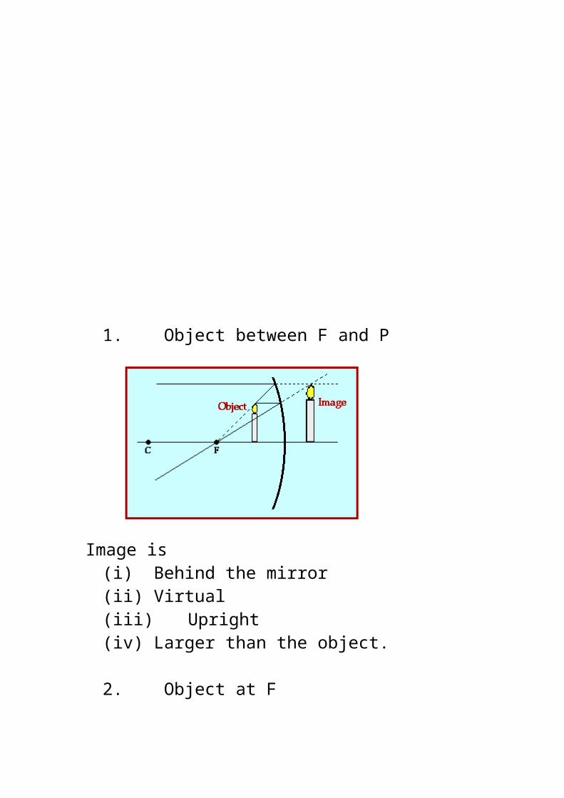
1. Object between F and P
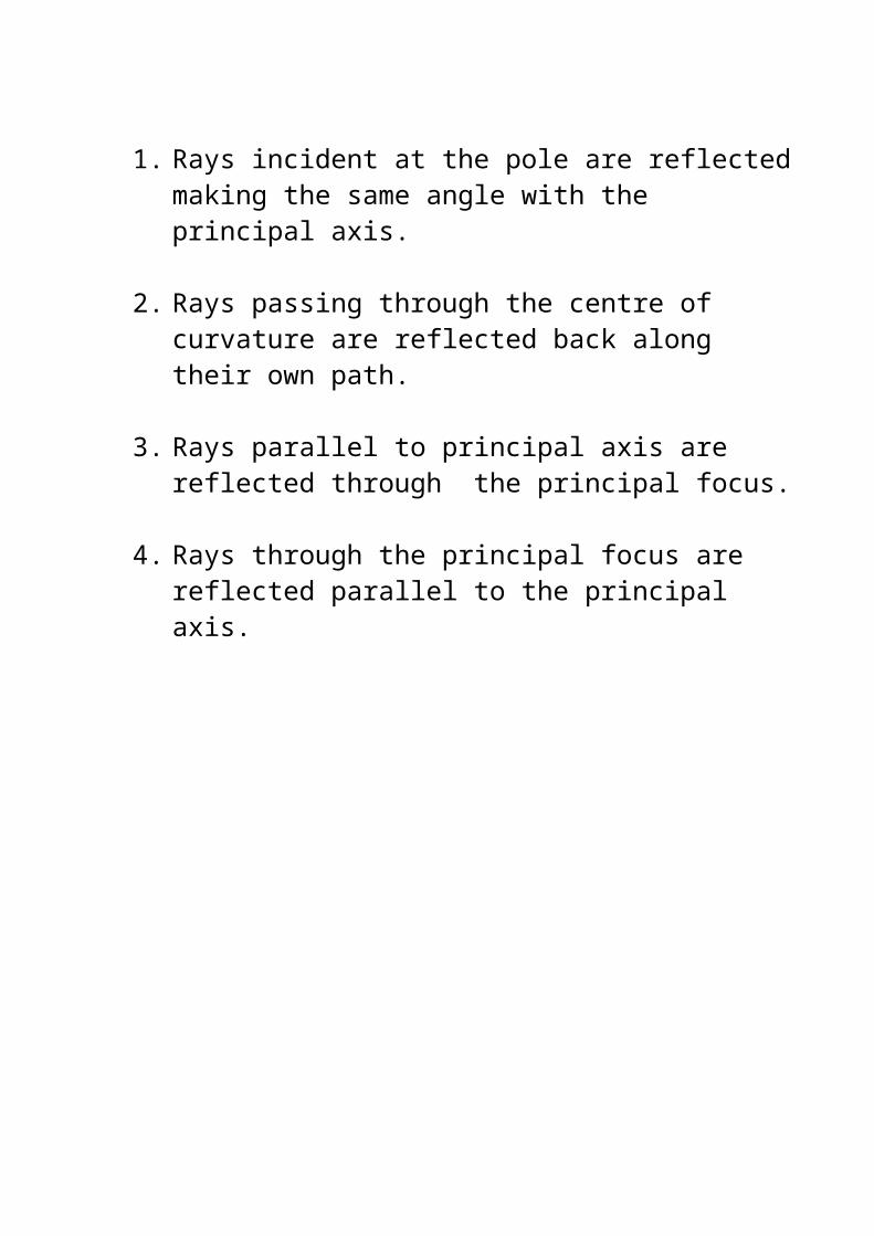
Image is(i) Behind the mirror(ii) Virtual(iii) Upright(iv) Larger than the object.
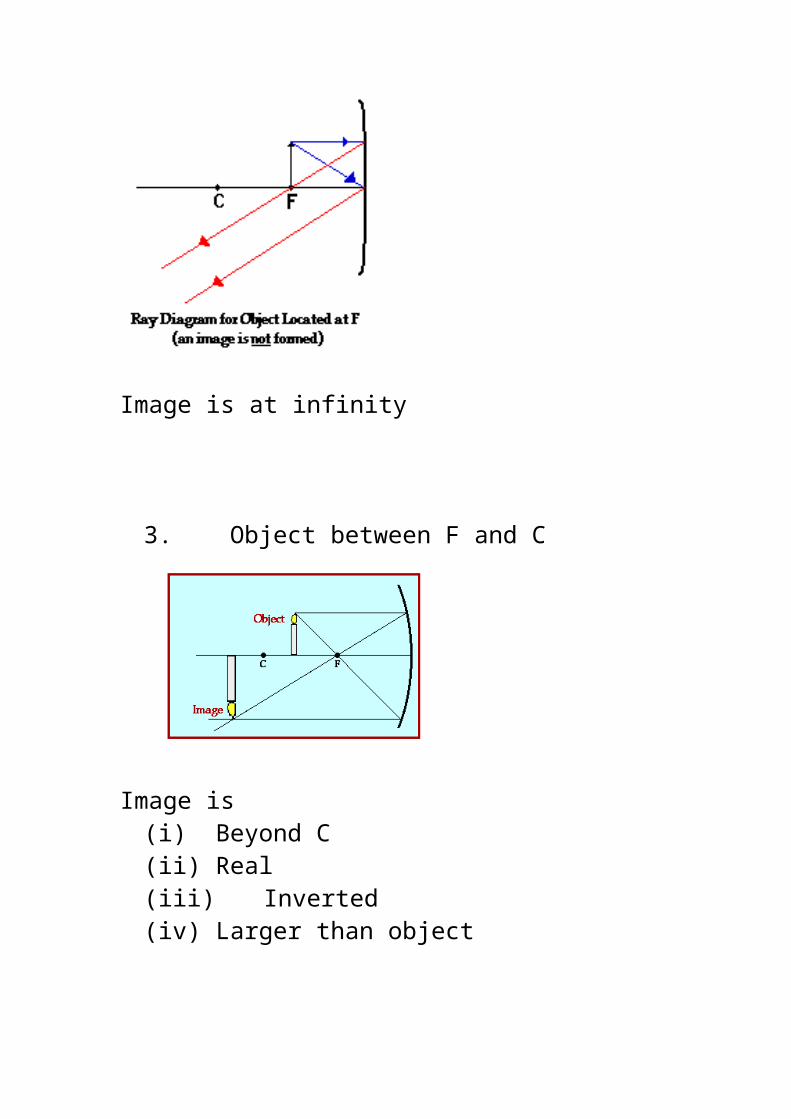
2. Object at F
Image is at infinity
3. Object between F and C
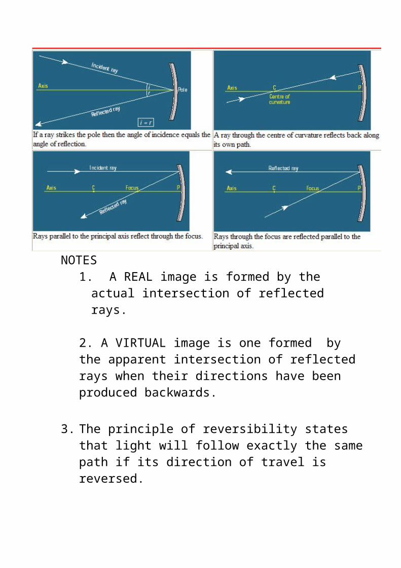
Image is (i) Beyond C(ii) Real(iii) Inverted(iv) Larger than object
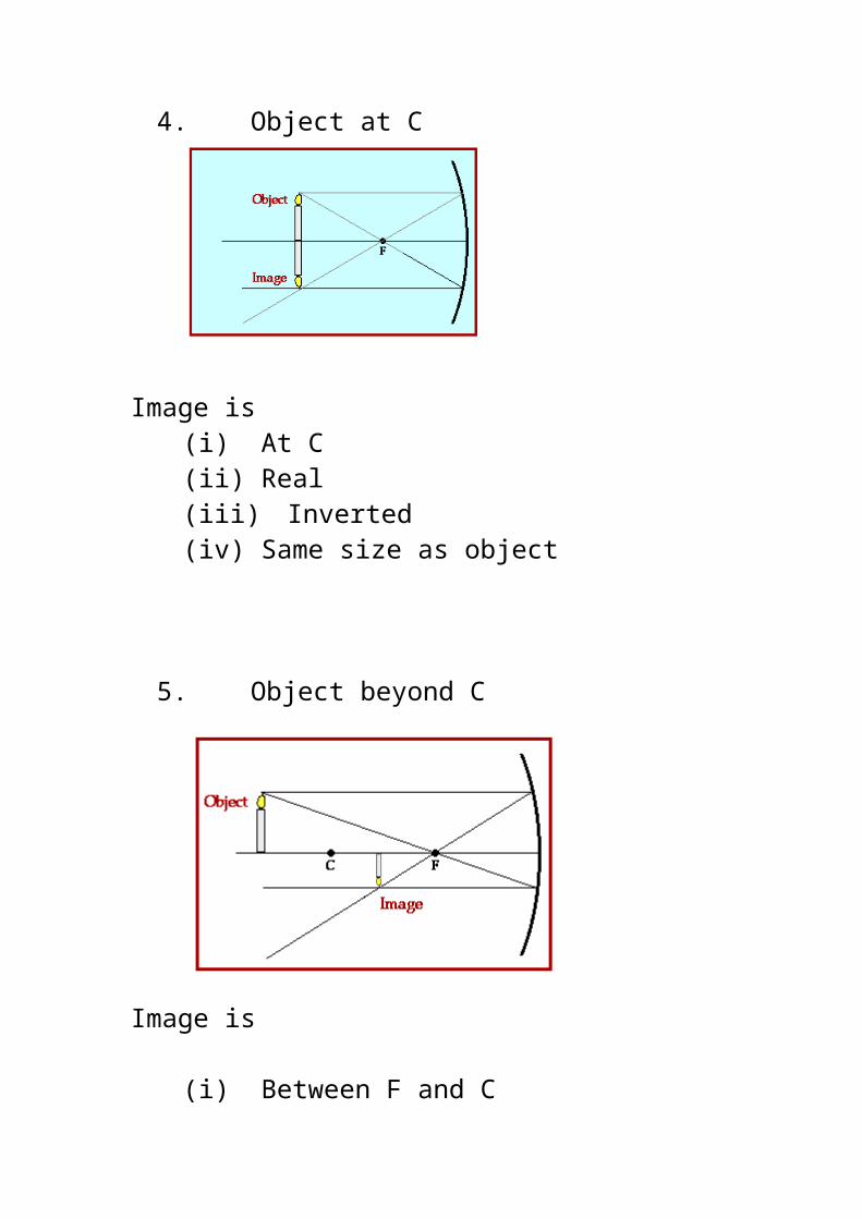
4. Object at C
Image is (i) At C(ii) Real(iii) Inverted(iv) Same size as object
5. Object beyond C
Image is
(i) Between F and C(ii) Real(iii) Inverted(iv) Smaller than object
6. Object at infinity
Image
(i) At F(ii) Real(iii) Inverted(iv) Smaller than object
Images in a convex mirror
Experiments show that the image formed in a convex mirror is always
(i) Virtual (ii) Upright(iii) Smaller than object
Regardless of where the object is located.
Therefore If the image is REAL the mirror is CONCAVE
If the image is VIRTUAL the mirror is
CONCAVE IF THE IMAGE IS LARGERAND CONVEX IF THE IMAGE IS SMALLER
Summary Mirrors Concave
a)Distant object
RealInvertedSmaller than objectAt F
b) Object beyond C
RealInvertedSmallerBetween C and F
c) Object at C
RealInvertedSame size as objectAt C
d) Object between C and F
e) Object between F and P
RealInvertedLargerBeyond C
VirtualErectLarger than objectBehind mirror
f) Object at FNo imageReflected raysare parallel
Images formed by a diverging spherical mirrorregardless of object position IMAGE ISVirtualErectSmaller than objectBehind mirror between F and P
MIRROR EQUATION
All distance values are measured with the mirror as the origin i.e. the pole P We use the following symbols
u = distance from the object to the mirror
v = distance from the image to the mirror
f = focal length distance from focus to mirror
For a spherical mirror it can be proved that
and also that the magnification m
A convention that we can use for mirrors is the REAL IS POSITIVE convention It is that any distance from a real object is taken as a positive value and any virtual distance is given a negative value.REAL +VE AND VIRTUAL _-VE
Concave mirror Real focus so f is +veConvex mirror Virtual focus so f is –ve
PROBLEM SHEET MIRROR FORMULA
Question 1. A concave mirror has a radius of curvature of 40 cm. A real object 5 cm high is placed 30 cm in front of the mirror (i)calculate the position and height of the image. Is the image real or virtual? (ii) locate the image using ray tracing (iii) repeat the calculations if the object is placed 60 cm from the mirror (ii) repeat for a convex mirror.
Question 2. An object is placed 25 cm from a concave mirror of radius 80 cm. (i) Determine the position relative size and type of image that is produced (ii) repeat for a convex mirror(iii) show the ray tracing
Question 3. (i) What type of mirror should be used in order to give an erect image 1/5 th the size of an object placed 15 cm in front of it? (ii) calculate the focal length of the mirror.
Question 4. It is desired to cast the image of a lamp magnified 5 times upon a wall 12 m from the lamp. What kind of mirror is required and what is its focal length ?