lecture 1 power quality by: syahrul ashikin azmi school of electrical system engineering
TRANSCRIPT
LECTURE 1
POWER QUALITY
By:Syahrul Ashikin Azmi
School of Electrical System Engineering
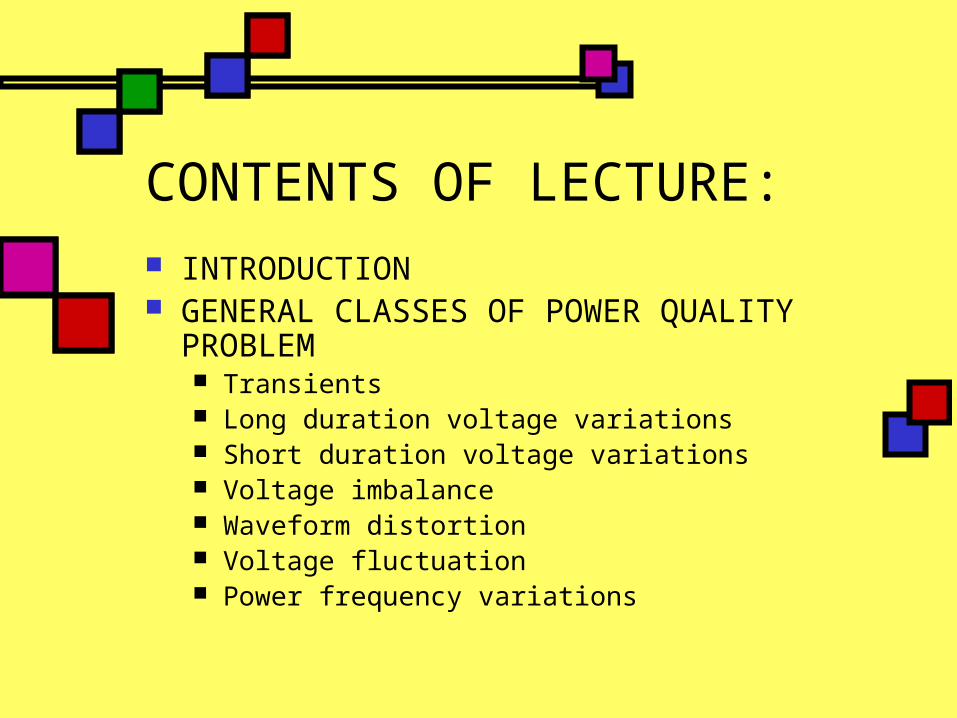
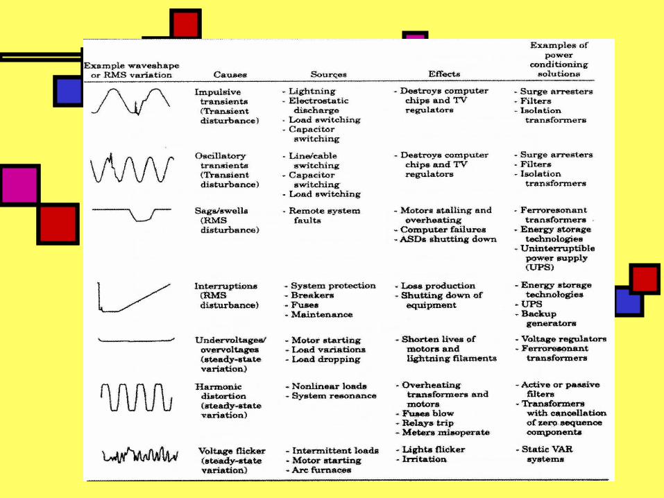
CONTENTS OF LECTURE: INTRODUCTION GENERAL CLASSES OF POWER QUALITY
PROBLEM Transients Long duration voltage variations Short duration voltage variations Voltage imbalance Waveform distortion Voltage fluctuation Power frequency variations
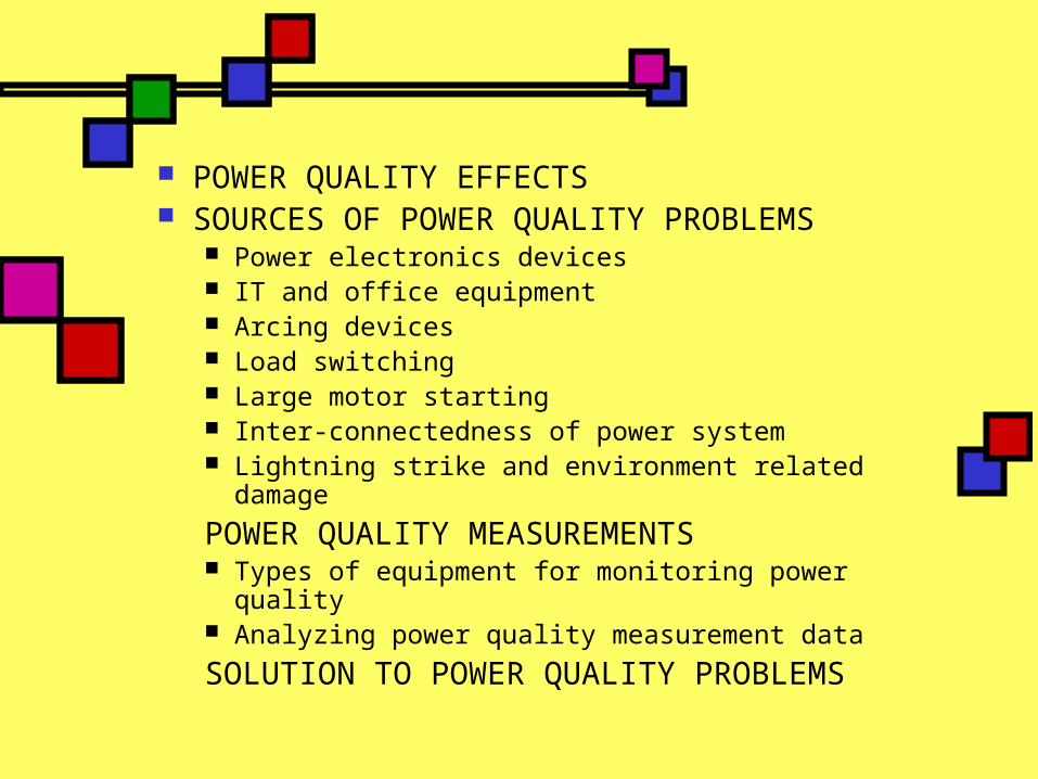
POWER QUALITY EFFECTS SOURCES OF POWER QUALITY PROBLEMS
Power electronics devices IT and office equipment Arcing devices Load switching Large motor starting Inter-connectedness of power system Lightning strike and environment related
damage
POWER QUALITY MEASUREMENTS Types of equipment for monitoring power quality Analyzing power quality measurement data
SOLUTION TO POWER QUALITY PROBLEMS

An introduction..power quality Aim of electric power system: to generate
electrical energy and to deliver this energy to end-user equipment at an acceptable voltage.
Power quality becoming important to electricity consumers at all levels of usage.
The end-users are now more concerned to protect their sensitive loads from power quality disturbances by installing protection equipment.

Definition of Power quality problem: any power problem manifested in voltage, current or frequency deviations that result in failure or mal-operation of customer equipment.
In most cases, power quality is the quality of the voltage that is being addressed.
WHY? This is because the supply system can only control the quality of voltage; it has no control over the currents that some particular loads might draw. Thus, the standards in power quality area are devoted to maintaining supply voltage within certain limits.


cont.. From IEEE, power quality is “a
concept of powering and grounding sensitive electronic equipment in a manner suitable for the equipment.”
Another definition, “Power quality is a set of electrical boundaries that allows a piece of equipment to function in its intended manner without significant loss of performance or life expectancy.”

Need for power quality..
Sensitive loads For i.e. computers and microprocessor that
include electronic controlled devices (adjustable-speed drive, scanner, fax and telecommunication equipment).
The brain of computer is integrated circuit (IC) chips. Chip is sensitive to changes in power supply.
Use on and off voltages and timing provided by supply to store and manipulate data in microp.
Any deviation from voltage can cause data to be corrupted or erased.

POWER QUALITY STANDARDS IEEE P1433: Power quality definitions IEEE P1453: Voltage flicker IEEE P1564: Voltage sag indices IEEE 1159: Recommended practice for monitoring
electric power quality IEEE 519: Recommended practices and
requirements for harmonic control in electrical power system
IEC SC77A/WG1: Harmonics and other low frequency disturbances
IEC TC77/WG1: Terminology IEC SC77A/WG8: Electromagnetic interference
related to the network frequency IEC SC77A/WG9: Power quality measurement
methods
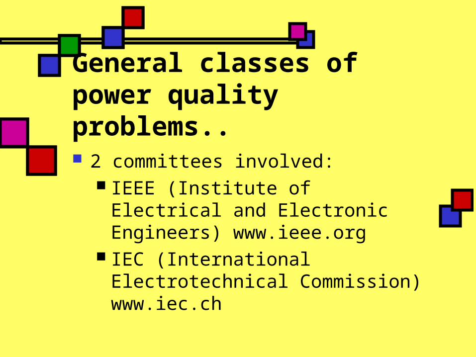
General classes of power quality problems.. 2 committees involved:
IEEE (Institute of Electrical and Electronic Engineers) www.ieee.org
IEC (International Electrotechnical Commission) www.iec.ch

IEC Standard for PQ classes

IEEE Standard of PQ classes

Refer IEEE standard table in notes (word format) of categories and characteristic of power system electromagnetic phenomena.
Transients: undesirable momentary deviation of the supply voltage or load current. Also known as surges or spikes.
2 categories of transients: impulsive and oscillatory Impulsive transients: a sudden, non-power
frequency change in the steady-state condition of voltage, current or both, that is unidirectional in polarity (either +ve or –ve).
Oscillatory transients: same definition as impulsive but the only different is bidirectional in polarity (includes both +ve or –ve values).
High-frequency oscillatory transient- greater than 500kHz
Medium-frequency oscillatory transient – between 5kHz to 500kHz
Low-frequency oscillatory transient – less than 5kHz.
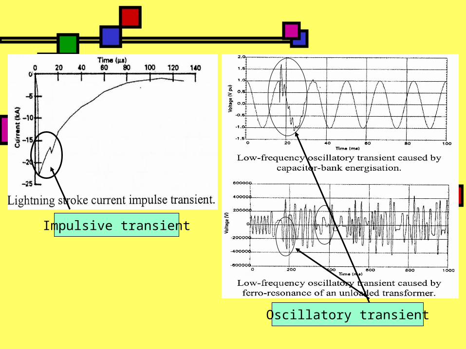
Impulsive transient
Oscillatory transient

Short duration voltage variation: interruption, sag and swell. Each type can be designated as instantaneous(0.01-0.5 sec), momentary (0.5-3 sec) or temporary (3-60 sec) Interruption - a reduction in the supply voltage,
or load current, to a level less than 0.1 p.u for a time less than 1 minute. It can caused by system faults, system equipment failures or control and protection malfunctions.
interruption

Voltage sags Decrease to between 0.1 to 0.9 p.u. in rms
voltage at the power frequency for durations from 0.5 cycles to 1 minute. Also called voltage dips. Caused by faults, increased load demand and transitional events such as large motor starting.
Voltage sag

Voltage sag

Voltage swell An increase in rms voltage in the range of 1.1
to 1.8 p.u. for duration from 0.5 cycles to 1 minute. Also called momentary overvoltage. Caused by system faults, load switching and capacitor switching.
Instantaneous voltage swell caused
by a SLG fault.

Long duration voltage variations: voltage deviation longer than 1 min.
3 types: Overvoltage - An increase in the rms ac
voltage greater than 110% at power frequency for duration more than 1 minute
Undervoltage - A decrease in rms ac voltage to less than 90% at power frequency for duration more than 1 minute
Sustained interruption - When voltage is 0 for duration more than 1 minute.

Voltage imbalance Deviation of each phase from the average
voltage of all three phases. Most equipment can tolerate voltage imbalance of
2%. Can cause network problems such as mal-
operation of protection relays and voltage regulation equipment, and also overheat of motor and transformer.
Waveform distortion Steady-state deviation from an ideal sine
wave of power frequency. 5 primary types of waveform distortion: DC
offset, harmonics, inter-harmonics, notching and noise.
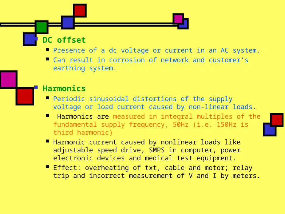
DC offset Presence of a dc voltage or current in an AC system. Can result in corrosion of network and customer’s
earthing system.
Harmonics Periodic sinusoidal distortions of the supply voltage or
load current caused by non-linear loads. Harmonics are measured in integral multiples of the
fundamental supply frequency, 50Hz (i.e. 150Hz is third harmonic)
Harmonic current caused by nonlinear loads like adjustable speed drive, SMPS in computer, power electronic devices and medical test equipment.
Effect: overheating of txt, cable and motor; relay trip and incorrect measurement of V and I by meters.

Nonlinear load waveform and harmonic content
Creation of nonlinear waveform by adding fundamental and thirdharmonic frequency waveform
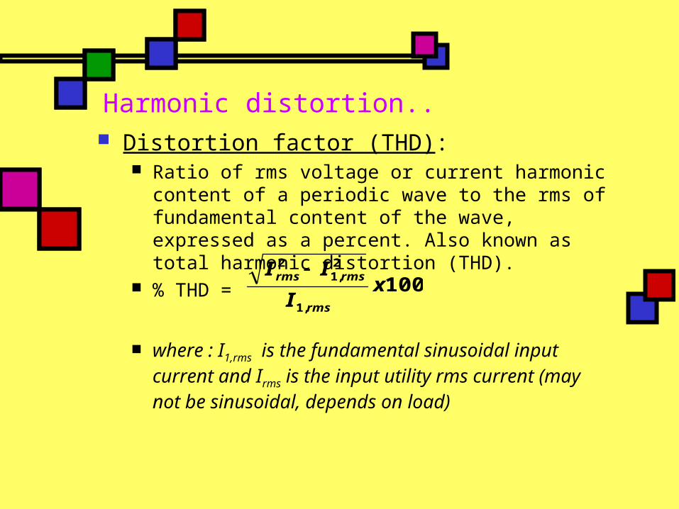
Harmonic distortion.. Distortion factor (THD):
Ratio of rms voltage or current harmonic content of a periodic wave to the rms of fundamental content of the wave, expressed as a percent. Also known as total harmonic distortion (THD).
% THD =
where : I1,rms is the fundamental sinusoidal input current and Irms is the input utility rms current (may not be sinusoidal, depends on load)
100,1
2,1
2
xI
II
rms
rmsrms

Harmonic distortion.. Displacement power factor (DPF): Ratio between active power (W) to apparent power
(VA) of the fundamental wave. DPF is same as PF in linear circuit with sinusoidal V and I. DPF is cosine of displacement angle between V and I waveform.
DPF = cos Φ

Power factor (PF): Ratio of total active power to total
apparent power of composite wave including all harmonic components.
DPFTHD
DPFI
IPF
s
s
2
1
1
1

Inter-harmonics Caused by waveforms that have frequency
components that are not integral multiples of the fundamental frequency, 50Hz.
The effects of inter-harmonics are light flicker, audible noise in tv sets, radios and audio equipment, and vibration in rotating induction machines.
Notching It is a periodic voltage disturbance caused
by normal operation of power electronic devices when current is commutated from one phase to another (two phases of supply are effectively short-circuited for a short time).

Electrical Noise Caused by a low voltage, high frequency (but lower
than 200Hz) signal superimposed on 60Hz fundamental waveform.
Cause: HV lines, start up of large motor, radio and TV station, SMPS, fluorescent light and power electronic devices.
Notching

Electrical noise adds “hash” or mess onto the fundamental sine wave
Fundamental sine wave
Noise

Voltage fluctuation Rapid changes in voltage within the allowable
limits of the nominal voltage, e.g. 0.9 to 1.1 p.u. Cause lamps to blink rapidly, often referred to as
“flicker” and is visible to human eyes at flickering frequencies of 6-8Hz.
Use static VAR controller (SVCs) to control voltage fluctuation frequency by controlling amount of reactive power supplied to the equipment (i.e. arc furnaces).
Power frequency variation Deviation of power system fundamental
frequency from its nominal value (50Hz to 60Hz).
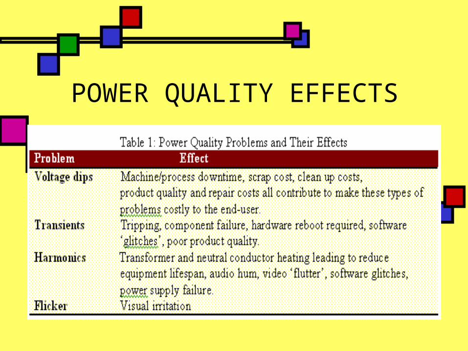
POWER QUALITY EFFECTS

SOURCES OF POWER QUALITY PROBLEMS..
Nonlinear load Any piece of equipment or appliances that increases
and reduces its consumption of electricity Example: power electronic devices, adjustable speed
drive, electronic ballast for fluorescent lamp and power supply for welding machine.
Wt nonlinear load, current and voltage do not follow each other linearly. Occur when load is not a pure resistance or inductive; instead it has electronic component to control the function of equipment to meet the requirement of load.
Result in creating harmonic distortion that cause overheating of equipment and can be susceptible to voltage dips (sag) if not adequately protected.

IT and office equipment (sensitive loads) The brain of computer is integrated circuit (IC)
chips. Chip is sensitive to changes in power supply.
Computers, microprocessors, consumer electronic and telecommunication appliances used power supplies that consists of a switched mode power supply (SMPS) and are the cause of a significant increase in the level of 3rd, 5th and 7th harmonic voltage distortion.
Any deviation from voltage can cause data to be corrupted or erased.

ITIC (CBEMA) Curve

Arcing device Electric arc furnaces, arc welders and
electric discharge lamps are all forms of electric arcing device. These devices are highly non-linear loads.
All arcing devices are sources of harmonic distortion.
Load switching This type of transient might occur as the
result of switching in a heavy single-phase load.
Other equipment can be protected from these switching transients by electrically isolating them from the affecting equipment.

Large motor starting Dynamic nature of induction machines means that
they draw current depending on the mode of operation.
During starting, this current can be as high as six times the normal rated current. This increased loading on the local network that has the effect of causing a voltage dip.
Most modern motors employ a sophisticated power electronic converter ‘drive’, which control the motor’s starting current to a reasonable level.
Some lower cost types of motor use series capacitors or resistors to reduce the starting current. These components are then switched out once the motor’s rated speed has been reached.
Autotransformers are used to start some older motors. These have a variable secondary winding that allows the motor stator voltage to be controlled and hence the current drawn from the supply.

Inter-connected of power system Increasing levels of interconnection in power
system is predicted in the future are likely to have an effect on power quality. The problem can propagate and difficult to isolate. Harmonics and flicker are examples of power quality problems that can be transferred from a utility to another through interconnection.
Lightning Strike and Environment Related Damage
Lightning strikes are a cause of transient overvoltages often leading to faults on the electricity supply network.
Lightning strikes that hit overhead lines often cause ‘flash-over’ to neighbouring conductors as the insulators break down. The strike will therefore not only consist of a transient overvoltage but also fault-clearing interruptions and dips.
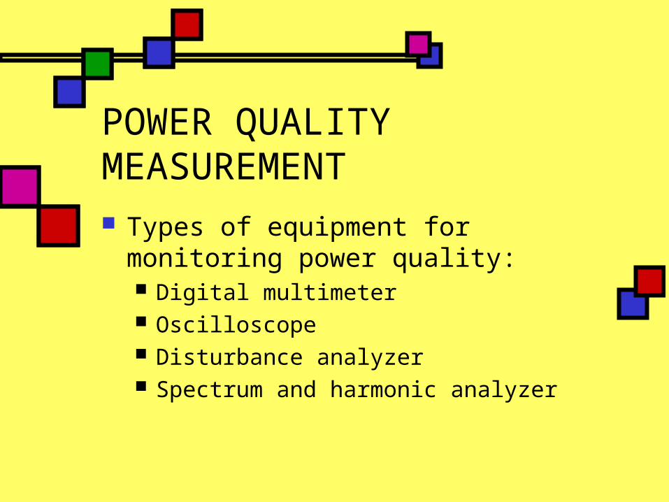
POWER QUALITY MEASUREMENT Types of equipment for monitoring
power quality: Digital multimeter Oscilloscope Disturbance analyzer Spectrum and harmonic analyzer
SOLUTION TO POWER QUALITY PROBLEM.. Earthing practices
Power quality problem is caused by incorrect earthing practices.
Verification of earthing arrangement should be conducted in power quality investigation.
Reducing the number of faults For examples tree-trimming, animal
guards, shielding wires and replacing overhead lines by underground lines.
Normally used to solve voltage dip problem.
Faster fault clearing Need to improve protection techniques. Development of a new generation of
circuit breakers and relay at the transmission level.

Static breaker Allow the isolation of faulted circuits in
the shortest possible time frame, while other nearby loads will improve the power quality of the network.
Transfer switch Used to transfer a load connection
from one supply to another, allowing the choice of two supplies for the load (or sub network).
One of the supply will handle the power disturbances on the system whereas the other one will be automatically switched on to reduce the possibility of supply disruption to the load.

Local or embedded generation A form of local generation, i.e.
diesel generator, can be connected to allow for any shortfall (or loss) in the main capacity and also to provide ride-through for power quality disturbances.
Expensive solution since the cost to keep a diesel generator running online.

Mitigation equipment at the interface.. UPS (Uninterruptible
power supply) Standby, online
and hybrid UPS Dual feeder with
static transfer Static VAR
Compensator (SVC) STATCOM (static
synchronous compensator)
DVR (dynamic voltage restorer)
Various line-voltage regulators Constant voltage
transformer Transformer with
tap changer Harmonic filter
Passive and active filters
Motor-generator sets Surge suppressor Isolation transformer Noise filter Energy storage
system

UNINTERRUPTIBLEPOWER SUPPLY
1. STANDBY UPS2. ONLINE UPS3. HYBRID UPS
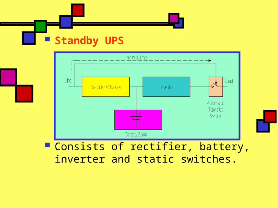
Standby UPS
Consists of rectifier, battery, inverter and static switches.
Rectifier / Charger Inverter
Battery Bank
Load
AutomaticTransferSwitch
Line
Normal Line

Static switch is controlled to allow load to be fed from main supply.
Switch open and close respectively below some predetermined level.
Then, the load will be fed from battery via inverter to ensure continuity of supply to the load.
Inverter output of a standby UPS must always operate in synchronism with the supply frequency to ensure a smooth transition from one supply to the other.
STANDBY UPS

Rectifier / Charger Inverter
Battery Bank
Load
ManualBypass
Line
ONLINE UPS
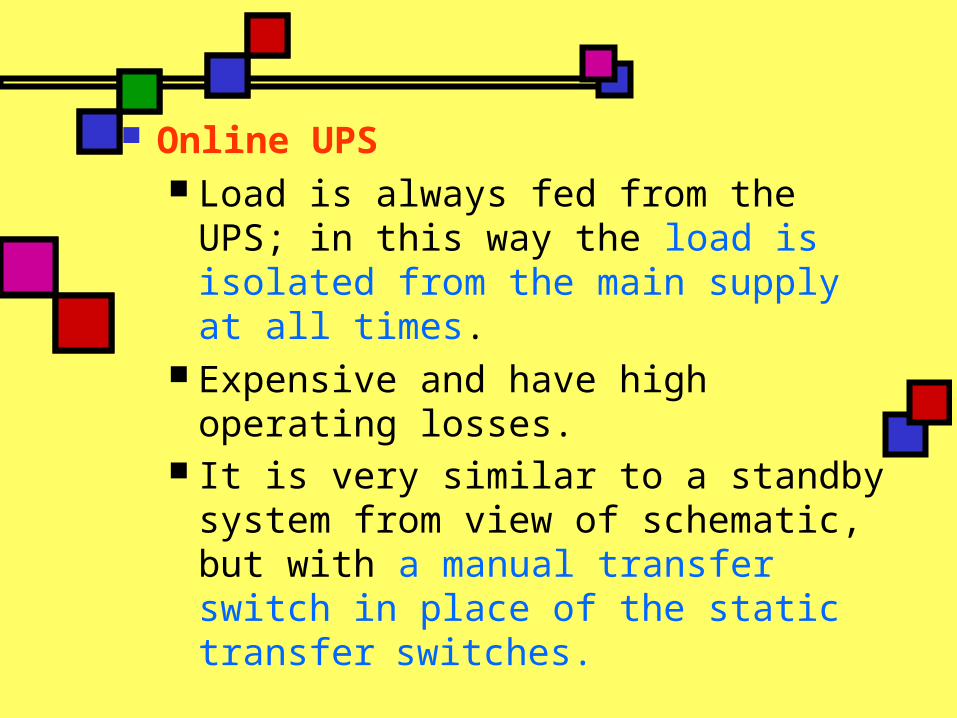
Online UPS Load is always fed from the UPS; in
this way the load is isolated from the main supply at all times.
Expensive and have high operating losses.
It is very similar to a standby system from view of schematic, but with a manual transfer switch in place of the static transfer switches.

Rectifier / Charger Inverter
Battery Bank
FerroresonantTransformer Load
Line
Normal Line
Hybrid UPS
HYBRID UPS
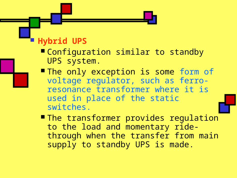
Hybrid UPS Configuration similar to standby UPS
system. The only exception is some form of
voltage regulator, such as ferro-resonance transformer where it is used in place of the static switches.
The transformer provides regulation to the load and momentary ride-through when the transfer from main supply to standby UPS is made.

DUAL FEEDERS WITHSTATIC TRANSFER
1. STATIC SVCs2. STATCOM
3. DVR

Supply of VARs by static VAR compensator (SVC) Used to supply reactive power (VAR)
to the supply system. The heart of SVC is the thyristor
valve, consisting of ‘back-to-back’connected, high-power thyristors in series in order to obtain the required operating voltage.
The thyristor valve control the current either through reactors to form a thyristor controlled reactor (TCR) or capacitors to form thyristor switched capacitors (TSC) or combination of both TCR and TSC.

Thyristor controlled reactor (TCR) A reactor and a thyristor valve are incorporated in
each single-phase branch. The power is changed by controlling the current
through the reactor by means of the thyristor valve.
The on-state interval is controlled by delaying the firing of the thyristor valve in relation to the natural current zero.
A TCR is used together with a fixed capacitor bank when reactive power generation is required.
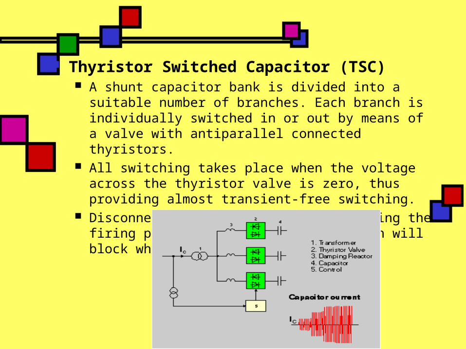
Thyristor Switched Capacitor (TSC) A shunt capacitor bank is divided into a suitable
number of branches. Each branch is individually switched in or out by means of a valve with antiparallel connected thyristors.
All switching takes place when the voltage across the thyristor valve is zero, thus providing almost transient-free switching.
Disconnection is effected by suppressing the firing pulses to the thyristors, which will block when the current reaches zero.

Thyristor Switched Capacitor / Thyristor controlled Reactor (TSC / TCR) A combination of TSC and TCR is, in the
majority of cases, the optimum solution. With this combination, continuous variable
reactive power is obtained throughout the complete control range as well as full control of both the inductive and the capacitive parts of the compensator.
This is a very advantageous feature permitting optimum performance during large disturbances in the power system.

Configuration of TCR and TSR

With the SVC (static VAR compensator), the control of current is achieved by controlling the output voltage magnitude of an inverter.
SVC’s are used to absorb or inject reactive current to eliminate the harmonic distorting current drawn by non-linear loads.
3 Siemens SVC installed at Drakelow substation,
Derbyshire, UK and its single line diagram

Static synchronous compensator (STATCOM) STATCOM is a shunt connected, solid state
device that used power electronics to control power flow and improve transient stability on power grids (or power system network).
It also regulates voltage at its terminal by controlling the amount of reactive power injected into or absorbed from the power system.
When system voltage is low, the STATCOM generates reactive power (STATCOM capacitive).
When system voltage is high, it absorbs reactive power (STATCOM inductive).

Variation of reactive power is performed by Voltage-Sourced Converter (VSC) connected on the secondary side of a coupling transformer.
The VSC uses forced-commutated power electronic devices (GTOs or IGBTs) to synthesize a voltage generated by the VSC from a DC voltage source.
The GTO (gate-turn-off thyristor) is used for higher voltage application while IGBT (integrated gate bipolar transistor) for lower voltage.

V-I characteristic of STATCOM and SVC

STATCOM offer better voltage support and improved transient stability margin by providing more VARs at lower voltages.
This is because the maximum capacitive power generated by a SVC is proportional to the square of the system voltage (constant susceptance) while the maximum capacitive power generated by a STATCOM decreases linearly with voltage (constant current).
Since no large capacitors or reactors are used to generate VARs, STATCOM provides very fast response (no delay associate with thyristor firing) and greater stability to variations in system impedance.
Harmonic elimination by selective firing of the GTOs means that STATCOM has further advantages over the SVC and can be used as an active filter.

Dynamic voltage restorer (DVR) Primary function: to minimize the voltage sags on lines
that cater to sensitive equipment. Consists of VSC placed in series with the
load/distribution feeder by means of an injection transformer.
It can inject voltages of controllable amplitude, phase angle and frequency into the feeder, thus restoring voltage to critical load during sag.
DVR functions as a filter between the transmission line and the facility, thus enabling the facility to continuously receive clean power. It is primarily responsible for restoring the quality of voltage delivered to the end user when the voltage from the source is not appropriate to be used for sensitive loads.
Usage of DVR enables consumers to isolate and protect themselves from transients and disturbances caused by sags and swells on the transmission lines or distribution network.

DVR operating diagram
This solution is costly but popularly used in large industrial consumers (a few MVA) that have very high power quality demands.
It allows protection of the entire plant from voltage sag through installation of only one device.
The major industries that are likely to benefit the most from DVRs are: Utilities (transmission and distribution companies) Process industries (semiconductor plants, paper
mills, plastic manufacturers) Automotive manufacturers Chemical plants Electronics (consumer electronic and computer
manufacturers) Mining industry Steel plants

Benefit of DVR: Reduce losses associated with irregularities in the
production process resulting from power disturbances.
A large part of the industrial machinery makes use of sophisticated electronics that are quite sensitive to power disturbances. DVR plays a key role in ensuring the smooth functioning of such equipments.
Power disturbances can lead to irregularities or in a worst-case scenario, stoppage of production processes. Whenever any kind of aberration in power is detected, DVRs reduce the potential shutdown time for equipment within facilities that ultimately saves a lot of time and money.

Benefit of DVR (cont.): Can also be used to tackle the problem of
harmonics caused by non-linear load machinery in manufacturing facilities. If not corrected in time, the harmonic voltages can spill over to the office power and cut into the productivity.
The insulation wear on transformers, motors and drivers caused by power irregularities can also be reduced by DVR.

VARIOUS LINE-VOLTAGEREGULATOR
1. CONSTANT VOLTAGE TRANSFORMER2. TRANSFORMER WITH TAP CHANGER

Transformer based solution Ferro-resonant txt has 1:1 turns ratio and
with a core that is highly magnetized close to saturation under normal operation.
This will provide an output voltage which is not affected by input voltage variations hence the output is not significantly affected by voltage sag.
In actual design, a capacitor connected to secondary winding to set the operating point above the knee of saturation curve.
Suitable for low-power, constant loads

Typical circuit for a ferro-resonant transformer

Transformer with electronic tap changers Electronic tap changers can be mounted on txt
for sensitive load to change its turn ratio according to change in input voltage.
They are connected in series on the distribution feeder and placed between supply and load.
Part of secondary winding is divided into number of sections which are connected or disconnected by fast static switches to allow regulation of secondary voltage in steps.
This will allow the output voltage to be brought back to level above 90% of nominal value even during severe sags.
Thyristor-based switches only turn on once per cycle, thus accomplish the compensation with a time delay of at least one half cycle.

Transformer with electronic tap changers

HARMONIC FILTERS
1. ACTIVE FILTER2. PASSIVE FILTER

Harmonic filter Filter consist of inductors and/or capacitors connected together
to block harmonic currents or shunt them to ground.
2 basic configuration: series and shunt filters.
Series filter consist of capacitor and inductor connected in parallel with each other but in series with load. Provides high-impedance path for harmonic current & block them from reaching power supply but allow fundamental 50/60Hz current to pass through.
Shunt filter consists of capacitor and inductor connected in series with each other but in parallel with the load. Provides low-impedance path for harmonic current and diverts them harmlessly to ground. Less expensive and more commonly used.
Passive filter A simple filter consist of discrete (static) capacitors
and/or inductors. Designed to handle specific harmonics. Do not respond to changes in frequency. Referred as trap or choke. Ineffective when harmonic changes due to load changes.
Active filter Referred as active power line conditioners (APLCs). It condition harmonic currents rather than block or divert
them. Use electronic (bridge inverter or rectifier) to monitor &
sense harmonic currents and create counter-harmonic current. Then, inject counterharmonic current to cancel out harmonic current generated by load.
Also regulate sag and swell by eliminate source voltage harmonic.
Most effective in compensating for unknown or changing harmonics.

Motor-generator sets Consist of a motor supplied by power
system, a synchronous generator supplying the load and a flywheel. All connected in common axis.
The rotational energy stored in flywheel can be used to perform steady-state voltage regulation and to support voltage during disturbances.
This system has high efficiency, low initial costs and enables long duration ride through (several seconds).
Only suit in industrial environment due to its size, noise and maintenance requirements.

Motor-generator set
Surge suppressors Protect sensitive equipment from being zapped by
voltage surges or lightning strokes on power system.
If located at utility side, it is called surge or lightning arrestor. If at end user side, it is called transient voltage surge suppressor (TVSS).
Divert to ground or limit transient voltage caused by lightning or switching surges to a level that not harm equipment they are protecting.
Utilities install arresters near equipment they want to protect while end users locate TVSS inside their facilities; between power outlet and sensitive electronic equipment.
2 basic types: crowbar and voltage-clamping devices.

Noise filter Low pass filter used to prevent unwanted
frequencies from entering sensitive equipment. Combination of inductor and capacitor connected
in parallel with each other. Inductors allow low frequency fundamental signal
of 60Hz power to pass through. Capacitor in parallel with inductor divert high
frequency of common-mode and normal-mode noise to ground.
Normal-mode noise refer to noise between live wire and neutral. Common-mode noise refer to noise between live wire to ground or neutral wire to ground.
Either stand alone or part of TVSS.

Isolation transformer Isolate sensitive equipment from transients and noise
produced by utility. Consists of primary and secondary winding with magnetic
core and a grounded shield made of nonmagnetic foil located in between 2 winding.
Any noise or transient from utility is transmitted through capacitance between primary and shield and on to ground.
Prevent common-mode noise from reaching and damaging sensitive equipment. Using secondary winding with grounded wye, no common noise can reach the load.
Delta-wye txt also protect utility from triplen harmonic (3rd, 9th, 15th,..) created by end users. Txt transfer harmonic from secondary(wye) to primary (delta). Triplen harmonic remain in delta primary circulating around and generating heat in txt but not getting on utility’s system.

1. Single phase shielded isolation transformer2. Three-phase delta-wye isolation transformer
(1)
(2)

Energy storage system All electrical energy storage system have the same
basic components, interface with power system, power conditioning system, charge/discharge control and the energy storage medium itself.
Each storage medium has different characteristic, energy density, charge/discharge time, effect of repeated cycling on performance and life, cost, maintenance requirement.
Available energy storage systems: Battery/advanced battery energy storage Superconducting magnetic energy storage – used
for very critical applications but its cost limits its use to industries where the losses are great during disturbances, for example semiconductor fabrication.
Flywheel energy storage – high maintenance cost Capacitor or ultra-capacitor storage

Conclusion.. Power quality is a well-defined field with
growing interest being shown in the solution to the problems, monitoring equipment, regulations and statistical analysis of customers’ expected levels of disturbance.
As future development grow widely, the new materials and devices become available where it may be possible to provide solutions for the cause of the power quality problem rather than treat the symptoms.

Voltage sag

Voltage swell