lecture 09 dimensioning and tolerancesnrskumar/index_files... · 2013-09-03 · • functional...
TRANSCRIPT
Lecture 09
DIMENSIONING AND
TOLERANCES
Mechanical Engineering Graphics
MECH 211

Each feature of an object is dimensioned once and only once.
Dimensions should be selected to suit the function of the
object.
Dimensions should be placed in the most descriptive view of
the feature being dimensioned.
Dimensions should specify only the size of a feature. The
manufacturing method should only be specified if it is a
mandatory design requirement.
Angles shown on drawings as right angles are assumed to be
90 degrees unless otherwise specified, and they need not be
dimensioned.
Dimensioning rules

Dimensions should be located outside the boundaries of the
object whenever possible.
Dimension lines should be aligned and grouped where
possible to promote clarity and uniform appearance.
Crossed dimension lines should be avoided whenever
possible. When dimension lines must cross, they should be
unbroken.
The space between the first dimension line and the object
should be at least 3/8 inch (10mm). The space between
dimension lines should be at least ¼ inch (6mm).
There should be a visible gap between the object and the
origin of an extension line.
Dimensioning rules – Cont’d

Extension lines should extend 1/8 inch (3mm) beyond the
last dimension line.
Extension lines should be broken if they cross or are close
to arrowheads.
Leader lines used to dimension circles or arcs should be
radial.
Dimensions should be oriented to be read from the bottom
of the drawing.
Diameters are dimensioned with a numerical value
preceded by the diameter symbol.
Dimensioning rules – Cont’d
Concentric circles should be dimensioned in a longitudinal
view whenever possible.
Radii are dimensioned with a numerical value preceded by
the radius symbol.
When a dimension is given to the center of an arc or
radius, a small cross is shown at the center.
The depth of a blind hole may be specified in a note. The
depth is measured from the surface of the object to the
deepest point where the hole still measures a full diameter
in width.
Counterbored, spotfaced, or countersunk holes should be
specified in a note.
Dimensioning rules – Cont’d

Aligned Dimensions have text placed parallel to the
dimension line, with vertical dimensions read from the right
of the drawing.
Unidirectional Dimensions are read from bottom of page
Dimension figures - Direction Aligned and unidirectional dimensioning

Dimension outside the view
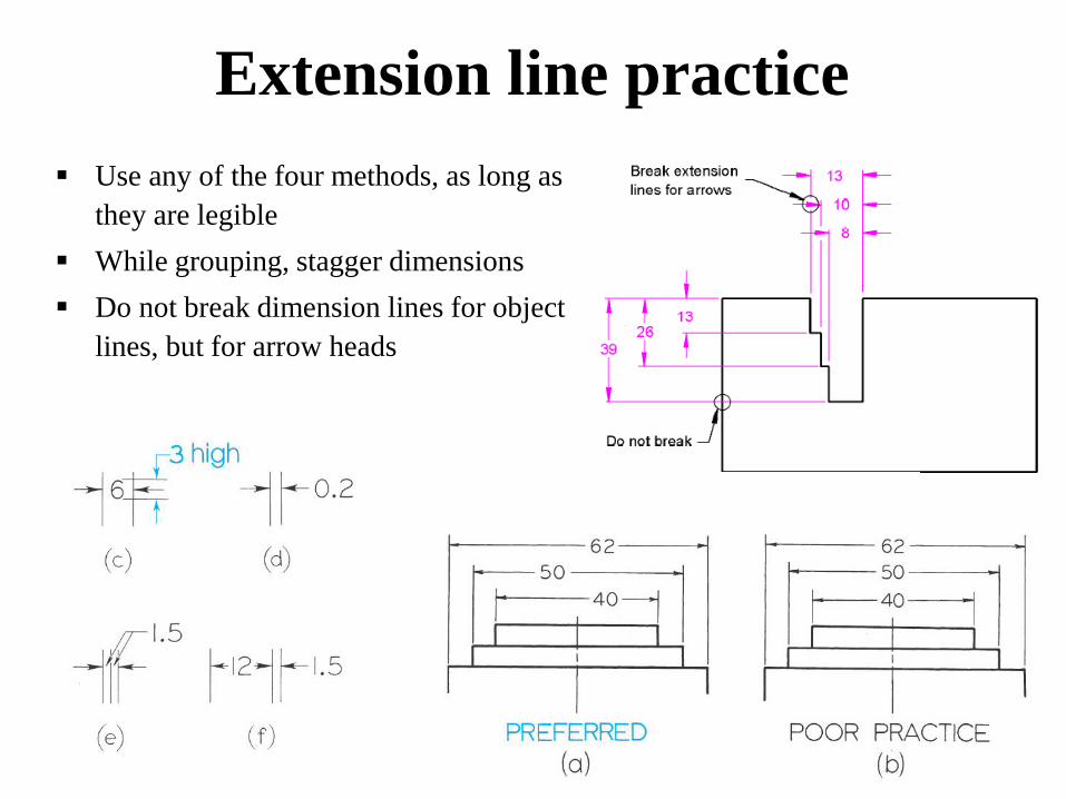
Extension line practice
Use any of the four methods, as long as
they are legible
While grouping, stagger dimensions
Do not break dimension lines for object
lines, but for arrow heads

Center line practice

More than half a circle:
diameter
Leaders to point towards centre
of the circle or arc (Radial)
Less than half a circle or arc:
radius
Radial and diametric dimensions

Dimensioning arcs Arc in dimensioned in a view where true shape is
seen
If space is available leader and the value is
located inside the arc. If not numeral alone or
including leader is moved out
Cross is indicated with or without dimensions for
centre of all arcs except small and unimportant
radii
For long radius, false center with jogged leader
can be used

Staggering dimension text Aligning dimension lines
Dimensioning chained features
• smaller dimension
should be placed
closer to the object
to avoid unnecessary
crossing

• Extension lines and line indicators are used
to detail manufacturing requirements
Detailed explanations

• All features in drawings are scaled accordingly
• Not-scaled features could be also represented but
also indicated with an underline
Not to scale dimensioning
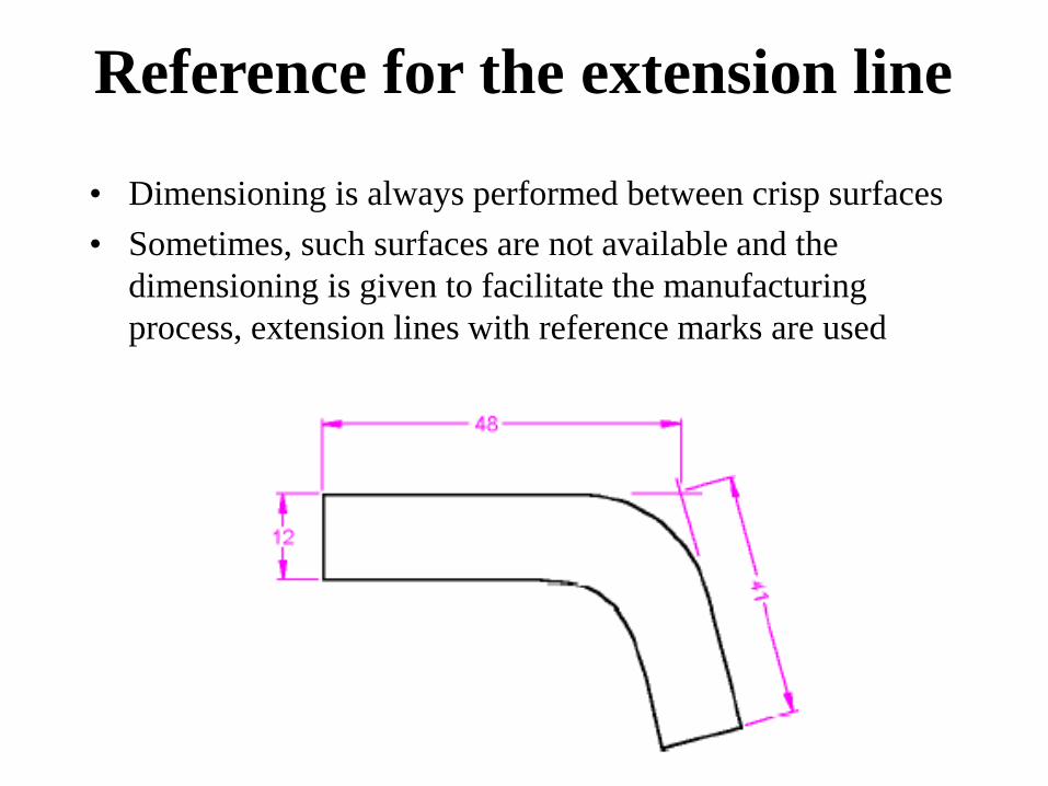
• Dimensioning is always performed between crisp surfaces
• Sometimes, such surfaces are not available and the
dimensioning is given to facilitate the manufacturing
process, extension lines with reference marks are used
Reference for the extension line

• Holes should be dimensioned in the view
that they are best seen
General dimensioning
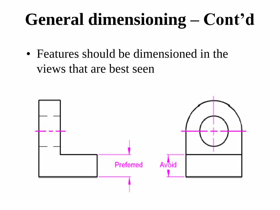
• Features should be dimensioned in the
views that are best seen
General dimensioning – Cont’d

• Do not draw a
view/section for a
feature that could be
indicated by a symbol
General dimensioning – Cont’d

General dimensioning – Cont’d
Counterbore Countersink Spotface
Section veiw
is needless as
symbols in the
topview
means this

Keyseat and keyway
General dimensioning – Cont’d
• Dimension keyseats from the bottom of the
keyseat to opposite end of the shaft
• For key seat, from top of keyway to bottom of
hole
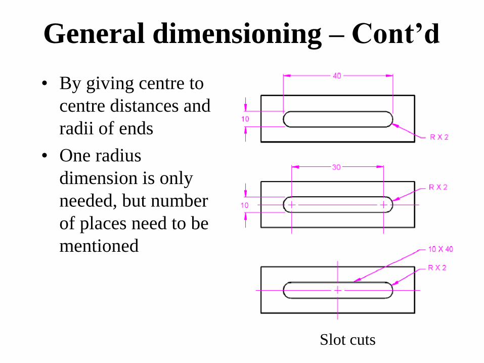
Slot cuts
General dimensioning – Cont’d
• By giving centre to
centre distances and
radii of ends
• One radius
dimension is only
needed, but number
of places need to be
mentioned

Chamfers
General dimensioning – Cont’d

Concentric circles
General dimensioning – Cont’d
• Dimensioned in the
longitudinal view

Grooves
General dimensioning – Cont’d
• Dimensioned with
local notes
• Or by showing the
dimensions of both
the depth of undercut
and the distance

Threads
General dimensioning – Cont’d
• Threads are
dimensioned with
local notes
• Internal or tapped
threads on the
circular view
• External threads on
the longitudinal view

• Both size and location dimensions have to
be provided to avoid any confusion
Size Vs. Location

Size Vs. Location
• Both size and location dimensions have to be
provided to avoid any confusion

• Each feature of an object is dimensioned once and
only once
• The location and/or size dimensions for a feature
should be placed in the view in which that feature is
most clearly seen i.e. where its shape description is
most complete
• Any dimension specified should correspond to a range
of dimensions in the final product, i.e. each dimension
should include an appropriate tolerance
Reminder
• Dimensions lines should never coincide with
object lines or other extension lines
• Dimension lines should be unbroken except for
the number between the arrowheads
• There should be a visible gap between the object
and the origin of an extension line
• Crossing of dimension lines should be avoided
wherever possible
Reminder

• Dimensions should reference object lines rather than
hidden lines
• Dimensions should be placed in spaces as close as
possible to their point of application
• When dimensions are "nested", the smaller dimension
should be placed closer to the object to avoid
unnecessary crossing
• Dimensions should be located outside the boundaries
of the object wherever possible
Reminder
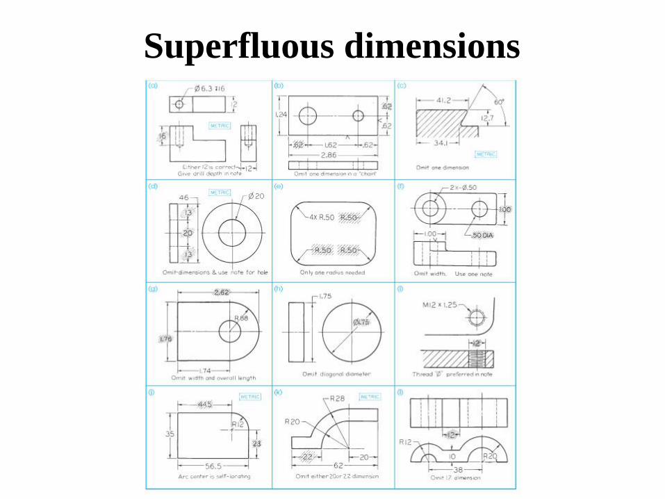
Superfluous dimensions

• Understanding of tolerances
• Selection and calculations
• Prescription of tolerances
• Tolerance of a size: the difference between
the maximum and the minimum allowed size of
the specific dimension
What is Important?
Nomenclature
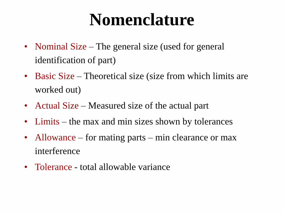
• Nominal Size – The general size (used for general
identification of part)
• Basic Size – Theoretical size (size from which limits are
worked out)
• Actual Size – Measured size of the actual part
• Limits – the max and min sizes shown by tolerances
• Allowance – for mating parts – min clearance or max
interference
• Tolerance - total allowable variance
Nomenclature
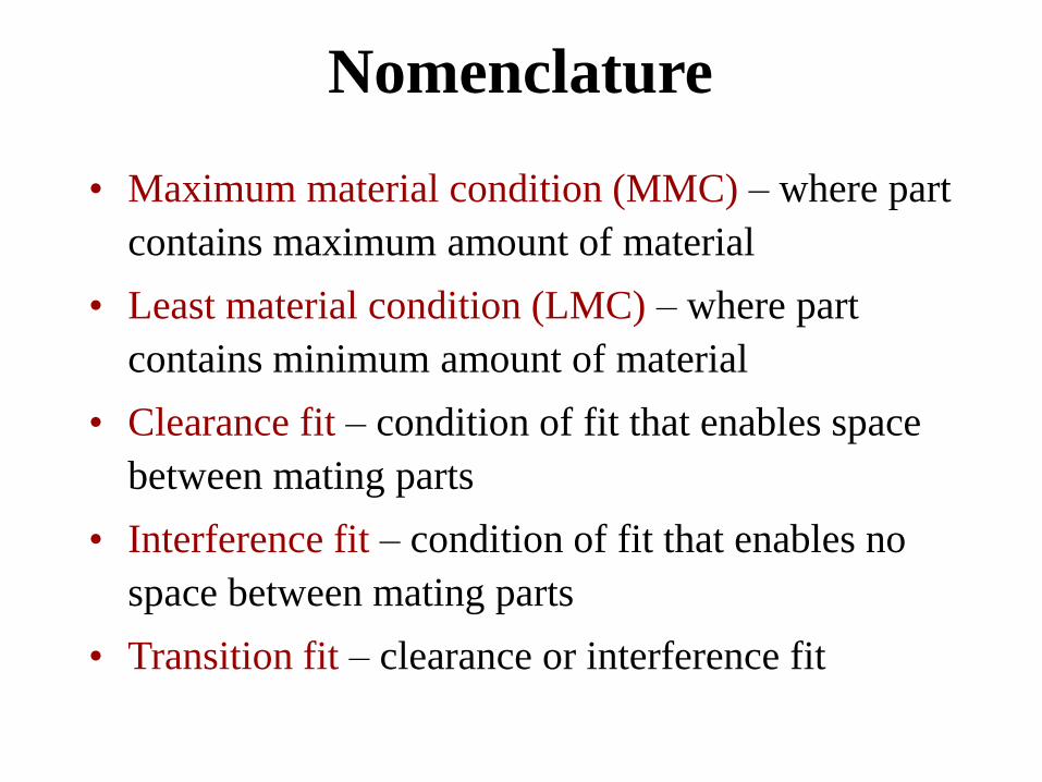
• Maximum material condition (MMC) – where part
contains maximum amount of material
• Least material condition (LMC) – where part
contains minimum amount of material
• Clearance fit – condition of fit that enables space
between mating parts
• Interference fit – condition of fit that enables no
space between mating parts
• Transition fit – clearance or interference fit

• Direct limits (limit dimensioning)
• Tolerance value (plus or minus dim)
• Unilateral Tolerances (only in one direction from basic size)
• Specific note (The * dimensions 2+0.001)
• General note (All diameters 2+0.001)
Tolerance representation

Clearance and interference fits

Transition fit
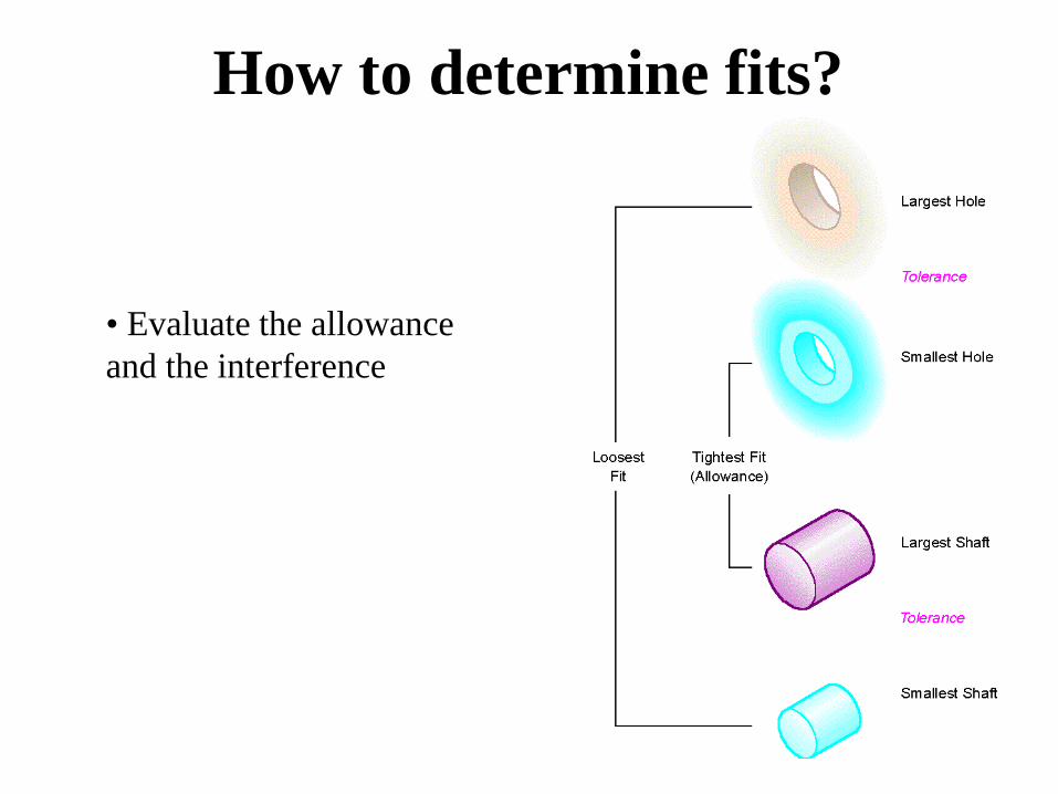
• Evaluate the allowance
and the interference
How to determine fits?

• Functional dimensioning begins with tolerancing
the most important features
• The functionality of the assembly has to be very
clearly established by the designer
• The assembly procedure as well as the
manufacturing processes involved in producing
the part must be also clear to the designer
• Tolerances should be as “coarse” as possible and
still permit satisfactory use of part – Why?
Functional dimensioning

• Tolerances taken in the same direction from one point of reference are additive – tolerances stack-up or accumulation of tolerance
• Tolerance stack-up can be eliminated by careful selection and placement of dimensions
• If Z not given, it will be governed by both X and Y (.01 instead of intended tolerance of .005)
Tolerance Stack-up

Dimensioning with respect to the base base would help
Tolerance Stack-up

Tolerancing in ISO
International tolerance (IT) Grades

Minimum hole size is the basic size
Metric preferred hole based system of fits

Limit form vs. note form tolerancing
Hole Tolerance =
.025
Shaft Tolerance =
.016
Loosest fit =
40.025-39.975 =
.050
Tightest fit =
40.000 – 39.991 =
.009

Metric Tolerances-Standard representation
• If limits are shown up and down, largest limit up
• If shown side by side, smallest limit first
• For angular dimensions, it can be in general note or it can be
mentioned similar to that of linear dimensions

• Hole Basis fit: the basic size is the minimum dia of the hole
and fit is calculated based on this
• Shaft Basis fit: the basic size is the maximum dia of the shaft
and the fit is calculated base on this
Basic hole and shaft system-Imperial size
Hole Basis Fit
Interference fit Clearance fit
Shaft Basis Fit
Interference fit Clearance fit
Basic Size .500
Largest shaft
.500
Smallest hole
.500

0.500 is the lower limit hole
0.496 is the upper limit shaft
0.004 is the ALLOWANCE
0.496 is the upper limit shaft
0.003 is the shaft tolerance
0.493 is the LOWER LIMIT SHAFT
0.500 is the lower limit hole
0.003 is the hole tolerance
0.503 is the UPPER LIMIT HOLE
0.500 is the smallest hole
0.496 is the largest shaft
0.004 is the tightest fit
0.503 is the largest hole
0.493 is the smallest shaft
0.10 is the loosest fit
.503
.500 .496 .493
Example – Run Fit
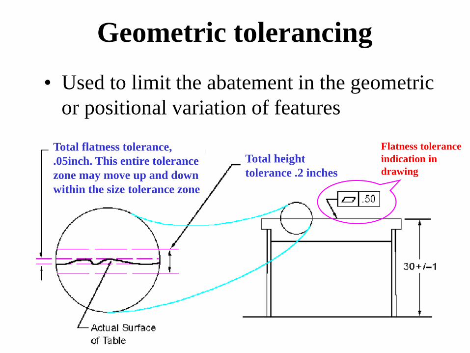
• Used to limit the abatement in the geometric
or positional variation of features
Geometric tolerancing
Total flatness tolerance,
.05inch. This entire tolerance
zone may move up and down
within the size tolerance zone
Total height
tolerance .2 inches
Flatness tolerance
indication in
drawing

Example of feature control frames
Geometric
tolerance symbol
(Parallelism) Geometric
tolerance value
Reference Datum
Geometric
tolerance symbol
(Roundness)
Geometric
tolerance value
Size dimension

Dimensioning and
tolerancing symbols

Straightness of the axis

Roundness

Cylindricity

Drawing with GT - Example

Machine elements
Fasteners, gears, bearings, welding
MECHANICAL ENGINEERING
DRAWING
MECH 211
• Machine elements and standards
• Non-permanent fasteners – bolts and screws • Features, representation, assembly representation and note
• Other non-permanent fasteners
• Permanent fasteners – rivets, joining through
soldering, brazing and welding
• Springs
• Assembly drawings
• Machine elements: gears, cams, bearings, etc.
• Examples of mechanisms and representations
Content of the lecture

• Use to join two or more components
• Two major categories: • Non-permanent fastening methods
• Permanent fastening methods
• The Boeing 747 has 2.5 million fasteners!
Fasteners

• Bolts and nuts, machine screws, studs, pins,
rings, keys, etc.
• An assembly could be disassembled without
destroying the fastener or a part of the
assembly
Non-permanent fasteners

• Used to assemble machine parts through the friction obtained in a helical groove made on two conjugated parts
• The threads are cut or rolled in a blank of material (metal) while the conjugate part moves axially on the thread when turned
• Bolts and nuts must have the same geometric features in order to be mated.
Bolts, nuts and machine screws
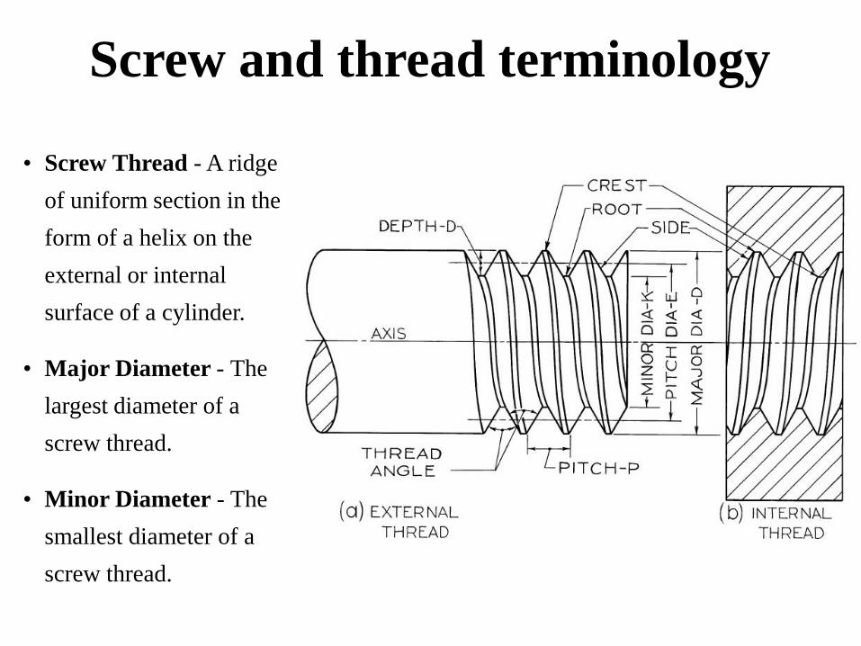
Screw and thread terminology
• Screw Thread - A ridge
of uniform section in the
form of a helix on the
external or internal
surface of a cylinder.
• Major Diameter - The
largest diameter of a
screw thread.
• Minor Diameter - The
smallest diameter of a
screw thread.
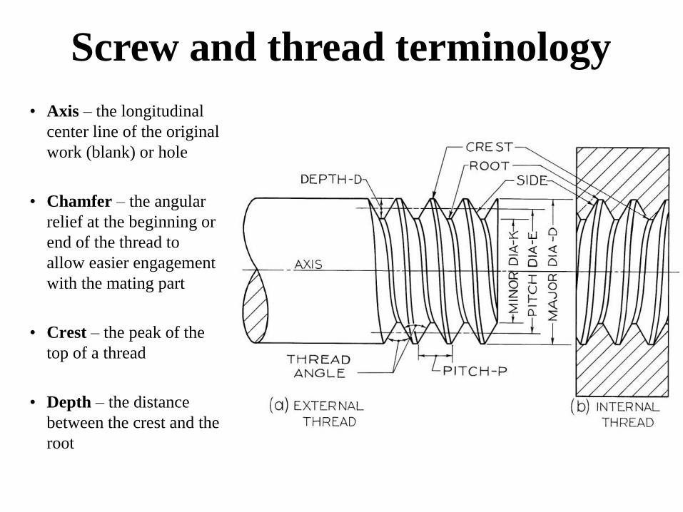
Screw and thread terminology
• Axis – the longitudinal
center line of the original
work (blank) or hole
• Chamfer – the angular
relief at the beginning or
end of the thread to
allow easier engagement
with the mating part
• Crest – the peak of the
top of a thread
• Depth – the distance
between the crest and the
root

• Die – the tool used to perform external threads
• External thread – the screw thread on the outside of a cylindrical surface
• Internal thread – the screw thread on the inside of a cylindrical surface
• Lead – the distance that a screw will travel along the axis when turned by 360°
Screw and thread terminology

• Pitch – the distance
between corresponding
points on adjacent
thread forms, measured
parallel to the axis
expressed in 1 divided
by the number of pitch
in one inch
• Pitch diameter – the
diameter of an
imaginary cylinder that
is located equidistant
between the major and
the minor diameter
Screw and thread terminology
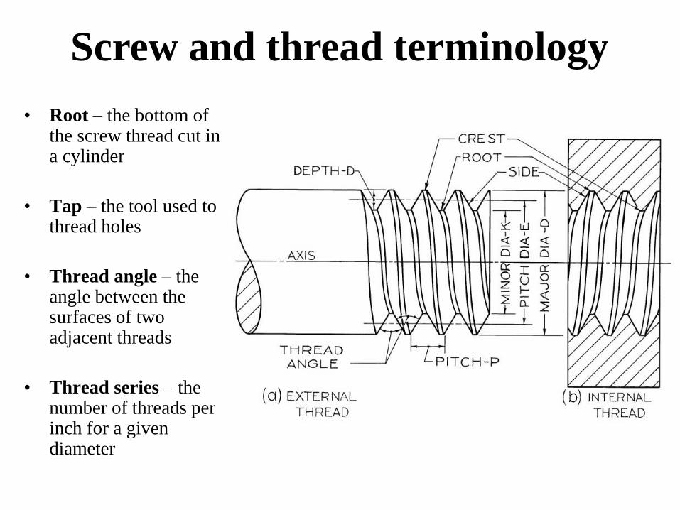
• Root – the bottom of the screw thread cut in a cylinder
• Tap – the tool used to thread holes
• Thread angle – the angle between the surfaces of two adjacent threads
• Thread series – the number of threads per inch for a given diameter
Screw and thread terminology
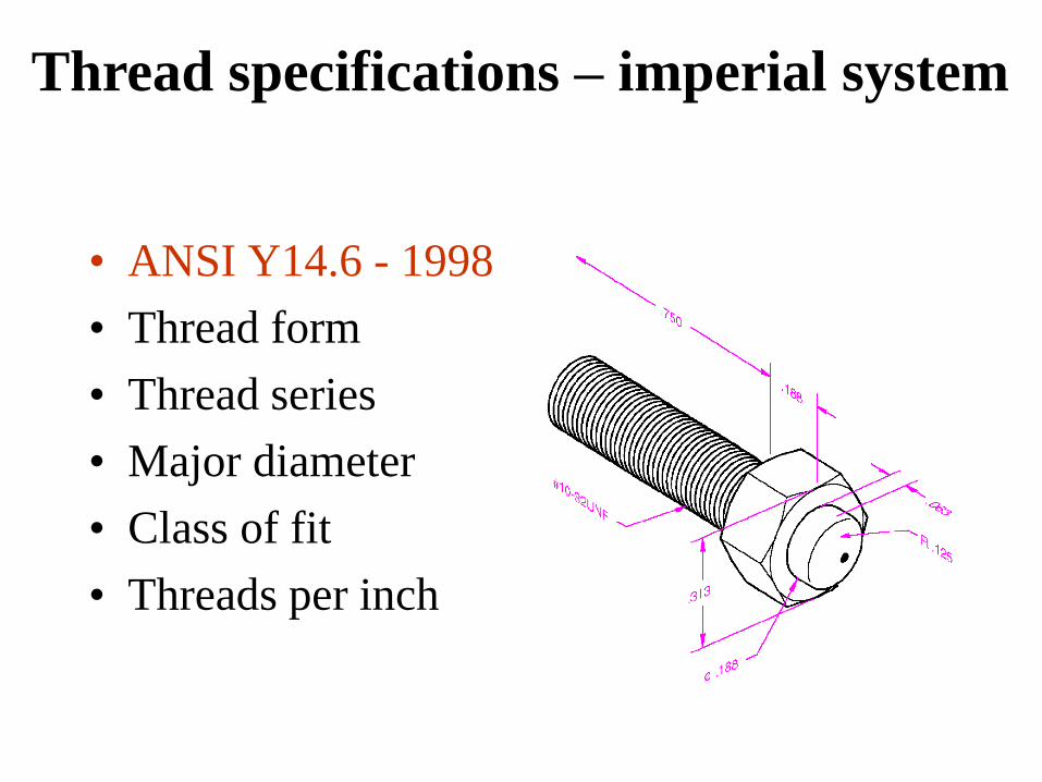
• ANSI Y14.6 - 1998
• Thread form
• Thread series
• Major diameter
• Class of fit
• Threads per inch
Thread specifications – imperial system

Form
• Shows some common thread forms
• Inch & Metric have same proportion
• Sharp V was original american national thread
• American national now has flattened root and crest to increase strength
• Unified thread is agreed as standard in US, Canada and Britain, the crest may be flat or rounded but the root is rounded. Otherwise similar to American national

Form
• ISO Metric is the most common of all the depth is smaller than that of unified national thread
• Knuckle thread is rolled or cast (used in light bulbs and sockets)
• Square and Acme threads are used for transmitting power
• Buttress thread takes pressure on one side ( to the axis)
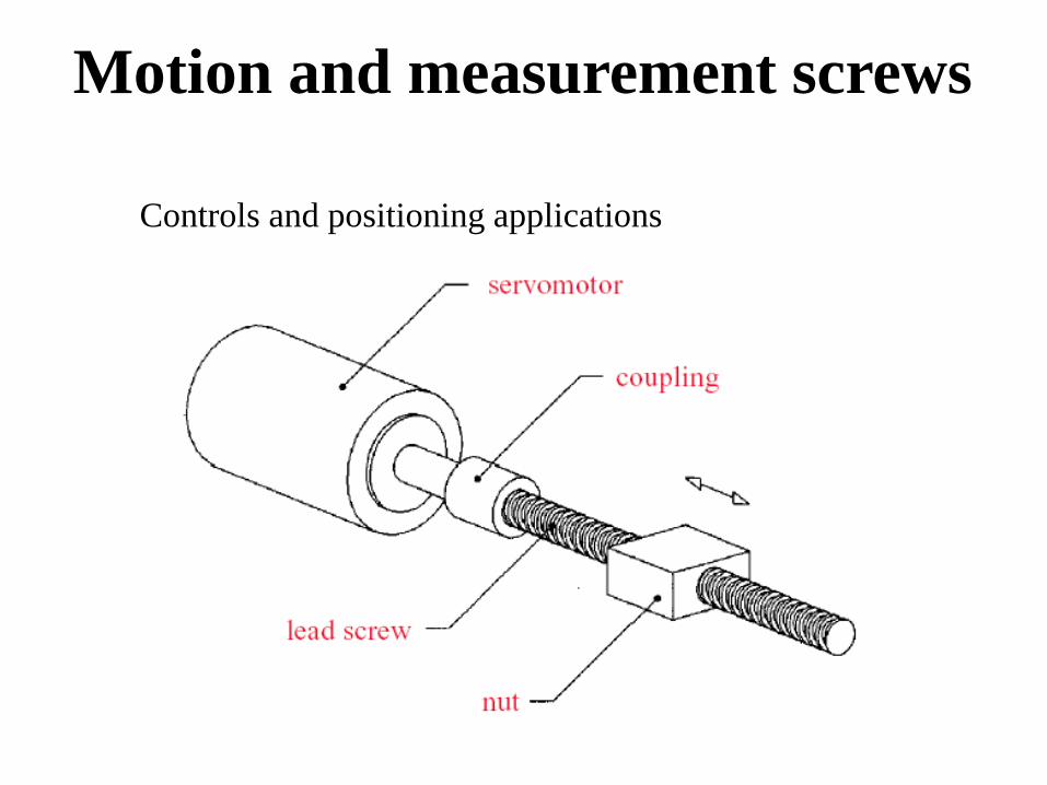
Controls and positioning applications
Motion and measurement screws

Measuring thread pitch
• Pitch is the distance parallel to axis between corresponding points in adjacent thread
• Pitch is measured in millimeters for metric thread and indicated along with the major dia (eg. M10 X 1.5)
• For inch threads, it is mentioned as threads per inch
• Thread Pitch is measured with scale or a thread pitch gage

• Series depends on the pitch and the major dia of the
thread
• Coarse series – used for quick assembly and disassembly
of cast iron, soft metals and plastics (UNC) – Less TPI
• Fine series – used when a great deal of force is necessary
for assembly (UNF) - More TPI
• Extra fine series – used when the length of engagement is
short and the application calls for high degrees of stress
(UNEF) – Lot of TPI
Series

Series
• If it is not stated in the drawing, it is always assumed to be right
hand thread
• A bolt threaded into a tapered hole should be turned clockwise
• Some special cases (where the torque may loosen the fastener)
may require Left hand threads
• If Left hand threads are necessary it is indicated in the drawing
by the letters LH after the thread designation

Number
of starts
of a
thread
Single and multiple thread forms
• If it is not stated in the drawing, it is always assumed to be single thread
• Single thread has a single ridge in the form of helix and lead = pitch
• Multiple threads have 2 or more ridges running side by side • .
• The slope line is the hypotenuse of the right triangle whose short side = .5P
for single thread and p for double and 1.5 P for triple threads
• Multiple threads are required when small rotation must gives faster
movement at low required power (Eg. Toothpaste caps )
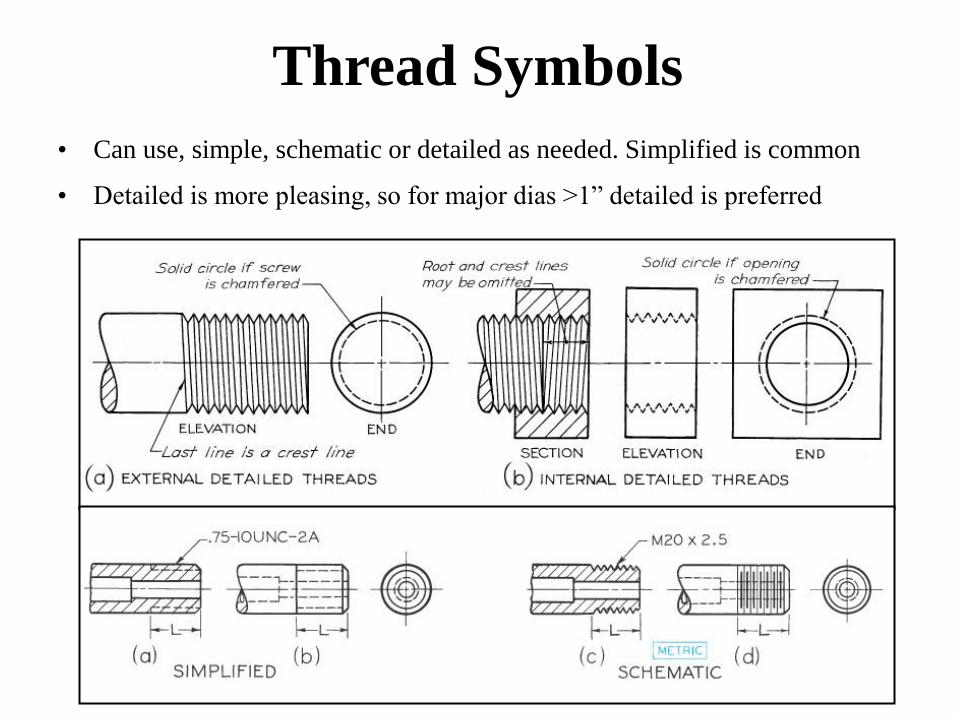
Thread Symbols
• Can use, simple, schematic or detailed as needed. Simplified is common
• Detailed is more pleasing, so for major dias >1” detailed is preferred

Thread Symbols

• Class 1 A an B – a loose fit where quick assembly is
required and play between parts is acceptable
• Class 2 A and B – a high quality general purpose
commercial class of fit for bolts, nuts and screws used in
mass production
• Class 3 A and B – a very high quality threaded fasteners
with a close fit used for precision assembly subjected to
vibrations
• A is for external threads and B is for internal threads
Class of fit

Thread notes

How to represent a thread
• Thread form symbol – M
• Nominal size – in mm
• Pitch size – in mm
• General purpose tolerance – a tolerance
class that includes a tolerance position and a
tolerance grade for both pitch diameter and
minor diameter
ISO representation of threads

Basic metric thread note

Complete threading - metric system
• The number of the tolerance grades
reflects the size of the tolerance
• For example, grade 4 < grade 6 <
grade 8 tolerances
• In addition to the tolerance grade, a
positional tolerance is required
• For external threads:
• Tolerance position e (large allowance)
• Tolerance position g (small allowance)
• Tolerance position h (no allowance)
• For internal threads:
• Tolerance position G (small allowance)
• Tolerance position H (no allowance)
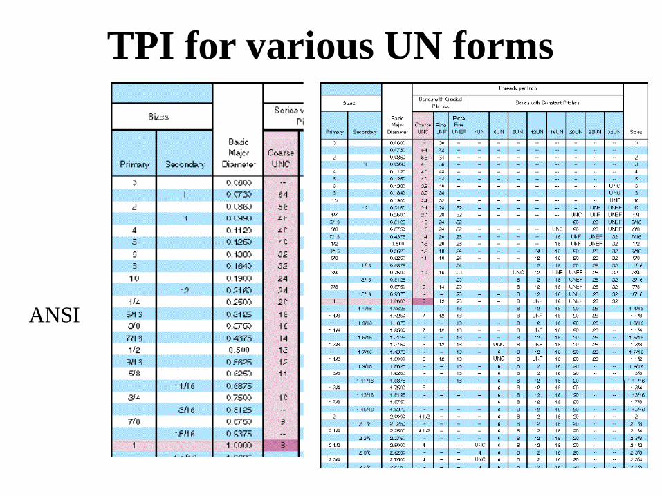
ANSI
TPI for various UN forms

Bolts, nuts and screws

• Large variety of bolts (dimensional, head
shape, etc.)
• Material, quality, finishing
• Grade
Bolts, nuts and screws

• Unfinished bolts are
not machined
anywhere except for
the thread portion
• Finished bolts have
machined face for
washer holding or
flush location on
parts
Bolts, nuts and screws
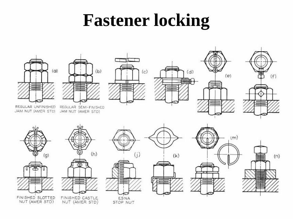
Fastener locking

Castellated nut
Fastener locking
Jam nut Durlock nut

Standard Cap Screws
• 5 different capscrews shown. Socket head can have different shapes of head
and sockets
• Sued in machines to pass through clearance hole to screw into another and
improve appearance
• Socket screws are used while in crowded condition

Standard Cap Screws
• Similar to cap screws but smaller in size.
• General diameters between .06 to .75 inches
• Hex head (not shown here) may be slotted if desired
• Other heads are available as either slotted or recessed
• Generally used for screwing into thin materials

hexsize
heightth_height
Dia"-XXUNY-2A
Part representation

th_heightheight
Dia"-XXUNY-2A
machine screw
Part representation

Assembly representation

Assembly representation

Assembly representation

Assembly representation

Assembly representation

Assembly representation

• Clips, rings, pins, etc.
Other non-permanent fasteners

Other non-permanent fasteners
• Clips, rings, pins, etc.

• Once assembled, the parts of the assembly (including the
fastener) would be destroyed to disassemble the assembly.
• Rivets, soldering, brazing, welding
Permanent fasteners

• Used to permanently fasten mechanical
components
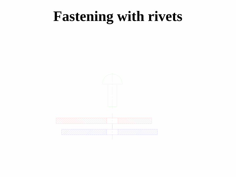
Rivets

Riveting process

The headless end of the rivet is plastically deformed such
that keeps together two components
Fastening with rivets

Fastening with rivets
Fastening with rivets

Fastening with rivets

Fastening with rivets

Fastening with rivets

Fastening with rivets
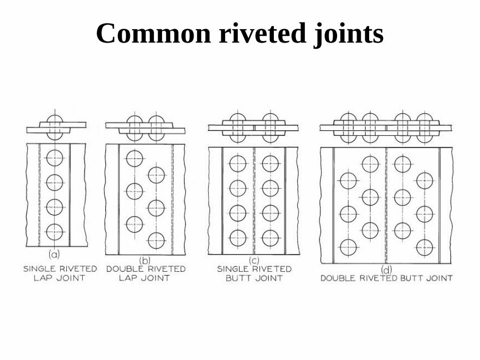
Common riveted joints

Self piercing rivets
Blind rivets

• Joining of two part using a third component –
filler that joins the parts when in liquid state
• Soldering and brazing – low temperature binding
materials – Sn-Pb, Cu-Ag alloys
• Limited capability to face thermo-mechanical
loading
Soldering, brazing, welding

• Very well regulated activity
• It requires license to practice
• Welders bear significant responsibility
• The activity is based on rigorous rules and regulations
• Designer prescribe welding based on mechanics of
materials calculations
• Symbols indicate the type of welding
Welding
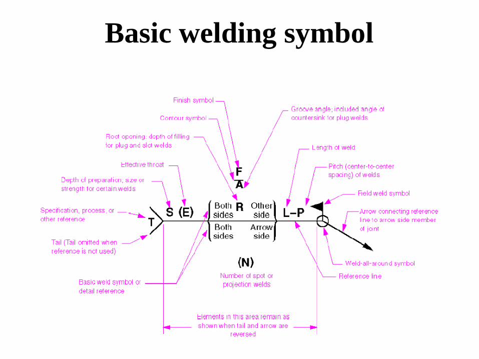
Basic welding symbol

Basic welding symbols

Basic welding symbols
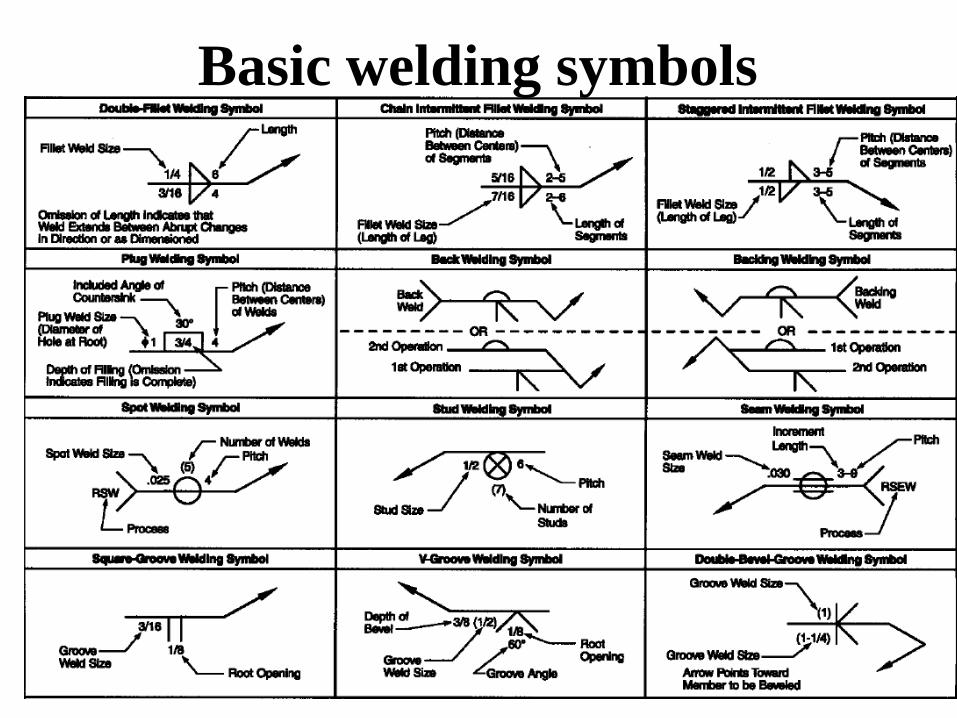
Basic welding symbols

• Designed to store energy when
deflected and return the same
amount of energy when released
• Basically divided as Helical and Flat
springs
• Helical springs are sub divided as
– Compression Springs
– Extension Springs
– Torsion Springs
Springs

Helical Springs
Compression, Extension & Torsion

Working drawing of a compression spring
Spring representation
Detailed representation
Sch
emat
ic r
epre
sen
tati
on
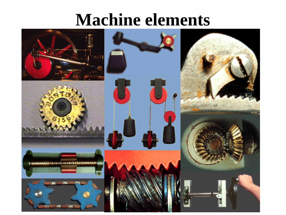
Machine elements

• Used to transmit power or support elements
that transmit power
• Gears, belts/pulleys, chain/sprockets,
cams/followers
• Shafts, bearings
• Springs, ratchets, clutches, brakes
Machine elements

Gear and pinion mechanisms – power transmission
Between two close-positioned shafts
Gears
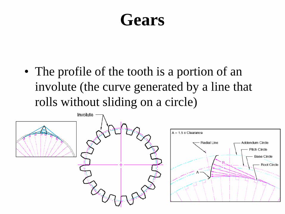
• The profile of the tooth is a portion of an
involute (the curve generated by a line that
rolls without sliding on a circle)
Gears

• Meshing
require the
same geometry
of the teeth
• The rule of
meshing – the
transmission
ratio i
Gears

Gears

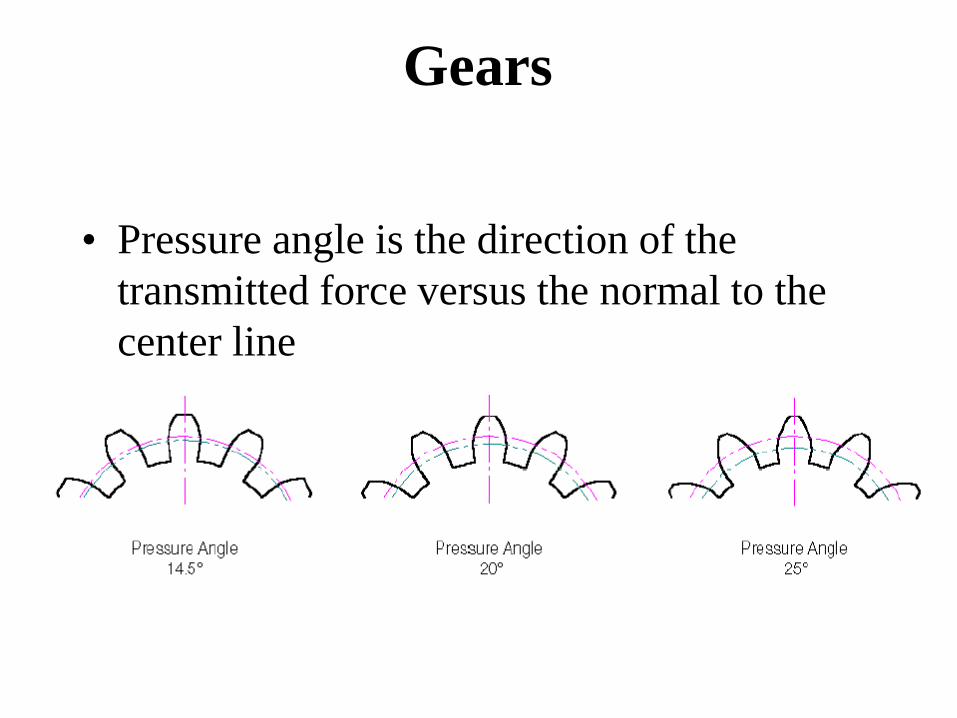
• Pressure angle is the direction of the
transmitted force versus the normal to the
center line
Gears
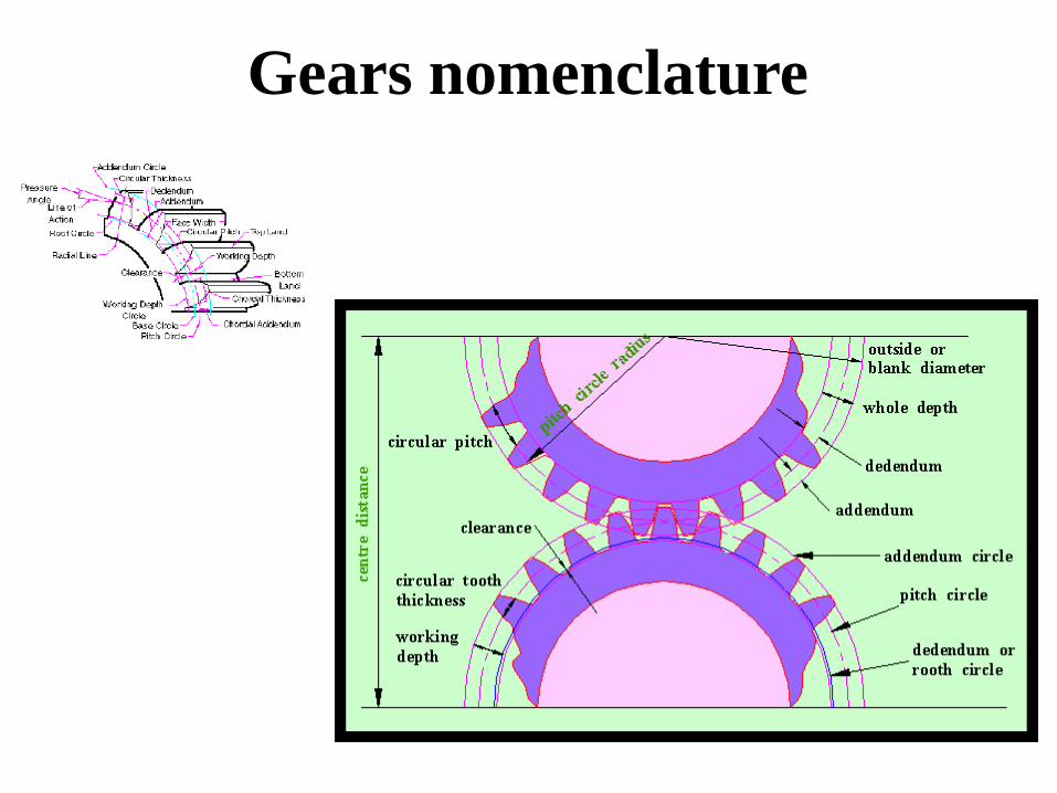
Gears nomenclature
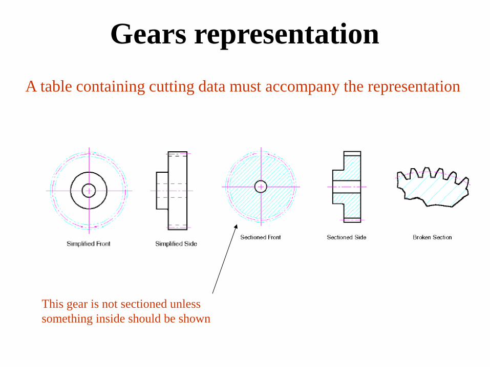
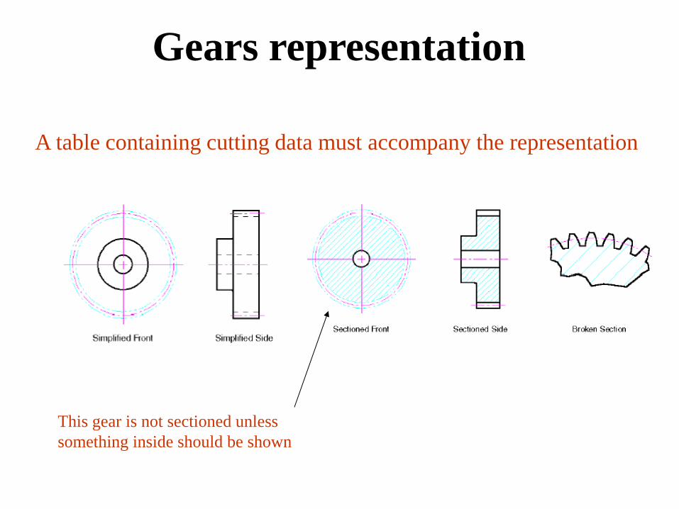
This gear is not sectioned unless
something inside should be shown
A table containing cutting data must accompany the representation
Gears representation

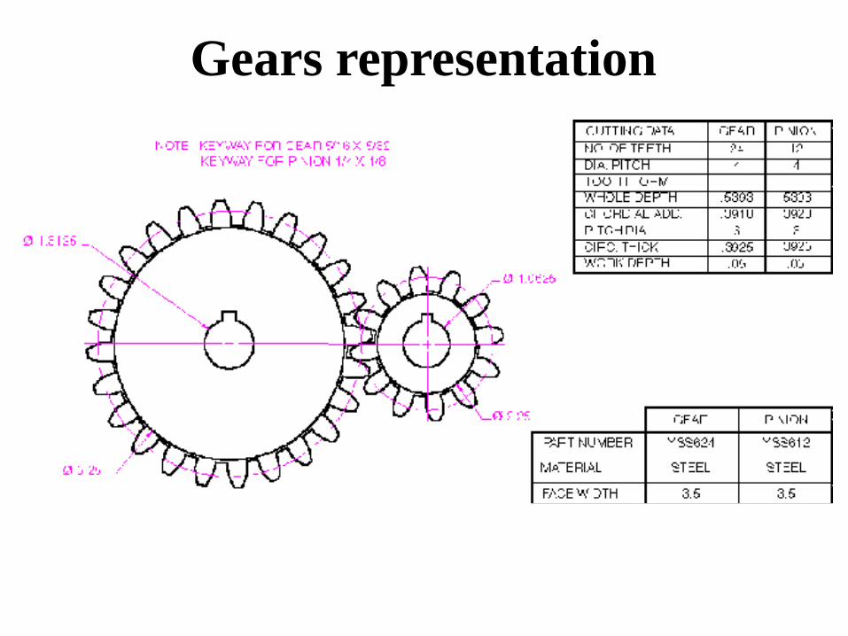
Gears representation
A table containing cutting data must accompany the representation
Gears representation
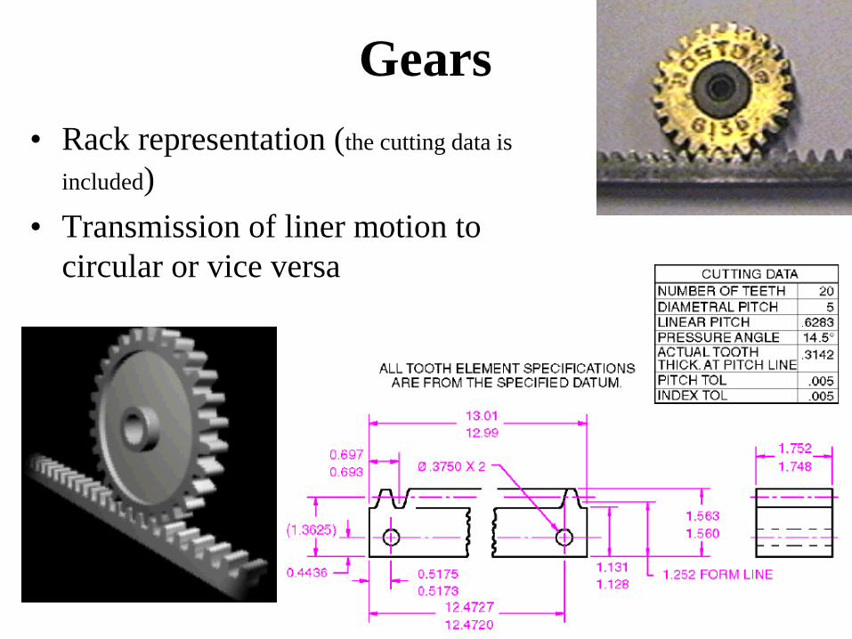
Gears
• Rack representation (the cutting data is
included)
• Transmission of liner motion to
circular or vice versa

Worm and gear
• Worm and Gear representation
• Transmission of motion between
out of plane, perpendicular axes
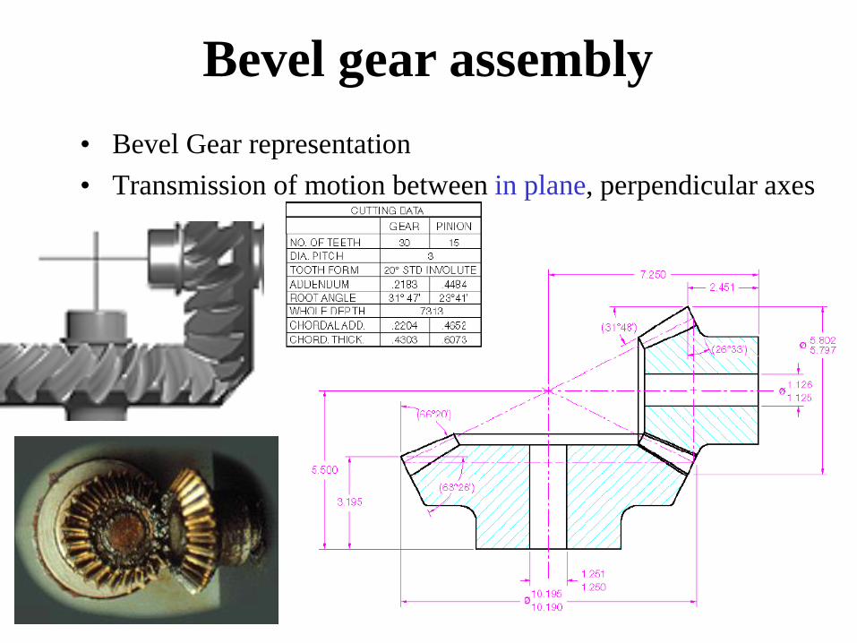
Bevel gear assembly
• Bevel Gear representation
• Transmission of motion between in plane, perpendicular axes

Gears
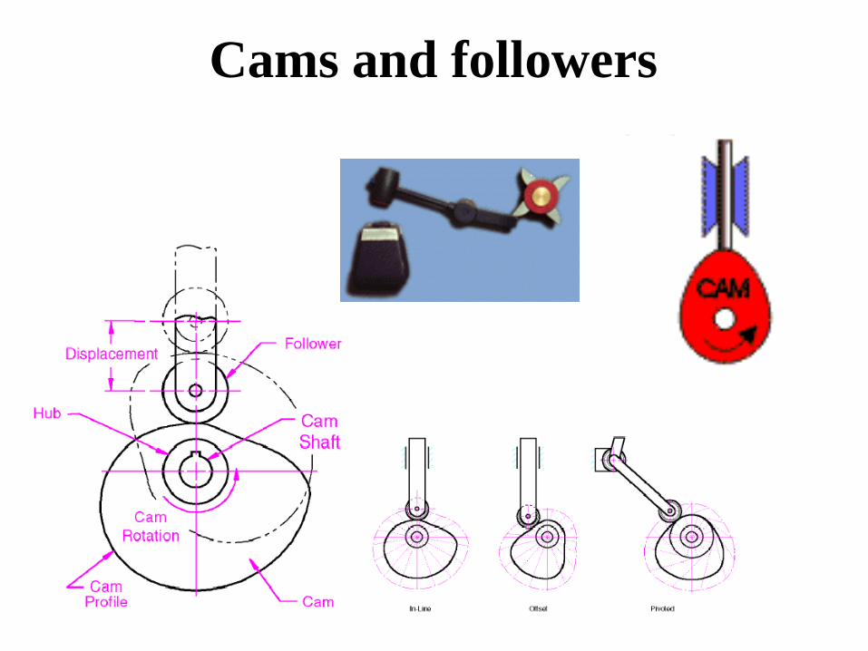
Cams and followers
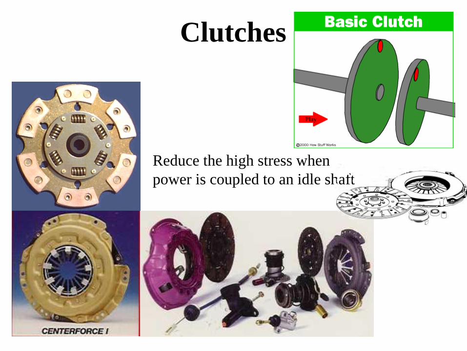
Reduce the high stress when
power is coupled to an idle shaft
Clutches

Bearings

Ball and roller bearings

Ball and roller bearings

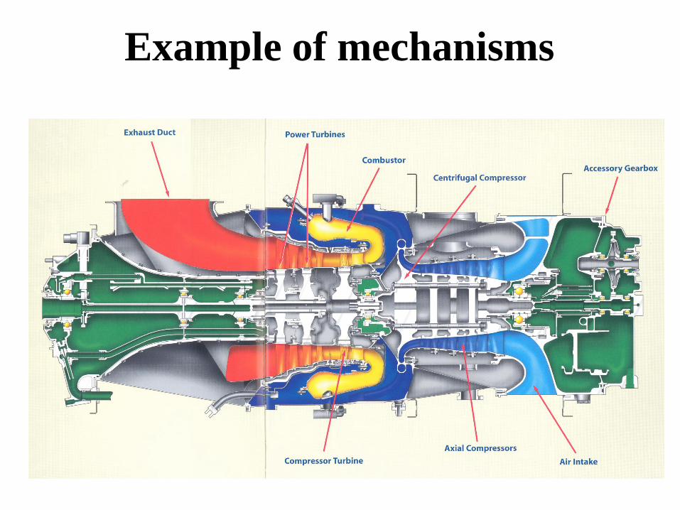
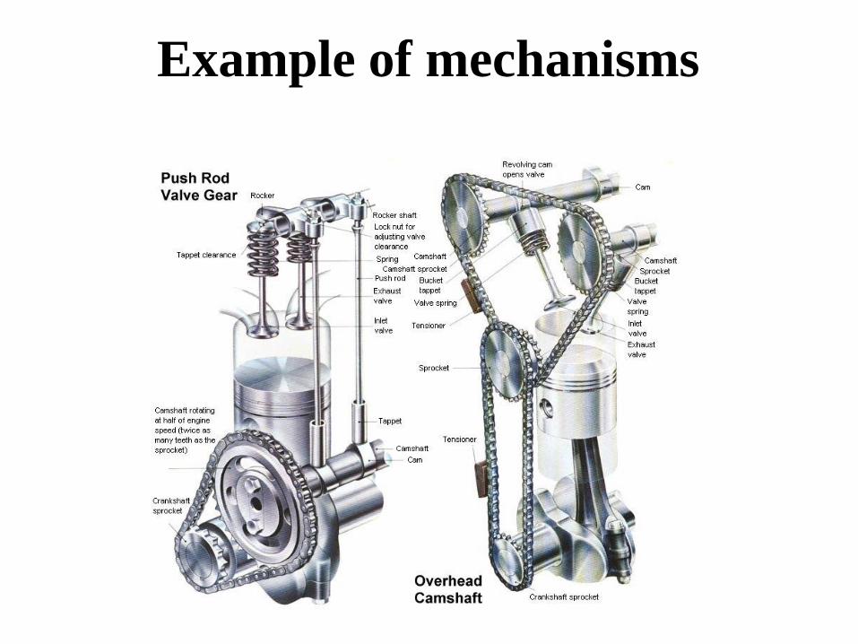
Example of mechanisms

Example of mechanisms

Example of mechanisms

Example of mechanisms
Example of mechanisms

Machine elements

• Used to transmit power or support elements
that transmit power
• Gears, belts/pulleys, chain/sprockets,
cams/followers
• Shafts, bearings
• Springs, ratchets, clutches, brakes
Machine elements

Gear and pinion mechanisms – power transmission
Between two close-positioned shafts
Gears

• The profile of the tooth is a portion of an
involute (the curve generated by a line that
rolls without sliding on a circle)
Gears

• Meshing
require the
same geometry
of the teeth
• The rule of
meshing – the
transmission
ratio i
Gears
• Pressure angle is the direction of the
transmitted force versus the normal to the
center line
Gears

Gears nomenclature
This gear is not sectioned unless
something inside should be shown
A table containing cutting data must accompany the representation
Gears representation

Gears representation

Gears representation

• Rack representation (the cutting data is included)
Gears

Worm and gear

Bevel gear assembly

Gears
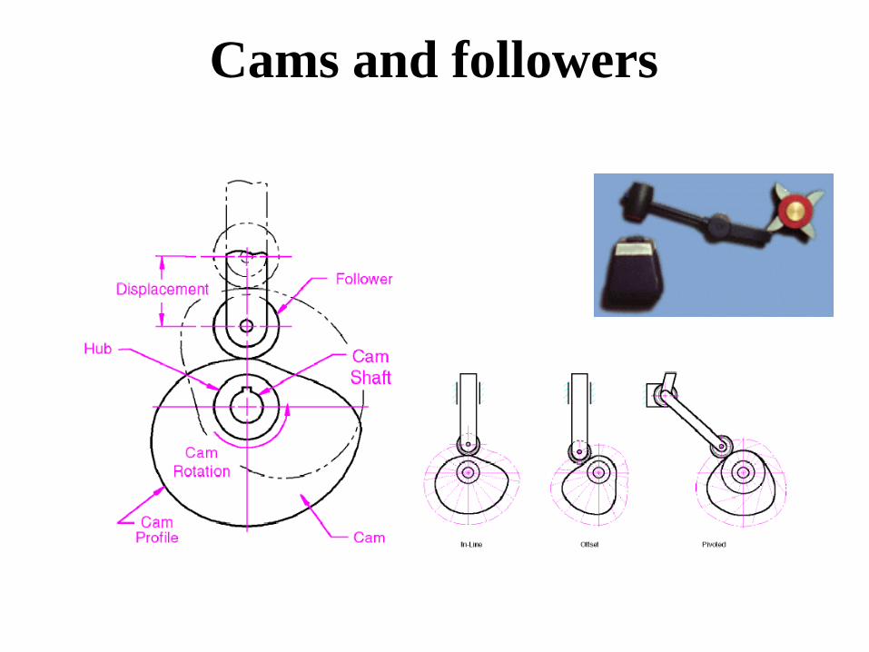
Cams and followers

Roller-type followers stud and bore
Cams

Reduce the high stress when
power is coupled to an idle shaft
Clutches

Bearings

Ball and roller bearings

Ball and roller bearings


• One working drawing is made for each non-standard component
• All the necessary information to carry out manufacturing must be contained within the drawing
• Recommendation: use a reference (textbook) when draw a working drawing
• Assembly working drawing contain the necessary information to perform the assembly of the system
Working drawings

Working drawings


Working drawings

Working drawings
Example of mechanisms

Example of mechanisms

Example of mechanisms

Example of mechanisms

Example of mechanisms