lec4.pptx.pdf
DESCRIPTION
control 4TRANSCRIPT
10/16/2013
Barkhordari 1
DIGITAL CONTROL
SYSTEMS Modeling of Digital Control Systems
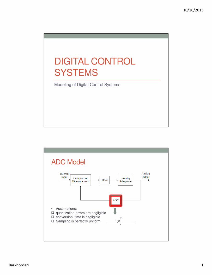
ADC Model
• Assumptions:
� quantization errors are negligible
� conversion time is negligible
� Sampling is perfectly uniform

10/16/2013
Barkhordari 2
DAC Model
• Assumptions:
�DAC outputs are exactly equal in magnitude to their inputs.
�The DAC yields an analog output instantaneously.
�DAC outputs are constant over each sampling period.
• The input-output relationship of the DAC
The Transfer Function of the ZOH
• The transfer function of the ZOH is
10/16/2013
Barkhordari 3
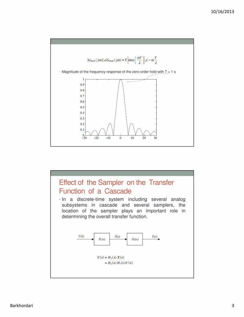
• Magnitude of the frequency response of the zero-order hold with T = 1 s
Effect of the Sampler on the Transfer
Function of a Cascade • In a discrete-time system including several analog
subsystems in cascade and several samplers, the
location of the sampler plays an important role in
determining the overall transfer function.

10/16/2013
Barkhordari 4
• Inverse Laplace transforming gives the time response
• The equivalent impulse response for the cascade is given
by the convolution of the cascaded impulse responses.
• Cascading results in a new form for the impulse
response. So if the output of the system is sampled to
obtain
it is not possible to separate the three time functions
that are convolved to produce it.
• For n blocks not separated by samplers:

10/16/2013
Barkhordari 5
• For a linear time-invariant (LTI) system with impulse-
sampled input, the output is given by
• Changing the order of summation and integration gives
• Sampling the output yields the convolution summation
• if the cascade is separated by samplers, then each block
has a sampled output and input as well as a z-domain
transfer function.
• For n blocks separated by samplers:

10/16/2013
Barkhordari 6
• Find the equivalent sampled impulse response sequence and
the equivalent z-transfer function for the cascade of the two analog
systems with sampled input
1. If the systems are directly connected.
2. If the systems are separated by a sampler.
• 1
• 2

10/16/2013
Barkhordari 7
DAC, Analog Subsystem, and ADC
Combination Transfer Function
• Because both the input and the output of the cascade are sampled, it is possible to obtain its z-domain transfer function in terms of the transfer functions of the individual subsystems.
• The transfer function of the DAC and analog subsystem
cascad:
• The corresponding impulse response
• The sampled impulse response

10/16/2013
Barkhordari 8
• z-transfer function of the DAC (zero-order hold), analog
subsystem, and ADC (ideal sampler) cascade:
• Find GZAS(z) for the cruise control system for the vehicle shown in
Figure, where u is the input force, v is the velocity of the car, and b is
the viscous friction coefficient.
10/16/2013
Barkhordari 9
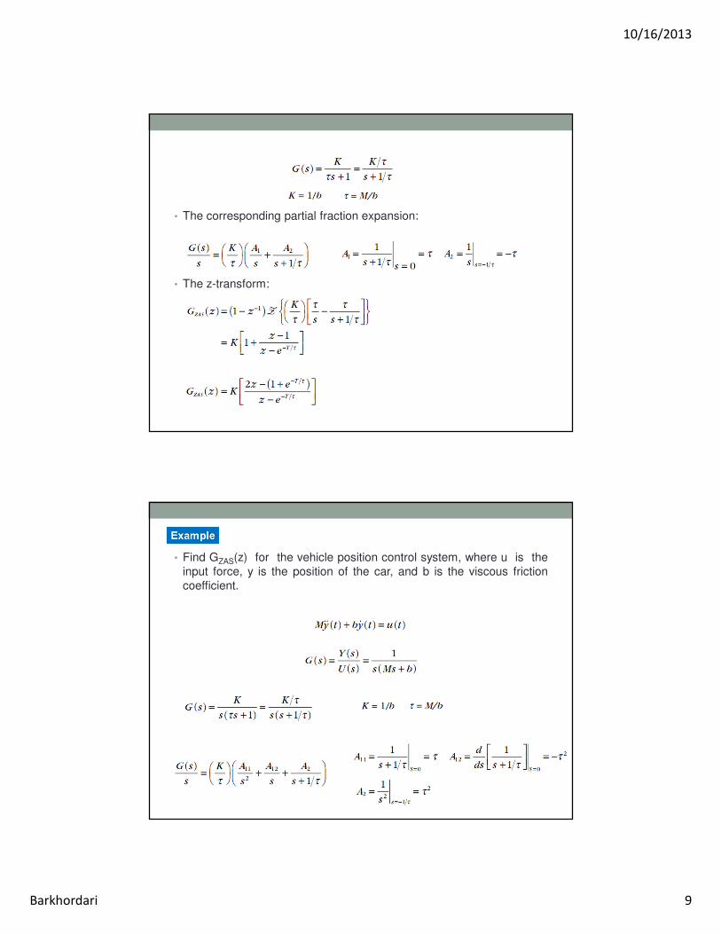
• The corresponding partial fraction expansion:
• The z-transform:
• Find GZAS(z) for the vehicle position control system, where u is the
input force, y is the position of the car, and b is the viscous friction
coefficient.

10/16/2013
Barkhordari 10
The Closed-loop Transfer Function
• The closed-loop transfer function for the system:
The closed-loop characteristic equation:

10/16/2013
Barkhordari 11
• Find the Laplace transform of the analog and sampled output
for the block diagram
• which involves three multiplications in the s-domain. In the time
domain, x(t) is obtained after three convolutions.
• Thus, the impulse-sampled variable has the Laplace transform

10/16/2013
Barkhordari 12
• Thus, the sampled output is
• With the transformation

10/16/2013
Barkhordari 13
Analog Disturbances in a Digital
System • Disturbances are variables that are not included in the
system model but affect its response.

10/16/2013
Barkhordari 14
Steady-state Error and Error Constants
• standard inputs: sampled step, sampled ramp, sampled
parabolic
• The tracking error:

10/16/2013
Barkhordari 15
• Applying the final value theorem yields the steady-state
error:
• The limit exists if all (z − 1) terms in the denominator cancel. This
depends on the reference input as well as on the loop gain.
• rewrite the loop gain in the form
• where N(z) and D(z) are numerator and denominator polynomials,
respectively, with no unity roots.
• Definition type Number. The type number of the
system is the number of unity poles in the system z-
transfer function.
• Note that s-domain poles at zero play the same role as z-
domain poles at 1.

10/16/2013
Barkhordari 16
• steady-state error for sampled step input
• Or
• the steady-state error for a sampled unit step input:
position error constant
• steady-state error for sampled ramp input
• the steady-state error for a sampled unit ramp input:
velocity error constant

10/16/2013
Barkhordari 17
• Find the steady-state position error for the digital position control
system with unity feedback and with the transfer functions
1. For a sampled unit step input.
2. For a sampled unit ramp input.
The loop gain of the system is given by
it has zero steady-state error for a sampled step input and a finite
steady-state error for a sampled ramp input given by
• Find the steady-state error for the analog system
1. For proportional analog control with a unit step input.
2. For proportional digital control with a sampled unit step input.
the position error constant for analog control is K/a, and the steady-
state error is
• the DAC-plant-ADC z- transfer function
• the position error constant for digital control is
• and the associated steady-state error is the same as that of the
analog system with proportional control.

10/16/2013
Barkhordari 18
MATLAB commands
• For a system with a zero-order hold and sampler (DAC and ADC),
we use
• For a first-order hold, we use