learning objectivesaucache.autodesk.com/.../v1_ma3060_bullock.docx · web viewthis class will help...
TRANSCRIPT
Complete Plastic Part Design in Autodesk® Inventor®
MA3060
Ryan Bullock / Lantronix
This class will help you design parts that will be made from an injection molding process. Autodesk Inventor has some very powerful tools that greatly assist the design of plastic parts, and these tools will be covered in this class. We will provide design rules and suggestions, including draft angles, wall thickness, surface textures, etc. We will also help you pick the plastic material to use for your application. We will focus on practical applications and real-life examples.
Learning ObjectivesAt the end of this class, you will be able to:
Use Inventor to design plastic injection molded parts
Select materials appropriate for your design
Select a finish appropriate for your material
About the SpeakerRyan is an electro-mechanical engineer based in Irvine, California. For the last 15 years, he has used Autodesk® products, including AutoCAD®, AutoCAD Mechanical, and Autodesk Inventor® to design consumer electronics. Ryan has been attending Autodesk University since 2004. He is responsible for the design of at least two new products per month, and brings his practical knowledge of materials and design techniques to Autodesk University.
What is injection molding?Injection molding is an ideal way to mass produce plastic parts with accuracy, precision and repeatability. Injection molding is a process of taking liquefied plastic, pushing into a mold where it takes the shape of the cavity of the mold and solidifies while cooling.
Material SelectionThere are many types of plastic that can be used for injection molding, virtually all thermoplastics are able to be used in the injection molding process. Some common examples are:
ABS – Acrylonitrile Butadiene Styrene – rigid tough, stablePA – Polyamides – Rigid, hard-wearing, resistant to solvents, can be steam sterilizedPC – Polycarbonate – Rigid, outstanding impact, UV and flame resistance, stable, PMMA – Acrylic – clear, glossy, rigid, weather resistant.EVA – Ethylene Vinyl Acetate – flexible, high friction coefficientPVC – Polyvinyl Chloride – Rigid or flexible, durable, weatherproof, electrical insulation
For more information, check these helpful resources:

Complete Plastic Part Design in Autodesk Inventor
www.matweb.comhttp://www.protomold.com/DesignTips.aspxPlastics 2 – Materials for Inspirational Design by Chris LefteriIndustrial Design – Material and Manufacturing guide – Jim Lesko
Texture SelectionFor cosmetic reasons, the mold can be textured or polished smooth. Depending on the material type and look desire, different textures or levels of polish can be used.
Textured plastic helps hide imperfections and require a larger draft angle for a deeper texture. Yick Sang and Mold Tech have specifications for texture types and draft angles required.
Polished surfaces are also common in modern plastic parts. Surfaces that are to have polished surfaces should be made from materials with better scratch resistance such as polycarbonate.
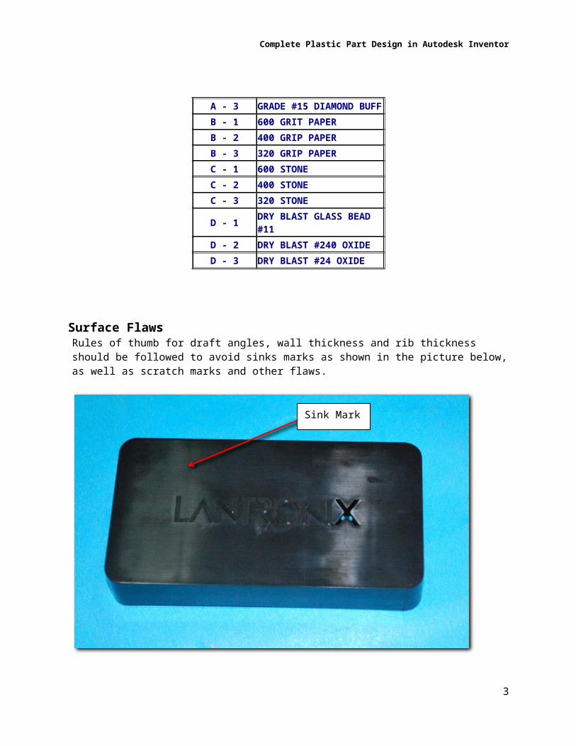
SPI FINISH GUIDE
A - 1 GRADE #3 DIAMOND BUFF
A - 2 GRADE #6 DIAMOND BUFF
A - 3 GRADE #15 DIAMOND BUFF
B - 1 600 GRIT PAPERB - 2 400 GRIP PAPERB - 3 320 GRIP PAPERC - 1 600 STONEC - 2 400 STONEC - 3 320 STONE
D - 1 DRY BLAST GLASS BEAD #11
D - 2 DRY BLAST #240 OXIDE
D - 3 DRY BLAST #24 OXIDE
Surface FlawsRules of thumb for draft angles, wall thickness and rib thickness should be followed to avoid sinks marks as shown in the picture below, as well as scratch marks and other flaws.
2
Complete Plastic Part Design in Autodesk Inventor
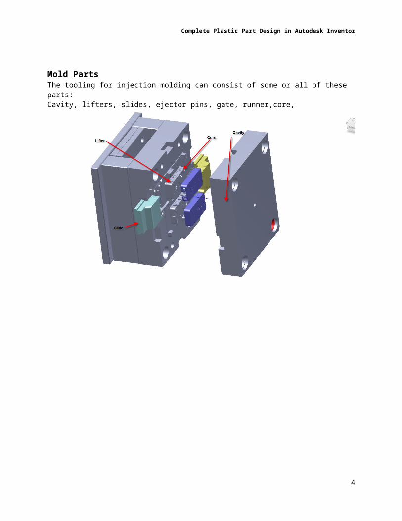
Mold PartsThe tooling for injection molding can consist of some or all of these parts: Cavity, lifters, slides, ejector pins, gate, runner,core,
3
Sink Mark
Complete Plastic Part Design in Autodesk Inventor
Other terminology:Core- side of the tool where the plastic part will stick to and is ejected fromCavity- upper half of the injection mold usually the show surface of the finished productLifter- used to create undercuts that cannot be accessed from the outsideSlide- Portion of Custom plastic injection molds that is used for creating undercuts that can be accessed from outside the partDirection of pull- the axis that the cavity and core separate onShrinkage- how much the plastic material will shrink after cooledUndercut- feature that cannot be created by the cavity nor core because other features are in the wayDraft Angle – angle of the taper on the part / tooling
Sample 1 – Print Server EnclosureThis Enclosure is an example that uses snap features, ribs, and a variety of textures to house 2 PCBs.
Start Design by creating geometry to define the shape of the product.
As soon as possible, start considering draft angles. They will be much more difficult to solve when your geometry gets too complex. All features should have draft. Recommend to set a user parameter for draft angle so all draft angles can be adjusted with one operation.
4

Complete Plastic Part Design in Autodesk Inventor
Draft
Once the shape is defined, shell the part with a wall thickness appropriate for your material. This wall thickness is another good place to make use of a user parameter.
Shell
5

Complete Plastic Part Design in Autodesk Inventor
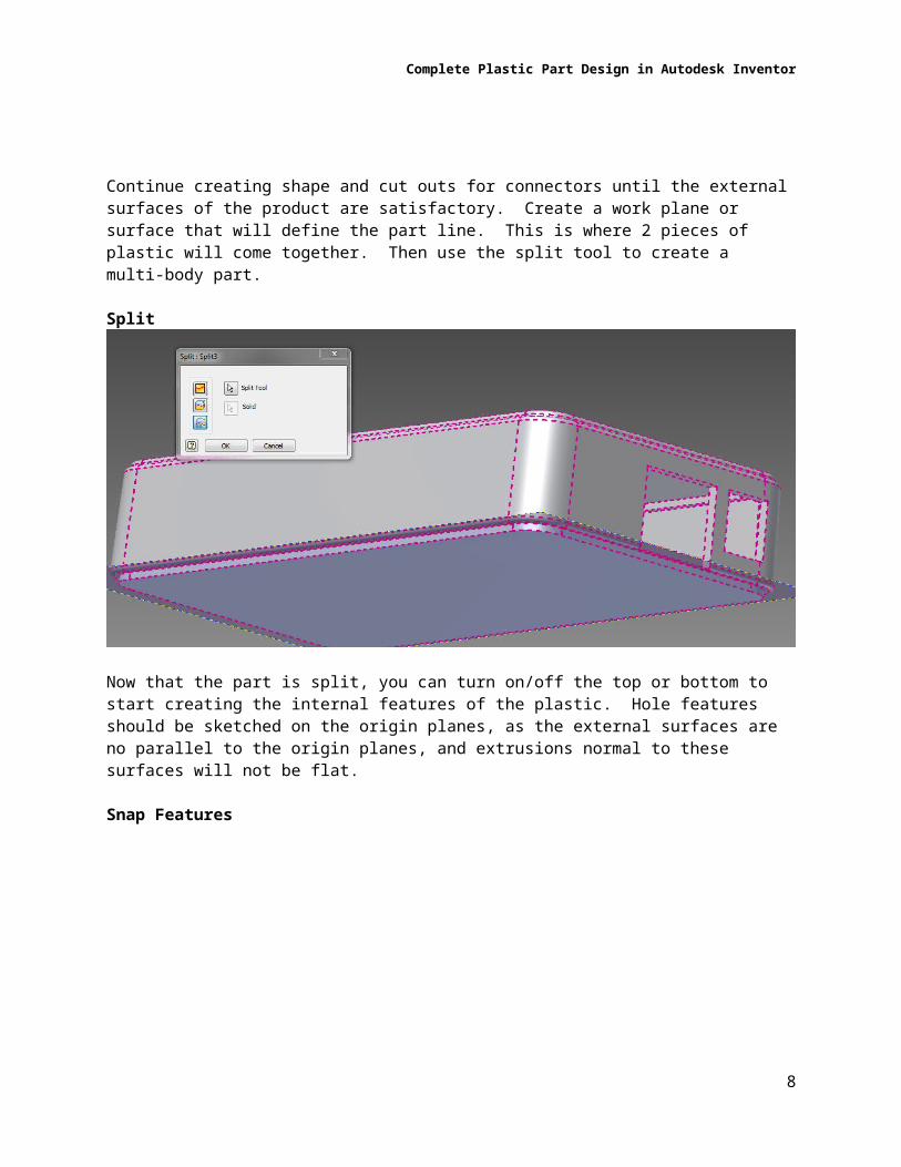
Continue creating shape and cut outs for connectors until the external surfaces of the product are satisfactory. Create a work plane or surface that will define the part line. This is where 2 pieces of plastic will come together. Then use the split tool to create a multi-body part.
Split
Now that the part is split, you can turn on/off the top or bottom to start creating the internal features of the plastic. Hole features should be sketched on the origin planes, as the external surfaces are no parallel to the origin planes, and extrusions normal to these surfaces will not be flat.
Snap Features
6

Complete Plastic Part Design in Autodesk Inventor
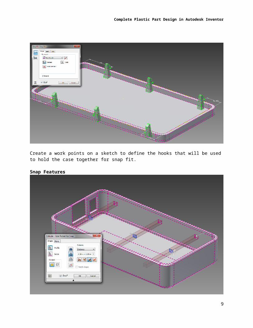
Create a work points on a sketch to define the hooks that will be used to hold the case together for snap fit.
Snap Features
Create a sketch on the origin work plane, and reference the hooks to create pockets in the top part to complete the snap fit features. Be careful not to make the wall thickness too thin. Depending on the material type, you do not want to go less than 0.025” wall thickness.
7
Complete Plastic Part Design in Autodesk Inventor
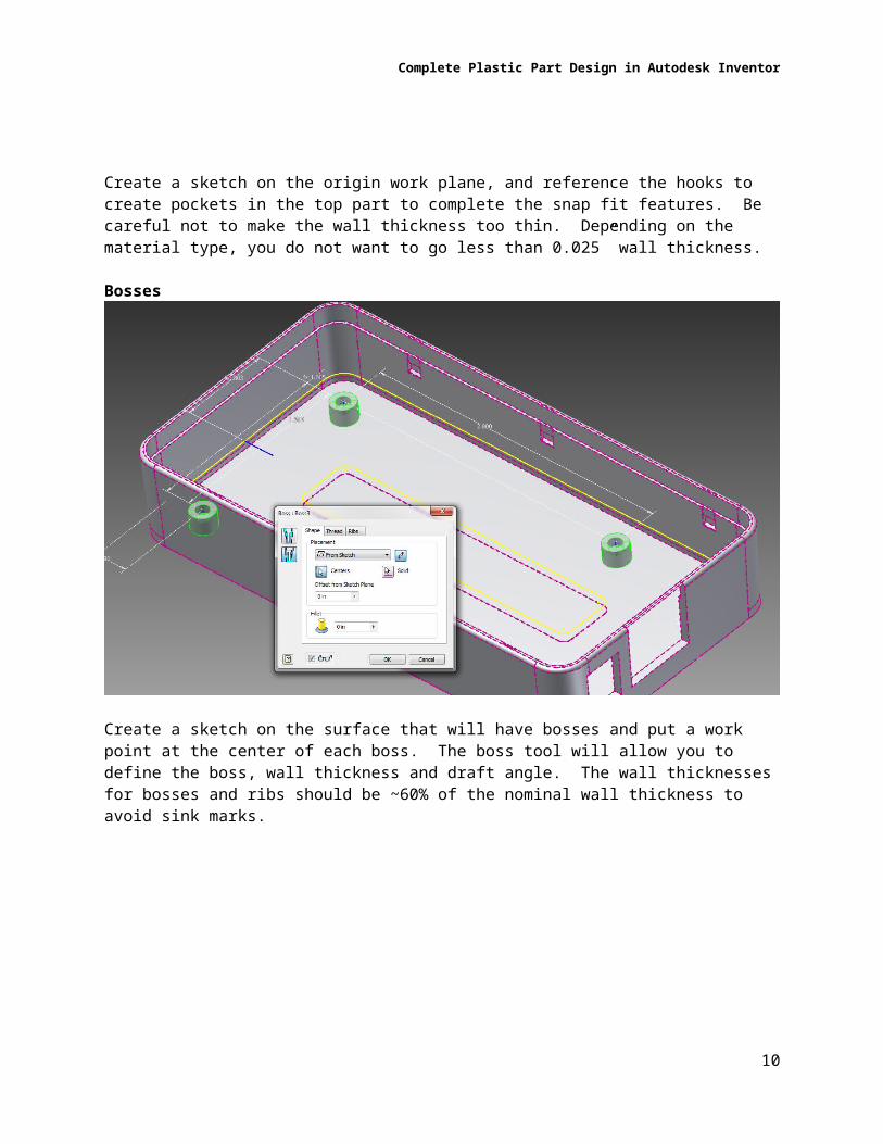
Bosses
Create a sketch on the surface that will have bosses and put a work point at the center of each boss. The boss tool will allow you to define the boss, wall thickness and draft angle. The wall thicknesses for bosses and ribs should be ~60% of the nominal wall thickness to avoid sink marks.
8
Complete Plastic Part Design in Autodesk Inventor
Ribs
Create a line to represent the center of the rib. The rib thickness should be ~.6 of the wall thickness with the same draft angle as the other features. The height of the rib should not be more than 5x that wall thickness. In addition to add strength to the part, ribs help plastic flow through the cavity.
9
Complete Plastic Part Design in Autodesk Inventor
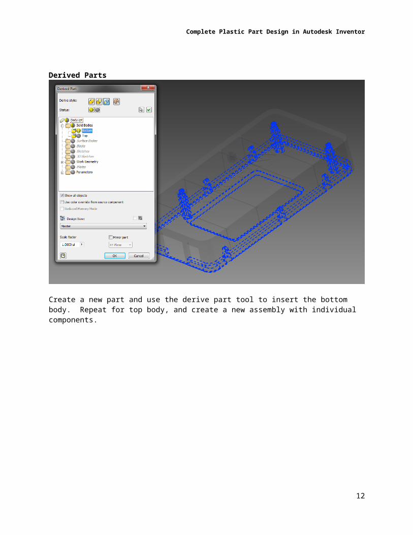
Derived Parts
Create a new part and use the derive part tool to insert the bottom body. Repeat for top body, and create a new assembly with individual components.
10

Complete Plastic Part Design in Autodesk Inventor
Analysis
Use the draft analysis tool to make sure all of the features have draft angle to ensure the part will come out of the mold.
Cross Section Analysis
Use the cross section analysis to ensure walls are not too thin nor too thick
11
Complete Plastic Part Design in Autodesk Inventor
Heading 4 (section sub-heading)
12