learning objectives - nemes home pageneme-s.org/cthss/machining fundamentals/mfim13.pdf · research...
TRANSCRIPT
INSTRUCTIONAL MATERIALSText: pages 201–240
Test Your Knowledge Questions, pages 239–240
Workbook: pages 69–76Instructor’s Resource: pages 171–190
Guide for Lesson PlanningResearch and Development IdeasReproducible Masters:
13-1 Lathe Operation13-2 Lathe Measurement13-3 Parts of a Lathe13-4 High-Speed Steel Cutting Tools
(nomenclature and shapes)13-5 Sharpening HSS Cutter Bits13-6 Using the Cutter Bit Gage13-7 Calculating Cutting Speeds13-8 Cutting Speed and Feed Problems13-9 A, Checking Center Alignment13-9 B, Checking Center Alignment13-10 Facing in a Chuck13-11 Test Your Knowledge Questions
Color Transparencies (Binder/CD only)
GUIDE FOR LESSON PLANNINGBecause this chapter is rather extensive, it
should be divided into several segments. Teachthe segments that best suit your program.
Part I—Parts of the LatheHave students read and study pages
201–211. Review the assignment using Repro-ducible Masters 13-1, 13-2, and 13-3 as overheadtransparencies and/or handouts. Discuss thefollowing:
• How a lathe operates.• How lathe size is determined.• Major parts of the lathe.• Preparing a lathe for operation.• Cleaning a lathe.• Lathe safety.• Emphasize the importance of lubricating
and checking over a lathe beforeoperating.
Part II—Cutting Tools and Tool HoldersA selection of cutting tools and tool holders
should be available for the class to examine.Have students read and study pages
211–219. Review the assignment using Repro-ducible Masters 13-4, 13-5, and 13-6 as overheadtransparencies and/or handouts. Discuss thefollowing:
• High-speed steel (HSS) cutting tools andhow they are shaped for different types ofturning.
Chapter 13
The Lathe
LEARNING OBJECTIVESAfter studying this chapter, students will be able to:� Describe how a lathe operates.� Identify the various parts of a lathe.� Safely set up and operate a lathe using various work-holding devices.� Sharpen lathe cutting tools.
171

• How to sharpen high-speed steel cuttingtools.
• Carbide-tipped cutting tools.• Indexable insert cutting tools.• How the shape of an insert determines its
strength.• The reason for a chip breaker on a single
point tool.• The nine basic categories of cutting tools.• Emphasize how to handle sharpened cut-
ting tools to prevent injury and prematuredulling.
Part III—Cutting Speeds and FeedsHave students read and study pages 220–222.
Review the assignment using ReproducibleMaster 13-7 as an overhead transparency and/orhandout. Discuss the following:
• The factors that effect cutting speeds andfeeds.
• How to calculate cutting speeds andfeeds. Use Reproducible Master 13-8 toprovide practice in calculating cuttingspeeds and feeds.
• How lathe speed and carriage feed is seton the lathes in your shop/lab.
• Reason for making roughening and fin-ishing cuts.
• How depth of cut is determined on lathesin your shop/lab.
• Demonstrate the difference betweenroughing cuts and finishing cuts. All stu-dents must wear approved eye protectionduring the demonstration.
Part IV—Work-Holding AttachmentsSeveral lathes should be set up to show
work mounted between centers, mounted invarious types of chucks and collets, and boltedto a faceplate.
Have students read and study page 222.Discuss and demonstrate the various workholding attachments set up on the lathes.Explain the safety precautions that must beobserved when mounting the attachments onthe lathe and when they are being used.
Part V—Turning Between CentersHave a lathe set up for turning between cen-
ters plus a selection of the equipment necessaryfor turning between centers.
Students should read and study pages223–231. Review the assignment using Repro-ducible Masters 13-9 A and B as overhead trans-parencies and/or handouts. Demonstrate turningbetween centers. After the demonstration, discussand encourage questions on the following:
• How to set up a lathe for turning betweencenters.
• Proper depth to drill center holes.• How to check for center alignment. • Selecting the proper size lathe dog.• Proper way to mount work between
centers. (Why a ball bearing center is pre-ferred to a dead center.)
• Facing work mounted between centers.• Facing to length.• How to position the tool holder and cutting
tool.• Rough and finish turning.• Turning to a shoulder.• Grooving or necking operations.• Emphasize the safety precautions that
must be observed when turning betweencenters.
Part VI—Using Lathe ChucksSet up lathes with the various types of
chucks for demonstrations and student/traineeexamination. Have students read and studypages 231–237.
Review the assignment using ReproducibleMaster 13-10 as an overhead transparencyand/or handout. Demonstrate how the varioustypes of chucks are used. Discuss the following:
• Advantages and disadvantages of the3-jaw universal chuck.
• How to install jaws in the universalchuck.
• Advantages and disadvantages of the4-jaw independent chuck.
• How to center work in an independentchuck.
• Using the Jacobs chuck in the tailstockand headstock.
• Advantages and disadvantages of thecollet chuck.
• How to mount and remove chucks safely.• Facing stock in a chuck. (How to tell
whether the cutting tool is above or belowcenter.)
Machining Fundamentals Instructor’s Resource172

• Plain turning and turning a shoulder.• How to safely perform parting operations.• Emphasize the safety precautions that
must be observed when turning workmounted in a chuck.
Briefly review the demonstrations. Providestudents with the opportunity to ask questions.
Technical TermsReview the terms introduced in the chapter.
New terms can be assigned as a quiz, home-work, or extra credit. The following list is alsogiven at the beginning of the chapter.
compound rest cross-slide depth of cutfacing headstockindexable insert cutting toolsplain turningsingle-point cutting tooltailstocktool post
Review QuestionsAssign Test Your Knowledge questions. Copy
and distribute Reproducible Master 13-11 orhave students use the questions on pages239–240 and write their answers on a separatesheet of paper.
Workbook AssignmentAssign Chapter 13 of the Machining Funda-
mentals Workbook.
Research and DevelopmentDiscuss the following topics in class or have
students complete projects on their own.1. Make large scale wooden models of the
basic cutting tool shapes. They should becutaway models to permit the various clear-ance angles to be easily observed.
2. Prepare a comparison test using carbonsteel, high-speed steel, and cemented car-bide cutting tools. Make the tests on mildsteel (annealed), tool steel (heat treated), andaluminum alloy. Employ the recommendedcutting speeds and feeds. Make a graph thatwill show the times needed by the variouscutting tools to perform an identicalmachining operation. Also indicate surfacefinish quality.
3. Develop and produce a series of posters onlathe safety.
4. Develop a research project to investigate theeffects of cutting fluids upon the quality ofthe surface finish of turned work. Prepare apaper on your findings.
5. Show a film or video tape on the operationof a CNC lathe or turning center.
TEST YOUR KNOWLEDGEANSWERS, Pages 239–2401. c. The work rotating against the cutting
tool, which is controllable.2. swing, length, bed3. c. The length of the bed minus the space
taken up by the headstock and the tail-stock.
4. d. All of the above.5. They provide precise alignment of head-
stock and tailstock and serve as rails toguide the carriage.
6. tool travel, spindle revolution7. a. Fitted to the ways and slides along them.
b. Permits transverse tool movement.c. Permits angular tool movement.d. Used to mount the cutting tool.
8. brush, your hands9. b, c, d, and e.
10. high-speed steel (HSS)11. carbide cutting12. Cutting speed indicates the distance the
work moves past the cutting tool, expressedin feet per minute (fpm) or meters perminute (mpm). Measuring is done on thecircumference of the work.
13. Feed14. A. 1600 rpm
B. 200 rpm15. 500 rpm16. Between centers using a faceplate and dog,
held in a chuck, held in a collet, and boltedto the faceplate.
17. Evaluate individually.18. Checking centers visually by bringing their
points together or by checking witnessmarks at base of tailstock.
19. Evaluate individually. Refer to Section 13.9.2.20. Evaluate individually. Refer to Figure 13-76
in the text.
Chapter 13 The Lathe 173

21. 3-jaw universal, 4-jaw independent, Jacobs,and draw-in collet. Evaluate descriptionsindividually. Refer to Sections 13.10.1 through13.10.5.
22. one-third23. To reduce chip width and prevent it from
seizing (binding) in the groove.24. Evaluate individually.
WORKBOOK ANSWERS,Pages 69–761. b. provides slower speeds with greater
power2. d. All of the above.3. c. threaded spindle nose4. d. All of the above.5. index plate6. lead screw7. 2″ paintbrush8. machine oil9. b. to the left
10. d. It depends on the work being done.11. e. None of the above.12. Round nose tool13. The irregular edge produced by grinding
will crumble when used.14. Chipbreakers15. 685 rpm16. 320 rpm17. 84 rpm18. 730 rpm19. 186 rpm20. a. 3-jaw universal21. c. 4-jaw independent22. b. Jacobs23. collet; a separate collet is required for each
different size or shape of stock24. Using a dial indicator.25. c. 4-jaw independent, 3-jaw universal26. Be sure to remove the chuck key before turn-
ing on the machine.27. c. bent-tail safety28. b. bent-tail standard29. a. clamp-type30. combination drill31. Eccentric diameters will result if the head-
stock center does not run true.32. b. in either direction33. That the cutter is slightly above center.34. That the cutter is below center.
35. parting or cutoff36. Long work should be center drilled and sup-
ported with a tailstock center.37. A. Motor and gear train cover
B. Carriage handwheelC. Thread and feed selector leverD. Quick-change gearboxE. Selector knobF. Lead screw direction leverG. Motor control leverH. Backgear handwheelI. Backgear control knobJ. HeadstockK. Variable speed controlL. SpindleM. Carriage saddleN. Tool postO. Compound restP. Dead centerQ. Tailstock ramR. Ram lockS. TailstockT. Tailstock lock leverU. HandwheelV. Cross-slide handwheelW. RackX. Lead screwY. BedZ. Threading dialAA. Chip panBB. Storage compartment doorCC. Leveling screwDD. Tailstock pedestalEE. Clutch and brake handleFF. Half-nut leverGG. Power feed leverHH. Carriage apronII. Headstock pedestal
38. d. move faster or slower if the carriage isengaged to the lead screw
39. d. changes spindle speed40. e. None of the above.41. e. None of the above.42. b. engages the half-nuts for threading43. b. engages the clutch for automatic power
feed44. a. moves the entire unit right and left on the
ways45. c. automatic power cross-feed
Machining Fundamentals Instructor’s Resource174

Chapter 13 The Lathe 175
Cop
yrig
ht G
oodh
eart
-Will
cox
Co.
, In
c.13
-1
Lat
he
Op
erat
ion
The
cut
ting
tool
is
fed
into
the
rev
olvi
ng w
ork.
Cut
ter
bit
Tool
tra
vel
Wor
kro
tatio
n

Machining Fundamentals Instructor’s Resource176
Cop
yrig
ht G
oodh
eart
-Will
cox
Co.
, In
c.13
-2
Lat
he
Mea
sure
men
t
A—
Leng
th o
f be
d.B
—D
ista
nce
betw
een
cent
ers.
C—
Dia
met
er o
f w
ork
that
can
be
turn
ed o
ver
the
way
s.D
—D
iam
eter
of
wor
k th
at c
an b
e tu
rned
ove
r th
e cr
oss-
slid
e.
A
B
D
C

Chapter 13 The Lathe 177
Bac
k ge
arpi
n
Slid
e ge
ar
hand
le
Bac
k ge
arha
ndw
heel
Sel
ecto
r kn
ob
Lead
scr
ewdi
rect
ion
leve
r
Mot
or c
ontr
ol
leve
r
Qui
ck-c
hang
ege
arbo
x
Thr
ead
and
feed
se
lect
or h
andl
e
Car
riage
hand
whe
el
Mot
or a
ndge
ar tr
ain
cove
r
Foo
tH
eads
tock
pede
stal
Tails
tock
pede
stal
Leve
ling
scre
w
Car
riage
apro
n Pow
er fe
edle
ver
Hal
f-nu
tle
ver
Clu
tch
and
brak
e ha
ndle
Sto
rage
com
part
men
tdo
or
Chi
ppa
n
Thr
eadi
ngdi
alBed
Lead
scr
ew
Rac
k
Cro
ss-s
lide
hand
whe
el
Han
dwhe
el
Tails
tock
lock
leve
r
Tails
tock
Ram lock
Tails
tock
ram
Dea
dce
nter
Com
poun
dre
st
Tool
pos
t
Car
riage
sadd
le
Spi
ndle
Var
iabl
e sp
eed
cont
rol
Hea
dsto
ck
Bac
k ge
arco
ntro
l kno
b
Cop
yrig
ht G
oodh
eart
-Will
cox
Co.
, In
c.13
-3
Par
ts o
f a
Lat
he

Machining Fundamentals Instructor’s Resource178
Cop
yrig
ht G
oodh
eart
-Will
cox
Co.
, In
c.13
-4
Hig
h-S
pee
d S
teel
Cu
ttin
g T
oo
ls
Cu
tter
Bit
No
men
clat
ure
Sta
nd
ard
Cu
ttin
g T
oo
ls S
hap
es
Sid
ecl
eara
nce
angl
e
Sid
e ra
ke a
ngle
Face
Bod
y
End
clea
ranc
ean
gle
Fron
t cu
tting
edg
e an
gle
Bac
k ra
ke a
ngle
Faci
ngR
ough
ing
Left-
cut
tool
s
Fin
ishi
ngR
ound
nos
eF
inis
hing
Rou
ghin
gFa
cing
Cut
ting
edge
Nos
e
Rig
ht-c
ut t
ools
Nos
ean
gle
Sid
e cu
tting
edg
e an
gle

Chapter 13 The Lathe 179
Cop
yrig
ht G
oodh
eart
-Will
cox
Co.
, In
c.13
-5
Sh
arp
enin
g H
SS
Cu
tter
Bit
s
Sec
tion
show
ing
hollo
w-g
roun
dcl
eara
nce
angl
e
Bac
kra
kean
gle
Cen
ter
gage
2 –3
30
AB
C
DE
2°–3
°30
°

Machining Fundamentals Instructor’s Resource180
Cop
yrig
ht G
oodh
eart
-Will
cox
Co.
, In
c.13
-6
Usi
ng
th
e C
utt
er B
it
Sec
tion
A-A
Che
ckin
g si
de r
ake
angl
e
Che
ckin
gsi
de r
elie
f
Che
ckin
g en
d re
lief
Bit
gage
bei
ng u
sed
to c
heck
acc
urac
y af
ter
grin
ding
cut
ter
tip.
Cast Iro
n
Steel

• Cutting speeds (CS) are given in feet per minute (fpm), while the work speed is given in revolutionsper minute (rpm). Thus, the peripheral speed of the work (CS) must be converted to rpm in orderto determine the lathe speed required. The following formula can be used:
rpm =
rpm = revolutions per minuteCS = cutting speed of the particular metal being turned in feet per minuteD = diameter of the work in inches
Chapter 13 The Lathe 181
Copyright Goodheart-Willcox Co., Inc. 13-7
Calculating Cutting Speeds
Suggested Cutting Speeds and Feeds Using High Speed Steel (HSS) Tools
Material to be Cut
Roughing Cut0.01″–0.020″
0.25 mm–0.50 mm feed
Finishing Cut0.001″–0.010″
0.025 mm–0.25 mm feed
mpmfpmmpmfpm
361202070
56160130
30100
40
90
2065
2065
27
50 15
50
6722056160
301002790
3001000183600
Cast iron
Steel
Low carbon
Med carbon
High carbon
Tool steel(annealed)
Brass–yellow
Bronze
Aluminum*
The speeds for rough turning are offered as a starting point. It shouldbe all the machine and work will withstand. The finishing feed dependsupon the finish quality desired.
*The speeds for turning aluminum will vary greatly according to thealloy being machined. The softer alloys can be turned at speeds upwardof 1600 fpm (488 mpm) roughing to 3500 fpm (106 mpm) finishing. High
15
CS × 4D

Name: ______________________________________________ Date: _______________ Score: ________
• Using the formula for cutting speeds, solve the following problems. Show your work in thespace provided. Round your answers off to the nearest 50 rpm.
1. What spindle speed is required to finish turn 2.5″ diameter brass?
2. What spindle speed is required to finish turn 4″ diameter aluminum alloy?
3. Determine the spindle speed required to finish turn 1.25″ diameter tool steel (annealed).
4. Determine the spindle speed required to rough turn 2″ diameter cast iron.
Machining Fundamentals Instructor’s Resource182
Copyright Goodheart-Willcox Co., Inc. 13-8
Cutting Speed and Feed Problems

Chapter 13 The Lathe 183
Cop
yrig
ht G
oodh
eart
-Will
cox
Co.
, In
c.13
-9A
Ch
ecki
ng
Cen
ter
Alig
nm
ent
Usi
ng
a T
est
Bar
an
d D
ial I
nd
icat
or
Usi
ng
a S
ecti
on
of
Scr
ap a
nd
a M
icro
met
er
Mik
e he
reM
ike
here
A
B
C
Mac
hine
tw
o sh
ould
ers
on a
tes
t pi
ece.
Mik
e he
reM
ike
here
Kee
p sa
me
tool
set
ting
and
mak
e a
cut
on b
oth
shou
lder
s.
Mea
sure
res
ultin
g di
amet
ers.

Machining Fundamentals Instructor’s Resource184
Headstock Tailstock
Witness marksmust bealigned
Adjustingscrew
Adjustingscrew
Checking Alignment by Bringing Points Together(View is looking down on top of centers.)
Checking Alignment by Checking Witness Lines on Base of Tailstock
Copyright Goodheart-Willcox Co., Inc. 13-9B
Checking Center Alignment
Chapter 13 The Lathe 185
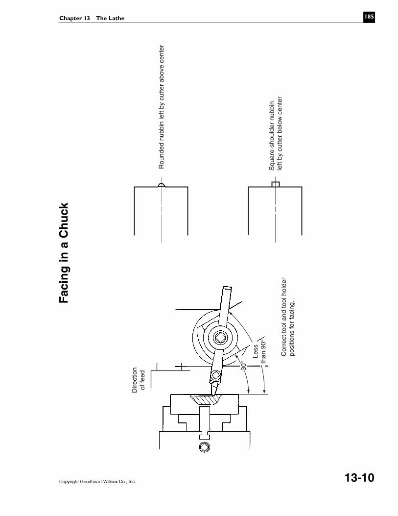
Rou
nded
nub
bin
left
by c
utte
r ab
ove
cent
er
Squ
are-
shou
lder
nub
bin
left
by c
utte
r be
low
cen
ter
Cor
rect
tool
and
tool
hol
der
posi
tions
for
faci
ng.
Less
than
90°
30°
Dire
ctio
nof
feed
Copyright Goodheart-Willcox Co., Inc. 13-10
Faci
ng
in a
Ch
uck
Name: ______________________________________________ Date: _______________ Score: ________
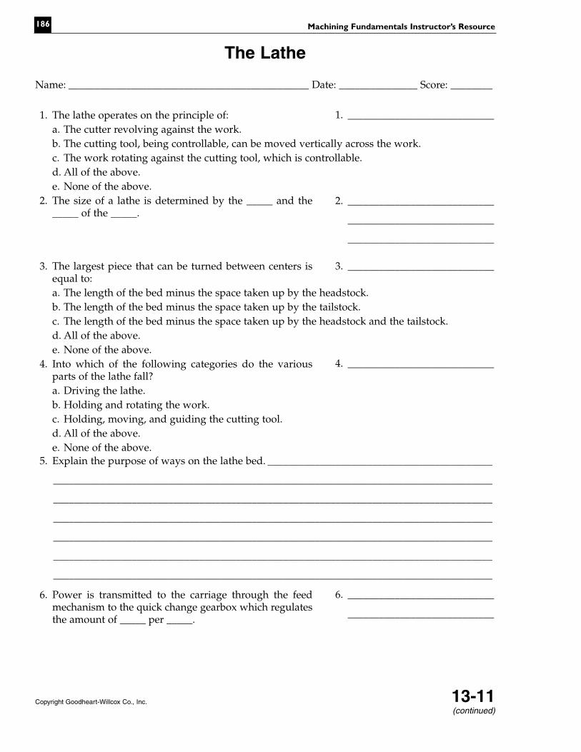
1. The lathe operates on the principle of:a. The cutter revolving against the work.b. The cutting tool, being controllable, can be moved vertically across the work.c. The work rotating against the cutting tool, which is controllable.d. All of the above.e. None of the above.
2. The size of a lathe is determined by the _____ and the_____ of the _____.
3. The largest piece that can be turned between centers isequal to:a. The length of the bed minus the space taken up by the headstock.b. The length of the bed minus the space taken up by the tailstock.c. The length of the bed minus the space taken up by the headstock and the tailstock.d. All of the above.e. None of the above.
4. Into which of the following categories do the variousparts of the lathe fall?a. Driving the lathe.b. Holding and rotating the work.c. Holding, moving, and guiding the cutting tool.d. All of the above.e. None of the above.
5. Explain the purpose of ways on the lathe bed. ___________________________________________
____________________________________________________________________________________
____________________________________________________________________________________
____________________________________________________________________________________
____________________________________________________________________________________
____________________________________________________________________________________
____________________________________________________________________________________
6. Power is transmitted to the carriage through the feedmechanism to the quick change gearbox which regulatesthe amount of _____ per _____.
Machining Fundamentals Instructor’s Resource186
Copyright Goodheart-Willcox Co., Inc. 13-11
The Lathe
1. ____________________________
2. ____________________________
____________________________
____________________________
3. ____________________________
4. ____________________________
6. ____________________________
____________________________
(continued)

7. The carriage supports and controls the cutting tool. Describe each of the following parts:
a. Saddle: ___________________________________________________________________________
____________________________________________________________________________________
____________________________________________________________________________________
b. Cross-slide: _______________________________________________________________________
____________________________________________________________________________________
____________________________________________________________________________________
c. Compound rest: ___________________________________________________________________
____________________________________________________________________________________
____________________________________________________________________________________
d. Tool post: _________________________________________________________________________
____________________________________________________________________________________
____________________________________________________________________________________
8. Accumulated metal chips and dirt are cleaned from thelathe with a _____, never with _____.
9. Which of the following actions are considered dangerouswhen operating a lathe?a. Wearing eye protection.b. Wearing loose clothing and jewelry.c. Measuring with work rotating.d. Operating lathe with most guards in place.e. Using compressed air to clean machine.
10. In most lathe operations, you will be using a single-pointcutting tool made of _____.
11. Cutting speeds can be increased 300% to 400% by using_____ tools.
12. What does cutting speed indicate? _____________________________________________________
____________________________________________________________________________________
____________________________________________________________________________________
____________________________________________________________________________________
____________________________________________________________________________________
____________________________________________________________________________________
13. _____ is used to indicate the distance that the cuttermoves longitudinally in one revolution of the work.
Chapter 13 The Lathe 187
Name: ______________________________________________
8. ____________________________
____________________________
9. ____________________________
10. ____________________________
11. ____________________________
13. ____________________________
Copyright Goodheart-Willcox Co., Inc. 13-11(continued)

14. Calculate the cutting speeds for the following metals.The information furnished is sufficient to do so.
a. Formula: rpm b. CS = Cutting speed recommended for material being machined.c. D = Diameter of work in inches.Problem A: What is the spindle speed (rpm) required to finish-turn 2 1/2″diameter aluminum alloy? A rate of 1000 fpm is the recommended speedfor finish-turning the material.
Problem B: What is the spindle speed (rpm) required to rough-turn 1″diameter tool steel? The recommended rate for rough turning thematerial is 50 fpm.
15. Calculating the cutting speed for metric-size materialrequires a slightly different formula.
a. Formula: rpm = b. CS = Cutting speed recommended for particular material being
machined (steel, aluminum, etc.) in meters per minute (mpm).c. D = Diameter of work in millimeters (mm).
Problem: What spindle speed is required to finish-turn 200 mm diameteraluminum alloy? Recommended cutting speed for the material is 300 mpm.
Machining Fundamentals Instructor’s Resource188
14. ____________________________
15. ____________________________
Name: ______________________________________________
Copyright Goodheart-Willcox Co., Inc. 13-11(continued)
CS × 4D
CS × 1000D × 3

16. Most work is machined while supported by one of four methods. List them.
____________________________________________________________________________________
____________________________________________________________________________________
____________________________________________________________________________________
____________________________________________________________________________________
17. Sketch a correctly drilled center hole.
18. A tapered piece will result, when the work is turned between centers, if the centers are notaligned. Approximate alignment can be determined by two methods. What are they?____________________________________________________________________________________
____________________________________________________________________________________
19. Describe one method for checking center alignment if close tolerance work is to be done betweencenters. _____________________________________________________________________________
____________________________________________________________________________________
____________________________________________________________________________________
____________________________________________________________________________________
____________________________________________________________________________________
20. It is often necessary to turn to a shoulder or to a point where the diameters of the work change.One of four types of shoulders will be specified. Make a sketch of each. Make your sketches on aseparate piece of paper.a. Square shoulder.b. Angular shoulder.c. Filleted shoulder.d. Undercut shoulder.
Chapter 13 The Lathe 189
Name: ______________________________________________
Copyright Goodheart-Willcox Co., Inc. 13-11(continued)

21. What are the four types of lathe chucks most commonly used? Describe the characteristics ofeach. _______________________________________________________________________________
____________________________________________________________________________________
____________________________________________________________________________________
____________________________________________________________________________________
____________________________________________________________________________________
____________________________________________________________________________________
____________________________________________________________________________________
22. When using the parting tool, the spindle speed of themachine is about _____ the speed used for conventionalturning.
23. Why is a concave rake ground on top of the cutter when used for parting operations?____________________________________________________________________________________
____________________________________________________________________________________
____________________________________________________________________________________
24. There are many safety precautions that must be observed when operating a lathe. List what youconsider the five most important. ______________________________________________________
____________________________________________________________________________________
____________________________________________________________________________________
____________________________________________________________________________________
____________________________________________________________________________________
____________________________________________________________________________________
____________________________________________________________________________________
____________________________________________________________________________________
Machining Fundamentals Instructor’s Resource190
Name: ______________________________________________
Copyright Goodheart-Willcox Co., Inc. 13-11
22. ____________________________