learn ssf - cost effective solutions in civil, structural...
TRANSCRIPT

LEARN SSF A Software for Analysis, Design, Estimation & Costing
of Steel Buildings, revised as per IS 800: 2007
By : Y.A. Agboatwala & Fatima.Y. Agboatwala 1802, Jamuna Amrut, 219, Patel Estate, S.V.Road, Jogeshwari(W), Mumbai - 400102 Phone: 09820792254 , (022) 26783525 Url: www.supercivilcd.com, www.agboatwala.com Email : [email protected], [email protected], [email protected]

LEARN SSF
A Software for Analysis, Design, Estimation, Costing and AutoCAD Drawing of Multistory Structural Steel
Buildings As per IS 800 : 2007
Introduction INTRO & LIMITATION
New Project (File) Creation STEP NO. 1
Scan Joint, Beam, Column & Slab Data from AutoCAD Drawing
STEP NO. 2
OR
Automatic Joint Number Creation STEP NO. 2
Delete Un-Wanted Joints STEP NO. 3
Delete and Edit Beams STEP NO. 4
Delete and Edit Columns STEP NO. 5
Delete and Edit Slabs STEP NO. 6
Add & Edit Point Loads to Beam STEP NO. 7
Add & Edit Beam Continuity STEP NO. 8

Data Checking Through Graphics STEP NO. 9
Analysis & Its Results STEP NO. 10
Beam Design, Column Loads & QTY STEP NO. 11
BMD, SFD, Load Display & Files Option STEP NO. 12
Creation of Floor Plan in AutoCAD STEP NO. 13
Design of Multistorey Building Columns STEP NO.14
Column, Project Quantities & Cost STEP NO. 15

LEARN SSF STEP BY STEP
INTRO & LIMITATIONS
Read all Beam to Beam, Beam to Column Connection design with reference to standard details given in the software.
The software performs Analysis, Design, Estimation & Costing of Structural Steel Floors and Columns. Floor Plan shall be at a given Uniform Level (2D). Multiple Level Floors (3D) cannot be analyzed. All Steel Columns shall be Box type i.e. 2MC Toe to Toe OR 2 MB Toe to Toe Welded without any Gap. The Software basically requires a User to enter floor data for Joints, Columns, Beams, Slabs (Grating or Chequered Floor) , Point loads & Continuity. The rest of the things are taken care of by the software. The results are displayed in the form of BM & SF, Beam Design Details, Quantities, Cost & Column Loads. Graphics option are available for display and tabular Format is available for Editing and Deleting Data. A User should Delete / Edit Input-Data through the various Program Options only. If any editing is done outside the design environment than Data files may become corrupted. All Data should be Strictly "Entered" as explained in following steps. Extensive Printing options are available under each display. Printing is straight forward with default set of values ( Arial Font, 8 mm Thick, Bold, Portrait ). The best way to go about the software is to Mark on the Floor Plan, Joint, Beam, Column and Slab Numbers. A Joint represents a Column location or an intersection between 2 Beams. The Beams are represented by its location in the form of Right Hand Side (RHS) & Left Hand Side (LHS) Joint numbers. The Slabs are represented by LEFT BOTTOM & RIGHT TOP joint numbers. All Joints will have X & Y Co-Ordinates, Top Left corner is taken as origin (0, 0). Joint / Beam / Column / Slab numbers should start with " 1 " and should not be repeated. The Program will generate automatic Joint, Beam, Column & Slab Numbers from the information given in Project File. Some of these Numbers / Members may not be required & shall be deleted in a systematic manner as explained in the following chapters. The Final Plan Graphics should look exactly as the Floor Plan.

Cantilever beams cannot be analyzed. Only Vertical Loads & End Moments on Beams are Envisaged. Lateral & Compressive Loads on Beams are not Permitted.
Beams / Columns / Flooring shall be along two mutually perpendicular axis (Z and Y). Polygonal (Multi-sided) Floors cannot be analyzed.
Only three (3) Load Cases can be analyzed per File, viz : ● DL + LL ● { DL + LL + Wind Or Seismic End Moment (WL1). } * 0.8 Wind Or Seismic End Moment shall be entered by the user on individual beams having Columns supports. ● { DL + LL + Wind Or Seismic End Moment (WL2). } * 0.8 Whatever will the value of WL1, the program will reverse its sign (Multiply it by - 1) and use it as the default 3rd Case. ● Multiplication Factor of 0.8 will be applied within the Program by default. End Moments (Wind or Seismic) are obtained by running 2-D or 3-D Portal Frame Analysis programs separately. User may use our 2-D Frame Analysis software for calculation of End Moments. More cases can be obtained by manipulating initial values as given in the project file or individual Beam and Slab files. For example Analysis option can be re-run with LL decreased by 0.8 (0.5* 0.8 = 0.4 T/M2). Similarly masonry thickness can be decreased to get desired loading on the floor. However a designer has to 1st copy the original file in to another file (using Copy Option) & do the above mentioned modifications. MZZ and MYY are Moments due to Wind / Seismic Loads / Eccentricity. If Connection at Joint between Column & Beam is Moment connection than No Moment shall be calculated due to Eccentricity of connection. If Connection at Joint between Column & Beam is Shear connection than Moment shall be calculated due to Eccentricity of connection. Minimum Eccentricity at Shear joints shall be taken as 70 MM + Half of Col. dim. Note that there shall be no Bending Moments due to Wind or Earthquake on Frame (Col or Beam) if Structure is designed as Braced / Non-Sway against lateral loading by Using suitable Shear Wall or Cross Bracing System.

Export to Excel : When the " Analysis Result -> Bending Moment & Reaction " option is Run, a Text file is automatically created. This File will open in Any Text Editor. You can also Open this Text File in EXCEL. Start Excel -> File -> Open -> Delimited ->Next : Delimiters -> Comma ->Next -> Finish. Now you will notice that Complete Data is displayed in Excel Spread Sheet. If more than One File is Created, Corresponding to Each of Load Cases, than Open Excel Sheet for Each File (Load Case). In Excel Sheet Editing, Deleting, Sorting, Printing & Merging of Data/Files/Excel Sheets is Extremely Easy. This way any no. of Load Cases can be Manipulated. Similar Text files are created in " Shear Corrected BM & SF " (Design BM & SF) & " Column Loads " option for Exporting Results to Excel Spread Sheet & its subsequent Manipulation.
Intersecting Joints between two Beams (Main & Secondary) is assumed as Hinged. Hence no Moment transfer is envisaged.
Connection between End Column and Beam is considered as Hinged. Hence no Moment transfer is envisaged between Column and Beam. However End Moments can be applied at joints as mentioned above under Load Case WL1.
After data input, the user has to switch over to graphic option for visual checking of joints / columns / beams / slab nos. When the data is error free the user can run the Analysis, Design and Quantity options. The various results are also available through display or print options.
Analysis, Design and Quantity options should be run in strict order, else program will give unexpected results.
Program creates automatic Joint numbers as per nos. of Horizontal & Vertical Grids. Here Grids means Beams coming along Column center lines as well as all Internal Beams not aligned with columns. A user has to input Information regarding Horizontal & Vertical Grids while creating Project File.
A user can delete the Joints not required by using Joint Option.
Joints will be automatically re-numbered when "UPDATE" button is clicked or at "EXIT".
Remember to Delete / Edit Corresponding Beam / Column / Slab Member, whose Joint has been deleted.
Always delete Beam / Column / Slab member from the "END" to facilitate further Editing. After Deleting press "UPDATE" button for re-numbering of members.
After Deleting corresponding Beam / Column / Slab Member & Updating, edit the required Joint Numbers of affected Beam / Column / Slab Members.
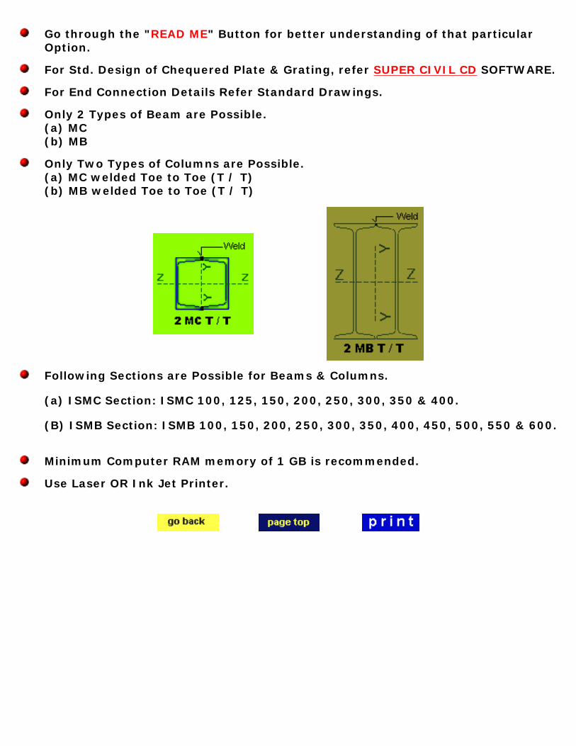
Go through the "READ ME" Button for better understanding of that particular Option.
For Std. Design of Chequered Plate & Grating, refer SUPER CIVIL CD SOFTWARE.
For End Connection Details Refer Standard Drawings.
Only 2 Types of Beam are Possible. (a) MC (b) MB
Only Two Types of Columns are Possible. (a) MC welded Toe to Toe (T / T) (b) MB welded Toe to Toe (T / T)
Following Sections are Possible for Beams & Columns. (a) ISMC Section: ISMC 100, 125, 150, 200, 250, 300, 350 & 400. (B) ISMB Section: ISMB 100, 150, 200, 250, 300, 350, 400, 450, 500, 550 & 600.
Minimum Computer RAM memory of 1 GB is recommended.
Use Laser OR Ink Jet Printer.
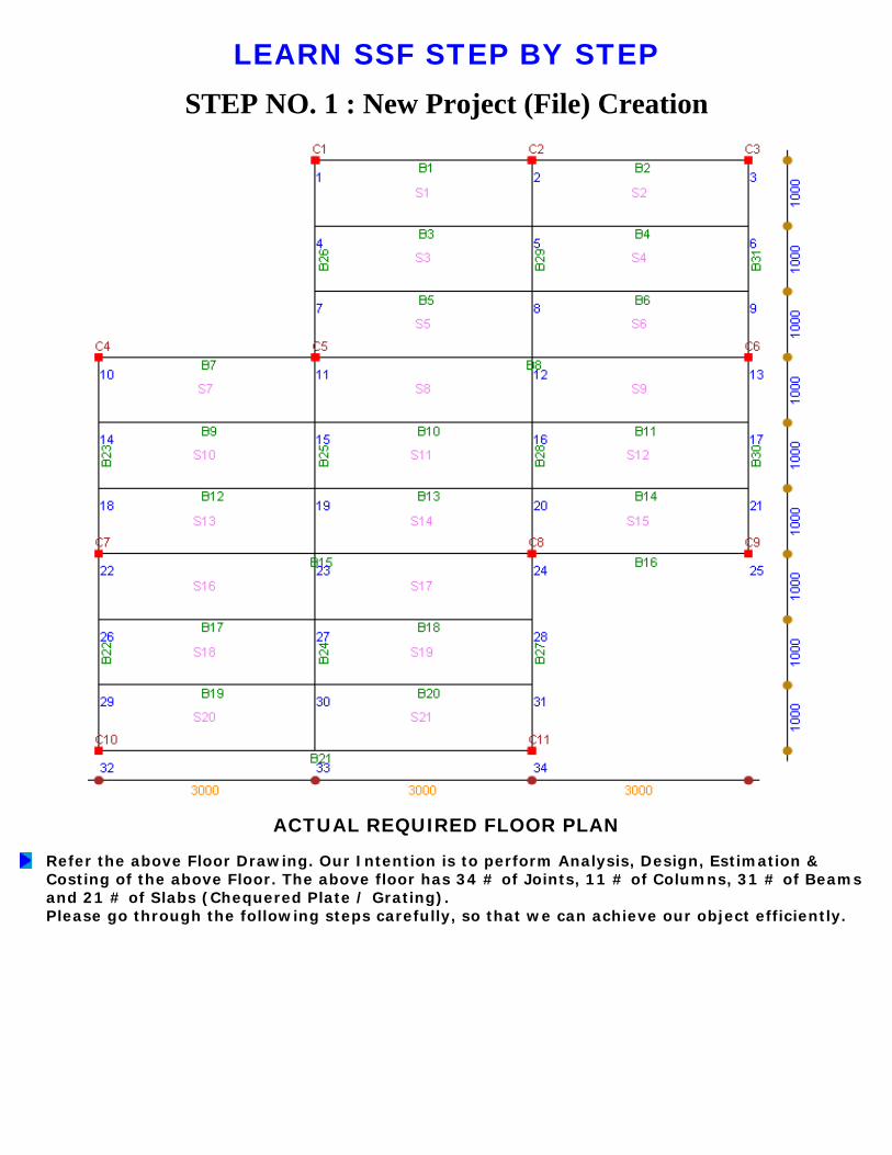
LEARN SSF STEP BY STEPSTEP NO. 1 : New Project (File) Creation
ACTUAL REQUIRED FLOOR PLAN
Refer the above Floor Drawing. Our Intention is to perform Analysis, Design, Estimation & Costing of the above Floor. The above floor has 34 # of Joints, 11 # of Columns, 31 # of Beams and 21 # of Slabs (Chequered Plate / Grating). Please go through the following steps carefully, so that we can achieve our object efficiently.

When Program starts, the graphics above is displayed. Consider the " New Project Option ". Click the " New Project " option in the MENU bar. The following window will open.

You must create a separate Folder / Directory to store your files. I have created a Directory called " 000SSF " in C drive to store my Project files. Now go to this folder & give a file name to your project. I have given " Example_1 " as the name of my new project file. Click the save button. Following project window will open.
The window requires various project details. Whatever values you will fill here will serve as default values for the project. I have filled up the above values as required by my new project " Example_1 ". Please note that you cannot Change / Edit all these values later. Hence be-careful in feeding these initial values. The total floor width & length values will be used to tally the sum of individual Vertical and Horizontal Grids. Here the meaning of Grids means Center Lines Between Column-Beams and also Center Lines of Beams without Columns. Even any isolated Beam is treated as a Grid. The automatic creation of Joint Numbers & Co-Ordinate system depends up on total width, length & No. of vertical & horizontal Grids of floor. Effective length Coefficient is Length of Compression Flange of Beam ÷ Span. If Chequered Plate Or Grating is intermittently welded to Beam Flange than effective length is zero. Generally cross members are connected at 1.0 OR 1.5 M C/C to main Beam, hence Effective length Coefficient can be selected as 0.1 OR 0.2. In case of an isolated Beam it can be taken as 1.0. Hole Diameter is used to arrive at Net Area & Net IXX of Beam. Minimum of 2 Bolt Holes are deducted. Slenderness ratio and Increase in Permissible stress is applicable to both Beams and

Columns. Now click the " Next Page" button, following window will appear.
I have entered the Horizontal Grid distance as 3000 mm for each Bay. The total is 9000 mm, which tally's with the total floor width of 9000 mm which was entered in the earlier page. If there is a mis-match between the two then an error will be displayed. A user can click " Previous Page " button to display the previous page & verify the required total width. Note that distance between vertical Grids means horizontal distance. Start from leftmost grid by referring to the Floor Plan. If all grid distances are same then a user can enter the grid distance once & use " Copy All " button to copy the values to all ROWS. Use Copy & Paste Button to copy & paste values to different rows, in case the grid distances are not same. The " Prev ", " Next ", " Last ", " 1 st ", & " Go to Rec " Buttons are for displaying / Focusing the cursor on Previous, Next, First or required Record Number. The " Clear " Button clears all grid Distance values. The " Print " Button is for printing of values from the Table. Use laser OR Inkjet Printer.
Now click the " Next Page " button, following window will appear.
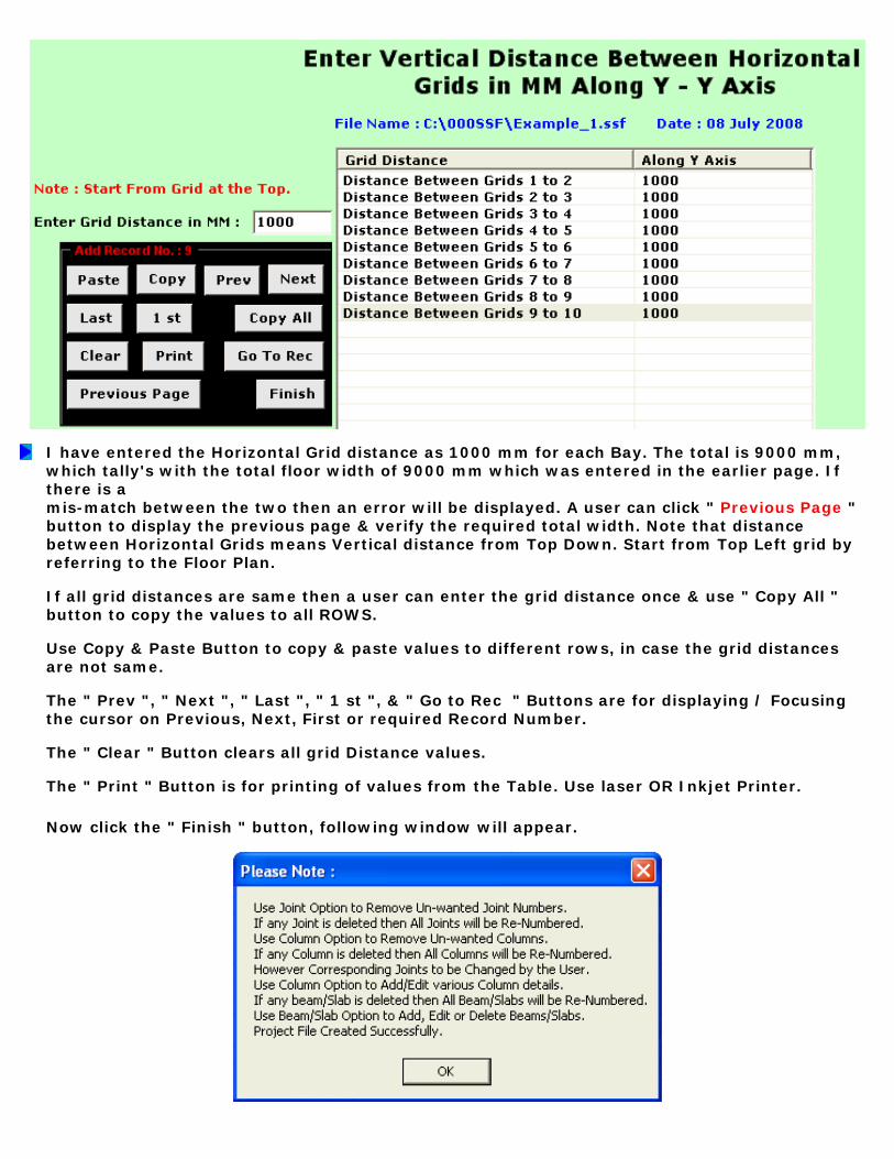
I have entered the Horizontal Grid distance as 1000 mm for each Bay. The total is 9000 mm, which tally's with the total floor width of 9000 mm which was entered in the earlier page. If there is a mis-match between the two then an error will be displayed. A user can click " Previous Page " button to display the previous page & verify the required total width. Note that distance between Horizontal Grids means Vertical distance from Top Down. Start from Top Left grid by referring to the Floor Plan. If all grid distances are same then a user can enter the grid distance once & use " Copy All " button to copy the values to all ROWS. Use Copy & Paste Button to copy & paste values to different rows, in case the grid distances are not same. The " Prev ", " Next ", " Last ", " 1 st ", & " Go to Rec " Buttons are for displaying / Focusing the cursor on Previous, Next, First or required Record Number. The " Clear " Button clears all grid Distance values. The " Print " Button is for printing of values from the Table. Use laser OR Inkjet Printer.
Now click the " Finish " button, following window will appear.

Note the above very important message. If any joint no. is deleted then Joint numbers will be re-numbered. Delete the corresponding Un-Wanted Columns, Beams & Slabs, which belonged to above mentioned deleted Joints. Now the Columns, Beams & Slabs will be automatically re-numbered as Un-wanted members are deleted. Now user should manually change the Joint Numbers of Columns. Similarly RHS & LHS joint numbers of Beams should be changed manually as per the revised (Re-Numbered) joint numbers.
If a User would like to Part Edit / View the Project File, just click " Edit / Display Project File " Option. Following window will display the project file.
Note from above display that AREAS which are Grayed cannot be edited, rest of them can be changed.
STEP NO. 1 IS OVER.

LEARN SSF STEP BY STEPSTEP NO. 2 (Alternate) : Scan Joint, Beam, Column & Slab Data from AutoCAD Drawing
In order to Read the AutoCAD drawing in SSF , the various drawing components should be drawn in their respective layers as shown below. The Drawing Components to be drawn to exact scale and in Millimeter (MM). During the course of a project, a Floor can be extended by adding new Joints, Beams, Columns and Slabs.
Note that the plan should be drawn, such that the coordinate of Top Left corner should be located / shifted (in case of existing drawing) at 0,0 as shown below.
Shown below is a Typical Plan in AutoCAD :
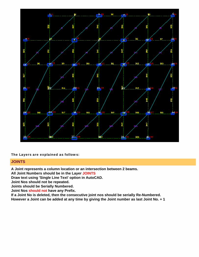
The Layers are explained as follows:
JOINTS
A Joint represents a column location or an intersection between 2 beams. All Joint Numbers should be in the Layer JOINTS Draw text using 'Single Line Text' option in AutoCAD. Joint Nos should not be repeated. Joints should be Serially Numbered. Joint Nos should not have any Prefix. If a Joint No is deleted, then the consecutive joint nos should be serially Re-Numbered. However a Joint can be added at any time by giving the Joint number as last Joint No. + 1

BEAM
All Beam Lines should be drawn under Layer CEN. Only the Beam Centre line is to be drawn. Beams to be drawn at 0 or 90 degrees only. Inclined Beams are not permitted. Keep "ORTHO" Option ON while drafting. Every Beams should be a complete line touching Beam /Column Centre. Every line in layer 'CEN' will be considered as a beam. Beam Width will not be scanned from AutoCAD Drawing. User to indicate Beam Width using Beam Option. If a Beam is deleted, then the consecutive Beam Nos should be serially Re-Numbered. However a Beam can be added at any time by giving the Beam number as last Beam No. + 1
BEAM NUMBERS

All Beam Numbers should be in the Layer BEAMTEXT. Draw text using 'Single Line Text' option in AutoCAD. The angle of Inclination of Beam No's should be the same as the Beam. (ie. If the Beam is inclined at an angle of 90 degrees, the text of the beam should also be inclines at 90 degrees. Beam nos should be as close as possible to the centre of the Beam Line. Beam Nos should not be repeated. Beams should be Serially Numbered. Beam Nos should be prefixed with a "B" (ie. B1, B2)
SLAB
In Order to mark the Extent of Slab, a Diagonal Line should be drawn from left bottom corner to right top corner of Slab as shown below. The Diagonal Lines are to be drawn in the layer SLAB Diagonal Lines should be drawn intersecting Beams or Columns. If a Slab is deleted, then the consecutive Slab Nos should be serially Re-Numbered. However a Slab can be added at any time by giving the Slab number as last Slab No. + 1

SLAB NUMBERS
All Slab Numbers should be in the Layer SLABTEXT. The Slab Text (No.) to be drawn near to the centre of the Slab . Draw text using 'Single Line Text' option in AutoCAD. Slab Nos. should not be repeated. Slabs should be Serially Numbered. Slab Nos should be prefixed with a "S" (ie. S1, S2) Slab Text shall not be inclined. It should be drawn at zero degrees.
COLUMN NUMBERS
All Column Numbers should be in the Layer COLUMNTEXT. Column Nos should be as marked near its Joint. Draw text using 'Single Line Text' option in AutoCAD. Column Nos should not be repeated. Columns should be Serially Numbered. Column Nos should be prefixed with a "C" (ie. C1, C2) Column Size will not be scanned from AutoCAD Drawing. User to indicate Column Size in Column Option. If a Column is deleted, then the consecutive Column Nos should be serially Re-Numbered. However a Column can be added at any time by giving the Column number as last Column No. + 1
CONTINUITY
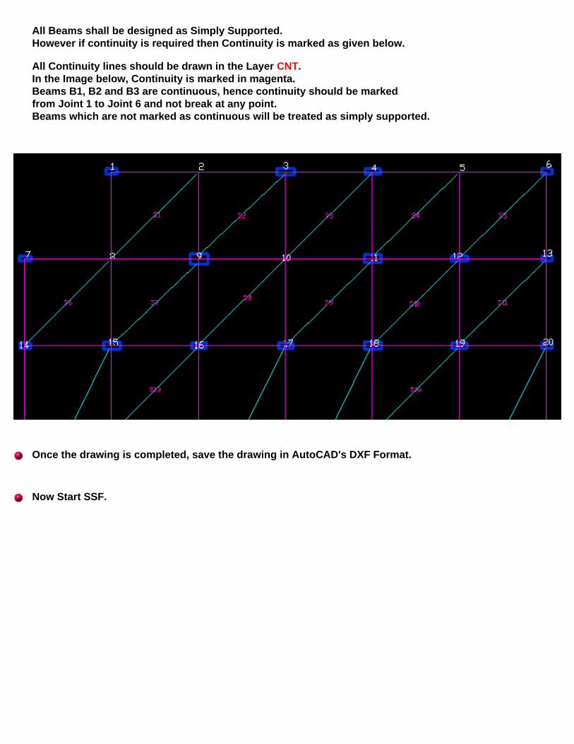
All Beams shall be designed as Simply Supported. However if continuity is required then Continuity is marked as given below. All Continuity lines should be drawn in the Layer CNT. In the Image below, Continuity is marked in magenta. Beams B1, B2 and B3 are continuous, hence continuity should be marked from Joint 1 to Joint 6 and not break at any point. Beams which are not marked as continuous will be treated as simply supported.
Once the drawing is completed, save the drawing in AutoCAD's DXF Format.
Now Start SSF.

When Program starts, the graphics above is displayed. Click the " Scan AutoCAD Plan" option in the MENU bar. The following window will open.

Now select Example _1.ssf File. Following Graphics will be displayed.
Click on browse to select the AutoCAD Drawing. Next click on "Scan/ Read AutoCAD Drawing" button. The Imported data shall be verified using Edit/ Delete/ Add/ Display Joint, Beam, Column and Slab as well as Graphics Option of Joint, Beam, Column and Slab. The Graphic Display and AutoCAD Drawing should appear same. Do not perform analysis, if there is any discrepancy in drawings shown in various Graphic Options and AutoCAD.
STEP NO. 2 IS OVER.
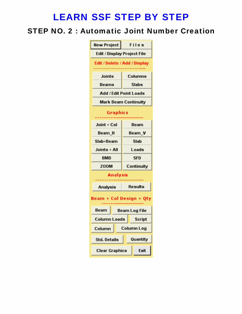
LEARN SSF STEP BY STEPSTEP NO. 2 : Automatic Joint Number Creation
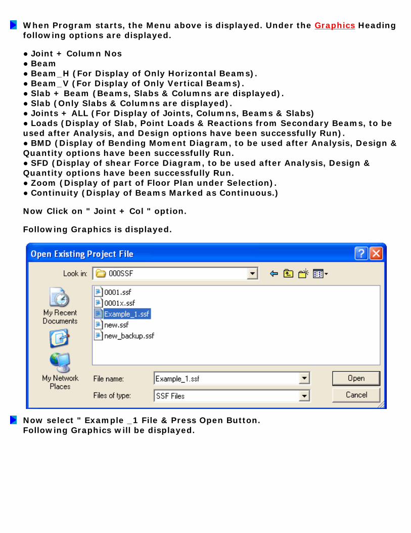
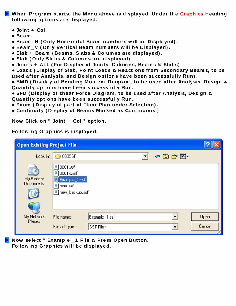
When Program starts, the Menu above is displayed. Under the Graphics Heading following options are displayed. ● Joint + Column Nos ● Beam ● Beam_H (For Display of Only Horizontal Beams). ● Beam_V (For Display of Only Vertical Beams). ● Slab + Beam (Beams, Slabs & Columns are displayed). ● Slab (Only Slabs & Columns are displayed). ● Joints + ALL (For Display of Joints, Columns, Beams & Slabs) ● Loads (Display of Slab, Point Loads & Reactions from Secondary Beams, to be used after Analysis, and Design options have been successfully Run). ● BMD (Display of Bending Moment Diagram, to be used after Analysis, Design & Quantity options have been successfully Run. ● SFD (Display of shear Force Diagram, to be used after Analysis, Design & Quantity options have been successfully Run. ● Zoom (Display of part of Floor Plan under Selection). ● Continuity (Display of Beams Marked as Continuous.) Now Click on " Joint + Col " option. Following Graphics is displayed.
Now select " Example _1 File & Press Open Button. Following Graphics will be displayed.

Note that Joints Numbers (Including X & Y Co-Ordinates) and Columns are created and displayed automatically at all the intersections of vertical & horizontal grids. Some of the Joint numbers may not be required. A Joint represents a column location or an intersection between 2 beams. The beams are represented by its location in the form of Right Hand Side (RHS) & Left Hand Side (LHS) Joint numbers. The slabs are represented by TOP LEFT & RIGHT BOTTOM joint numbers. Additionally we have displayed above RHS and LHS conventions for Horizontal & Vertical Orientations in the form of Arrows. Now click the " Joints + ALL " button, following Graphics will be displayed.

AUTOMATICALLY GENERATED FLOOR PLANNote that Columns are shown at all the Joints, and Beams are spanning between these columns. This is different than what is the actually required Floor Plan. The intended actual floor plan is reproduced below.

ACTUAL REQUIRED FLOOR PLANOur Actual RCC Floor Plan has only 21 numbers of Slabs, 11 numbers of Columns and 31 numbers of Beams. The automatic generated plan has 27 numbers of Slabs, 40 numbers of Columns and 66 numbers of Beams. Hence we have to delete these extra Slabs, Columns and Beams along with their appropriate Joint numbers. Let us delete these parameters in next step.
STEP NO. 2 IS OVER.


LEARN SSF STEP BY STEPSTEP NO. 3 : Delete Un-Wanted Joints
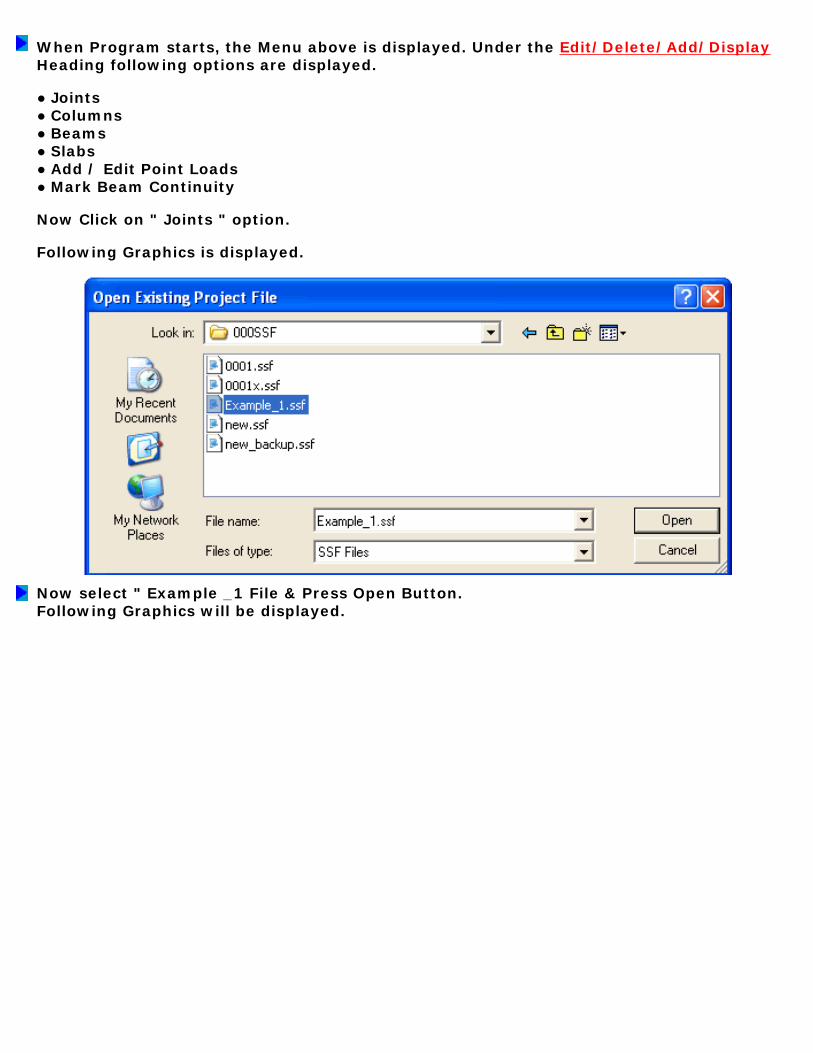
When Program starts, the Menu above is displayed. Under the Edit/Delete/Add/Display Heading following options are displayed. ● Joints ● Columns ● Beams ● Slabs ● Add / Edit Point Loads ● Mark Beam Continuity Now Click on " Joints " option. Following Graphics is displayed.
Now select " Example _1 File & Press Open Button. Following Graphics will be displayed.

Here we have 40 Joint numbers. The Actual required are only 34. Hence we have to delete the extra joint numbers (40-34 = 6). Select Joint number 1 & press " Remove " button. Joint Number " 1 " is deleted. Now Click " UPDATE ", joints will be re-numbered. Now Select Joint number " 3 " & press " Remove " button. Joint Number " 3 " is deleted. Now Click " UPDATE ", joints will be re-numbered. Similarly select other Joints & press remove & update button till Joint number 34 is reached. You should keep a copy of Required Floor Plan & Automatically generated Floor Plan in front of you. Always update after each remove. In this way complete joint numbers can be updated. Now Click on " Joint Nos " option under the Graphics Caption. You will see the revised Joint number Layout as displayed below.

Note the Critical Data Error " Check Joint / Beam / Slab / Column data ". What it means is that you have not deleted corresponding Beam (s) / Slab (s) / Column (s) which refers to deleted Joints. The " Copy All " button copies data from the selected ROW to all the ROWS. Later on a user can change the values selectively. Use Copy & Paste Button to copy & paste values to different rows, in case the values are not same. The " Prev ", " Next ", " Last ", " 1 st ", & " Go to Rec " Buttons are for displaying / Focusing the cursor on Previous, Next, First or required Record Number. The " Clear " Button clears all values. The " Print " Button is for printing of values from the Table. Use laser OR Inkjet Printer. The " Add Record " button is very important one. If a user has deleted any joint by mistake, than he can easily add the record back by pressing this button. However the Joint number added will be the last + one number. Suppose after deleting a joint, total joints left are 99, then if "Add Record" button is pressed, the next record displayed will be

joint number 100. Remember that a user cannot give joints " X " and " Y " Co-Ordinates outside the boundary limit as set out in the project file (Refer Step No. 1). In our " Example_1 " Project the maximum width is 9000 and maximum length is 9000. If a user is not comfortable with automatic generation of joint numbers (Co-Ordinates) , then he can use Add Record option to enter complete joint data & corresponding Co-Ordinates manually by first clearing the old data by pressing " Clear " button. Similarly Add Record button can be used for effectively where a floor plan is rather complex, having lots of internal secondary beams in either direction.
Now click the " Read Me " button, the following important messages are displayed. 1. Origin (0,0) is at Top Left Hand Corner. Co-Ordinates Cannot be Negative. 2. There shall not be any difference in Maximum Horizontal & Vertical Distance between Project File & Joint File. 3. Joint Number should start with 1 & not 0. 4. Joints Numbers cannot be repeated. 5. Co-ordinates cannot be repeated. 6. Max. Joints Number = Max. Record Number. 7. Joints should be Serially Numbered. 8. Use Add Button to Append Record. 9. Use Update Button to Re-Number & Save Your Work. 10. In case any Joint # is Deleted or Edited then, Do not Forget to Edit Corresponding Column, Beam & Slab to reflect above change.
Now we have come to the end of Step # 3. In the next step we will delete the un-wanted Beams.
STEP NO. 3 IS OVER.

LEARN SSF STEP BY STEPSTEP NO. 4 : Delete & Edit Beams
When Program starts, the Menu above is displayed. Under the Edit/Delete/Add/Display Heading following options are displayed. ● Joints ● Columns ● Beams ● Slabs ● Add / Edit Point Loads ● Mark Beam Continuity Now Click on " Beams " option. Following Graphics is displayed.

Now select " Example _1 File & Press Open Button. Following Graphics will be displayed.

Here we have 66 numbers of Beams. Actual required are only 31 numbers of Beams (Refer Step No. 1 - Actual Required Floor Plan). Go down to the last beam number B66 and press " Remove " button. You will notice that Beam B66 is deleted. Similarly delete the next beam, till you reach Beam number B31. I am deleting from the end (Last Beam) for ease of editing, you can even start from the beginning or from any other beam number. Click " Update " button. This will re-number all the beams if required. Now let us start editing the RHS & LHS Joint numbers of Beams. Go to first Beam B3 & Select it (Click with Cursor). Now concentrate on the Text Boxes below. Beam # will be shown as B3. LHS Joint # is shown as 3 and RHS joint # is shown as 4. Change LHS Joint # to 4 & RHS Joint # to 5 by editing the text box. Again select Beam # B5 or Click " Next " button. RHS Joint # is shown as 6, change it to 7. LHS Joint # is shown as 7, change to 8. Similarly edit the rest of Beam's RHS & LHS Joint numbers as required by our Actual Floor Plan. In case you would like to EXIT program after partial editing, first use " Update " button to save your work & then click " OK " button. The program will ask you about exiting, click Yes & quit.
All other Beam Parameters Viz; Beam Type, Beam Section, Masonry Height, Masonry Thickness, RHS BM, LHS BM and Any Extra UDL can be Added / Edited for individual Beams by clicking at respective Text Boxes. Beam Span is displayed in Yellow Text Box.
Now click the " Read Me " button, the following important messages are displayed for guidance. 1. Add Joint Details before Beams. 2. Beam Number should start with 1 & not 0. 3. Beam Numbers cannot be repeated. 4. Beam LHS & RHS Joint #s cannot be repeated. 5. Beam Width / Depth < 150 mm not allowed. 6. Beam Width / Depth > 3500 mm not allowed. 7. Max. (LHS or RHS) Beam Joint # cannot > Max. Joint File #. 8. Use Add Button to Append Record. 9. Use Update Button to Re-Number & Save Your Work. 10. Max. Beam Number = Max. Record Number. 11. Beam Nos. Shall be Numbered Serially. 12. Beam LHS OR RHS Joint Number Cannot < = 0.0 13. LHS : Left Hand Side, RHS : Right Hand Side. 14. If Beam is Vertical then, LHS Y-Co Ordinate > RHS Y-Co Ordinate. 15. If Beam is Horizontal then, LHS X-Co Ordinate < RHS X-Co Ordinate.
Now we have come to the end of Step # 4. In the next step we will Delete and Edit un-wanted Columns.
STEP NO. 4 IS OVER.

LEARN SSF STEP BY STEPSTEP NO. 5 : Delete & Edit Columns

When Program starts, the Menu above is displayed. Under the Edit/Delete/Add/Display Heading following options are displayed. ● Joints ● Columns ● Beams ● Slabs ● Add / Edit Point Loads ● Mark Beam Continuity Now Click on " Columns " option. Following Graphics is displayed.
Now select " Example _1 File & Press Open Button.
DISPLAY / EDIT / BOX COLUMN DETAILS

You will notice that here we have 40 numbers of Columns. Actual required are only 11 numbers of Columns. (Refer Step No. 1 - Actual Required Floor Plan). Go down to the last Column number C40 and press " Remove " button. You will notice that Column C40 is deleted. Similarly delete the next Column, till you reach Column number C11. I am deleting from the end (Last Column) for ease of editing, you can even start from the beginning or from any other Column number. Click " Update " button. This will re-number all the Columns if required. Now let us start editing the Joint numbers of Columns. Go to first Column & Select it (Click with Cursor), or click the " 1 st " button. Now concentrate on the Text Boxes below. Column # will be shown as C1. Joint # is shown as 1, which is ok. Again select Column # C4 . Joint # is shown as 4, change it to 10. Similarly edit the rest of Column's Joint numbers as required by our Actual Floor Plan (Refer Step 2). Now your Display will look like the Graphics shown above. In case you would like to EXIT program after partial editing, first use " Update " button to save your work & then click " OK " button. The program will ask you about exiting, click Yes & quit.
All other Box Column Parameters Viz; Column Type, Column Section, Lxx, Lyy, BM_XX & BM_YY can be Added / Edited for individual Columns by clicking at respective Text Boxes. Note that Box Column Type is either 2 MC Toe to Toe OR 2 MB welded Toe to Toe without any Gap. Column Section is either MC or MB. External Load is the additional Vertical Load (+ / -) which can be applied to Column. Click Display Column Orientation button, following window will open.

Now click the " Read Me " button, the following important messages are displayed for guidance. 1. Column Number should start with 1 & not 0. 2. Column Numbers cannot be repeated. 3. Column Joint #s cannot be repeated. 4. All Columns are Deemed Box Columns. 5. Max. Column Joint # cannot > Max. Joint File #. 6. All Columns are assumed as Positioned Centered with respect to Beam / Wall from either Sides. 7. Use Add Button to Append Record. 8. Max. Column Number = Max. Record Number. 9. Columns Shall be Numbered Serially. 10. Use Update Button to Re-Number & Save Your Work. 11. Column Joint Number cannot be < = 0.0 12. BM Z-Z, BM Y-Y, Leff Z-Z, Leff Y-Y are Bending Moments and Column Effective Lengths about Z-Z / Y-Y axis. 13. Externally Applied Load (+/-) on Column Could be due to Wind/Seismic/Truss/Gantry etc. 14. All Loads Shall be Un-Factored. 15. Under normal orientation Z-Z is Horizontal and Y-Y is Vertical Axis. If section is rotated, Z-Z Axis will become Vertical & Y-Y will become Horizontal. 16. Hence user to give MZZ & MYY, LZZ & LYY Parameters accordingly. 17. Enter Maximum of SF from either direction. 18. All Loads Shall be Un-Factored. 19. MZZ & MYY are Moments due to Wind / Seismic Loads / Eccentricity. Wind / Seismic MZZ or MYY are to be given one at a time & not together, unless both of them are acting together at the same time. MZZ & MYY Moments due to Eccentricity shall be given together for shear connection. 21. If Connection at Joint between Column & Beam is Moment connection than No Moment shall be calculated due to Eccentricity of connection. 22. If Connection at Joint between Column & Beam is Shear connection than Moment

shall be calculated due to Eccentricity of connection. 23. Minimum Eccentricity at Shear joints shall be taken as 70 MM + Half of Col. dimension. 24. Note that there shall be no Bending Moments due to Wind or Earthquake on Frame (Col or Beam) if Structure is designed as Braced / Non-Sway against lateral loading by Using suitable Shear Wall or Cross Bracing System.
Now we have come to the end of Step # 5. In the next step we will Delete and Edit un-wanted Slabs.
STEP NO. 5 IS OVER.
LEARN SSF STEP BY STEPSTEP NO. 6 : Delete & Edit Slabs
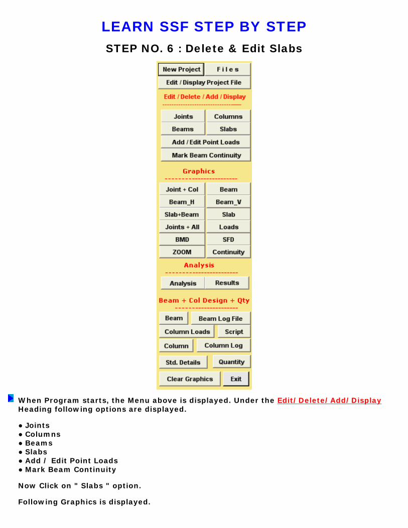
When Program starts, the Menu above is displayed. Under the Edit/Delete/Add/Display Heading following options are displayed. ● Joints ● Columns ● Beams ● Slabs ● Add / Edit Point Loads ● Mark Beam Continuity Now Click on " Slabs " option. Following Graphics is displayed.

Now select " Example _1 File & Press Open Button. Following Graphics will be displayed.
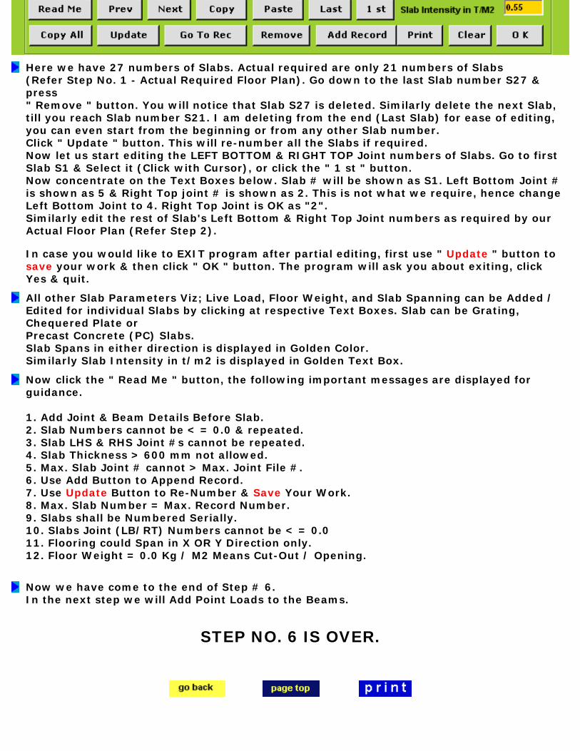
Here we have 27 numbers of Slabs. Actual required are only 21 numbers of Slabs (Refer Step No. 1 - Actual Required Floor Plan). Go down to the last Slab number S27 & press " Remove " button. You will notice that Slab S27 is deleted. Similarly delete the next Slab, till you reach Slab number S21. I am deleting from the end (Last Slab) for ease of editing, you can even start from the beginning or from any other Slab number. Click " Update " button. This will re-number all the Slabs if required. Now let us start editing the LEFT BOTTOM & RIGHT TOP Joint numbers of Slabs. Go to first Slab S1 & Select it (Click with Cursor), or click the " 1 st " button. Now concentrate on the Text Boxes below. Slab # will be shown as S1. Left Bottom Joint # is shown as 5 & Right Top joint # is shown as 2. This is not what we require, hence change Left Bottom Joint to 4. Right Top Joint is OK as "2". Similarly edit the rest of Slab's Left Bottom & Right Top Joint numbers as required by our Actual Floor Plan (Refer Step 2). In case you would like to EXIT program after partial editing, first use " Update " button to save your work & then click " OK " button. The program will ask you about exiting, click Yes & quit.
All other Slab Parameters Viz; Live Load, Floor Weight, and Slab Spanning can be Added / Edited for individual Slabs by clicking at respective Text Boxes. Slab can be Grating, Chequered Plate or Precast Concrete (PC) Slabs. Slab Spans in either direction is displayed in Golden Color. Similarly Slab Intensity in t/m2 is displayed in Golden Text Box.
Now click the " Read Me " button, the following important messages are displayed for guidance. 1. Add Joint & Beam Details Before Slab. 2. Slab Numbers cannot be < = 0.0 & repeated. 3. Slab LHS & RHS Joint #s cannot be repeated. 4. Slab Thickness > 600 mm not allowed. 5. Max. Slab Joint # cannot > Max. Joint File #. 6. Use Add Button to Append Record. 7. Use Update Button to Re-Number & Save Your Work. 8. Max. Slab Number = Max. Record Number. 9. Slabs shall be Numbered Serially. 10. Slabs Joint (LB/RT) Numbers cannot be < = 0.0 11. Flooring could Span in X OR Y Direction only. 12. Floor Weight = 0.0 Kg / M2 Means Cut-Out / Opening.
Now we have come to the end of Step # 6. In the next step we will Add Point Loads to the Beams.
STEP NO. 6 IS OVER.

LEARN SSF STEP BY STEPSTEP NO. 7 : Add & Edit Point Loads to Beam
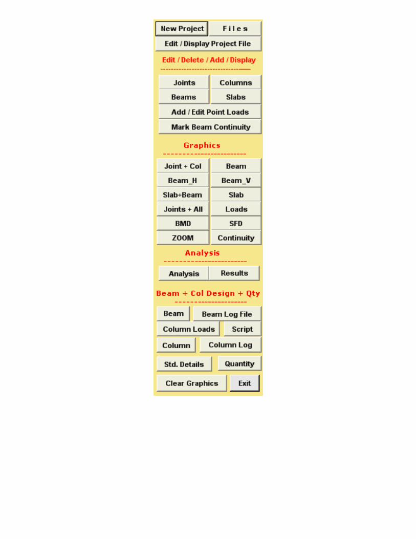
When Program starts, the Menu above is displayed. Under the Edit/Delete/Add/Display Heading following options are displayed. ● Joints ● Columns ● Beams ● Slabs ● Add / Edit Point Loads ● Mark Beam Continuity Now Click on " Add / Edit Point Loads " option. Following Graphics is displayed.
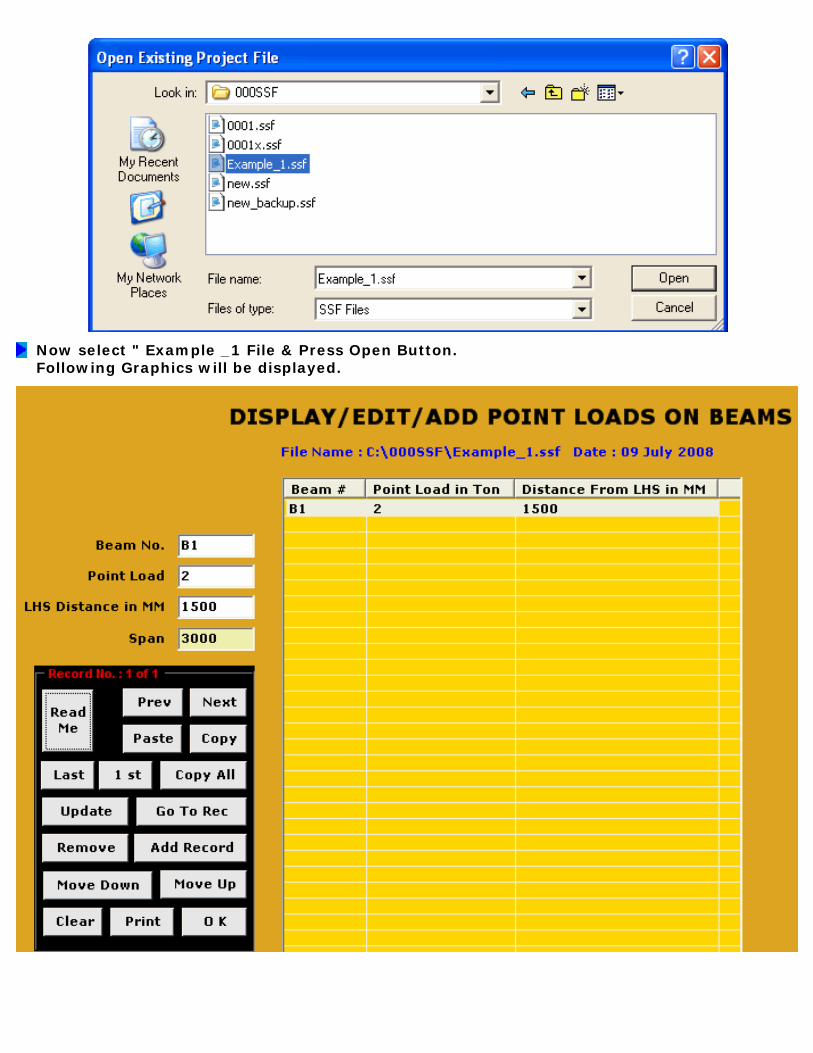
Now select " Example _1 File & Press Open Button. Following Graphics will be displayed.

Click " Add Record " button to Add Point Load to a Beam. When Add Record button is clicked, Beam No. Text Box will show B1. You can edit Text Box to change this beam no. Enter required Externally Applied Point Load & its distance from Left. The distance should not exceed the Span as displayed just below. Just like any other option, here also a user can Display, Add, Edit & delete the Point Load records at the same time. The " Move Up " and " Move Down " buttons will move the record Up or Down the Table respectively. This is useful if you would like to keep the point loads on the same beam serially. You can add any number of point Loads. Do not repeat the same load & location. In case you would like to EXIT program after partial Adding / Editing, first use " Update " button to save your work & then click " OK " button. The program will ask you about exiting, click Yes & quit.
Now click the " Read Me " button, the following important messages are displayed for guidance. 1. LHS & RHS Joint #s cannot be repeated. 2. Enter Point Loads due to Externally Applied Loads Only. 3. Reactions due to Secondary Beams are Calculated Automatically. 4. Use Add Button to Append Record. 5. Use Update Button to Save Your Work.
Now we have come to the end of Step # 7. In the next step we will Mark Beam Continuity.
STEP NO. 7 IS OVER.

LEARN SSF STEP BY STEPSTEP NO. 8 : Add & Edit Beam Continuity

When Program starts, the Menu above is displayed. Under the Edit/Delete/Add/Display Heading following options are displayed. ● Joints ● Columns ● Beams ● Slabs ● Add / Edit Point Loads ● Mark Beam Continuity Now Click on " Mark Beam Continuity " option. Following Graphics is displayed.
Now select " Example _1 File & Press Open Button. Following Graphics will be displayed.
From the above note, it is prudent to design all Beams as Simply Supported. Click "OK" button, a new message is displayed.

If you want to keep all Beams as Simply Supported than Click Yes, Else Click No. We will click "No" to show you next screen.
Click " Add Record " button to Add a Continuous Beam. Record # " 1 " will be displayed in the Text Box, When Add Record button is clicked. Refer our Actual Floor Plan (Step No. 2). Enter " 1 " & " 3 " in the corresponding Text Boxes of LHS Joint & RHS Joint. This means that Beams are continuous from Joint numbers 1 to 3 (B1 & B2). Similarly Add all other continuous beams can be Marked. If any Beam(s) are not marked as continuous than it will be treated as Simply Supported in Analysis. Just like any other option, here also a user can Display, Add, Edit & delete the records at the same time. The " Move Up " and " Move Down " buttons will move the record Up or Down the Table respectively. This is useful if you would like to keep the Records serially. In case you would like to EXIT program after partial Adding / Editing, first use " Update " button to save your work & then click " OK " button. The program will ask you about exiting, click Yes & quit.

Remove the continuity record by clicking on "Remove" button, we do not want any continuous Beams.
Now click the " Read Me " button, the following important messages are displayed for guidance. 1. LHS & RHS Joint #s cannot be repeated. 2. Use Add Button to Append Record. 3. Use Update Button to Save Your Work. 4. LHS / RHS Joint Numbers cannot be zero.
Now we have come to the end of Step # 8. In the next step we will Check our Data Input Graphically.
STEP NO. 8 IS OVER.

LEARN SSF STEP BY STEPSTEP NO. 9 : Data Checking Through Graphics
A User should thoroughly check Data Input at all stages. During Adding / Editing Data through tables, Beam " SPAN " and Slab Dimensions (Shorter & Longer) should be constantly monitored for any error. After DATA Input is over, it should be checked visually & by taking printouts of various Graphics Options. Analysis, Design, Column Loads and Quantities options shall be run (in strict order) after Data Checking is over. If there is any error in DATA, un-expected results will be obtained after running Analysis, Design, Column Loads and Quantities options. Sometimes results obtained are such that it will be difficult to even find out that actually they are wrong due to erroneous data. Any Analysis & Design is as good as its data input. Hence the importance of Data Input cannot be over emphasized. Note that BMD is drawn on Tension Side which reflects Deflected shape of Beam. BMD, SFD and Load Diagrams are Important from the point of Checking Un-expected Analysis Results & Data Input. Any un-expected Diagram will reflect Data Error in the form of : ● Incorrect Geometry (Span, Grid Dimension). ● Incorrect Loads (Point Load, End Moments). ● Floor Analysis & Beam Design not performed after Editing / Adding Geometry or Loads. Under " Column Load " Option Statistical Check is displayed. Note that the Difference in Loads is due to Maximum Loading On Column, due to External Loads / Beam Continuity / End Moments, i.e. Maximum of Simple Reaction & Continuous Reaction is taken for Column Design. If the difference is High, a user should look closer at the Data-Input for any Error. The Most effective check will be when AutoCAD drawing of floor plan is created using Script option. The script command will be used after Successful Completion of Analysis, Design & Quantity options. In AutoCAD drawing, even the minor error in layout could be identified. We will discuss this in Step no. 13.
When Program starts, the Menu above is displayed. Under the Graphics Heading following options are displayed. ● Joint + Col ● Beam ● Beam_H (Only Horizontal Beam numbers will be Displayed). ● Beam_V (Only Vertical Beam numbers will be Displayed). ● Slab + Beam (Beams, Slabs & Columns are displayed). ● Slab (Only Slabs & Columns are displayed). ● Joints + ALL (For Display of Joints, Columns, Beams & Slabs) ● Loads (Display of Slab, Point Loads & Reactions from Secondary Beams, to be used after Analysis, and Design options have been successfully Run). ● BMD (Display of Bending Moment Diagram, to be used after Analysis, Design & Quantity options have been successfully Run. ● SFD (Display of shear Force Diagram, to be used after Analysis, Design & Quantity options have been successfully Run. ● Zoom (Display of part of Floor Plan under Selection). ● Continuity (Display of Beams Marked as Continuous.) Now Click on " Joint + Col " option. Following Graphics is displayed.
Now select " Example _1 File & Press Open Button. Following Graphics will be displayed.
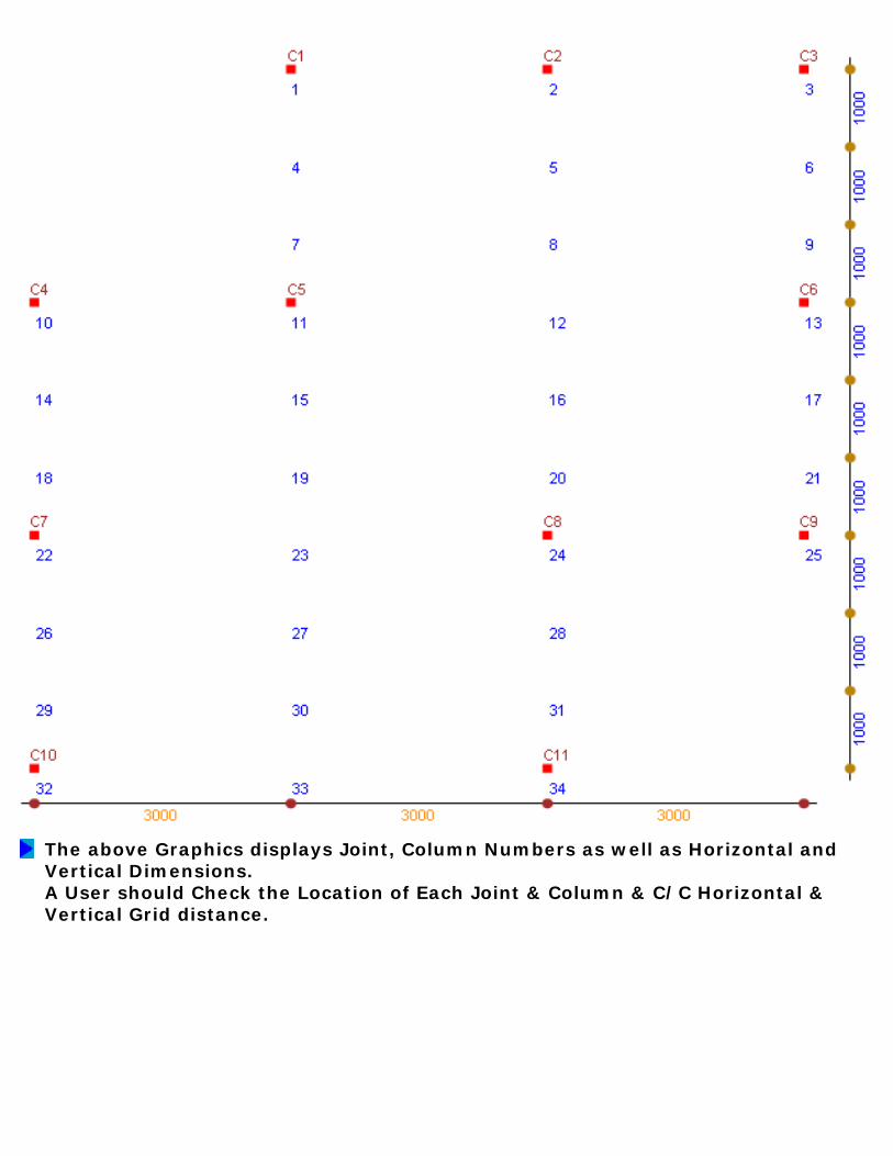
The above Graphics displays Joint, Column Numbers as well as Horizontal and Vertical Dimensions. A User should Check the Location of Each Joint & Column & C/C Horizontal & Vertical Grid distance.

Now click the " Joints + ALL " button. This is the all important Graphics Display, showing Joints numbers, Columns, Beam numbers and Slab numbers. If this display is not very Clear or Congested than use other options such as Beam, Beam_H (Only Horizontal Beam # will be Displayed), Beam_V (Only Vertical Beam # will be Displayed), Slab + Beam (Beams, Slabs & Columns are displayed), Slab (Only Slabs & Columns are displayed) and Zoom Option. Following Graphics is displayed when " Joints + ALL " button is clicked.

Now Click " Beam " button & after display of Graphics click " ZOOM " button. Now Left Click with mouse near the Column C11 & Drag it near the Column C25. You will see change in color in window as mouse is dragged. Now Lift your finger. Following ZOOM Window is displayed. Use Zoom option for more clarity on Floor plan display.

Note that Graphics Display of : ● Loads (Display of Slab, Point Loads & Reactions from Secondary Beams, to be used after Analysis, and Design options have been successfully Run). ● BMD (Display of Bending Moment Diagram, to be used after Analysis, Design & Quantity options have been successfully Run. ● SFD (Display of shear Force Diagram, to be used after Analysis, Design & Quantity options have been successfully Run. Now we have come to the end of Step # 9. In the next step we will Run " Analysis " option.
STEP NO. 9 IS OVER.

LEARN SSF STEP BY STEPSTEP NO. 10 : Analysis & Its Results
After entering Data & Checking it thoroughly, Relax, let the software do its Job. The 1st milestone is Analysis. When Program starts, the Menu above is displayed. Under the Analysis Heading following options are displayed. ● Analysis ● Results Now Click on " Analysis " option. Following Graphics is displayed.
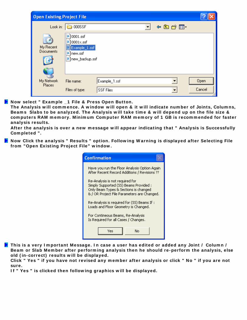
Now select " Example _1 File & Press Open Button. The Analysis will commence. A window will open & it will indicate number of Joints, Columns, Beams Slabs to be analyzed. The Analysis will take time & will depend up on the file size & computers RAM memory. Minimum Computer RAM memory of 1 GB is recommended for faster analysis results. After the analysis is over a new message will appear indicating that " Analysis is Successfully Completed ".
Now Click the analysis " Results " option. Following Warning is displayed after Selecting File from "Open Existing Project File" window.
This is a very Important Message. In case a user has edited or added any Joint / Column / Beam or Slab Member after performing analysis then he should re-perform the analysis, else old (in-correct) results will be displayed. Click " Yes " if you have not revised any member after analysis or click " No " if you are not sure. If " Yes " is clicked then following graphics will be displayed.

Now Double Click on " Loads on Beam " Option. A new window will open displaying various Loads on Beams. Click on " Read Me " button, following important messages are displayed. 1. UDL is in T / M." 2. RHS_MOM : Right Hand Side Moment is in T-M. 3. LHS_MOM : Left Hand Side Moment is in T-M. 4. Point Load is in Ton." 5. Point Load Could be Externally Applied OR 6. From Reaction of Secondary beam. 7. Dist : is distance of Point Load from Left. 8. NEAR_INT : is Slab Load in T/M Near to LHS of Beam. 9. NEAR_DIST : is Slab Load Distance in M Near to LHS. 10. FAR_INT : is Slab Load in T/M Far from LHS. 11. FAR_DIST : is Slab Load Distance in M Far from LHS. 12. Note that NEAR_INT = FAR_INT, as Slabs are Spanning One Way.
Now Double Click on " FEM & SS Reactions " Option. A new window will open displaying Fixed End Moments and Simply Supported Reaction on each Beam. Click on " Read Me " button, following important messages are displayed. 1. Beam Span in M. 2. LHS SS Reaction : LHS Simply Supported Reaction in Ton. 3. RHS SS Reaction : RHS Simply Supported Reaction in Ton. 4. LFEM : Fixed End Moment at LHS Support in T-M. 5. RFEM : Fixed End Moment at RHS Support in T-M. 6. In order to Sort the Values in Ascending OR 7. Descending Order, Just Click Column Header at Top.
Now Double Click on " Bending Moments and Reactions " Option. This is the most Important Option. A new window will open displaying End Moments and Reactions on each Beam. Click on " Read Me " button, following important messages are displayed. 1. -Ve BM at LHS Support in T-M. 2. -VE BM at RHS Support in T-M. 3. LHS Reaction in Tons. 4. RHS Reaction in Ton. 5. + VE Bending Moment in T-M. 6. Distance of + VE BM from LHS Support in M. 7. Load Cases are (a) DL + LL (b) DL + LL + WL1 & 8. (c) DL + LL + WL2. The Case (c) is automatically 9. Calculated as -1 x Case (b).

10. WL1 is due to Externally applied Wind/EQ Moment. 11. In order to Sort the Values in Ascending OR 12. Descending Order, Just Click Column Header at Top. Shown below is a part Display of Support BM, SF, + Ve BM & Its Distance from Left.
DISPLAYING BENDING MOMENTS AND REACTIONS
Note that Column Headers are all the Titles at Top. Just Click them to Sort. The " Remove " Button is placed here for ease of Printing. In case a User wants to Print only DL + LL case, then he can simply delete other cases (DL + LL + WL1 WL2). For Printing Just Click " Print " Button. When " OK " button is clicked, following Important Message is displayed.

The above message describes how any number of Load Cases can be Run & Manipulated once File is Exported to Excel Spread Sheet. Note the File Name Carefully. Similar File is created for " Shear Corrected BM & SF " option. Now Double Click on " Shear Corrected BM & SF " Option. These values are used for Beam Design. A new window will open displaying Shear Corrected Moments and Shear Forces on each Beam for all the three (3) cases. Click on " Read Me " button, following important messages are displayed. 1. Beam Width, Depth in MM. 2. Shear Corrected BM & SF are calculated at Support Face 3. and At Effective Depth from Support Face Respectively. 4. LHS / RHS Shear Corrected BM in T-M. 5. LHS Shear Corrected Shear in Tons. 6. RHS Shear Corrected Shear in Tons. 7. Load Cases are (a) DL + LL (b) DL + LL + WL1 & 8. (c) DL + LL + WL2. The Case (c) is automatically 9. Calculated as -1 x Case (b). 10. Case (b) & Case (c) are Multiplied by 11. Reduction factor of 0.75. 12. WL1 is due to Externally applied Wind/EQ Moment. 13. In order to Sort the Values in Ascending OR 14. Descending Order, Just Click Column Header at Top.
Now Double Click on " BM at Every 1 / 10 th of Span " Option. A new window will open displaying Distance from Left and its BM on each Beam. This display is in two (2) Pages. Click on " Read Me " button, following important messages are displayed. 1. bm0 = Bending Moment at LHS Support. 2. d0 = Distance zero from LHS Support. 3. bm1 = Bending Moment at a distance d1 4. M. from LHS Support, and so on. 5. Distances are Multiple of 1 / 10 th of Span. 6. Bending Moments are in T-M. 7. Load Cases are (a) DL + LL (b) DL + LL + WL1 & 8. (c) DL + LL + WL2. The Case (c) is automatically 9. Calculated as -1 x Case (b) 10. Case (b) & Case (c) are Multiplied by 11. Reduction factor of 0.80. 12. WL1 is due to Externally applied Wind/EQ Moment.

13. In order to Sort the Values in Ascending OR 14. Descending Order, Just Click Column Header at Top.
Now Double Click on " SF at Every 1 / 10 th of Span " Option. A new window will open displaying Distance from Left and its SF on each Beam. This display is in two (2) Pages. Click on " Read Me " button, following important messages are displayed. 1. sf0 = Shear Force at LHS Support. 2. d0 = Distance zero from LHS Support. 3. sf1 = Shear Force at a distance d1 4. M. from LHS Support, and so on. 5. Distances are Multiple of 1 / 10 th of Span. 6. Shear Forces are in T. 7. Load Cases are (a) DL + LL (b) DL + LL + WL1 & 8. (c) DL + LL + WL2. The Case (c) is automatically 9. Calculated as -1 x Case (b). 10. Case (b) & Case (c) are Multiplied by 11. Reduction factor of 0.80. 12. WL1 is due to Externally applied Wind/EQ Moment. 13. In order to Sort the Values in Ascending OR 14. Descending Order, Just Click Column Header at Top.
Now we have come to the end of Step # 10. In the next step we will Run " Beam Design " Option.
STEP NO. 10 IS OVER.

LEARN SSF STEP BY STEPSTEP NO. 11
Beam Design, Quantities, Cost Estimation and Column Loads

After entering Data & Checking it thoroughly, Relax, let the software do its Job. The 1st milestone is Analysis. When Program starts, the Menu above is displayed. Under the Beam + Column Design + QTY Heading following options are displayed. ● Beam ● Beam Log File ● Column Loads ● Script ● Column ● Column Log ● Standard Details ● Quantities Now Click on " Beam " Option. Following Graphics is displayed.
Now select " Example _1 File & Press Open Button. Following Warning is displayed.

This is a very Important Message. In case a user has edited or added any Joint / Column / Beam or Slab Member after performing analysis then he should re-perform the analysis, else old (in-correct) results will be displayed. However Re-Analysis is not required for " Simply Supported " Beams Provided: ● Only Beam Type & Section is Changed. ● Project File Parameters are Changed. Re-Analysis is required for " Simply Supported " Beams if Loads & Floor Geometry is Changed. For Continuous Beams Re-Analysis is Required for all Cases / Changes. Click " Yes " if you have not revised any member after analysis or click " No " if you are not sure. If " Yes " is clicked then following message will be displayed.
Now Click the " Log File " Button. Following Design Results (Part) is displayed. The LOG file will display Beam results (Safe / Unsafe) & various parameters on which Beam is evaluated. User should study the each parameter in order to redesign the beam for safety or for economy / Optimization.

***** Log / Design Output File Details : Part Display ***** File Name : D:\000SSF\Example_1.ssf Date : 03 June 2010 Beam No. : B 1 Beam Section : MC-125 Factored Max. BM in T-M = 0.482 Factored Max. SF in Tons = 0.606 Factored Max. Axial Force in Tons = 0 Section Class is : Plastic b/tf = 8.024 d/tw = 17.96 Mcr in KN-M = 22.834 Beta_B = 1 Lambda_LT = 0.919 Phi_LT = 0.997 X_LT = 0.721 Extreme Fiber Bending Comp. Stress {fcr} in N/MM2 = 295.975 Design Bending Compressive Stress {fbd} in N/MM2 = 163.926 M_ZZ of Section in T-M = 1.264 Max. M_ZZ Capcity in T-M = 1.816 ******************************* SR_ZZ = 59.171 SR_YY = 156.25 Governing SR = 156.25 ******************************* Permissible Deflection in MM = 9.23 Actual Deflection in MM = 2.951 ******************************* Shear Strength of Section in Ton = 8.201 Factored Shear is Less than 0.6 x Shear Str. of Section ******************************* Design Compressive Stress for Web in N/MM2 = 192.849 Shear Capacity of Web Under Buckling in Ton = 15.668 ******************************* Shear Capacity of Web Under Bearing in Ton = 16.363 ******************************* Bolt Shear Capacity in Ton = 5.84 Bolt Bearing Capacity in Ton = 4.64 Bolt Capacity in Ton = 4.64 ******************************* Bolt diameter in MM = 16 Bolt Hole diameter in MM = 20 Bolt Numbers = 2 Shear Connection Plate Size in MM = 60 x 135

Min. Bolt Pitch / Gauge Distance in MM = 40 Min. Bolt Edge in MM = 30 Min. Bolt End Distance in MM = 24 Avg in MM2 = 320 Avn in MM2 = 170 Atg in MM2 = 150 Atn in MM2 = 100 Block Shear Strength <1> in Ton = 7.151 Block Shear Strength <2> in Ton = 6.306 Block Shear Strength in Ton {Tensile Cap of Section} = 6.306 ******************************* Tensile Cap. of Sec based on Gross Area in Ton = 36.795 Tensile Strength of Bolts / Section in Ton = 8.606 ******************************* All Fillet Welds are 6 MM thick. Permissible Fillet Weld Stress in N/MM2 = 157.813 Welded Shear Cap. of End Plate in Ton = 7.953 Tensile / Compr. Cap of Fillet Weld in Ton = 7.953 ******************************* End Moment Connection Cap. in T-M = 2.236 T & B Flange Plate Size in MM = 80 x 110 x 10 ******************************* Euler Bucking Stress in N/MM2 ZZ = 563.929 Non Dimensional Effective SR Lambda_ZZ = 0.665 Value of PHI_ZZ = 0.835 Stress Reduction Factor ZZ = 0.746 Design Compressive Stress {fcd_ZZ) in N/MM2 = 169.545 Compressive Strength of Section_ZZ in Ton = 27.449 Euler Bucking Stress_YY in N/MM2 = 80.872 Non Dimensional Effective SR Lambda_YY = 1.758 Value of PHI_YY = 2.426 Stress Reduction Factor YY = 0.244 Design Compressive Stress {fcd_YY) in N/MM2 = 55.454 Compressive Strength of Section_YY in Ton = 8.978 ******************************* N / Nd = 0 Mz/ Mdz = 0.381 Beam is Safe, Ratio < 1 :: Ratio = 0.381 ::: Refer Section Strength : Clause 9.3.1.1 ******************************* Ky = 1 KLT = 1 ny = 0 Lambda_Y = 156.25 Lambda_LT = 0.919 Cmy, Cmlt = 0.95 Beam Safe, Ratio < 1 :: Ratio = 0.381 ::: Refer Member Strength : Clause

9.3.2.2 ******************************* Kz = 1 Ky = 1 nz = 0 Lambda_Z = 59.171 Cmy, Cmz = 0.95 Beam Safe, Ratio < 1 :: Ratio = 0.362 ::: Refer Member Strength : Clause 9.3.2.2 ******************************* ### Member Weight in Kg (Excluding End Connection / Splice) = 38.1 ### ******************************* %% <<<<< Beam B 1 is Safe >>>>> %% ---------------------------------------------------------------------- For Details of Shear & Moment Connections refer Standard Details Option. A designer can use shear connection of type beam to beam or beam to column. The minimum of 2 values are used for design purpose. Std. Moment capacity of connection is >= Gross moment cap. of section. All bolts are Hexagon head Black Bolts Grade 4.6 as per IS 1364 (1). Welding shall be as per IS 816 & IS 9595 as applicable. ***** Fini *****
Now Click " Quantity " Option. Following Graphics is displayed.
Now Double Click " Floor Beams + Slabs " Option. Following Graphics is displayed. (Quantities and Cost of Column Project and Total Project will be discussed in later Steps).

Now Double Click " Quantity, Cost Summary " Option. Following Graphics is displayed.
DISPLAYING QUANTITIES AND COST SUMMARY
The above display gives cost summary as per the Rates Put-In during creation of Project File. We have assumed Fabrication Rate for Structural Steel & Grating as same, which may not be the case. A user should adjust this by manipulating weight of flooring. Now Double Click " Structural Steel Summary " Option. Following Graphics is displayed.

Note that the above steel weight does not include end connections & member splice. We have taken C/C distance between columns as member length, which may offset the connection + splice weight. Now Double Click " Column Loads " Option from the Main Menu. Following Graphics is displayed.
COLUMN LOADS

The above Column Loads Graphics is self explanatory. Self Weight of Column is not included. When " OK " button is clicked following vital Statistical Check is displayed. Note that the Difference in Loads is due to Maximum Loading On Column, Accounting for End Moments / Beam Continuity, i.e. Maximum of Simple Reaction & Continuous Reaction is taken for Column Design. The Difference should not exceed say 10 %. The major difference should calls for closer look at the Data-Input.
When " OK " button is clicked, following Important Message is displayed.

The above message describes how any number of Load Cases can be Run & Manipulated once the File is Exported to Excel Spread Sheet. Note the File Name Carefully. Click " OK " button. Now we have come to the end of Step # 11. Let us proceed to Step No. 12.
STEP NO. 11 IS OVER.

LEARN SSF STEP BY STEPSTEP NO. 12 : BENDING MOMENT, SHEAR FORCE DIAGRAM
LOAD DISPLAY AND FILES OPTION

When Program starts, the Menu above is displayed. Under the Graphics Heading following options are displayed. ● Joint + Col ● Beam ● Beam_H (Only Horizontal Beam # will be Displayed). ● Beam_V (Only Vertical Beam # will be Displayed). ● Slab + Beam (Beams, Slabs & Columns are displayed). ● Slab (Only Slabs & Columns are displayed). ● Joints + ALL (For Display of Joints, Columns, Beams & Slabs) ● Loads (Display of Slab, Point Loads & Reactions from Secondary Beams, to be used after Analysis, and Design options have been successfully Run). ● BMD (Display of Bending Moment Diagram, to be used after Analysis, Design & Quantity options have been successfully Run. ● SFD (Display of shear Force Diagram, to be used after Analysis, Design & Quantity options have been successfully Run. ● Zoom (Display of part of Floor Plan under Selection). ● Continuity (Display of Beams Marked as Continuous.) Now Click on " BMD " option. Following Graphics is displayed.
Now select " Example _1 File & Press Open Button. Following Warning is displayed.

This is a very Important Message. In case a user has edited or added any Joint / Column / Beam or Slab Member after performing analysis then he should re-perform the analysis, else old (in-correct) results will be displayed. The Beam Designs are equally important as these options inform you about correctness of Beam Design. Click " Yes " if you have not revised any member after analysis or click " No " if you are not sure. If " Yes " is clicked then following graphics will be displayed.
Type the Beam # whose BMD, you would like to see. I want to see BMD for B8. Enter " 8 " & Click Ok. Following message is displayed.
You are asked to specify Magnification Factor (MF). You have to do trial & error to achieve the required MF for appropriate display on computer screen. Keep the MF of 5. Click OK. Following BMD is displayed.
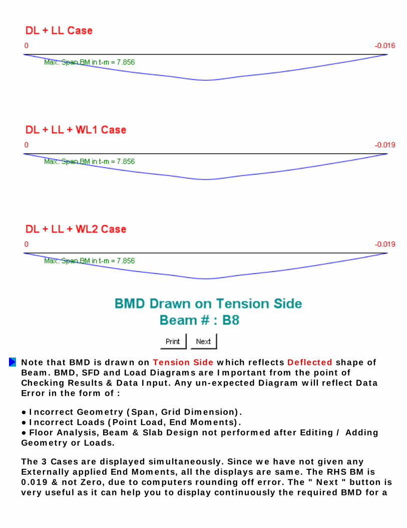
Note that BMD is drawn on Tension Side which reflects Deflected shape of Beam. BMD, SFD and Load Diagrams are Important from the point of Checking Results & Data Input. Any un-expected Diagram will reflect Data Error in the form of : ● Incorrect Geometry (Span, Grid Dimension). ● Incorrect Loads (Point Load, End Moments). ● Floor Analysis, Beam & Slab Design not performed after Editing / Adding Geometry or Loads. The 3 Cases are displayed simultaneously. Since we have not given any Externally applied End Moments, all the displays are same. The RHS BM is 0.019 & not Zero, due to computers rounding off error. The " Next " button is very useful as it can help you to display continuously the required BMD for a
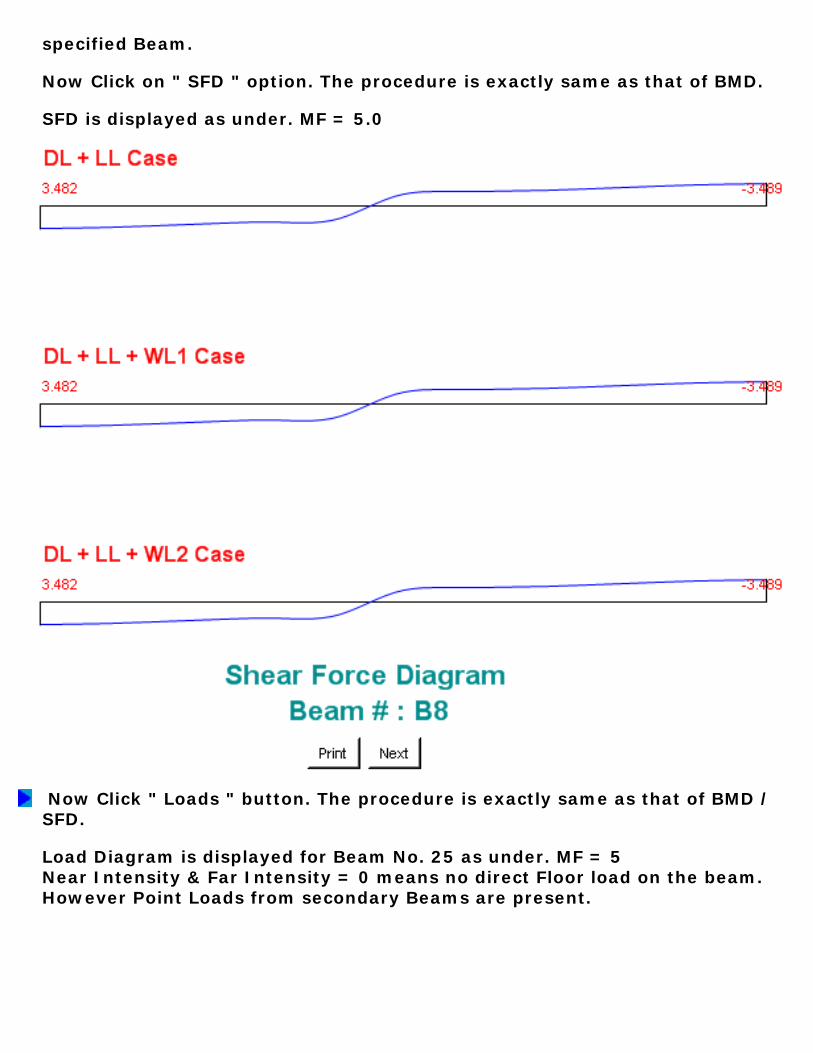
specified Beam. Now Click on " SFD " option. The procedure is exactly same as that of BMD. SFD is displayed as under. MF = 5.0
Now Click " Loads " button. The procedure is exactly same as that of BMD / SFD. Load Diagram is displayed for Beam No. 25 as under. MF = 5 Near Intensity & Far Intensity = 0 means no direct Floor load on the beam. However Point Loads from secondary Beams are present.
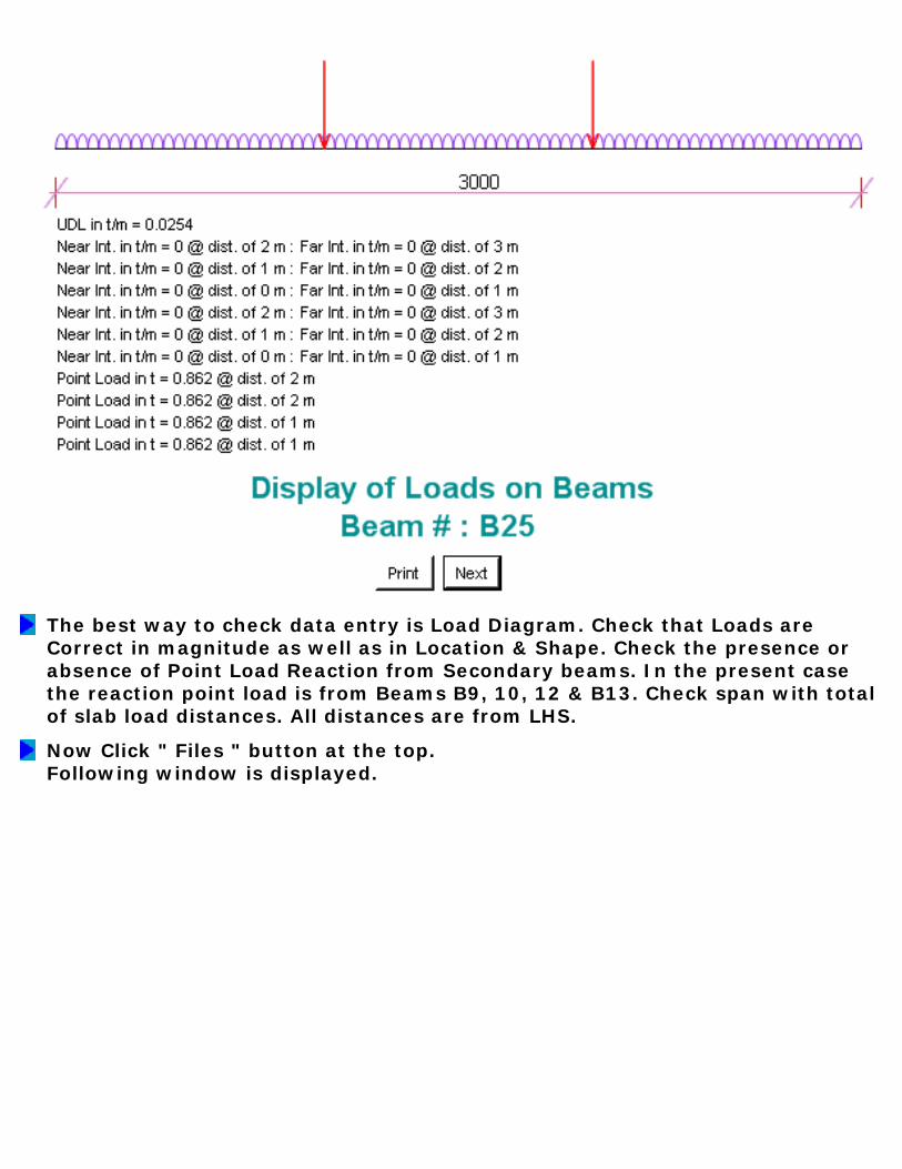
The best way to check data entry is Load Diagram. Check that Loads are Correct in magnitude as well as in Location & Shape. Check the presence or absence of Point Load Reaction from Secondary beams. In the present case the reaction point load is from Beams B9, 10, 12 & B13. Check span with total of slab load distances. All distances are from LHS.
Now Click " Files " button at the top. Following window is displayed.

Here we have 2 menus, one for Floor file and another for Column Project File. Use " For Floor Files Only " option to Copy, Delete & Move / Re-Name Floor Files. Now we will copy Example_1 file to Example_2 file. Click " Source " Button & select Eample_1 File from the file Dialogue Box. Again Click " Destination " Button & select Eample_2 File from the file Dialogue Box. Click " Copy " button. Following Window is displayed.
Similarly we can use Delete Option to Delete Files, however note that there will be no " Destination " file & destination text box shall be empty. Note that Floor File extension is " .SSF ", while Column Project File Extension is " .DAT ". The Column-Foundation File menu is similar to Floor File Menu, only difference is File extension. Hence Use " For Column " option to Copy, Delete & Move / Re-Name Column and Foundation Files. Now we have come to the end of Step # 12.
STEP NO. 12 IS OVER.
LEARN SSF STEP BY STEP STEP 13 : CREATION OF FLOOR PLAN IN AUTOCAD
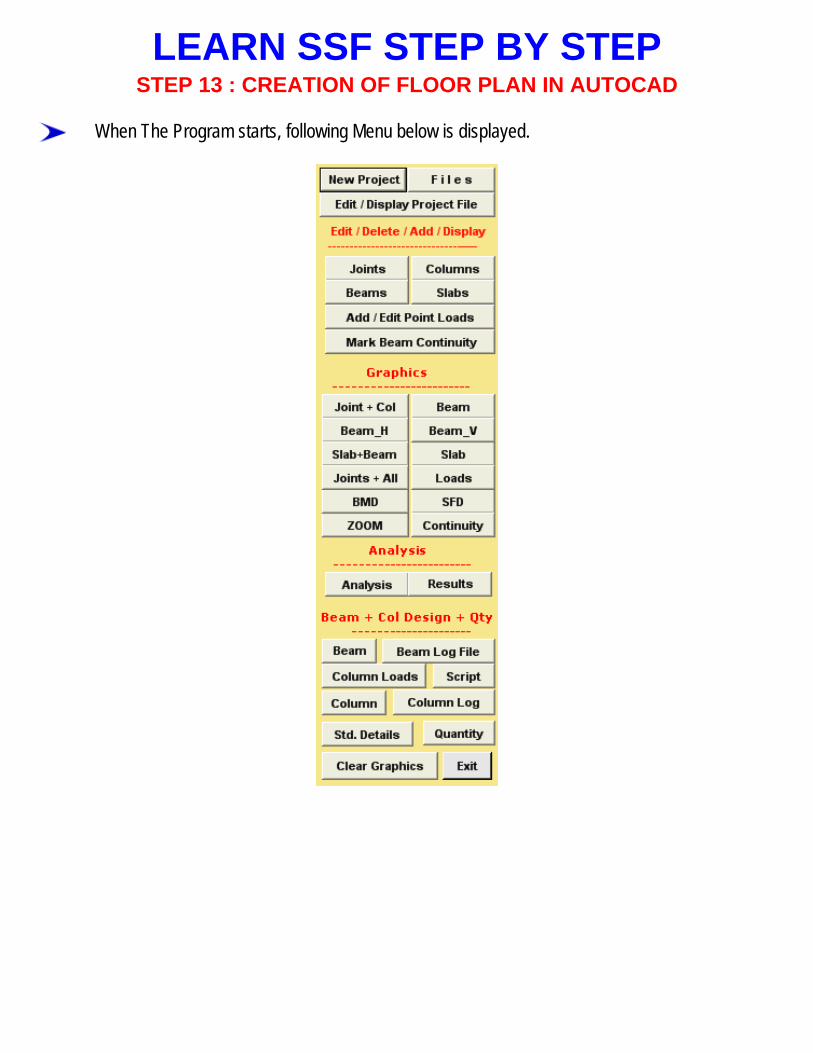
When The Program starts, following Menu below is displayed.
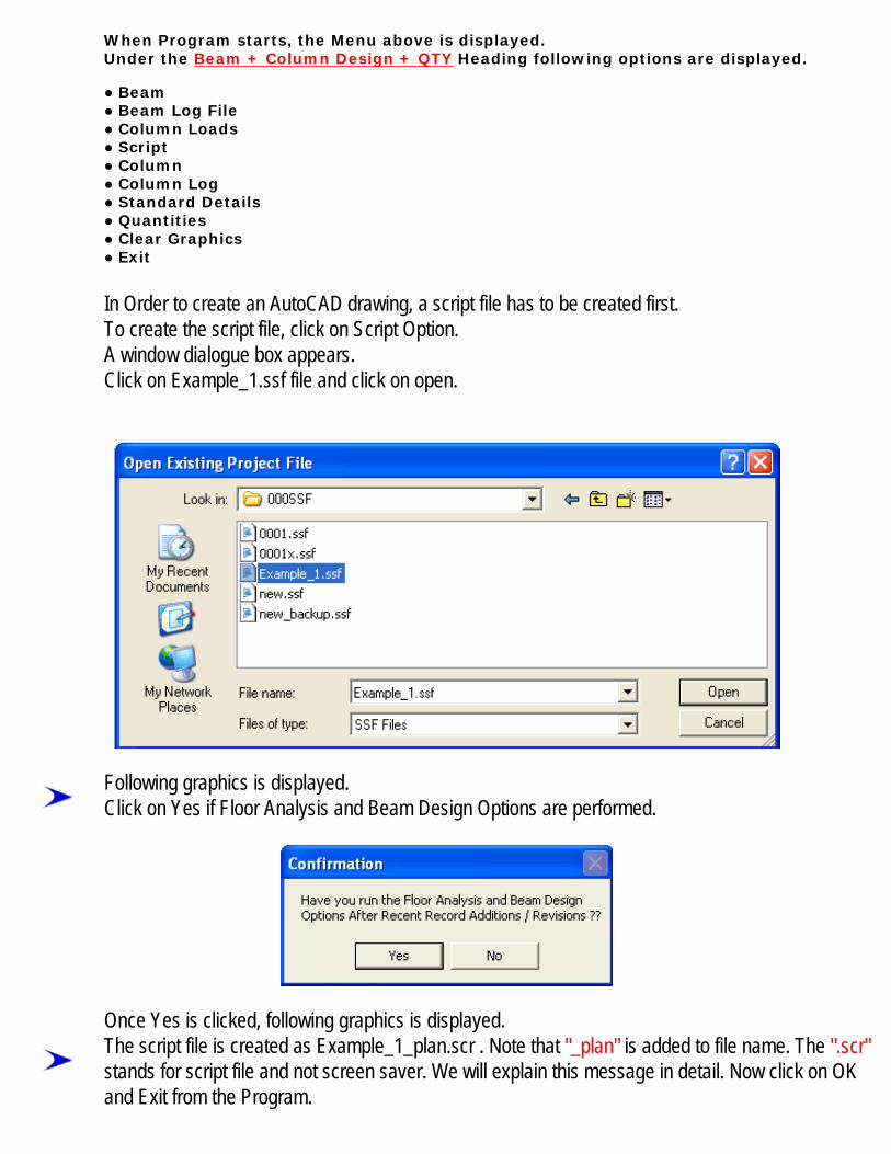
When Program starts, the Menu above is displayed. Under the Beam + Column Design + QTY Heading following options are displayed. ● Beam ● Beam Log File ● Column Loads ● Script ● Column ● Column Log ● Standard Details ● Quantities ● Clear Graphics ● Exit In Order to create an AutoCAD drawing, a script file has to be created first. To create the script file, click on Script Option. A window dialogue box appears. Click on Example_1.ssf file and click on open.
Following graphics is displayed. Click on Yes if Floor Analysis and Beam Design Options are performed.
Once Yes is clicked, following graphics is displayed. The script file is created as Example_1_plan.scr . Note that "_plan" is added to file name. The ".scr" stands for script file and not screen saver. We will explain this message in detail. Now click on OK and Exit from the Program.
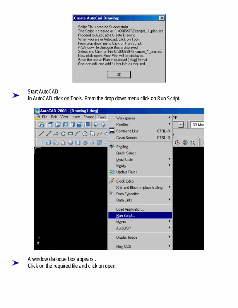
Start AutoCAD. In AutoCAD click on Tools. From the drop down menu click on Run Script.
A window dialogue box appears . Click on the required file and click on open.
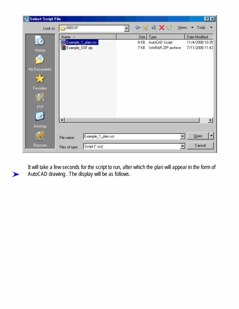
It will take a few seconds for the script to run, after which the plan will appear in the form of AutoCAD drawing . The display will be as follows.

Please note that the above drawing is Editable in AutoCAD.

The above drawing is drawn in the following layers , they are 1) Beam : Denotes beam 2) BeamCen : Denotes center line of the beam 3) Beamtext : Denotes text for beam 4) Column : Denotes Columns 5) Columntext : Denotes text for columns 6) Grids : Denotes dimensions 7) Slabtext : Denotes text for Slab 8) Border : For Web Thickness The layers can be turned Off/On at any time for convenience. just go to format option and click on layer from the drop down menu. Save the above Drawing in AutoCAD i.e. (.dwg) format.
STEP NO. 13 IS OVER.

LEARN SSF STEP BY STEPSTEP NO. 14 : Design of Building Columns
When Program starts, the Menu above is displayed. Under the Beam + Column Design + QTY Heading following options are displayed. ● Beam ● Beam Log File ● Column Loads ● Script ● Column ● Column Log ● Standard Details ● Quantities ● Clear Graphics ● Exit Now Click on " Column " Option. Following Important Message is displayed.
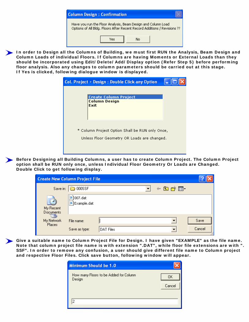
In order to Design all the Columns of Building, we must first RUN the Analysis, Beam Design and Column Loads of individual Floors. If Columns are having Moments or External Loads than they should be incorporated using Edit/Delete/Add/Display option (Refer Step 5) before performing floor analysis. Also any changes to column parameters should be carried out at this stage. If Yes is clicked, following dialogue window is displayed.
Before Designing all Building Columns, a user has to create Column Project. The Column Project option shall be RUN only once, unless Individual Floor Geometry Or Loads are Changed. Double Click to get following display.
Give a suitable name to Column Project File for Design. I have given "EXAMPLE" as the file name. Note that column project file name is with extension ".DAT", while floor file extensions are with ".SSF". In order to remove any confusion, a user should give different file name to Column project and respective Floor Files. Click save button, following window will appear.
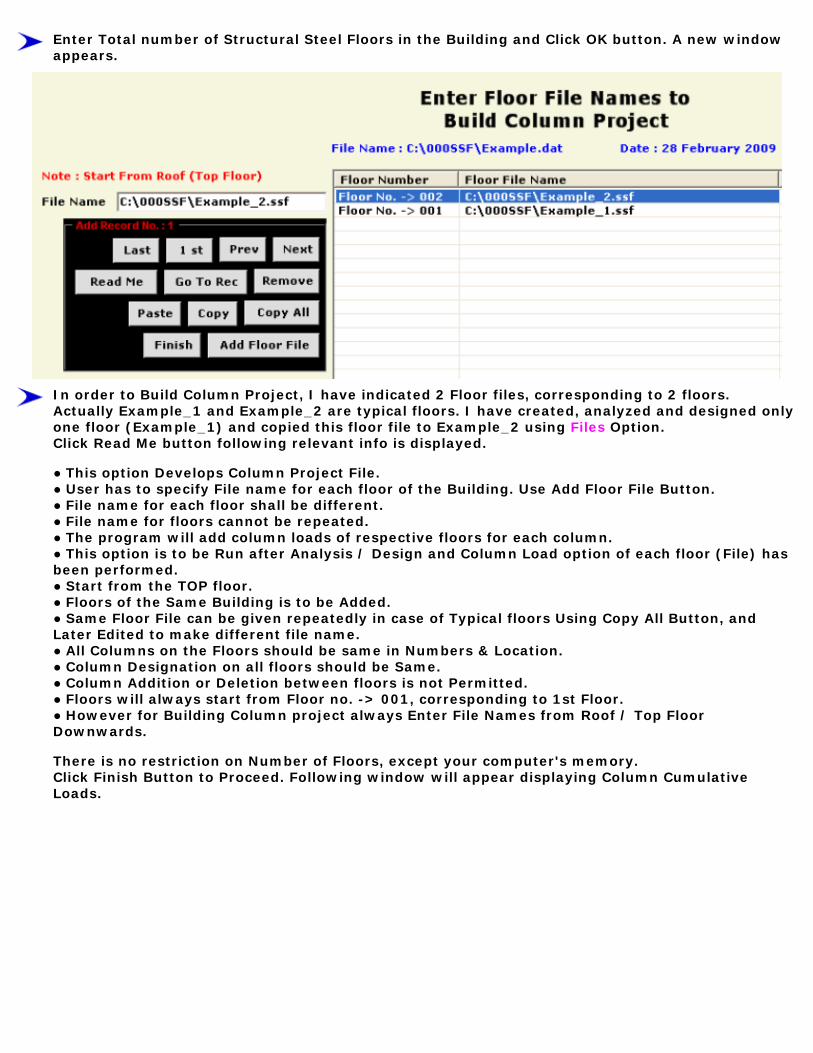
Enter Total number of Structural Steel Floors in the Building and Click OK button. A new window appears.
In order to Build Column Project, I have indicated 2 Floor files, corresponding to 2 floors. Actually Example_1 and Example_2 are typical floors. I have created, analyzed and designed only one floor (Example_1) and copied this floor file to Example_2 using Files Option. Click Read Me button following relevant info is displayed. ● This option Develops Column Project File. ● User has to specify File name for each floor of the Building. Use Add Floor File Button. ● File name for each floor shall be different. ● File name for floors cannot be repeated. ● The program will add column loads of respective floors for each column. ● This option is to be Run after Analysis / Design and Column Load option of each floor (File) has been performed. ● Start from the TOP floor. ● Floors of the Same Building is to be Added. ● Same Floor File can be given repeatedly in case of Typical floors Using Copy All Button, and Later Edited to make different file name. ● All Columns on the Floors should be same in Numbers & Location. ● Column Designation on all floors should be Same. ● Column Addition or Deletion between floors is not Permitted. ● Floors will always start from Floor no. -> 001, corresponding to 1st Floor. ● However for Building Column project always Enter File Names from Roof / Top Floor Downwards. There is no restriction on Number of Floors, except your computer's memory. Click Finish Button to Proceed. Following window will appear displaying Column Cumulative Loads.

Click OK button, Following message is displayed.
Now Double Click Column Design Option. Following message is displayed.
Just Like Beam Design, the Column Design Results (Safe / Un-Safe) are stored in Log File. If you click the Column Log File Button, various parameters on which Column Section is evaluated is displayed. User should study each parameter in order to redesign the Column for safety or for Economy / Optimization. Double Click Exit to leave Column Option.
Note that Unless all Beams and Columns Designs are Safe there is no Use of Proceeding to Column and Total Building Quantities and Costs.
STEP NO. 14 IS OVER.

LEARN SSF STEP BY STEPSTEP NO. 15 : Column and Project
Quantities And Cost
When Program starts, the Menu above is displayed. Under the Beam + Column Design + QTY Heading following options are displayed. ● Beam ● Beam Log File ● Column Loads ● Script ● Column ● Column Log ● Standard Details ● Quantities ● Clear Graphics ● Exit Now Click on " Quantity " Option. Following Message is displayed.

Now Double Click " Column Project " Option. Following Graphics is displayed. (Quantities and Cost of Floor beams + Slabs are already Covered in Step 11).
Unless All relevant Floors of the Building are Analyzed and Beam and Columns are Designed, Column Loads worked out, the Calculation of Quantities & Cost have no meaning. The Quantity Option is to be RUN last after all other things are completed. Click Yes if complied. Select Your Project File from Window Dialogue Box (Example.Dat in My case) & Click Open. Following Graphics is Displayed.
Click OK to Exit. Now Double Click " Total Project " Option. Select your File from Window Dialogue Box & Click Open. Following Graphics is displayed.

This Completes Learning Steps.
STEP NO. 15 IS OVER.

OTHER SOFTWARES: SUPER CIVIL CD - Single Point Solution To Your Civil Engineering Needs SUPER RATE ANALYSIS - Rate Analysis Of 1299 Nos. Of Civil Engineering Items 2D FRAME ANALYSIS - Discover The Beauty Of Structural Analysis R C F ‐ A Software for Analysis, Design, Estimation & Costing of RCC Floors Q T Y - Quantity Estimation & Cost, Project Control SUPER REAL VALUATION - A Software For Immovable Properties ROADS - Pavement Design & Rate Analysis Of Road Items ROAD ESTIMATE - Quantity Estimation & Cost, Project Control For Road ELECTRIC COST - Costing, Project Control & MDS For Electrical Projects HVAC COST - Costing, Project Control & Design For HVAC Engineers BILLING JI - A Database Management Software For General Billing RA BILL - A Database Management Software For Item Rate Contract Billing BUILDERS BILL - A Database Management Software for Billing of Lump sum Contracts BID ANALYSIS - A Software For Technical & Commercial Tender Analysis RAFT FOUNDATION - Analysis, Design, Estimation, Costing & Drawing of RCC Raft Foundation STEEL_2007 - Limit State design of Steel as per IS 800 : 2007 SITE CONTROL - A Management Software for Resource Control At Site. DESIGN & DRAWING CONTROL - A DBM Software for Control of Design & Drawing Manhours. COMPOSITE - A Software for Analysis, Design, Costing & Drawing of Composite Floor Buildings INSTA COST - A Software for Estimating Project Cost & Tender SOQ Instantly FLAT SLAB - A Software for Analysis, Design, Estimation, Costing & Drawings of Flat Slabs FLAT RAFT - A Software for Analysis, Design, Estimation, Costing & Drawings of Rigid RCC Flat Rafts OPTIMIZE_BAR - A Software for Optimization of Reinforcements from Existing Bar Bending Schedule OPTIMIZE_STEEL - A Software for Optimization of Steel Sections from Existing Fabrication Drawing AutoQty - A Software for Automatic Quantity & Cost Estimation from AutoCAD Drawings