leak testing device manual - becker maschinenbau · electric motor may be defective and should be...
TRANSCRIPT
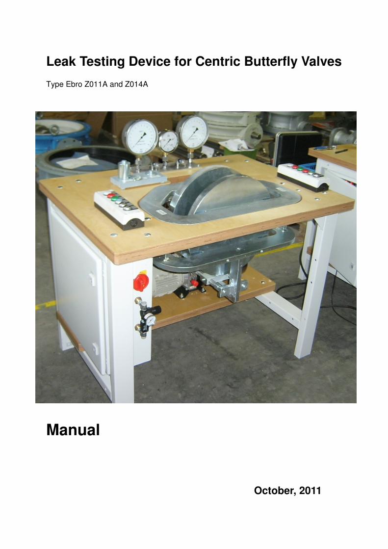
Leak Testing Device for Centric Butterfly Valves Type Ebro Z011A and Z014A
Manual
October, 2011
2
Contents 1. Description of Device Page 3 2. Installation and Installation Requirements Page 3 3. Taking in Use Page 4 4. Testing of Valves Page 4-5 5. Maintenance Page 5 6. Pneumatic Diagram and Part List Page 6-7 7. Hydraulic Diagram and Part List Page 8-9 8. Electrical Diagram and Part List Page 10-11 9. Press Frame 125 Assembly and Part List Page 12-13 10. Press Frame 200 Assembly and Part List Page 14-15 11. Press Frame 300 Assembly and Part List Page16-17 12. Dimensions Page 18 13. Pressure.Gauge Unit Page 19-20 14. Calibration Page 20 15. Technical Data Page 21 16. Auxiliary Views Page 22-23 17. Declaration of Conformity Page 24 Manufacturer and Supplier: Becker Maschinenbau Handelsriege 18 58339 Breckerfeld Germany Web: www.becker-maschinenbau.com Mail: [email protected]
3
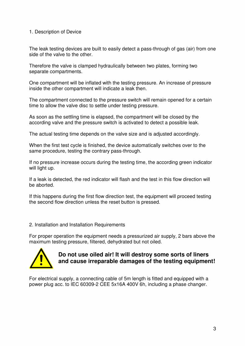
1. Description of Device The leak testing devices are built to easily detect a pass-through of gas (air) from one side of the valve to the other. Therefore the valve is clamped hydraulically between two plates, forming two separate compartments. One compartment will be inflated with the testing pressure. An increase of pressure inside the other compartment will indicate a leak then. The compartment connected to the pressure switch will remain opened for a certain time to allow the valve disc to settle under testing pressure. As soon as the settling time is elapsed, the compartment will be closed by the according valve and the pressure switch is activated to detect a possible leak. The actual testing time depends on the valve size and is adjusted accordingly. When the first test cycle is finished, the device automatically switches over to the same procedure, testing the contrary pass-through. If no pressure increase occurs during the testing time, the according green indicator will light up. If a leak is detected, the red indicator will flash and the test in this flow direction will be aborted. If this happens during the first flow direction test, the equipment will proceed testing the second flow direction unless the reset button is pressed. 2. Installation and Installation Requirements For proper operation the equipment needs a pressurized air supply, 2 bars above the maximum testing pressure, filtered, dehydrated but not oiled.
Do not use oiled air! It will destroy some sorts of liners and cause irreparable damages of the testing equipment!
For electrical supply, a connecting cable of 5m length is fitted and equipped with a power plug acc. to IEC 60309-2 CEE 5x16A 400V 6h, including a phase changer.

4
3. Taking in Use For reasons of transportation, the equipment is delivered with empty hydraulic set. First fill in approx. 5 litres of suitable hydraulic fluid such as HLP mineral oil. Check oil level at the gauge of the fill-plug. For further information look at separate documentation “Hydropa Hydraulic Device KL-1-B-ZP1,2-BH06-EDJ(0,75)/1-ZT7-DB1/300(200)-H1” on attached CD. Connect the device to the mains and switch on mains switch. (Refer to chapter 4.) Check correct direction of rotation of hydraulic pump by pressing both chuck keys. After a few seconds, the cylinder should move forward. If not, disconnect the plug and Change two mains phases, using the phase changer of the plug: CEE plug with phase changer:
Depress the changer with a suitable screwdriver and turn 180°
Now the cylinder moves forward while depressing the chuck keys. Insert a suitable distance and an according butterfly valve and depress the chuck keys to chuck the valve. Release and chuck again for several times to get rid of the air remaining in the hydraulic system. Connect to compressed air supply. Incoming pressure must be 2bars above testing pressure. The device is ready for use now! 4. Testing of Valves First make sure, compressed air supply is connected. Check the testing pressure at the gauge and adjust it to the required value. After switching on the mains switch a self-test routine will start, indicated by all indicator lights flashing four times. When this routine is finished, both the white test indicators will light up permanently. Chose a spacer according to the valve size, insert it into the centring device and place the valve to be tested on top of the spacer between the pressure plates.
Make sure, the valve is safely seated on top of the spacer! The pivot of the spacer must properly fit into the end plug of the valve! The valve must not be tilt or inclined!

5
Press both of the chuck buttons for approx. 5 seconds until the valve is safely clamped. The actual hydraulic pressure is displayed on the middle gauge. It has to be around 200bar. Start the testing procedure by depressing the start button once. The first chamber will be tested as described above. The according white indicator will flash, showing the test is running. The actual testing pressure can be taken from the according gauge, right respectivly left. After the first chamber test is finished, the result indicator will light up. After 5 seconds the device will automatically switch over to the reverse test, flashing the other white indicator. The test run can be terminated at every stage by actuating the reset button. As soon as the complete test is finished and the valve passed the test, both the green indicators will be lit. If a red indicator is flashing, the according flow direction of the valve failed the test. Press reset to terminate the test. The system will be depressurized for 15 seconds, but the valve can already be released by pressing the release button. Take off the valve. When the white indicators are lit again, the system is ready for the next test cycle.
The hydraulic pump only works, if both the chuck buttons are depressed simultaneously within half a second. If a loss of compressed air can be heard during the test, the pump can be actuated to increase the clamp force, but the release button is blocked while testing.
5. Maintenance Keep the installation tidy. Pay attention the air preparation unit the testing device is connected to. Dewater and change filter frequently. Change hydraulic fluid at least once a year. Place a suitable bin containing 10 litres underneath the drain plug and remove the plug. Remove the fill plug and drain oil completely. Refit the drain plug and proceed as described above (Chapter 3. Taking in Use). If the red service indicator is lit, open the switch cabinet and reset the motor overload switch.
If the overload switch triggers too often, i.e. more than once a week, the electric motor may be defective and should be checked by an electrician!

6
6. Pneumatic Diagram and Part List
7
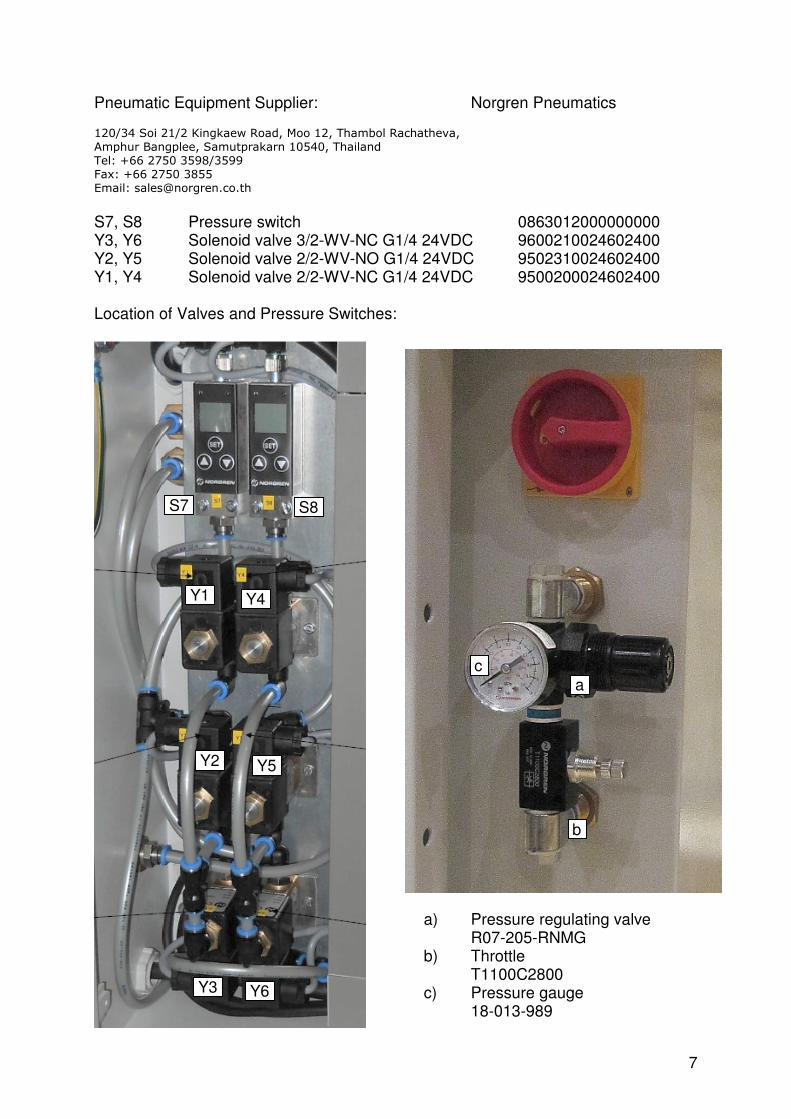
Pneumatic Equipment Supplier: Norgren Pneumatics
120/34 Soi 21/2 Kingkaew Road, Moo 12, Thambol Rachatheva,
Amphur Bangplee, Samutprakarn 10540, Thailand
Tel: +66 2750 3598/3599
Fax: +66 2750 3855
Email: [email protected]
S7, S8 Pressure switch 0863012000000000 Y3, Y6 Solenoid valve 3/2-WV-NC G1/4 24VDC 9600210024602400 Y2, Y5 Solenoid valve 2/2-WV-NO G1/4 24VDC 9502310024602400 Y1, Y4 Solenoid valve 2/2-WV-NC G1/4 24VDC 9500200024602400 Location of Valves and Pressure Switches:
a) Pressure regulating valve R07-205-RNMG
b) Throttle T1100C2800
c) Pressure gauge 18-013-989
a
c
b
S8
Y3 Y6
Y5 Y2
Y4 Y1
S7
8
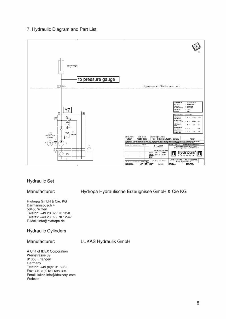
7. Hydraulic Diagram and Part List Hydraulic Set Manufacturer: Hydropa Hydraulische Erzeugnisse GmbH & Cie KG
Hydropa GmbH & Cie. KG Därmannsbusch 4 58456 Witten Telefon: +49 23 02 / 70 12-0 Telefax: +49 23 02 / 70 12-47 E-Mail: [email protected]
Hydraulic Cylinders
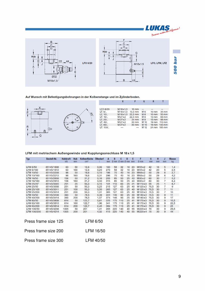
Manufacturer: LUKAS Hydraulik GmbH
A Unit of IDEX Corporation Weinstrasse 39 91058 Erlangen Germany Telefon: +49 (0)9131 698-0 Fax: +49 (0)9131 698-394 Email: [email protected] Website: http://www.lukas.dewww.lukas.de
to pressure gauge
Y7
9
Press frame size 125 LFM 6/50 Press frame size 200 LFM 16/50 Press frame size 300 LFM 40/50
10
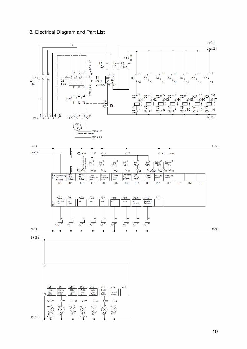
8. Electrical Diagram and Part List
11
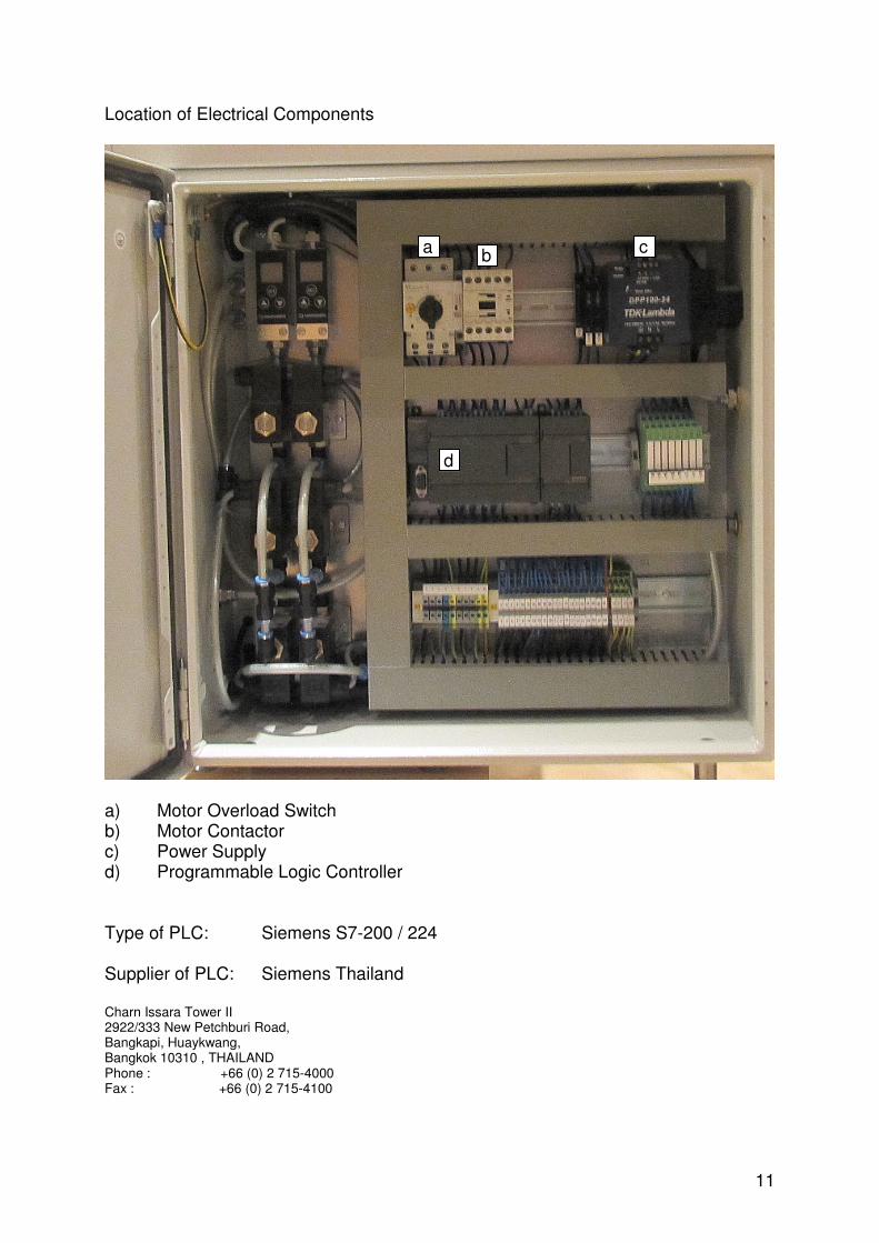
Location of Electrical Components
a) Motor Overload Switch b) Motor Contactor c) Power Supply d) Programmable Logic Controller Type of PLC: Siemens S7-200 / 224 Supplier of PLC: Siemens Thailand Charn Issara Tower II 2922/333 New Petchburi Road, Bangkapi, Huaykwang, Bangkok 10310 , THAILAND Phone : +66 (0) 2 715-4000 Fax : +66 (0) 2 715-4100
d
c b
a
12
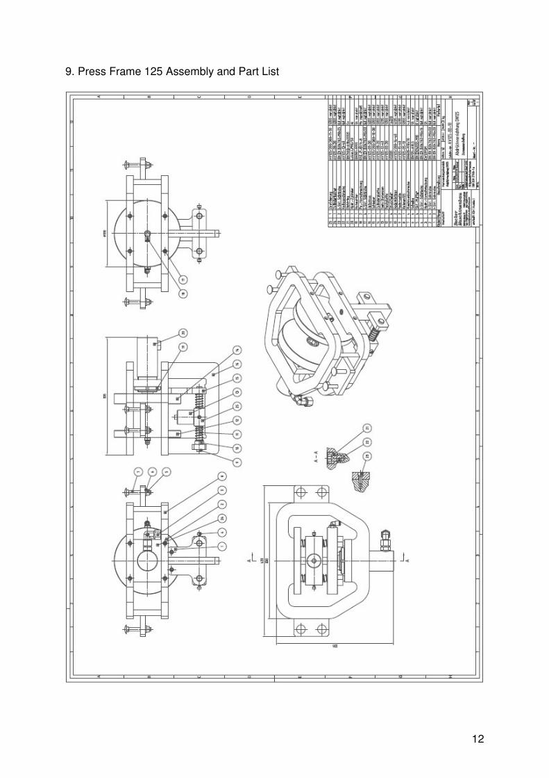
9. Press Frame 125 Assembly and Part List
13
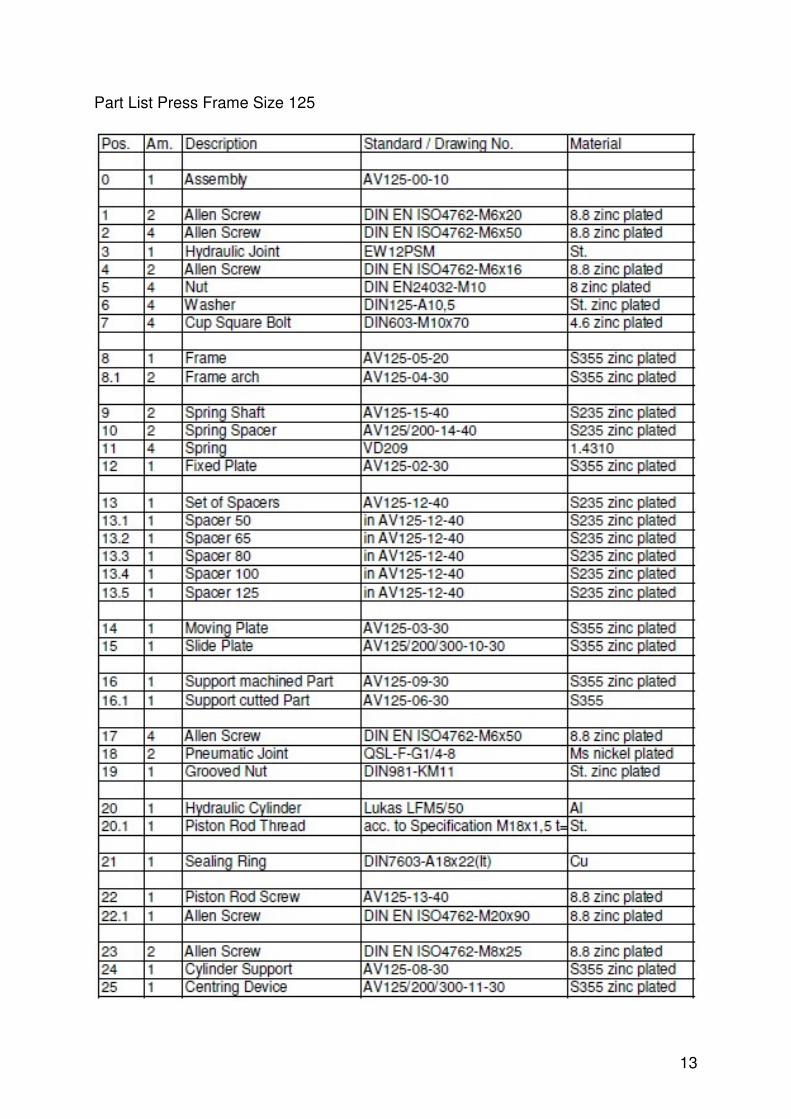
Part List Press Frame Size 125
14
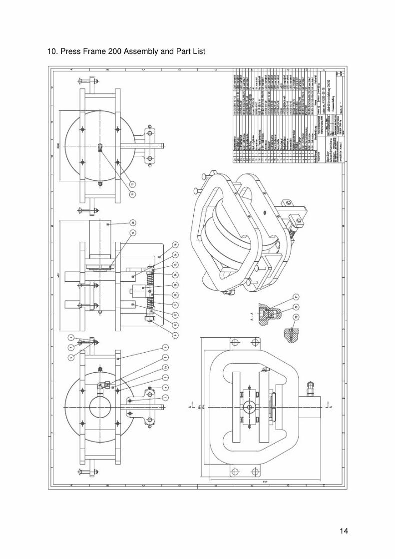
10. Press Frame 200 Assembly and Part List

15
Part List Press Frame Size 200
16
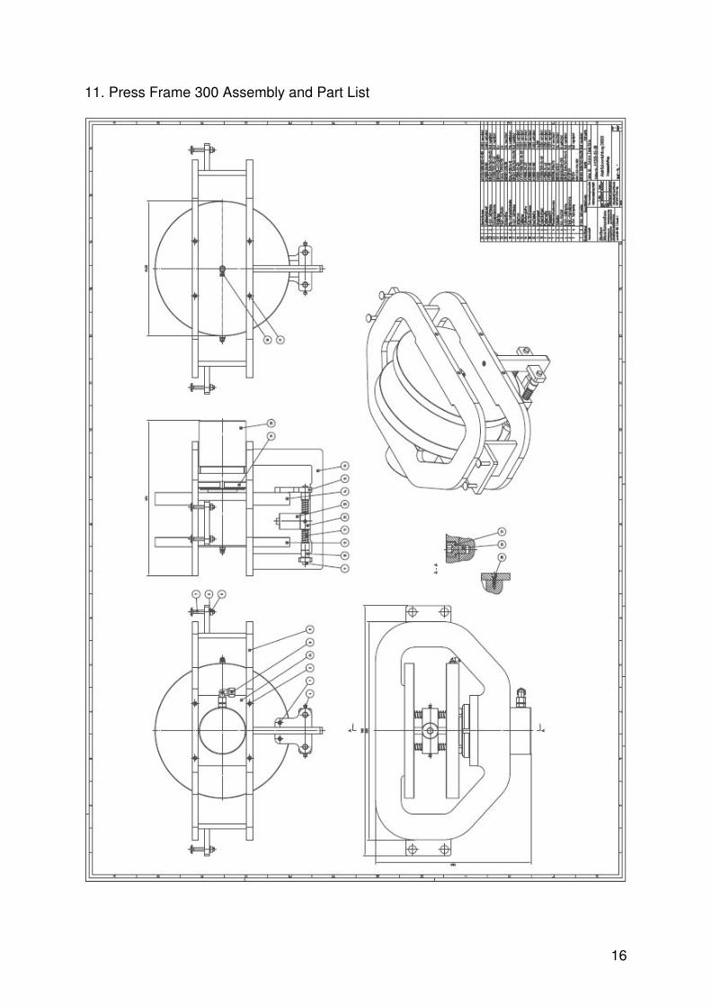
11. Press Frame 300 Assembly and Part List
17
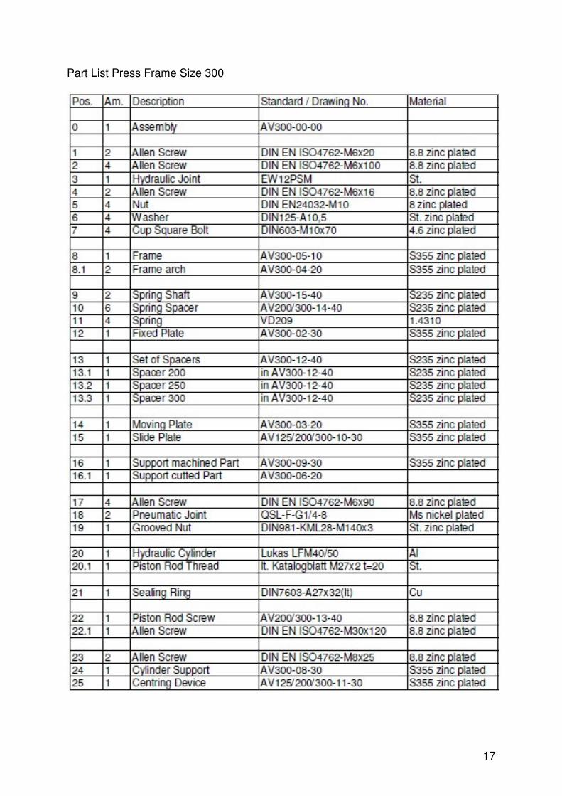
Part List Press Frame Size 300

18
12. Dimensions Dimensions of Testing Benches Dimensions of Spacers Size 125 Size 200 Size 300
19
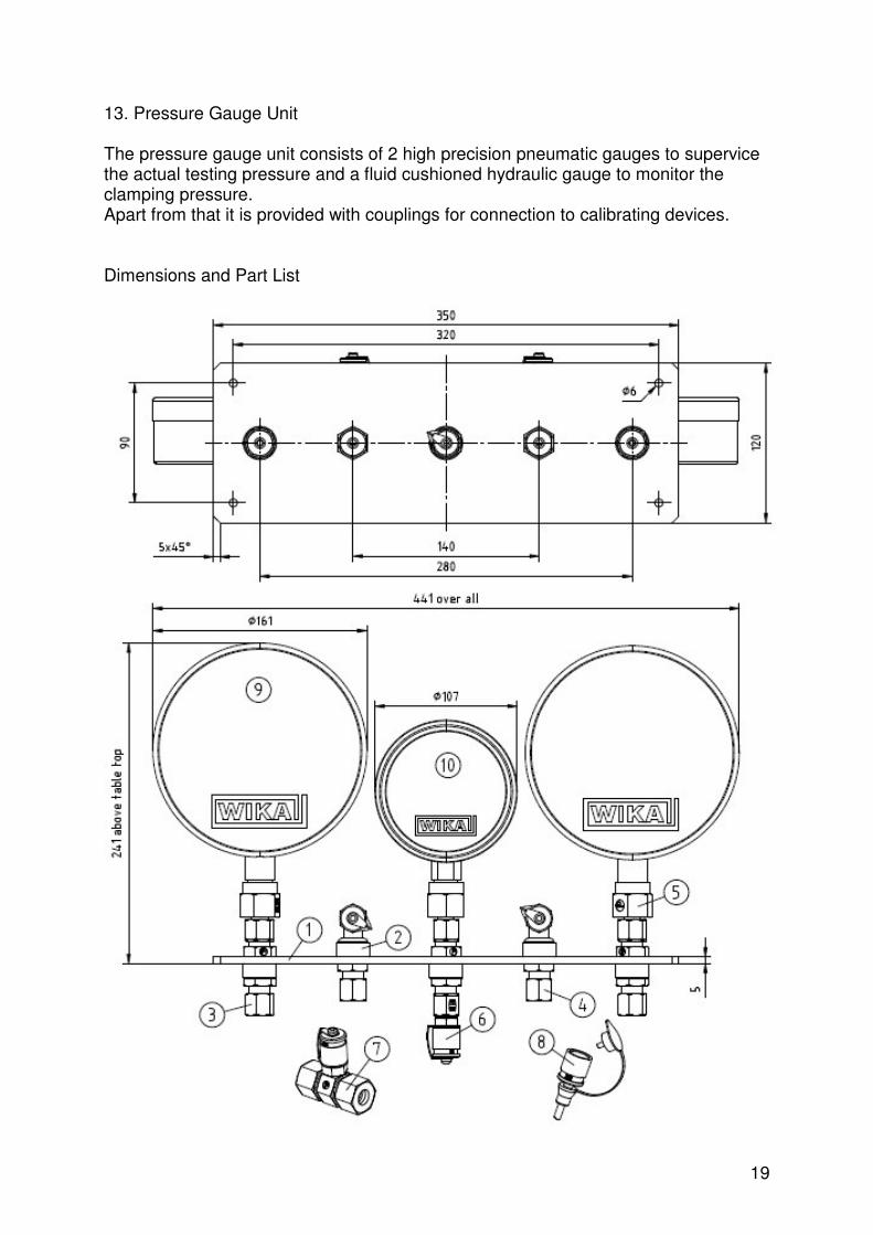
13. Pressure Gauge Unit The pressure gauge unit consists of 2 high precision pneumatic gauges to supervice the actual testing pressure and a fluid cushioned hydraulic gauge to monitor the clamping pressure. Apart from that it is provided with couplings for connection to calibrating devices. Dimensions and Part List

20
Part List
Supplier of Gauges:
Wika Instrumentation Corporation (Thailand) Co., Ltd.
850/7 Ladkrabang Road, Ladkrabang Bangkok 10520
Phone: +66 2 326 6876-80 Fax: +66 2 326 6874 E-mail: [email protected]
http://www.wika.co.th
14. Calibration The units are precalibrated and ready for use. If nessecary, verification can be done by using a calibrated leak. If there is need for that, please contact the quality management of EBRO – Valves Germany and ask for further instructions.
21
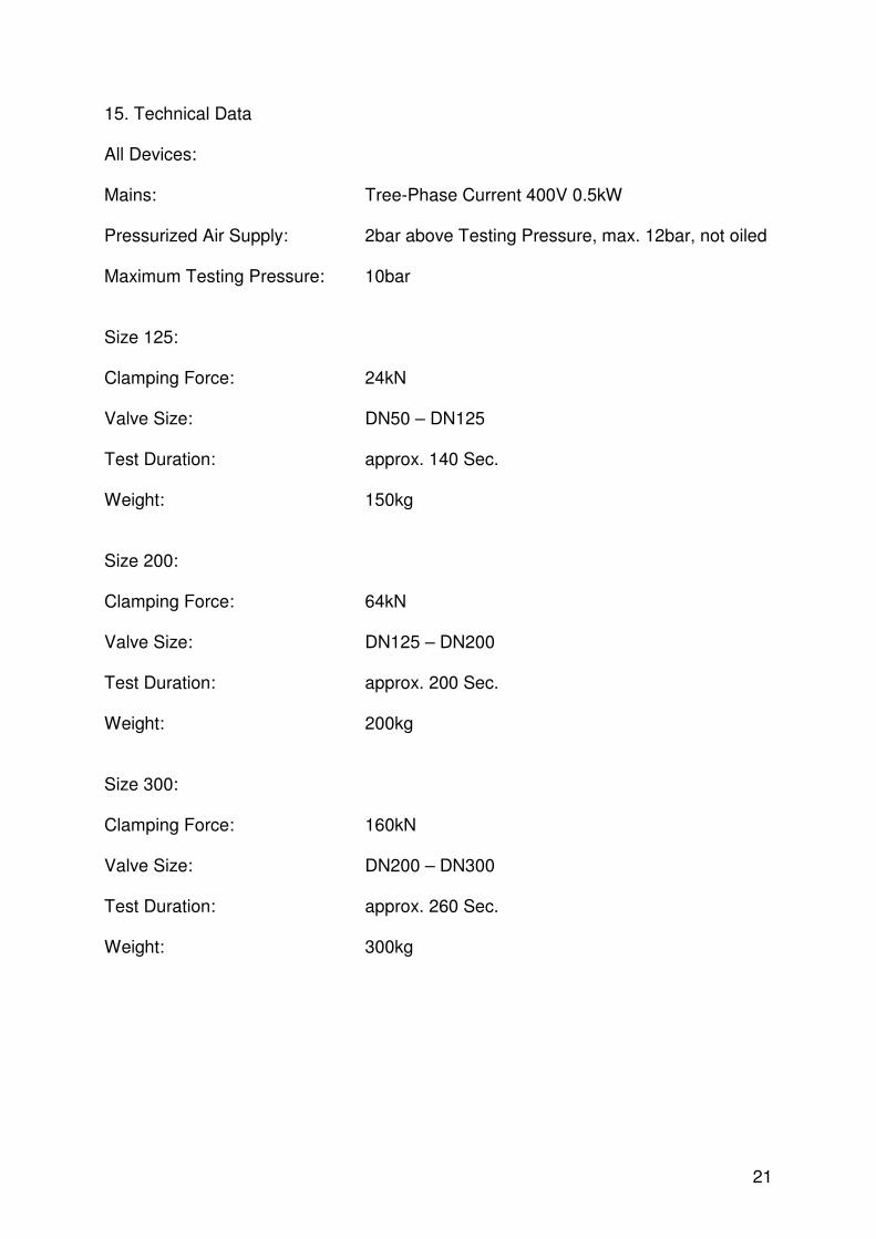
15. Technical Data All Devices: Mains: Tree-Phase Current 400V 0.5kW Pressurized Air Supply: 2bar above Testing Pressure, max. 12bar, not oiled Maximum Testing Pressure: 10bar Size 125: Clamping Force: 24kN Valve Size: DN50 – DN125 Test Duration: approx. 140 Sec. Weight: 150kg Size 200: Clamping Force: 64kN Valve Size: DN125 – DN200 Test Duration: approx. 200 Sec. Weight: 200kg Size 300: Clamping Force: 160kN Valve Size: DN200 – DN300 Test Duration: approx. 260 Sec. Weight: 300kg

22
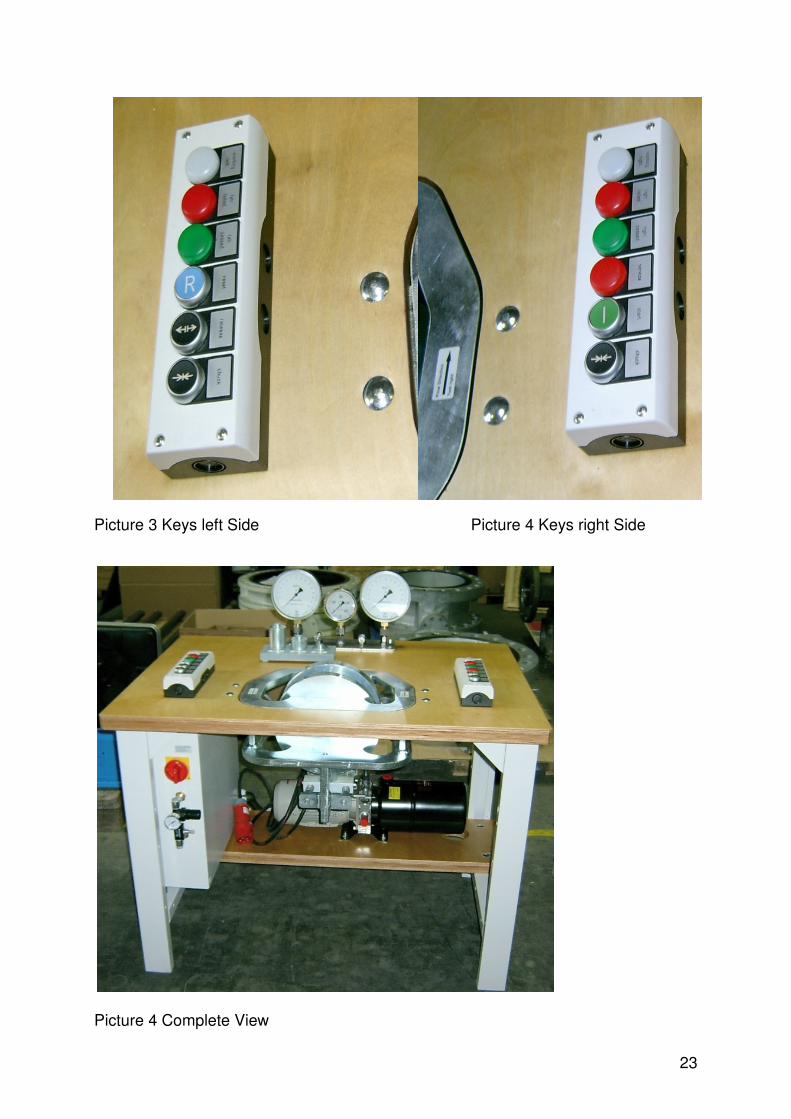
16. Auxiliary Views Picture 1 Table Top Picture 2 Hydro Set and Fluid connectors
23
Picture 3 Keys left Side Picture 4 Keys right Side Picture 4 Complete View
24
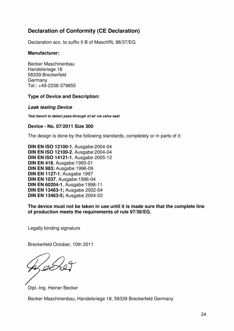
Declaration of Conformity (CE Declaration) Declaration acc. to suffix II B of MaschRL 98/37/EG Manufacturer: Becker Maschinenbau Handelsriege 18 58339 Breckerfeld Germany Tel.: +49-2338-379855 Type of Device and Description: Leak testing Device
Test bench to detect pass-through of air via valve seat
Device - No. 07/2011 Size 300
The design is done by the following standards, completely or in parts of it: DIN EN ISO 12100-1, Ausgabe:2004-04 DIN EN ISO 12100-2, Ausgabe:2004-04 DIN EN ISO 14121-1, Ausgabe 2005-12 DIN EN 418, Ausgabe:1993-01 DIN EN 983; Ausgabe 1996-09 DIN EN 1127-1; Ausgabe 1997 DIN EN 1037, Ausgabe:1996-04 DIN EN 60204-1, Ausgabe:1998-11 DIN EN 13463-1; Ausgabe 2002-04 DIN EN 13463-5; Ausgabe 2004-03 The device must not be taken in use until it is made sure that the complete line of production meets the requirements of rule 97/38/EG. Legally binding signature Breckerfeld October, 10th 2011 Dipl.-Ing. Heiner Becker Becker Maschinenbau, Handelsriege 18, 58339 Breckerfeld Germany