leak detection and repair - united states environmental ... · leak detection and repair compliance...
TRANSCRIPT
Leak Detection and Repair
A Best Practices Guide
United States
Environmental Protection Agency
Office of Compliance
Office of Enforcement and Compliance Assurance
1200 Pennsylvania Avenue, NW
(mail code)
Washington, DC 20460

Disclaimer
The U.S. Environmental Protection Agency (EPA) has reviewed this document and approves it for publication. This
document does not constitute rulemaking by the EPA and may not be relied on to create a substantive or procedural right
or benefit enforceable at law or in equity, by any person. The EPA may take actions at variance with this document and its
internal procedures.


Contents
1.0 Purpose . . . . . . . . . . . . . . . . . . . . . . . . . . . . . . . . . . . . . . . . . . . . . . . . . . . 1
2.0 Why Regulate Equipment Leaks?. . . . . . . . . . . . . . . . . . . . . . . . . . . . . . . . . . 2
3.0 Sources, Causes And Control Of Equipment Leaks . . . . . . . . . . . . . . . . . . . . . 3
3.1 How are emissions from equipment leaks reduced? . . . . . . . . . . . . . . . 3
3.2 What regulations incorporate LDAR programs? . . . . . . . . . . . . . . . . . . . 6
4.0 What Are the Benefits of an LDAR Program? . . . . . . . . . . . . . . . . . . . . . . . . . . 7
4.1 Reducing Product Losses . . . . . . . . . . . . . . . . . . . . . . . . . . . . . . . . . . 8
4.2 Increasing Safety for Facility Workers and Operators . . . . . . . . . . . . . . . 8
4.3 Decreasing Exposure for the Surrounding Community . . . . . . . . . . . . . . 8
4.4 Potentially Reducing Emission Fees . . . . . . . . . . . . . . . . . . . . . . . . . . 8
4.5 Avoiding Enforcement Actions . . . . . . . . . . . . . . . . . . . . . . . . . . . . . . 8
5.0 Elements of an LDAR Program . . . . . . . . . . . . . . . . . . . . . . . . . . . . . . . . . . . 9
6.0 What Compliance Problems Have Been Found With Current LDAR
Programs? . . . . . . . . . . . . . . . . . . . . . . . . . . . . . . . . . . . . . . . . . . . . . . . . . 15
7.0 Model LDAR Program . . . . . . . . . . . . . . . . . . . . . . . . . . . . . . . . . . . . . . . . . 19
7.1 Written LDAR Program . . . . . . . . . . . . . . . . . . . . . . . . . . . . . . . . . . . 20
7.2 Training . . . . . . . . . . . . . . . . . . . . . . . . . . . . . . . . . . . . . . . . . . . . . 20
7.3 LDAR Audits. . . . . . . . . . . . . . . . . . . . . . . . . . . . . . . . . . . . . . . . . . 21
7.4 Contractor Accountability . . . . . . . . . . . . . . . . . . . . . . . . . . . . . . . . . 22
7.5 Internal Leak Definition for Valves and Pumps . . . . . . . . . . . . . . . . . . 22
7.6 More Frequent Monitoring . . . . . . . . . . . . . . . . . . . . . . . . . . . . . . . . 23
7.7 Repairing Leaking Components. . . . . . . . . . . . . . . . . . . . . . . . . . . . . 23
7.8 Delay of Repair Compliance Assurance . . . . . . . . . . . . . . . . . . . . . . . 24
7.9 Electronic Monitoring and Storage of LDAR Data . . . . . . . . . . . . . . . . 24
7.10 QA/QC of LDAR Data . . . . . . . . . . . . . . . . . . . . . . . . . . . . . . . . . . . . 25
7.11 Calibration/Calibration Drift Assessment . . . . . . . . . . . . . . . . . . . . . . 25
7.12 Records Maintenance . . . . . . . . . . . . . . . . . . . . . . . . . . . . . . . . . . . 26
8.0 Sources of Additional Information . . . . . . . . . . . . . . . . . . . . . . . . . . . . . . . . 27

Tables
Table 3.1 Sources of equipment leaks. . . . . . . . . . . . . . . . . . . . . . . . . . . . . . . . 4
Table 3.2 Equipment component counts at a typical refinery or chemical plant. . . . 5
Table 3.3 Uncontrolled VOC emissions at a typical facility. . . . . . . . . . . . . . . . . . 5
Table 4.1 Control effectiveness for an LDAR program at a chemical process unit
and a refinery. . . . . . . . . . . . . . . . . . . . . . . . . . . . . . . . . . . . . . . . . . . 7
Leak Detection and Repair Compliance Assistance Guidance—A Best Practices Guide
Appendices
Appendix A Federal Regulations That Require a Formal LDAR Program
With Method 21 . . . . . . . . . . . . . . . . . . . . . . . . . . . . . . . . . . . . . . . 29
Appendix B Federal Regulations That Require the Use of Method 21
But Do Not Require a Formal LDAR Program . . . . . . . . . . . . . . . . . . . 30
Appendix C Method 21 General Procedure . . . . . . . . . . . . . . . . . . . . . . . . . . . . . 31
Appendix D Method 21—Determination of Volatile Organic Compound Leaks . . . . . 32
Appendix E Summary of NEIC Comparative Monitoring Results of
Leaking Valves at 17 Refineries . . . . . . . . . . . . . . . . . . . . . . . . . . . . 39
Appendix F Enforcement Alert . . . . . . . . . . . . . . . . . . . . . . . . . . . . . . . . . . . . . . 40

Leak Detection and Repair—A Best Practices Guide
1.0 Purpose
In general, EPA has found signifi cant widespread
noncompliance with Leak Detection and Repair
(LDAR) regulations and more specifi cally, noncom
pliance with Method 21 requirements. In 1999, EPA
estimated that, as a result of this noncompliance,
an additional 40,000 tons of VOCs are emitted an
nually from valves at petroleum refi neries alone.
This document is intended for use by regulated
entities as well as compliance inspectors to identify
some of the problems identified with LDAR pro
grams focusing in on Method 21 requirements and
describe the practices that can be used to increase
the effectiveness of an LDAR program. Specifi cally,
this document explains:
• The importance of regulating equipment
leaks;
• The major elements of an LDAR program;
• Typical mistakes made when monitoring to
detect leaks;
• Problems that occur from improper manage
ment of an LDAR program; and
• A set of best practices that can be used to
implement effective an LDAR program.
Some of the elements of a model LDAR program,
as described in Section 7.0, are required by current
Federal regulations. Other model LDAR program
elements help ensure continuous compliance al
though they may not be mandated from a regulato
ry standpoint. Furthermore, State or local require
ments may be more stringent than some elements
of the model LDAR program, such as with leak
definitions. Prior to developing a written LDAR
program plan, all applicable regulations should be
reviewed to determine and ensure compliance with
the most stringent requirements.
1
According to EPAs 2002 National Emissions
Inventory (NEI) database, 125,000 tons per year
(tpy) of VOC are emitted from petroleum refiner
ies. It is estimated that over 49,000 tpy of VOC
from refineries are equipment leak emissions.
Of the 165,000 tpy of VOC emissions from
chemical manufacturing facilities, 21,000 tpy is
attributable to equipment leaks.
Leak Detection and Repair—A Best Practices Guide
2.0 Why Regulate Equipment Leaks?
EPA has determined that leaking equipment, such
as valves, pumps, and connectors, are the largest
source of emissions of volatile organic compounds
(VOCs) and volatile hazardous air pollutants
(VHAPs) from petroleum refineries and chemical
manufacturing facilities. The Agency has estimated
that approximately 70,367 tons per year of VOCs
and 9,357 tons per year of HAPs have been emitted
from equipment leaks. Emissions from equipment
leaks exceed emissions from storage vessels, waste
water, transfer operations, or process vents.
VOCs contribute to the formation of ground-level
ozone. Ozone is a major component of smog, and
causes or aggravates respiratory disease, particu
larly in children, asthmatics, and healthy adults
who participate in moderate exercise. Many
areas of the United States, particularly those areas
where refineries and chemical facilities are located,
do not meet the National Ambient Air Quality
Standard (NAAQS) for ozone. Ozone can be trans
ported in the atmosphere and contribute to nonat
tainment in downwind areas.
Some species of VOCs are also classified as VHAPs.
Some known or suspected effects of exposure to
VHAPs include cancer, reproductive eff ects, and
birth defects. The highest concentrations of VHAPs
tend to be closest to the emission source, where
the highest public exposure levels are also often
detected. Some common VHAPs emitted from re
fineries and chemical plants include acetaldehyde,
benzene, formaldehyde, methylene chloride, naph
thalene, toluene, and xylene.
’
-
2

Leak Detection and Repair—A Best Practices Guide
3.0 Sources, Causes And Control Of Equipment Leaks
A typical refinery or chemical plant can emit 600
700 tons per year of VOCs from leaking equipment,
such as valves, connectors, pumps, sampling con
nections, compressors, pressure-relief devices, and
open-ended lines.
Table 3.1 shows the primary sources of emissions
from components subject to equipment leak regu
lations. In a typical facility, most of the emissions
are from valves and connectors because these are
the most prevalent components and can number in
the thousands (Table 3.2). The major cause of emis
sions from valves and connectors is seal or gasket
failure due to normal wear or improper mainte
nance.
Previous EPA studies have estimated that valves
and connectors account for more than 90% of emis
sions from leaking equipment with valves being the
most significant source (Table 3.3). Newer informa
tion suggests that open-ended lines and sampling
connections may account for as much as 5-10% of
total VOC emissions from equipment leaks.
3.1 How are emissions from equipment leaks reduced?
Facilities can control emissions from equipment
leaks by implementing a leak detection and repair
(LDAR) program or by modifying/replacing leak
ing equipment with “leakless” components. Most
equipment leak regulations allow a combination of
both control methods.
• Leaks from open-ended lines, compressors,
and sampling connections are usually fi xed
by modifying the equipment or component.
Emissions from pumps and valves can also be
reduced through the use of “leakless” valves
and “sealless” pumps. Common leakless
valves include bellows valves and diaphragm
valves, and common sealless pumps are dia
phragm pumps, canned motor pumps, and
magnetic drive pumps. Leaks from pumps
can also be reduced by using dual seals with
or without barrier fl uid.
• Leakless valves and sealless pumps are ef
fective at minimizing or eliminating leaks,
but their use may be limited by materials
of construction considerations and process
operating conditions. Installing leakless and
sealless equipment components may be a
wise choice for replacing individual, chronic
leaking components.
LDAR is a work practice designed to
identify leaking equipment so that
emissions can be reduced through repairs. A com
ponent that is subject to LDAR requirements must be
monitored at specified, regular intervals to determine
whether or not it is leaking. Any leaking component
must then be repaired or replaced within a specified
time frame.
3
Leak Detection and Repair—A Best Practices Guide
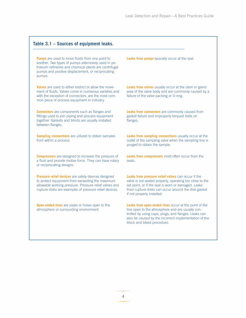
Table 3.1 – Sources of equipment leaks.
Pumps are used to move fluids from one point to
another. Two types of pumps extensively used in pe
troleum refineries and chemical plants are centrifugal
pumps and positive displacement, or reciprocating
pumps.
Valves are used to either restrict or allow the move
ment of fluids. Valves come in numerous varieties and
with the exception of connectors, are the most com
mon piece of process equipment in industry.
Connectors are components such as flanges and
fittings used to join piping and process equipment
together. Gaskets and blinds are usually installed
between flanges.
Sampling connections are utilized to obtain samples
from within a process.
Compressors are designed to increase the pressure of
a fluid and provide motive force. They can have rotary
or reciprocating designs.
Pressure relief devices are safety devices designed
to protect equipment from exceeding the maximum
allowable working pressure. Pressure relief valves and
rupture disks are examples of pressure relief devices.
Open-ended lines are pipes or hoses open to the
atmosphere or surrounding environment.
Leaks from pumps typically occur at the seal.
Leaks from valves usually occur at the stem or gland
area of the valve body and are commonly caused by a
failure of the valve packing or O-ring.
Leaks from connectors are commonly caused from
gasket failure and improperly torqued bolts on
fl anges.
Leaks from sampling connections usually occur at the
outlet of the sampling valve when the sampling line is
purged to obtain the sample.
Leaks from compressors most often occur from the
seals.
Leaks from pressure relief valves can occur if the
valve is not seated properly, operating too close to the
set point, or if the seal is worn or damaged. Leaks
from rupture disks can occur around the disk gasket
if not properly installed.
Leaks from open-ended lines occur at the point of the
line open to the atmosphere and are usually con
trolled by using caps, plugs, and flanges. Leaks can
also be caused by the incorrect implementation of the
block and bleed procedure.
4
Leak Detection and Repair—A Best Practices Guide
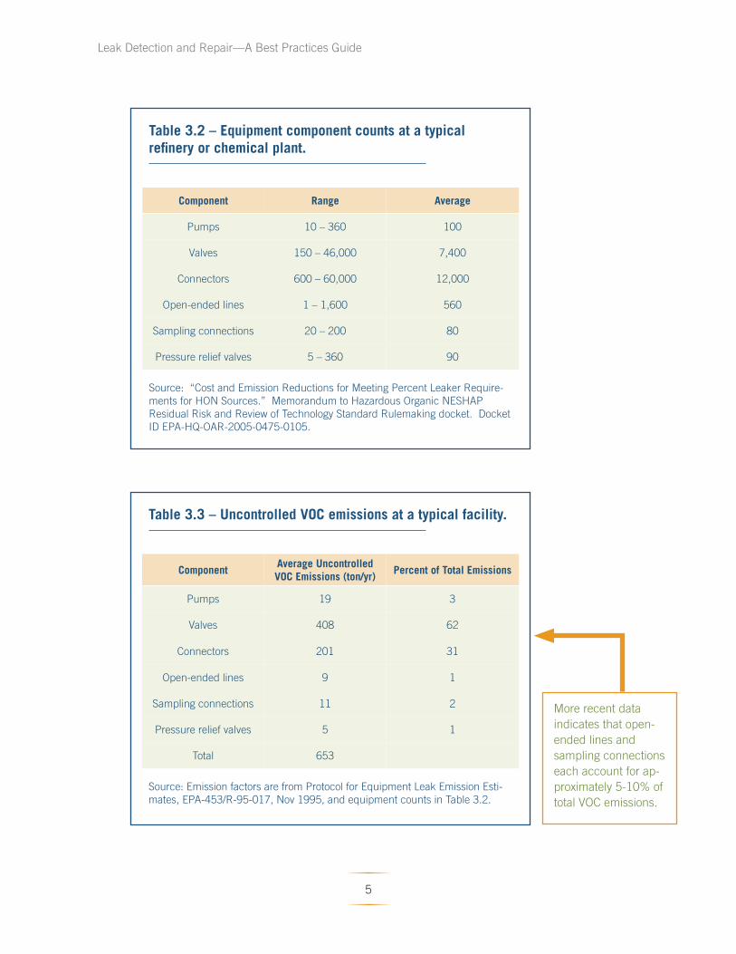
Table 3.2 – Equipment component counts at a typical refinery or chemical plant.
Component Range Average
Pumps 10 – 360 100
Valves 150 – 46,000 7,400
Connectors 600 – 60,000 12,000
Open-ended lines 1 – 1,600 560
Sampling connections 20 – 200 80
Pressure relief valves 5 – 360 90
Source: “Cost and Emission Reductions for Meeting Percent Leaker Require
ments for HON Sources.” Memorandum to Hazardous Organic NESHAP
Residual Risk and Review of Technology Standard Rulemaking docket. Docket
ID EPA-HQ-OAR-2005-0475-0105.
Table 3.3 – Uncontrolled VOC emissions at a typical facility.
Component Average Uncontrolled VOC Emissions (ton/yr)
Percent of Total Emissions
Pumps 19 3
Valves 408 62
Connectors 201 31
Open-ended lines 9 1
Sampling connections 11 2
Pressure relief valves 5 1
Total 653
Source: Emission factors are from Protocol for Equipment Leak Emission Esti
mates, EPA-453/R-95-017, Nov 1995, and equipment counts in Table 3.2.
More recent data
indicates that open-
ended lines and
sampling connections
each account for ap
proximately 5-10% of
total VOC emissions.
5
For a comprehensive discussion of equipment
leak regulation applicability determinations, see
Inspection Manual: Federal Equipment Leak
Regulations for the Chemical Manufacturing
Industry, Vol. 1: Inspection Manual, EPA/305/B-
98/011 (Dec 1998), Chapter 2.
Leak Detection and Repair—A Best Practices Guide
3.2 What regulations incorporate LDAR programs?
LDAR programs are required by many New Source
Performance Standards (NSPS), National Emission
Standards for Hazardous Air Pollutants (NESHAP),
State Implementation Plans (SIPs), the Resource
Conservation and Recovery Act (RCRA), and other
state or local requirements. There are 25 federal
standards that require facilities to implement
LDAR programs. Appendix A shows the 25 federal
standards that require the implementation of a for
mal LDAR program using Method 21. Appendix B
lists 28 other federal regulations that require some
Method 21 monitoring, but do not require LDAR
programs to be in place.
• NSPS (40 CFR Part 60) equipment leak
standards are related to fugitive emissions of
VOCs and apply to stationary sources that
commence construction, modifi cation, or
reconstruction after the date that an NSPS is
proposed in the Federal Register.
• NESHAP (40 CFR Parts 61, 63, and 65) equip
ment leak standards apply to both new and
existing stationary sources of fugitive VHAPs.
• RCRA (40 CFR Parts 264 and 265) equipment
leak standards apply to hazardous waste
treatment, storage, and disposal facilities.
• Many state and local air agencies incorporate
federal LDAR requirements by reference, but
some have established more stringent LDAR
requirements to meet local air quality needs.
A facility may have equipment that is subject to
multiple NSPS and NESHAP equipment leaks stan
dards. For example, a number of manufacturing
processes listed in the Hazardous Organic NES
HAP (HON) equipment leak standard (40 CFR 63,
Subpart H) may utilize equipment for which other
NESHAP or NSPS equipment leak standards could
apply (such as 40 CFR 60, Subpart VV). In addi
tion, one process line may be subject to one rule
and another process line subject to another rule.
Facilities must ensure that they are complying with
the proper equipment leak regulations if multiple
regulations apply.
6
Leak Detection and Repair—A Best Practices Guide
4.0 What Are the Benefits of an LDAR Program?
When the LDAR requirements were developed, EPA
estimated that petroleum refineries could reduce
emissions from equipment leaks by 63% by imple
menting a facility LDAR program. Additionally,
EPA estimated that chemical facilities could reduce
VOC emissions by 56% by implementing such a
program.
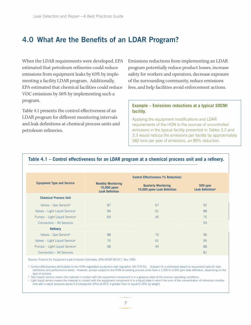
Table 4.1 presents the control effectiveness of an
LDAR program for different monitoring intervals
and leak definitions at chemical process units and
petroleum refi neries.
Emissions reductions from implementing an LDAR
program potentially reduce product losses, increase
safety for workers and operators, decrease exposure
of the surrounding community, reduce emissions
fees, and help facilities avoid enforcement actions.
Example – Emissions reductions at a typical SOCMI facility.
Applying the equipment modifications and LDAR
requirements of the HON to the sources of uncontrolled
emissions in the typical facility presented in Tables 3.2 and
3.3 would reduce the emissions per facility by approximately
582 tons per year of emissions, an 89% reduction.
Table 4.1 – Control effectiveness for an LDAR program at a chemical process unit and a refinery.
Equipment Type and Service
Control Effectiveness (% Reduction)
Monthly Monitoring 10,000 ppmv Leak Definition
Quarterly Monitoring 10,000 ppmv Leak Defi nition
500 ppm Leak Definitiona
Chemical Process Unit
Valves – Gas Serviceb 87 67 92
Valves – Light Liquid Servicec 84 61 88
Pumps – Light Liquid Servicec 69 45 75
Connectors – All Services 93
Refi nery
Valves – Gas Serviceb 88 70 96
Valves – Light Liquid Servicec 76 61 95
Pumps – Light Liquid Servicec 68 45 88
Connectors – All Services 81
Source: Protocol for Equipment Leak Emission Estimates, EPA-453/R-95-017, Nov 1995.
a Control effectiveness attributable to the HON-negotiated equipment leak regulation (40 CFR 63, Subpart H) is estimated based on equipment-specific leak
definitions and performance levels. However, pumps subject to the HON at existing process units have a 1,000 to 5,000 ppm leak definition, depending on the
type of process. b Gas (vapor) service means the material in contact with the equipment component is in a gaseous state at the process operating conditions. c Light liquid service means the material in contact with the equipment component is in a liquid state in which the sum of the concentration of individual constitu
ents with a vapor pressure above 0.3 kilopascals (kPa) at 20°C is greater than or equal to 20% by weight.
7

Leak Detection and Repair—A Best Practices Guide
4.1 Reducing Product Losses
In the petrochemical industry, saleable products
are lost whenever emissions escape from process
equipment. Lost product generally translates into
lost revenue.
4.2 Increasing Safety for Facility Workers and Operators
Many of the compounds emitted from refi neries
and chemical facilities may pose a hazard to ex
posed workers and operators. Reducing emissions
from leaking equipment has the direct benefi t of
reducing occupational exposure to hazardous com
pounds.
4.3 Decreasing Exposure for the Surrounding Community
In addition to workers and operators at a facil
ity, the population of a surrounding community
can be affected by severe, long-term exposure to
toxic air pollutants as a result of leaking equip
ment. Although most of the community exposure
may be episodic, chronic health effects can result
from long-term exposure to emissions from leaking
equipment that is either not identified as leaking or
not repaired.
4.4 Potentially Reducing Emission Fees
To fund permitting programs, some states and local
air pollution districts charge annual fees that are
based on total facility emissions. A facility with an
effective program for reducing leaking equipment
can potentially decrease the amount of these an
nual fees.
4.5 Avoiding Enforcement Actions
In setting Compliance and Enforcement National
Priorities for Air Toxics, EPA has identifi ed LDAR
programs as a national focus. Th erefore, facilities
can expect an increased number and frequency of
compliance inspections and a closer review of com
pliance reports submitted to permitting authorities
in an effort by the Agency to assess LDAR programs
and identify potential LDAR problems. A facil
ity with an effective LDAR program decreases the
chances of being targeted for enforcement actions
and avoids the costs and penalties associated with
rule violations.
Example – Cost of product lost.
In previous rulemaking efforts, EPA has esti
mated that the average value of product lost
due to equipment leaks is $1,370 per ton.a
Applying this cost factor results in a potential
savings of $730,000 per year per facility.
a Source: Hazardous Air Pollutant Emissions From
Process Units in the Synthetic Organic Chemical
Manufacturing Industry-Background Information
for Proposed Standards, Vol. 1C-Model Emission
Sources. Emission Standards Division, US EPA,
Office of Air and Radiation, OAQPS, Research
Triangle Park, NC. Nov 1992.
8
Leak Detection and Repair—A Best Practices Guide
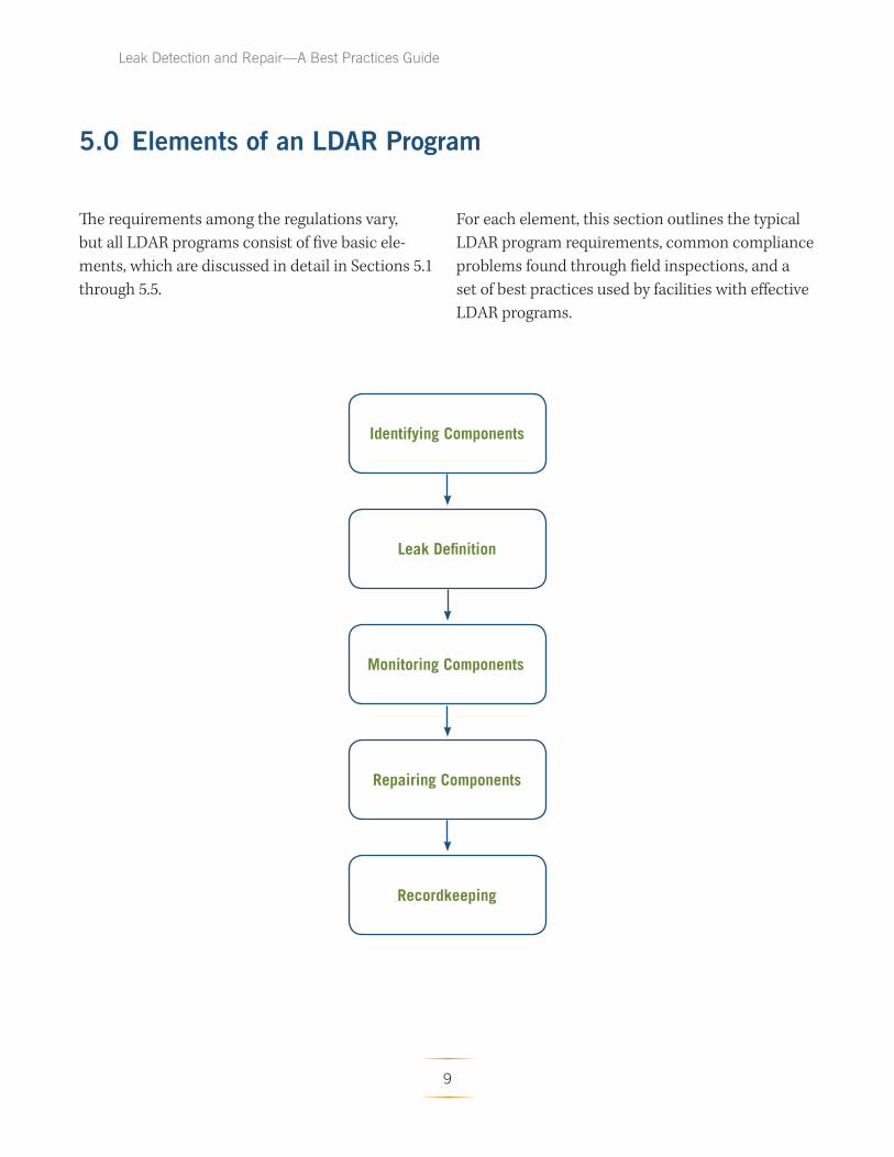
5.0 Elements of an LDAR Program
The requirements among the regulations vary, For each element, this section outlines the typical
but all LDAR programs consist of five basic ele- LDAR program requirements, common compliance
ments, which are discussed in detail in Sections 5.1 problems found through field inspections, and a
through 5.5. set of best practices used by facilities with eff ective
LDAR programs.
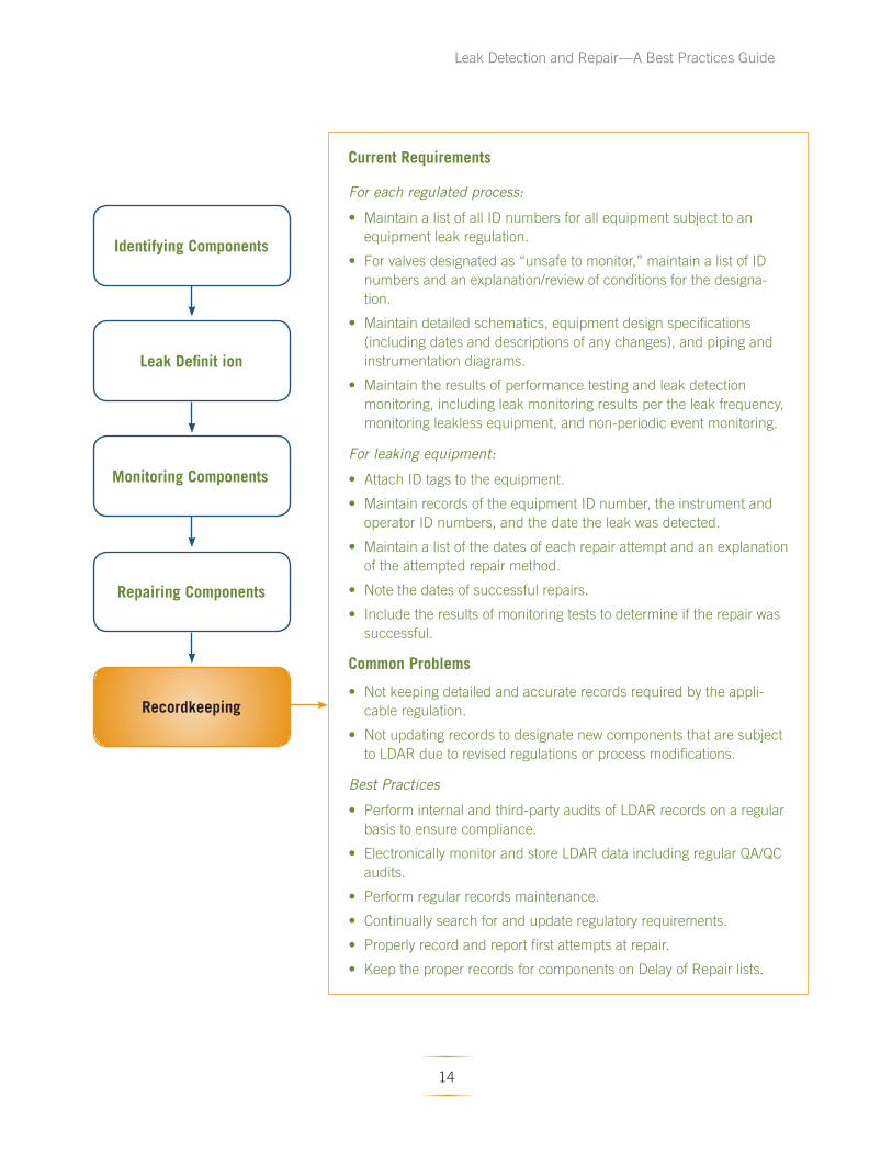
Identifying Components
Leak Definition
Monitoring Components
Repairing Components
Recordkeeping
9

Leak Detection and Repair—A Best Practices Guide
Current Requirements
• Assign a unique identification (ID) number to each regulated com
ponent.
• Record each regulated component and its unique ID number in a
log.
• Physically locate each regulated component in the facility, verify its
location on the piping and instrumentation diagrams (P&IDs) or pro
cess flow diagrams, and update the log if necessary. Some states
require a physical tag on each component subject to the LDAR
requirements.
Leak Definition • Identify each regulated component on a site plot plan or on a con
tinuously updated equipment log.
• Promptly note in the equipment log when new and replacement
pieces of equipment are added and equipment is taken out of ser
vice.
Monitoring Components Common Problems
• Not properly identifying all regulated equipment components.
• Not properly documenting exempt components (e.g., <300 hour
exemption and <5 (or <10) weight % HAP).
Repairing Components Best Practices
• Physically tag each regulated equipment component with a unique
ID number.
• Write the component ID number on piping and instrumentation
diagrams.
• Institute an electronic data management system for LDAR data and
records, possibly including the use of bar coding equipment.
• Periodically perform a field audit to ensure lists and diagrams ac
curately represent equipment installed in the plant.
Identifying Components
Recordkeeping
10
Leak Detection and Repair—A Best Practices Guide
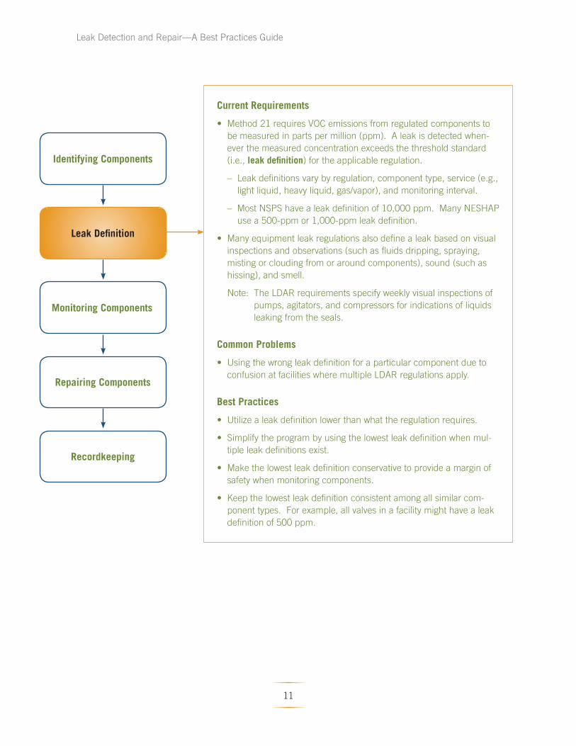
Current Requirements
• Method 21 requires VOC emissions from regulated components to
be measured in parts per million (ppm). A leak is detected when
ever the measured concentration exceeds the threshold standard
(i.e., leak definition) for the applicable regulation.
– Leak definitions vary by regulation, component type, service (e.g.,
light liquid, heavy liquid, gas/vapor), and monitoring interval.
– Most NSPS have a leak definition of 10,000 ppm. Many NESHAP
use a 500-ppm or 1,000-ppm leak definition.
Leak Definition • Many equipment leak regulations also define a leak based on visual
inspections and observations (such as fluids dripping, spraying,
misting or clouding from or around components), sound (such as
hissing), and smell.
Note: The LDAR requirements specify weekly visual inspections of
Monitoring Components pumps, agitators, and compressors for indications of liquids
leaking from the seals.
Identifying Components
Repairing Components
Common Problems
• Using the wrong leak definition for a particular component due to
confusion at facilities where multiple LDAR regulations apply.
Best Practices
• Utilize a leak definition lower than what the regulation requires.
• Simplify the program by using the lowest leak definition when mul
tiple leak definitions exist. Recordkeeping
• Make the lowest leak definition conservative to provide a margin of
safety when monitoring components.
• Keep the lowest leak definition consistent among all similar com
ponent types. For example, all valves in a facility might have a leak
definition of 500 ppm.
11

Leak Detection and Repair—A Best Practices Guide
Identifying Components
Leak Definition
Monitoring Components
Repairing Components
Recordkeeping
The monitoring interval is the frequency at
which individual com
ponent monitoring is conducted.
For example, valves are generally
required to be monitored once a
month using a leak detection in
strument, but the monitoring inter
val may be extended (e.g. to once
every quarter for each valve that
has not leaked for two successive
months for Part 60 Subpart VV,
or on a process unit basis of once
every quarter for process units
that have less than a 2% leak rate
for Part 63 Subpart H).
Current Requirements
• For many NSPS and NESHAP regulations with leak detection provisions,
the primary method for monitoring to detect leaking components is EPA
Reference Method 21 (40 CFR Part 60, Appendix A).
• Method 21 is a procedure used to detect VOC leaks from process equip
ment using a portable detecting instrument.
• Appendix C of this guide explains the general procedure and Appendix D
presents the complete Method 21 requirements.
• Monitoring intervals vary according to the applicable regulation, but are typ
ically weekly, monthly, quarterly, and yearly. For connectors, the monitoring
interval can be every 2, 4, or 8 years. The monitoring interval depends on
the component type and periodic leak rate for the component type.
Common Problems
• Not following Method 21 properly.
• Failing to monitor at the maximum leak location (once the highest read
ing is obtained by placing the probe on and around the interface, hold the
probe at that location approximately two times the response rate of the
instrument).
• Not monitoring long enough to identify a leak.
• Holding the detection probe too far away from the component interface.
The reading must be taken at the interface.
• Not monitoring all potential leak interfaces.
• Using an incorrect or an expired calibration gas.
• Not monitoring all regulated components.
• Not completing monitoring if the first monitoring attempt is unsuccessful
due to equipment being temporarily out of service.
Best Practices
• Although not required by Method 21, use an automatic (electronic) data
logger to save time, improve accuracy, and provide an audit record.
• Audit the LDAR program to help ensure that the correct equipment is being
monitored, Method 21 procedures are being followed properly, and the
required records are being kept.
• Monitor components more frequently than required by the regulations.
• Perform QA/QC of LDAR data to ensure accuracy, completeness, and to
check for inconsistencies.
• Eliminate any obstructions (e.g., grease on the component interface) that
would prevent monitoring at the interface.
• If a rule allows the use of alternatives to Method 21 monitoring, Method
21 should still be used periodically to check the results of the alternative
monitoring method.
12
Leak Detection and Repair—A Best Practices Guide
Identifying Components
Leak Definition
Monitoring Components
Repairing Components
Recordkeeping
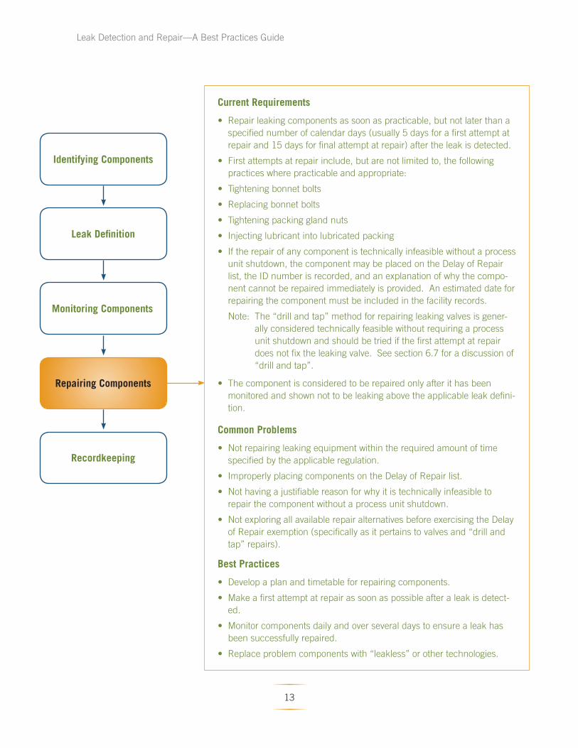
Current Requirements
• Repair leaking components as soon as practicable, but not later than a
specified number of calendar days (usually 5 days for a first attempt at
repair and 15 days for final attempt at repair) after the leak is detected.
• First attempts at repair include, but are not limited to, the following
practices where practicable and appropriate:
• Tightening bonnet bolts
• Replacing bonnet bolts
• Tightening packing gland nuts
• Injecting lubricant into lubricated packing
• If the repair of any component is technically infeasible without a process
unit shutdown, the component may be placed on the Delay of Repair
list, the ID number is recorded, and an explanation of why the compo
nent cannot be repaired immediately is provided. An estimated date for
repairing the component must be included in the facility records.
Note: The “drill and tap” method for repairing leaking valves is gener
ally considered technically feasible without requiring a process
unit shutdown and should be tried if the first attempt at repair
does not fix the leaking valve. See section 6.7 for a discussion of
“drill and tap”.
• The component is considered to be repaired only after it has been
monitored and shown not to be leaking above the applicable leak defini
tion.
Common Problems
• Not repairing leaking equipment within the required amount of time
specified by the applicable regulation.
• Improperly placing components on the Delay of Repair list.
• Not having a justifiable reason for why it is technically infeasible to
repair the component without a process unit shutdown.
• Not exploring all available repair alternatives before exercising the Delay
of Repair exemption (specifically as it pertains to valves and “drill and
tap” repairs).
Best Practices
• Develop a plan and timetable for repairing components.
• Make a first attempt at repair as soon as possible after a leak is detect
ed.
• Monitor components daily and over several days to ensure a leak has
been successfully repaired.
• Replace problem components with “leakless” or other technologies.
13
Leak Detection and Repair—A Best Practices Guide
Identifying Components
Leak Definit ion
Monitoring Components
Repairing Components
Recordkeeping
Current Requirements
For each regulated process:
• Maintain a list of all ID numbers for all equipment subject to an
equipment leak regulation.
• For valves designated as “unsafe to monitor,” maintain a list of ID
numbers and an explanation/review of conditions for the designa
tion.
• Maintain detailed schematics, equipment design specifications
(including dates and descriptions of any changes), and piping and
instrumentation diagrams.
• Maintain the results of performance testing and leak detection
monitoring, including leak monitoring results per the leak frequency,
monitoring leakless equipment, and non-periodic event monitoring.
For leaking equipment:
• Attach ID tags to the equipment.
• Maintain records of the equipment ID number, the instrument and
operator ID numbers, and the date the leak was detected.
• Maintain a list of the dates of each repair attempt and an explanation
of the attempted repair method.
• Note the dates of successful repairs.
• Include the results of monitoring tests to determine if the repair was
successful.
Common Problems
• Not keeping detailed and accurate records required by the appli
cable regulation.
• Not updating records to designate new components that are subject
to LDAR due to revised regulations or process modifications.
Best Practices
• Perform internal and third-party audits of LDAR records on a regular
basis to ensure compliance.
• Electronically monitor and store LDAR data including regular QA/QC
audits.
• Perform regular records maintenance.
• Continually search for and update regulatory requirements.
• Properly record and report first attempts at repair.
• Keep the proper records for components on Delay of Repair lists.
14
Leak Detection and Repair—A Best Practices Guide
6.0 What Compliance Problems Have Been Found With Current LDAR Programs?
Many regulatory agencies determine the compli
ance status of LDAR programs based on a review of
submitted paperwork. Some conduct walk-through
inspections to review LDAR records maintained
on site and perform a visual check of monitoring
practices. However, a records review will not show
if monitoring procedures are being followed. Simi
larly, the typical walkthrough inspection will not
likely detect improper monitoring practices since
operators will tend to ensure that they are following
proper procedures when they are being watched.
EPA’s National Enforcement Investigations Center
(NEIC) conducted a number of sampling investiga
tions of LDAR programs at 17 petroleum refi neries.
Appendix E summarizes the comparative monitor
ing results, and Appendix F contains a copy of the
1999 Enforcement Alert that explains the monitor
ing results. The investigations consisted of records
review and comparative leak monitoring (compar
ing the leak rate found by NEIC to the facility’s
historic leak rate) at a subset of the facility’s total
components. These investigations have shown
a pattern of significantly higher equipment leak
rates (5%) than what the refineries reported (1.3%).
While there have been improvements since 1999,
facility audits are still showing signifi cantly elevat
ed leak rates, especially in the chemical manufac
turing industries.
The discrepancy in leak rates indicates that moni
toring staff may not be complying with Method 21
procedures. Failure to accurately detect leaks may
be due to a lack of internal quality control oversight
or management accountability for the LDAR pro
grams regardless of whether the monitoring is done
by contractors or in-house personnel.
Each leak that is not detected and repaired is a lost
opportunity to reduce emissions. In the October
1999 Enforcement Alert, EPA estimates that an ad
ditional 40,000 tons of VOCs are emitted annually
from petroleum refineries because leaking valves
are not found and repaired.
Several important factors contribute to failing to
identify and repair leaking components:
1. Not identifying all regulated compo
nents/units in inventory
If a facility does not properly identify all of its
regulated components, some leaks may go
unidentified. Unidentified components may
leak or have existing leaks that will worsen
over time if the components are not properly
identified, monitored and repaired. Facili
ties can fail to identify regulated components
when new processes are constructed, exist
ing process are modified, or new or revised
equipment leak regulations are published.
2. Not monitoring components
In some cases, the number of components re
ported to have been monitored may indicate
problems with monitoring procedures. What
facility inspectors have found:
• A data logger time stamp showed valves
being monitored at the rate of one per
second with two valves occasionally be
15

Leak Detection and Repair—A Best Practices Guide
ing monitored within the same 1-second
period.
• At one facility, a person reported monitor
ing 8,000 components in one day (assum
ing an 8-hour work day, that represents
one component every 3.6 seconds).
• Records evaluations showed widely vary
ing component monitoring counts, sug
gesting equipment might not always be
monitored when required.
• Equipment was marked “temporarily out
of service” because the initial inspection
attempt could not be performed. Howev
er, the equipment was in service for most
of the period, and no subsequent (or prior)
inspection attempts were performed to
meet the monitoring requirement.
However, even when records show a realistic
number of components are being monitored,
if there are no oversight or accountability
checks, then there is no guarantee that com
ponents are actually being monitored.
A well-trained LDAR inspection
team (two people) can monitor
approximately 500-700 valves
per day.
3. Insufficient time to identify a leak
In other cases, facilities are not following
proper monitoring procedures, resulting in a
lower number of leaking components being
reported.
• If a worker moves the probe around the
component interface so rapidly that the
instrument does not have time to properly
respond, then a component may never be
identified as leaking.
• If a worker fails to find the maximum leak
location for the component and then does
not spend twice the response time at that
location, then the monitoring instrument
will not measure the correct concentra
tion of hydrocarbons and the leak may
go undetected. Optical leak imaging
shows the importance of identify
ing the maximum leak location, as
hydrocarbons are quickly dispersed
and diluted by air currents around the
component.
4. Holding the probe away from the compo
nent interface
The probe must be placed at the proper
interface of the component being analyzed.
Placing the probe even 1 centimeter from the
interface can result in a false reading, indicat
ing that the component is not leaking, when
in fact it is leaking. Eliminate any issues (e.g.,
grease on the component interface) that pre
vent monitoring at the interface (e.g., remove
excess grease from the component before
monitoring or use a monitor that won’t be
impacted by the grease and is easy to clean.
16

A California Bay Area Air Quality
Management District rule effectiveness
study showed that if an operator
measured 1 centimeter (0.4 inches)
from the component leak interface, the
operator would find only 79% of valves
leaking between 100 ppm and 500
ppm and only 43% of the valves leaking
above 500 ppm.
Source: Draft Staff Report, Regulation 8,
Rule 18, Equipment Leaks, Bay Area Air
Quality Management District, Jul 1997.
Leak Detection and Repair—A Best Practices Guide
For equipment with rotating shafts (pumps
and compressors), Method 21 requires the
probe be placed within 1 centimeter of the
Typical TVA (Toxic Vapor
Analyzer) response times are
around 2 – 4 seconds.
shaft-seal interface. Placing the probe at the
surface of the rotating shaft is a safety hazard
and should be avoided.
5. Failing to properly maintain monitoring
instrument
Factors that may prevent the instrument
from identifying leaks are:
• Not using an instrument that meets the
specifications required in Method 21, sec
tion 6.
• Dirty instrument probes;
• Leakage from the instrument probes;
• Not zeroing instrument meter;
• Incorrect calibration gases used; and
• Not calibrating the detection instrument
on a daily basis.
6. Improperly identifying components as
“unsafe” or “diffi cult” to monitor
Components that are identified as being
“unsafe to monitor” or “diffi cult to monitor”
must be identified as such because there is a
safety concern or an accessibility issue that
prevents the component from being success
fully monitored.
All unsafe or diffi cult-to-monitor compo
nents must be included on a log with identi
fication numbers and an explanation of why
the component is “unsafe to monitor” or “dif
ficult to monitor.” Monitoring can be deferred
for all such components, but the facility must
maintain a plan that explains the conditions
under which the components become safe to
monitor or no longer difficult to monitor.
17
Leak Detection and Repair—A Best Practices Guide
7. Improperly placing components/units
on the “Delay of Repair” list
Generally, placing a leaking component on
the “Delay of Repair” list is permissible only
when the component is technically infeasible
to repair without a process unit shutdown
(e.g., for valves the owner/operator must
demonstrate that the emissions from imme
diate repair will be greater than waiting for
unit shutdown).
Repair methods may exist, such as “drill and
tap” for valves, that allow leaks to be fi xed
while the component is still in service. Fail
ing to consider such repair methods before
exercising the “Delay of Repair” list may con
stitute noncompliance with repair require
ments (usually 15 days under federal LDAR
standards).
Components placed on the “Delay of Repair”
list must be accompanied by their ID num
bers and an explanation of why they have
been placed on the list. Th ese components
cannot remain on the list indefinitely – they
must be repaired by the end of the next pro
cess unit shutdown.
Drill and Tap is a repair method where
a hole is drilled into the valve pack
ing gland and tapped, so that a small
valve and fitting can be attached to the gland.
A packing gun is connected to this fitting and
the small valve is opened allowing new packing
material to be pumped into the packing gland.
Many companies consider this a permanent
repair technique, as newer, pumpable packing
types are frequently superior to the older pack
ing types they replace. Packing types can be
changed and optimized for the specific applica
tion over time.
18
Leak Detection and Repair—A Best Practices Guide
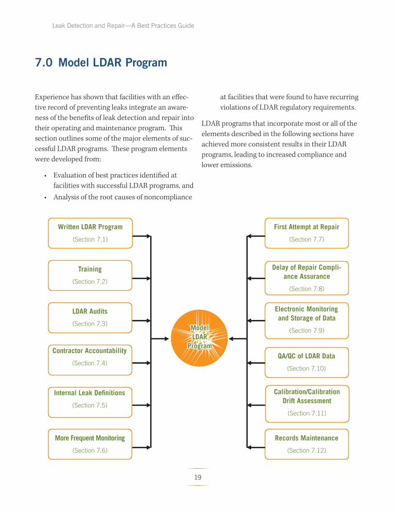
7.0 Model LDAR Program
Experience has shown that facilities with an eff ec
tive record of preventing leaks integrate an aware
ness of the benefits of leak detection and repair into
their operating and maintenance program. Th is
section outlines some of the major elements of suc
cessful LDAR programs. These program elements
were developed from:
• Evaluation of best practices identifi ed at
facilities with successful LDAR programs, and
• Analysis of the root causes of noncompliance
at facilities that were found to have recurring
violations of LDAR regulatory requirements.
LDAR programs that incorporate most or all of the
elements described in the following sections have
achieved more consistent results in their LDAR
programs, leading to increased compliance and
lower emissions.
Written LDAR Program
(Section 7.1)
Training
(Section 7.2)
QA/QC of LDAR Data
(Section 7.10)
Calibration/Calibration Drift Assessment
(Section 7.11)
Electronic Monitoring and Storage of Data
(Section 7.9)
First Attempt at Repair
(Section 7.7)
More Frequent Monitoring
(Section 7.6)
LDAR Audits
(Section 7.3)
Contractor Accountability
(Section 7.4)
Internal Leak Definitions
(Section 7.5)
Records Maintenance
(Section 7.12)
Delay of Repair Compliance Assurance
(Section 7.8)
ModelModel LDARLDAR
ProgramProgram
19

Leak Detection and Repair—A Best Practices Guide
7.1 Written LDAR Program
A written LDAR program specifies the regulatory
requirements and facility-specific procedures for re
cordkeeping certifications, monitoring, and repairs.
A written program also delineates the roles of each
person on the LDAR team as well as documents all
the required procedures to be completed and data
to be gathered, thus establishing accountability.
The plan should identify all process units subject
to federal, state, and local LDAR regulations and
be updated as necessary to ensure accuracy and
continuing compliance.
Elements:
• An overall, facility-wide leak rate goal that will be a
target on a process-unit-by-process-unit basis;
• A list of all equipment in light liquid and/or in gas/
vapor service that has the potential to leak VOCs
and VHAPs, within process units that are owned
and maintained by each facility;
• Procedures for identifying leaking equipment
within process units;
• Procedures for repairing and keeping track of leak
ing equipment;
• A process for evaluating new and replacement
equipment to promote the consideration of install
ing equipment that will minimize leaks or eliminate
chronic leakers;
• A list of “LDAR Personnel” and a description
of their roles and responsibilities, including the
person or position for each facility that has the
authority to implement improvements to the LDAR
program; and
• Procedures (e.g., a Management of Change pro
gram) to ensure that components added to each
facility during maintenance and construction are
evaluated to determine if they are subject to LDAR
requirements, and that affected components are
integrated into the LDAR program.
Within thirty (30) days after developing the writ
ten facility-wide LDAR program, submit a copy of
the Program to EPA and to the appropriate state
agency.
7.2 Training
A training program will provide LDAR personnel
the technical understanding to make the written
LDAR program work. It also will educate members
of the LDAR team on their individual responsibili
ties. These training programs can vary according to
the level of involvement and degree of responsibility
of LDAR personnel.
Elements:
• Provide and require initial training and annual
LDAR refresher training for all facility employees
assigned LDAR compliance responsibilities, such
as monitoring technicians, database users, QA/QC
personnel, and the LDAR Coordinator;
• For other operations and maintenance personnel
with responsibilities related to LDAR, provide and
require an initial training program that includes
instruction on aspects of LDAR that are relevant to
their duties (e.g., operators and mechanics per
forming valve packing and unit supervisors that
approve delay of repair work). Provide and require
“refresher” training in LDAR for these personnel at
least every three years.
• Collect training information and records of contrac
tors, if used.
20

Leak Detection and Repair—A Best Practices Guide
7.3 LDAR Audits
Whether LDAR monitoring is done in house or
contracted to third parties outside the company,
the potential exists for LDAR staff not to adhere
correctly to the LDAR program. Internal and
third-party audits of a facility LDAR program are
a critical component of effective LDAR programs.
The audits check that the correct equipment is
being monitored, Method 21 procedures are being
followed, leaks are being fixed, and the required
records are being kept. In short, the audits ensure
that the LDAR program is being conducted cor
rectly and problems are identified and corrected.
Elements:
• Review records on a regular cycle to ensure that all
required LDAR-related records, logs, and databases
are being maintained and are up to date.
• Ensure and document that the correct equipment is
included in the LDAR program and that equipment
identified as leaking is physically tagged with the
equipment ID number.
• Observe the calibration and monitoring techniques
used by LDAR technicians, in particular to ensure
the entire interface is checked and the probe is held
at the interface, not away from the interface.
• Retain a contractor to perform a third-party audit of
the facility LDAR program at least once every four
(4) years.
• Perform facility-led audits every four (4) years.
– Use personnel familiar with the LDAR program
and its requirements from one or more of the
company’s other facilities or locations (if available).
– Perform the first round of facility-led LDAR audits
no later than two (2) years after completion of the
third-party audits outlined above, and every four
(4) years thereafter.
– This rotation ensures that the facility is being
audited once every two (2) years.
• If areas of noncompliance are discovered, initiate a
plan to resolve and document those issues.
• Implement, as soon as practicable, steps necessary
to correct causes of noncompliance, and prevent, to
the extent practicable, a recurrence of the cause of
the noncompliance.
• Retain the audit reports and maintain a written
record of the corrective actions taken in response to
any deficiencies identified.
21
7.4 Contractor Accountability
Contractors performing monitoring are frequently
compensated for the number of components they
monitor, which might provide an incentive to rush
through monitoring procedures and not adhere to
Method 21 requirements for response time, moni
toring distance, etc. If this happens, some equip
ment leaks may not be detected. To overcome this
potential problem, facilities should have in place
sufficient oversight procedures to increase the ac
countability of contractors.
Elements:
• Write contracts that emphasize the quality of
work instead of the quantity of work only.
• Require contractors to submit documentation
that their LDAR personnel have been trained on
Method 21 and facility-specific LDAR proce
dures.
• Ensure that the contractor has a procedure in
place to review and certify the monitoring data
before submitting the data to the facility.
• Review daily results of contractor work to en
sure that a realistic number of components are
being monitored.
• Perform spot audits in the field to ensure that
Method 21 procedures are being followed.
This can include spot-checking monitored
components with another hydrocarbon analyzer
or following LDAR personnel as they perform
monitoring.
• Have periodic reviews of contractor perfor
mance (e.g., quarterly or semi-annually) to
resolve issues and correct problems.
Leak Detection and Repair—A Best Practices Guide
7.5 Internal Leak Definition for Valves and Pumps
The varying leak definitions that can apply to
different process units and components can be
confusing and lead to errors in properly identifying
leaks. To counter this potential problem, operate
your LDAR program using an internal leak defi ni
tion for valves and pumps in light liquid or gas
vapor service. The internal leak definition would be
equivalent to or lower than the applicable defi ni
tions in your permit and the applicable federal,
state, and local regulations. Monitoring against a
uniform definition that is lower than the applicable
regulatory definition will reduce errors and provide
a margin of safety for identifying leaking compo
nents. The internal leak definition would apply to
valves and pumps (and possibly connectors) in light
liquid or gas vapor service.
Elements:
• Adopt a 500-ppm or lower internal leak definition
for VOCs for all valves in light liquid and/or gas
vapor service, excluding pressure relief devices.
• Adopt a 2,000-ppm or lower internal leak definition
for pumps in light liquid and/or gas/vapor service.
• Record, track, repair, and monitor leaks in excess
of the internal leak definition. Repair and monitor
leaks that are greater than the internal leak defini
tions but less than the applicable regulatory leak
definitions within thirty (30) days of detection.
Consent Decrees between EPA and many chemical
facilities subject to the HON require using a 250-ppm
leak definition for valves and connectors and a 500
ppm leak definition for pumps.
Note: If a state or local agency has lower leak defini
tions, then the internal leak definition should
be set to the lowest definition or even lower to
include/allow for margin of error.
22
Leak Detection and Repair—A Best Practices Guide
7.6 More Frequent Monitoring
Many regulations allow for less frequent monitor
ing (i.e. skip periods) when good performance (as
defined in the applicable regulation) is demon
strated. Skip period is an alternative work practice
found in some equipment leak regulations and
usually applies only to valves and connectors. After
a specified number of leak detection periods (e.g.,
monthly) during which the percentage of leaking
components is below a certain value (e.g., 2% for
NSPS facilities), a facility can monitor less fre
quently (e.g., quarterly) as long as the percentage
of leaking components remains low. Th e facility
must keep a record of the percentage of the compo
nent type found leaking during each leak detection
period.
Experience has shown that poor monitoring rather
than good performance has allowed facilities to
take advantage of the less frequent monitoring
provisions. To ensure that leaks are still being
identified in a timely manner and that previously
unidentified leaks are not worsening over time,
implement a plan for more frequent monitoring for
components that contribute most to equipment
leak emissions.
Elements:
• Monitor pumps in light liquid and/or gas vapor
service on a monthly basis.
• Monitor valves in light liquid and/or gas vapor
service – other than difficult-to-monitor or unsafe-
to-monitor valves – with no skip periods.
Consent Decrees between EPA and many chemi
cal facilities subject to the HON require semiannual
monitoring of connectors.
7.7 Repairing Leaking Components
To stop detected leaks while they are still small,
most rules require a first attempt at repair within 5
days of the leak detection and a final repair within
15 days. However, any component that cannot be
repaired within those time frames must be placed
on a “Delay of Repair” list to be repaired during the
next shutdown cycle.
First attempts at repair include, but are not limited
to, the following best practices where practicable
and appropriate:
• Tightening bonnet bolts;
• Replacing bonnet bolts;
• Tightening packing gland nuts; and
• Injecting lubricant into lubricated packing.
Elements:
• Schedule the “first attempt at repair” of those
components that the monitoring personnel are not
authorized to repair consistent with the existing
regulatory requirements.
• Monitor the component for which a “first attempt
at repair” was performed no later than the next
regular business day to ensure the leak has not
worsened.
• If the first attempt at repair has not succeeded then
other methods, such as “drill and tap” should be
employed where feasible. Drill and tap procedures
are no longer considered extraordinary practices.
23
7.8 Delay of Repair Compliance Assurance
Any component that cannot be repaired during the
specified repair interval must be placed on a “Delay
of Repair” list to be repaired during the next shut
down cycle. Delay of repair compliance assurance
procedures ensure that the appropriate equipment
is justifiably on the “Delay of Repair” list and that
facilities have a plan to fix these components.
Elements:
• Have the unit supervisor approve in advance
and certify all components that are technically
infeasible to repair without a process unit shut
down.
• Continue to monitor equipment that is placed on
the “Delay of Repair” list in the facility’s regular
LDAR monitoring. For leaks above the internal
leak definition rate and below the regulatory
rate, put the equipment on the “Delay of Repair”
list within 30 days.
• Implement the following repair policies and
procedures within 15 days of implementing the
written LDAR program:
– For valves, other than control valves or pres
sure relief valves, that are leaking at a rate of
10,000 ppm or greater and cannot be feasibly
repaired without a process unit shutdown,
use “drill and tap” repair methods to fix the
leaking valve, unless you can determine and
document that there is a safety, mechanical,
or major environmental concern posed by
repairing the leak in this manner.
– Perform up to two “drill and tap” repair at
tempts to repair a leaking valve, if necessary,
within 30 days of identifying the leak.
Leak Detection and Repair—A Best Practices Guide
7.9 Electronic Monitoring and Storage of LDAR Data
Electronic monitoring and storage of LDAR data
will help evaluate the performance of monitor
ing personnel (via time/date stamps), improve
accuracy, provide an effective means for QA/QC,
and retrieve records in a timely manner for review
purposes. Incorporate and maintain an electronic
database for storing and reporting LDAR data. Use
data loggers or other data collection devices during
all LDAR monitoring.
Elements:
• Use best efforts to transfer, on a daily basis, elec
tronic data from electronic data logging devices to
the database.
• For all monitoring events in which an electronic
data collection device is used, include a time and
date stamp, operator identification, and instrument
identifi cation.
• Paper logs can be used where necessary or more
feasible (e.g., small rounds, re-monitoring fixed
leaks, or when data loggers are not available
or broken), and should record, at a minimum,
the monitoring technician, date, and monitoring
equipment used.
• Transfer any manually recorded monitoring data to
the database within 7 days of monitoring.
• Review records to identify “problem” components
for preventative maintenance (repair prior to an
ticipated failure) or for replacement with “leakless”
technology.
24
Leak Detection and Repair—A Best Practices Guide
7.10 QA/QC of LDAR Data
QA/QC audits ensure that Method 21 procedures
are being followed and LDAR personnel are moni
toring the correct components in the proper man
ner. Develop and implement a procedure to ensure
QA/QC review of all data generated by LDAR
monitoring technicians on a daily basis or at the
conclusion of each monitoring episode.
Elements:
Some QA/QC procedures include:
• Daily review/sign-off by monitoring technicians
of the data they collected to ensure accuracy
and validity.
• Periodic review of the daily monitoring reports
generated in conjunction with recordkeeping
and reporting requirements.
• Quarterly QA/QC of the facility’s and contractor’s
monitoring data including:
– Number of components monitored per tech
nician;
– Time between monitoring events; and
– Abnormal data patterns.
7.11 Calibration/Calibration Drift Assessment
Always calibrate LDAR monitoring equipment us
ing an appropriate calibration gas, in accordance
with 40 CFR Part 60, EPA Reference Test Method
21.
Elements:
• Conduct calibration drift assessments of LDAR
monitoring equipment at the end of each moni
toring shift, at a minimum.
• Conduct the calibration drift assessment using, at
a minimum, approximately 500 ppm of calibra
tion gas.
• If any calibration drift assessment after the initial
calibration shows a negative drift of more than
10% from the previous calibration, re-monitor all
valves that were monitored since the last cali
bration with a reading of greater than 100 ppm.
Re-monitor all pumps that were monitored since
the last calibration with a reading of greater than
500 ppm.
25

Leak Detection and Repair—A Best Practices Guide
7.12 Records Maintenance
Organized and readily available records are one
potential indication of an effective LDAR program.
Well-kept records may also indicate that the LDAR
program is integrated into the facility’s routine
operation and management. The equipment leak
regulations specify recordkeeping and reporting
requirements; incorporating the elements below
will help ensure your facility LDAR records are
thorough and complete.
Elements: (4) The number of valves and pumps found
leaking;Records to maintain:
(5) The number of “difficult to monitor” pieces • A certification that the facility implemented the
of equipment monitored;“first attempt at repair” program.
(6) A list of all equipment currently on the• A certification that the facility implemented
“Delay of Repair” list and the date eachQA/QC procedures for review of data generated
component was placed on the list;by LDAR technicians.
(7) The number of repair attempts not com• An identification of the person/position at each
pleted promptly or completed within 5facility responsible for LDAR program perfor
days;mance as defined in the written program.
(8) The number of repairs not completed• A certification that the facility developed and
within 30 days and the number of compo-implemented a tracking program for new
nents not placed on the “Delay of Repair”valves and pumps added during maintenance
list; andand construction defined in the written pro
(9) The number of chronic leakers that do notgram.get repaired.
• A certification that the facility properly com
pleted calibration drift assessments. • Records of audits and corrective actions. Prior
to the first third-party audit at each facility, • A certification that the facility implemented the
include in your records a copy of each audit“delay of repair” procedures.
report from audits conducted in the previous • The following information on LDAR monitoring: calendar year and a summary of the actions
(1) The number of valves and pumps present planned or taken to correct all deficiencies
in each process unit during the quarter; identified in the audits.
(2) The number of valves and pumps moni- • For the audits performed in prior years, iden
tored in each process unit; tification of the auditors and documentation
(3) An explanation for missed monitoring if that a written plan exists identifying corrective
the number of valves and pumps present action for any deficiencies identified and that
exceeds the number of valves and pumps this plan is being implemented.
monitored during the quarter;
26
Leak Detection and Repair—A Best Practices Guide
8.0 Sources of Additional Information
Inspection Manual: Federal Equipment Leak Regulations for the Chemical Manufacturing Industry,
EPA/305/B-98/011, December 1998.
http://cfpub.epa.gov/compliance/resources/publications/assistance/sectors/chemical/index.cfm
Vol 1: Inspection Manual
http://www.epa.gov/compliance/resources/publications/assistance/sectors/insmanvol1.pdf
Vol 2: Chemical Manufacturing Industry Regulations (3 parts on the Internet)
http://www.epa.gov/compliance/resources/publications/assistance/sectors/insmanvol2pt1.pdf
http://www.epa.gov/compliance/resources/publications/assistance/sectors/insmanvol2pt2.pdf
http://www.epa.gov/compliance/resources/publications/assistance/sectors/insmanvol2pt3.pdf
Vol 3: Petroleum Refining Industry Regulations
http://www.epa.gov/compliance/resources/publications/assistance/sectors/insmanvol3.pdf
1995 Protocol for Equipment Leak Emission Estimates, EPA-453/R-95-017, Nov 1995.
http://www.epa.gov/ttnchie1/efdocs/equiplks.pdf
Enforcement Alert, EPA Office of Enforcement and Compliance Assurance,
EPA 300-N-99-014, Oct 1999.
http://www.epa.gov/compliance/resources/newsletters/civil/enfalert/emissions.pdf
National Petroleum Refinery Initiative, EPA.
http://www.epa.gov/compliance/resources/cases/civil/caa/refi neryinitiative032106.pdf
Petroleum Refinery Initiative Fact Sheet, EPA.
http://www.epa.gov/compliance/resources/cases/civil/caa/petroleumrefi nery-fcsht.html
Petroleum Refinery National Priority Case Results.
http://www.epa.gov/compliance/resources/cases/civil/caa/oil/
Draft Staff Report, Regulation 8, Rule 18, Equipment Leaks, Bay Area Air Quality Management District,
Jul 1997.
http://www.baaqmd.gov/pln/ruledev/8-18/1997/0818_sr_071097.pdf
Standards of Performance for Equipment Leaks of VOC in the Synthetic Organic Chemicals Manu
facturing Industry; Standards of Performance for Equipment Leaks of VOC in Petroleum Refi neries;
Proposed Rule, [EPA-HQ-OAR-2006-0699; FRL- ] RIN 2060-AN71.
http://www.epa.gov/ttn/oarpg/t3/fr_notices/equip_leak_prop103106.pdf
Industrial Organic Chemicals Compliance Incentive Program, EPA Compliance and Enforcement.
http://www.epa.gov/compliance/incentives/programs/ioccip.html
27

Leak Detection and Repair—A Best Practices Guide
Leak Detection and Repair Program Developments.
http://www.epa.gov/compliance/neic/fi eld/leak.html
Compliance and Enforcement Annual Results: Important Environmental Problems / National Priorities.
http://www.epa.gov/compliance/resources/reports/endofyear/eoy2006/sp-airtoxics-natl-priorities.html
Portable Instruments User’s Manual For Monitoring VOC Sources, EPA-340/1-86-015.
Inspection Techniques For Fugitive VOC Emission Sources, EPA 340/1-90-026a,d,e,f (rev May 1993) Course #380.
Environmental compliance assistance resources can be found at:
http://cfpub.epa.gov/clearinghouse/
http://www.assistancecenters.net/
http://www.epa.gov/compliance/assistance/sectors/index.html
28

Leak Detection and Repair—A Best Practices Guide
Appendix A Federal Regulations That Require a Formal LDAR Program With Method 21
Part
40 CFR
Subpart Regulation Title
60 VV SOCMI VOC Equipment Leaks NSPS
60 DDD Volatile Organic Compound (VOC) Emissions from the Polymer Manufacturing
Industry
60 GGG Petroleum Refinery VOC Equipment Leaks NSPS
60 KKK Onshore Natural Gas Processing Plant VOC Equipment Leaks NSPS
61 J National Emission Standard for Equipment Leaks (Fugitive Emission Sources) of
Benzene
61 V Equipment Leaks NESHAP
63 H Organic HAP Equipment Leak NESHAP (HON)
63 I Organic HAP Equipment Leak NESHAP for Certain Processes
63 J Polyvinyl Chloride and Copolymers Production NESHAP
63 R Gasoline Distribution Facilities (Bulk Gasoline Terminals and Pipeline Breakout
Stations)
63 CC Hazardous Air Pollutants from Petroleum Refi neries
63 DD Hazardous Air Pollutants from Off-Site Waste and Recovery Operations
63 SS Closed Vent Systems, Control Devices, Recovery Devices and Routing to a Fuel
Gas System or a Process
63 TT Equipment Leaks – Control Level 1
63 UU Equipment Leaks – Control Level 2
63 YY Hazardous Air Pollutants for Source Categories: Generic Maximum Achievable
Control Technology Standards
63 GGG Pharmaceuticals Production
63 III Hazardous Air Pollutants from Flexible Polyurethane Foam Production
63 MMM Hazardous Air Pollutants for Pesticide Active Ingredient Production
63 FFFF Hazardous Air Pollutants: Miscellaneous Organic Chemical Manufacturing
63 GGGGG Hazardous Air Pollutants: Site Remediation
63 HHHHH Hazardous Air Pollutants: Miscellaneous Coating Manufacturing
65 F Consolidated Federal Air Rule – Equipment Leaks
264 BB Equipment Leaks for Hazardous Waste TSDFs
265 BB Equipment Leaks for Interim Status Hazardous Waste TSDFs
Note: Many of these regulations have identical requirements, but some have different applicability
and control requirements.
29
Leak Detection and Repair—A Best Practices Guide
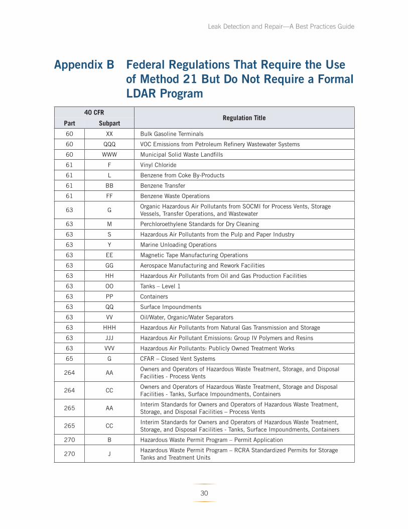
Appendix B Federal Regulations That Require the Use of Method 21 But Do Not Require a Formal LDAR Program
40 CFR Regulation Title
Part Subpart
60 XX Bulk Gasoline Terminals
60 QQQ VOC Emissions from Petroleum Refinery Wastewater Systems
60 WWW Municipal Solid Waste Landfi lls
61 F Vinyl Chloride
61 L Benzene from Coke By-Products
61 BB Benzene Transfer
61 FF Benzene Waste Operations
63 G Organic Hazardous Air Pollutants from SOCMI for Process Vents, Storage
Vessels, Transfer Operations, and Wastewater
63 M Perchloroethylene Standards for Dry Cleaning
63 S Hazardous Air Pollutants from the Pulp and Paper Industry
63 Y Marine Unloading Operations
63 EE Magnetic Tape Manufacturing Operations
63 GG Aerospace Manufacturing and Rework Facilities
63 HH Hazardous Air Pollutants from Oil and Gas Production Facilities
63 OO Tanks – Level 1
63 PP Containers
63 QQ Surface Impoundments
63 VV Oil/Water, Organic/Water Separators
63 HHH Hazardous Air Pollutants from Natural Gas Transmission and Storage
63 JJJ Hazardous Air Pollutant Emissions: Group IV Polymers and Resins
63 VVV Hazardous Air Pollutants: Publicly Owned Treatment Works
65 G CFAR – Closed Vent Systems
264 AA Owners and Operators of Hazardous Waste Treatment, Storage, and Disposal
Facilities - Process Vents
264 CC Owners and Operators of Hazardous Waste Treatment, Storage and Disposal
Facilities - Tanks, Surface Impoundments, Containers
265 AA Interim Standards for Owners and Operators of Hazardous Waste Treatment,
Storage, and Disposal Facilities – Process Vents
265 CC Interim Standards for Owners and Operators of Hazardous Waste Treatment,
Storage, and Disposal Facilities - Tanks, Surface Impoundments, Containers
270 B Hazardous Waste Permit Program – Permit Application
270 J Hazardous Waste Permit Program – RCRA Standardized Permits for Storage
Tanks and Treatment Units
30
Leak Detection and Repair—A Best Practices Guide
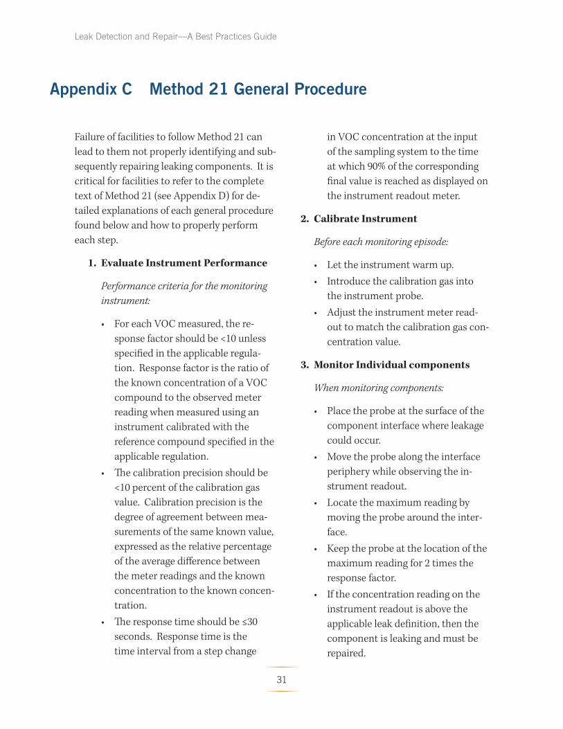
Appendix C Method 21 General Procedure
Failure of facilities to follow Method 21 can
lead to them not properly identifying and sub
sequently repairing leaking components. It is
critical for facilities to refer to the complete
text of Method 21 (see Appendix D) for de
tailed explanations of each general procedure
found below and how to properly perform
each step.
1. Evaluate Instrument Performance
Performance criteria for the monitoring
instrument:
• For each VOC measured, the re
sponse factor should be <10 unless
specified in the applicable regula
tion. Response factor is the ratio of
the known concentration of a VOC
compound to the observed meter
reading when measured using an
instrument calibrated with the
reference compound specified in the
applicable regulation.
• The calibration precision should be
<10 percent of the calibration gas
value. Calibration precision is the
degree of agreement between mea
surements of the same known value,
expressed as the relative percentage
of the average diff erence between
the meter readings and the known
concentration to the known concen
tration.
• The response time should be ≤30
seconds. Response time is the
time interval from a step change
in VOC concentration at the input
of the sampling system to the time
at which 90% of the corresponding
final value is reached as displayed on
the instrument readout meter.
2. Calibrate Instrument
Before each monitoring episode:
• Let the instrument warm up.
• Introduce the calibration gas into
the instrument probe.
• Adjust the instrument meter read
out to match the calibration gas con
centration value.
3. Monitor Individual components
When monitoring components:
• Place the probe at the surface of the
component interface where leakage
could occur.
• Move the probe along the interface
periphery while observing the in
strument readout.
• Locate the maximum reading by
moving the probe around the inter
face.
• Keep the probe at the location of the
maximum reading for 2 times the
response factor.
• If the concentration reading on the
instrument readout is above the
applicable leak definition, then the
component is leaking and must be
repaired.
31

Leak Detection and Repair—A Best Practices Guide
Appendix D Method 21—Determination of Volatile Organic Compound Leaks
1.0 Scope and Application
1.1 Analytes.
Analyte CAS No.
Volatile Organic Compounds (VOC)………. No CAS number assigned.
1.2 Scope. This method is applicable for the
determination of VOC leaks from process
equipment. These sources include, but are not
limited to, valves, flanges and other connec
tions, pumps and compressors, pressure relief
devices, process drains, open-ended valves,
pump and compressor seal system degas
sing vents, accumulator vessel vents, agitator
seals, and access door seals.
1.3 Data Quality Objectives. Adherence to the
requirements of this method will enhance the
quality of the data obtained from air pollutant
sampling methods.
2.0 Summary of Method
2.1 A portable instrument is used to detect
VOC leaks from individual sources. Th e
instrument detector type is not specifi ed, but
it must meet the specifications and perfor
mance criteria contained in Section 6.0. A
leak definition concentration based on a
reference compound is specified in each ap
plicable regulation. This method is intended
to locate and classify leaks only, and is not to
be used as a direct measure of mass emission
rate from individual sources.
3.0 Defi nitions
3.1 Calibration gas means the VOC com
pound used to adjust the instrument meter
reading to a known value. The calibration gas
is usually the reference compound at a known
concentration approximately equal to the
leak defi nition concentration.
3.2 Calibration precision means the degree
of agreement between measurements of the
same known value, expressed as the relative
percentage of the average diff erence between
the meter readings and the known concentra
tion to the known concentration.
3.3 Leak definition concentration means the
local VOC concentration at the surface of a
leak source that indicates that a VOC emis
sion (leak) is present. The leak definition is an
instrument meter reading based on a refer
ence compound.
3.4 No detectable emission means a lo
cal VOC concentration at the surface of a
leak source, adjusted for local VOC ambient
concentration, that is less than 2.5 % of the
specified leak definition concentration. Th at
indicates that a VOC emission (leak) is not
present.
32

Leak Detection and Repair—A Best Practices Guide
3.5 Reference compound means the VOC species
selected as the instrument calibration basis for
specification of the leak defi nition concentration.
(For example, if a leak definition concentration is
10,000 ppm as methane, then any source emission
that results in a local concentration that yields a
meter reading of 10,000 on an instrument meter
calibrated with methane would be classified as a
leak. In this example, the leak defi nition concentra
tion is 10,000 ppm and the reference compound is
methane.)
3.6 Response factor means the ratio of the known
concentration of a VOC compound to the observed
meter reading when measured using an instrument
calibrated with the reference compound specifi ed
in the applicable regulation.
3.7 Response time means the time interval from a
step change in VOC concentration at the input of
the sampling system to the time at which 90 per
cent of the corresponding final value is reached as
displayed on the instrument readout meter.
4.0 Interferences [Reserved]
5.0 Safety
5.1 Disclaimer. This method may involve hazard
ous materials, operations, and equipment. Th is test
method may not address all of the safety problems
associated with its use. It is the responsibility of the
user of this test method to establish appropriate
safety and health practices and determine the ap
plicability of regulatory limitations prior to per
forming this test method.
5.2 Hazardous Pollutants. Several of the com
pounds, leaks of which may be determined by this
method, may be irritating or corrosive to tissues
(e.g., heptane) or may be toxic (e.g., benzene, methyl
alcohol). Nearly all are fire hazards. Compounds in
emissions should be determined through familiar
ity with the source. Appropriate precautions can
be found in reference documents, such as reference
No. 4 in Section 16.0.
6.0 Equipment and Supplies
A VOC monitoring instrument meeting the follow
ing specifications is required:
6.1 The VOC instrument detector shall respond to
the compounds being processed. Detector types
that may meet this requirement include, but are
not limited to, catalytic oxidation, fl ame ionization,
infrared absorption, and photoionization.
6.2 The instrument shall be capable of measuring
the leak definition concentration specified in the
regulation.
6.3 The scale of the instrument meter shall be
readable to ±2.5 % of the specified leak defi nition
concentration.
6.4 The instrument shall be equipped with an
electrically driven pump to ensure that a sample
is provided to the detector at a constant fl ow rate.
The nominal sample flow rate, as measured at the
sample probe tip, shall be 0.10 to 3.0 l/min (0.004 to
0.1 ft 3 /min) when the probe is fitted with a glass
wool plug or filter that may be used to prevent
plugging of the instrument.
6.5 The instrument shall be equipped with a probe
or probe extension or sampling not to exceed 6.4
mm ( 1/4 in) in outside diameter, with a single end
opening for admission of sample.
33
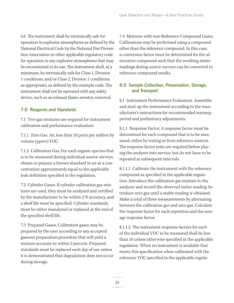
Leak Detection and Repair—A Best Practices Guide
6.6 The instrument shall be intrinsically safe for
operation in explosive atmospheres as defined by the
National Electrical Code by the National Fire Preven
tion Association or other applicable regulatory code
for operation in any explosive atmospheres that may
be encountered in its use. The instrument shall, at a
minimum, be intrinsically safe for Class 1, Division
1 conditions, and/or Class 2, Division 1 conditions,
as appropriate, as defined by the example code. Th e
instrument shall not be operated with any safety
device, such as an exhaust flame arrestor, removed.
7.0 Reagents and Standards
7.1 Two gas mixtures are required for instrument
calibration and performance evaluation:
7.1.1 Zero Gas. Air, less than 10 parts per million by
volume (ppmv) VOC.
7.1.2 Calibration Gas. For each organic species that
is to be measured during individual source surveys,
obtain or prepare a known standard in air at a con
centration approximately equal to the applicable
leak defi nition specified in the regulation.
7.2 Cylinder Gases. If cylinder calibration gas mix
tures are used, they must be analyzed and certifi ed
by the manufacturer to be within 2 % accuracy, and
a shelf life must be specified. Cylinder standards
must be either reanalyzed or replaced at the end of
the specified shelf life.
7.3 Prepared Gases. Calibration gases may be
prepared by the user according to any accepted
gaseous preparation procedure that will yield a
mixture accurate to within 2 percent. Prepared
standards must be replaced each day of use unless
it is demonstrated that degradation does not occur
during storage.
7.4 Mixtures with non-Reference Compound Gases.
Calibrations may be performed using a compound
other than the reference compound. In this case,
a conversion factor must be determined for the al
ternative compound such that the resulting meter
readings during source surveys can be converted to
reference compound results.
8.0 Sample Collection, Preservation, Storage, and Transport
8.1 Instrument Performance Evaluation. Assemble
and start up the instrument according to the man
ufacturer’s instructions for recommended warmup
period and preliminary adjustments.
8.1.1 Response Factor. A response factor must be
determined for each compound that is to be mea
sured, either by testing or from reference sources.
The response factor tests are required before plac
ing the analyzer into service, but do not have to be
repeated at subsequent intervals.
8.1.1.1 Calibrate the instrument with the reference
compound as specified in the applicable regula
tion. Introduce the calibration gas mixture to the
analyzer and record the observed meter reading. In
troduce zero gas until a stable reading is obtained.
Make a total of three measurements by alternating
between the calibration gas and zero gas. Calculate
the response factor for each repetition and the aver
age response factor.
8.1.1.2 The instrument response factors for each
of the individual VOC to be measured shall be less
than 10 unless otherwise specified in the applicable
regulation. When no instrument is available that
meets this specification when calibrated with the
reference VOC specified in the applicable regula
34
Leak Detection and Repair—A Best Practices Guide
tion, the available instrument may be calibrated
with one of the VOC to be measured, or any other
VOC, so long as the instrument then has a response
factor of less than 10 for each of the individual VOC
to be measured.
8.1.1.3 Alternatively, if response factors have been
published for the compounds of interest for the
instrument or detector type, the response factor
determination is not required, and existing results
may be referenced. Examples of published response
factors for flame ionization and catalytic oxidation
detectors are included in References 1–3 of Section
17.0.
8.1.2 Calibration Precision. The calibration preci
sion test must be completed prior to placing the
analyzer into service and at subsequent 3-month
intervals or at the next use, whichever is later.
8.1.2.1 Make a total of three measurements by
alternately using zero gas and the specifi ed calibra
tion gas. Record the meter readings. Calculate the
average algebraic difference between the meter
readings and the known value. Divide this aver
age difference by the known calibration value and
multiply by 100 to express the resulting calibration
precision as a percentage.
8.1.2.2 The calibration precision shall be equal to or
less than 10 % of the calibration gas value.
8.1.3 Response Time. The response time test is re
quired before placing the instrument into service. If a
modification to the sample pumping system or fl ow
configuration is made that would change the response
time, a new test is required before further use.
8.1.3.1 Introduce zero gas into the instrument
sample probe. When the meter reading has sta
bilized, switch quickly to the specifi ed calibration
gas. After switching, measure the time required to
attain 90 % of the final stable reading. Perform this
test sequence three times and record the results.
Calculate the average response time.
8.1.3.2 The instrument response time shall be equal
to or less than 30 seconds. The instrument pump,
dilution probe (if any), sample probe, and probe
filter that will be used during testing shall all be in
place during the response time determination.
8.2 Instrument Calibration. Calibrate the VOC
monitoring instrument according to Section 10.0.
8.3 Individual Source Surveys.
8.3.1 Type I—Leak Definition Based on Concen
tration. Place the probe inlet at the surface of the
component interface where leakage could occur.
Move the probe along the interface periphery while
observing the instrument readout. If an increased
meter reading is observed, slowly sample the inter
face where leakage is indicated until the maximum
meter reading is obtained. Leave the probe inlet at
this maximum reading location for approximately
two times the instrument response time. If the
maximum observed meter reading is greater than
the leak definition in the applicable regulation,
record and report the results as specified in the
regulation reporting requirements. Examples of
the application of this general technique to specifi c
equipment types are:
8.3.1.1 Valves. The most common source of leaks
from valves is the seal between the stem and hous
ing. Place the probe at the interface where the stem
exits the packing gland and sample the stem cir
cumference. Also, place the probe at the interface
of the packing gland take-up flange seat and sample
35
the periphery. In addition, survey valve housings of
multipart assembly at the surface of all interfaces
where a leak could occur.
8.3.1.2 Flanges and Other Connections. For welded
flanges, place the probe at the outer edge of the
flange-gasket interface and sample the circumfer
ence of the flange. Sample other types of nonper
manent joints (such as threaded connections) with
a similar traverse.
8.3.1.3 Pumps and Compressors. Conduct a cir
cumferential traverse at the outer surface of the
pump or compressor shaft and seal interface. If
the source is a rotating shaft, position the probe
inlet within 1 cm of the shaft-seal interface for the
survey. If the housing configuration prevents a
complete traverse of the shaft periphery, sample all
accessible portions. Sample all other joints on the
pump or compressor housing where leakage could
occur.
8.3.1.4 Pressure Relief Devices. Th e confi guration
of most pressure relief devices prevents sampling
at the sealing seat interface. For those devices
equipped with an enclosed extension, or horn,
place the probe inlet at approximately the center of
the exhaust area to the atmosphere.
8.3.1.5 Process Drains. For open drains, place the
probe inlet at approxima tely the center of the area
open to the atmosphere. For covered drains, place
the probe at the surface of the cover interface and
conduct a peripheral traverse.
8.3.1.6 Open-ended Lines or Valves. Place the probe
inlet at approximately the center of the opening to
the atmosphere.
Leak Detection and Repair—A Best Practices Guide
8.3.1.7 Seal System Degassing Vents and Accumula
tor Vents. Place the probe inlet at approximately
the center of the opening to the atmosphere.
8.3.1.8 Access door seals. Place the probe inlet at
the surface of the door seal interface and conduct a
peripheral traverse.
8.3.2 Type II—“No Detectable Emission”. Deter
mine the local ambient VOC concentration around
the source by moving the probe randomly upwind
and downwind at a distance of one to two meters
from the source. If an interference exists with this
determination due to a nearby emission or leak, the
local ambient concentration may be determined
at distances closer to the source, but in no case
shall the distance be less than 25 centimeters. Th en
move the probe inlet to the surface of the source
and determine the concentration as outlined in
Section 8.3.1. Th e difference between these concen
trations determines whether there are no detect
able emissions. Record and report the results as
specified by the regulation. For those cases where
the regulation requires a specific device installa
tion, or that specified vents be ducted or piped to
a control device, the existence of these conditions
shall be visually confirmed. When the regulation
also requires that no detectable emissions exist,
visual observations and sampling surveys are re
quired. Examples of this technique are:
8.3.2.1 Pump or Compressor Seals. If applicable, de
termine the type of shaft seal. Perform a survey of
the local area ambient VOC concentration and de
termine if detectable emissions exist as described
in Section 8.3.2.
8.3.2.2 Seal System Degassing Vents, Accumulator
Vessel Vents, Pressure Relief Devices. If applicable,
36
Leak Detection and Repair—A Best Practices Guide
observe whether or not the applicable ducting or
piping exists. Also, determine if any sources exist in
the ducting or piping where emissions could occur
upstream of the control device. If the required duct
ing or piping exists and there are no sources where
the emissions could be vented to the atmosphere
upstream of the control device, then it is presumed
that no detectable emissions are present. If there
are sources in the ducting or piping where emis
sions could be vented or sources where leaks could
occur, the sampling surveys described in Section
8.3.2 shall be used to determine if detectable emis
sions exist.
8.3.3 Alternative Screening Procedure.
8.3.3.1 A screening procedure based on the forma
tion of bubbles in a soap solution that is sprayed on
a potential leak source may be used for those sourc
es that do not have continuously moving parts, that
do not have surface temperatures greater than the
boiling point or less than the freezing point of the
soap solution, that do not have open areas to the
atmosphere that the soap solution cannot bridge,
or that do not exhibit evidence of liquid leakage.
Sources that have these conditions present must be
surveyed using the instrument technique of Section
8.3.1 or 8.3.2.
8.3.3.2 Spray a soap solution over all potential leak
sources. The soap solution may be a commercially
available leak detection solution or may be pre
pared using concentrated detergent and water. A
pressure sprayer or squeeze bottle may be used to
dispense the solution. Observe the potential leak
sites to determine if any bubbles are formed. If
no bubbles are observed, the source is presumed
to have no detectable emissions or leaks as appli
cable. If any bubbles are observed, the instrument
techniques of Section 8.3.1 or 8.3.2 shall be used
to determine if a leak exists, or if the source has
detectable emissions, as applicable.
37

Leak Detection and Repair—A Best Practices Guide
9.0 Quality Control
Section Quality control measure Effect
8.1.2………………………………… Instrument calibration Ensure precision and accuracy,
precision check. respectively, of instrument
response to standard.
10.0…………………………………. Instrument calibration.
10.0 Calibration and Standardization
10.1 Calibrate the VOC monitoring instrument as
follows. After the appropriate warmup period and
zero internal calibration procedure, introduce the
calibration gas into the instrument sample probe.
Adjust the instrument meter readout to correspond
to the calibration gas value.
Note: If the meter readout cannot be adjusted to
the proper value, a malfunction of the analyzer
is indicated and corrective actions are necessary
before use.
11.0 Analytical Procedures [Reserved]
12.0 Data Analyses and Calculations [Reserved]
13.0 Method Performance [Reserved]
14.0 Pollution Prevention [Reserved]
15.0 Waste Management [Reserved]
16.0 References
1. Dubose, D.A., and G.E. Harris. Response
Factors of VOC Analyzers at a Meter Read
ing of 10,000 ppmv for Selected Organic
Compounds. U.S. Environmental Protection
Agency, Research Triangle Park, NC. Publica
tion No. EPA 600/2–81051. September 1981.
2. Brown, G.E., et al. Response Factors of VOC
Analyzers Calibrated with Methane for
Selected Organic Compounds. U.S. Environ
mental Protection Agency, Research Triangle
Park, NC. Publication No. EPA 600/2–81–022.
May 1981.
3. DuBose, D.A. et al. Response of Portable
VOC Analyzers to Chemical Mixtures. U.S.
Environmental Protection Agency, Research
Triangle Park, NC. Publication No. EPA
600/2–81–110. September 1981.
4. Handbook of Hazardous Materials: Fire, Safety,
Health. Alliance of American Insurers. Schaumberg,
IL. 1983.
17.0 Tables, Diagrams, Flowcharts, and Validation Data [Reserved]
38
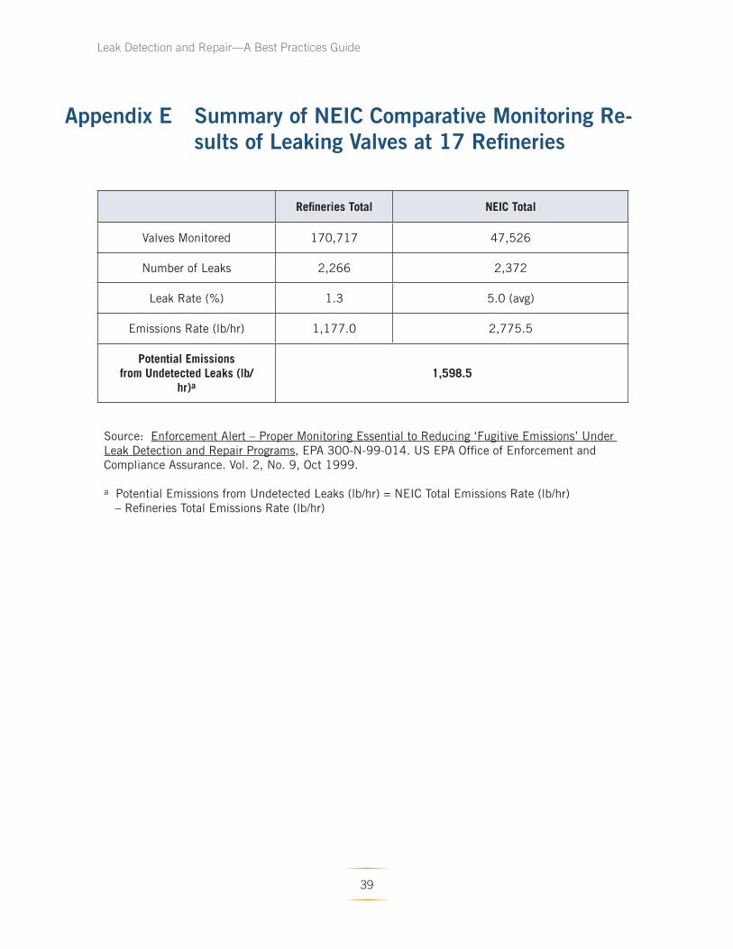
Leak Detection and Repair—A Best Practices Guide
Appendix E Summary of NEIC Comparative Monitoring Results of Leaking Valves at 17 Refi neries
Refineries Total NEIC Total
Valves Monitored 170,717 47,526
Number of Leaks 2,266 2,372
Leak Rate (%) 1.3 5.0 (avg)
Emissions Rate (lb/hr) 1,177.0 2,775.5
Potential Emissions from Undetected Leaks (lb/
hr)a 1,598.5
Source: Enforcement Alert – Proper Monitoring Essential to Reducing ‘Fugitive Emissions’ Under
Leak Detection and Repair Programs, EPA 300-N-99-014. US EPA Office of Enforcement and
Compliance Assurance. Vol. 2, No. 9, Oct 1999.
a Potential Emissions from Undetected Leaks (lb/hr) = NEIC Total Emissions Rate (lb/hr)
– Refineries Total Emissions Rate (lb/hr)
39

Leak Detection and Repair—A Best Practices Guide
Appendix F Enforcement Alert
40
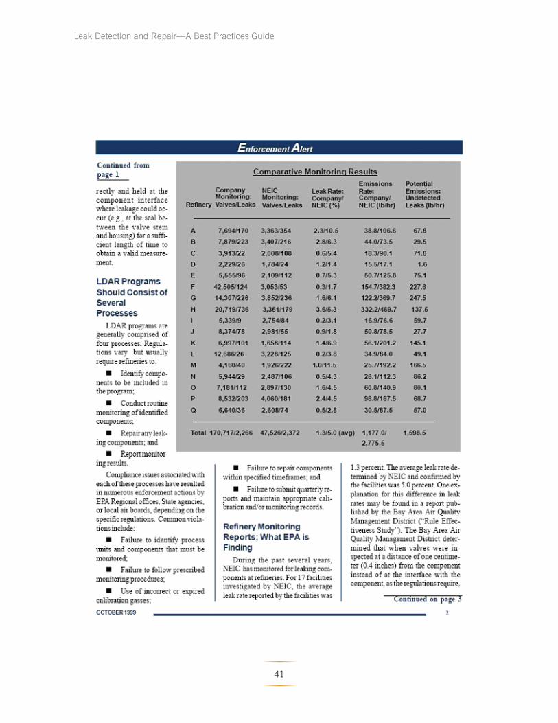
Leak Detection and Repair—A Best Practices Guide
41
Leak Detection and Repair—A Best Practices Guide
42
Leak Detection and Repair—A Best Practices Guide
43

United States
Environmental Protection
Agency
Office of Compliance
Office of Enforcement and Compliance Assurance
(mail code)
EPA-305-D-07-001
October 2007
www.epa.gov/compliance