leading the path towards 5g with lte advanced pro - … the path towards 5g with lte advanced pro...
TRANSCRIPT

Leading the path towards 5G with LTE Advanced Pro
Sanjeev Athalye, Sr. DirectorQualcomm Technologies, Inc.May 2016

2
Progress LTE capabilities towards 5GIn parallel driving 4G and 5G to their fullest potential
Note: Estimated commercial dates. Not all features commercialized at the same time
LTE Advanced ProLTE Advanced
2015 2020+
Rel-10/11/12
Carrier aggregation
Low LatencyDual connectivitySON+
Massive/FD-MIMO
CoMP Device-to-device
Unlicensed spectrum
Enhanced CA
Shared Broadcast
Internet of Things256QAM
V2X
FeICIC
Advanced MIMO
FDD-TDD CA
eLAA
5G

3
5G
LTE Advanced ProLTE AdvancedRel-10/11/12
2015 2020+
Progress LTE capabilities towards 5GIn parallel driving 4G and 5G to their fullest potential
Note: Estimated commercial dates. Not all features commercialized at the same time
• Unified, more capable platform for spectrum bands below/above 6 GHz
• For new spectrum available beyond 2020, including legacy re-farming
• Fully leverage 4G investments for a phased 5G rollout
• Significantly improve cost and energy efficiency
• Further backwards-compatible enhancements
• For spectrum opportunities available before 2020

4
Connect the Internet of Things
New ways to connect and interact New classes
of services
High Performance
Low power/complexity
Digital TV broadcasting
Proximal awareness
Public safety
Evolving LTE-Direct
LTE V2X Communications
Latency-critical control
Proliferate LTE to new use cases
LTE IoT
Extending the value of LTE technology and ecosystem

5
Extending LTE to unlicensed spectrum globally with LAA
1 Assumptions: 3GPP LAA evaluation model based on TR 36.889, two operators, 4 small-cells per operator per macro cell, outdoor, 40 users on same 20 MHz channel in 5 GHz, both uplink and downlink in 5 GHz, 3GPP Bursty traffic model 3
with 1MB file, LWA using 802.11ac, DL 2x2 MIMO (no MU-MIMO), 24dBm + 3dBi Tx power in 5 GHz for LAA eNB or Wi-Fi AP.
• Path to Gbps speedsAggregates licensed and unlicensed spectrum
• 2x capacity and rangeOver Wi-Fi capacity in dense deployments1
• Seamless and robust user experienceWith reliable licensed spectrum anchor
• Single unified LTE networkCommon management
• Fair Wi-Fi coexistence Fundamental design principle
Unlicensed (5 GHz)
Licensed Anchor
(400 MHz – 3.8 GHz)
LTE &(e)LAA
Carrieraggregation
Licensed Assisted Access (LAA) with Listen Before Talk (LBT)
LTE Unlicensed small cell

6
Scaling to connect the Internet of ThingsScaling up in performance and mobility
Scaling down in complexity and power
Wearables
Energy Management
Environment monitoring
Smart buildings
Object Tracking
City infrastructure
Utility metering
Connected healthcare
Video security
Connected car
Mobile
Significantly widening the range of enterprise and consumer use cases
LTE Advanced (Today+) LTE IoT (Release 13+)
LTE Advanced>10 Mbps
n x 20 MHz
LTE Cat-1Up to 10 Mbps
20 MHz
eMTC (Cat-M1)Up to 1 Mbps
1.4 MHz narrowband
NB-IOT (Cat-M2)10s of kbps to 100s of kbps
180 kHz narrowband

7
Our 5G vision: a unifying connectivity fabric
Higher reliability services
Enhancedmobile broadband
Massive Internetof Things
NetworkingMobile devices RoboticsAutomotive Health Smart cities Smart homesWearables
Unified design for all spectrum types and bands from below 1GHz to mmWave
• Lower latency
• Higher reliability
• Higher availability
• Stronger security
• Multi-Gbps data rates
• Highwe capacity
• Uniformity
• Deep awareness
• Lower cost
• Lower energy
• Deeper coverage
• Higher density

8
Scalable across a broad variation of requirements
Wide area Internet of Things
Higher-reliability control
Enhanced mobile broadband
Deeper coverageTo reach challenging locations
Lower energy10+ years of battery life
Lower complexity10s of bits per second
Higher density1 million nodes per sq. km
Enhanced capacity10 Tbps per sq. km
Enhanced data ratesMulti-Gigabits per second
Better awarenessDiscovery and optimization
Frequent user mobilityOr no mobility at all
Stronger securityUsed in health/government/
financial applications
Lower latencyAs low as 1 millisecond
Higher reliability> 99.999% packet success rate
This presentation addresses potential use cases and potential characteristics of 5G technology. These slides are not intended to reflect a commitment to the characteristics or commercialization of any product or service of Qualcomm Technologies, Inc. or its affiliates

9
Diverse spectrum types and bandsFrom narrowband to ultra-wideband, TDD & FDD
Licensed SpectrumCleared spectrumEXCLUSIVE USE
Unlicensed SpectrumMultiple technologies
SHARED USE
Shared Licensed SpectrumComplementary licensing
SHARED EXCLUSIVE USE
Below 1 GHz: longer range, massive number of things
Below 6 GHz: mobile broadband, higher reliability services
Above 6 GHz including mmWave: for both access and backhaul, shorter range
10
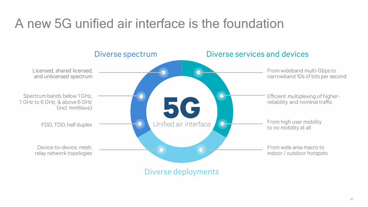
A new 5G unified air interface is the foundation
FDD, TDD, half duplex
Licensed, shared licensed, and unlicensed spectrum
Spectrum bands below 1 GHz, 1 GHz to 6 GHz, & above 6 GHz
(incl. mmWave)
Device-to-device, mesh, relay network topologies
From wideband multi-Gbps to narrowband 10s of bits per second
Efficient multiplexing of higher-reliability and nominal traffic
From high user mobility to no mobility at all
From wide area macro to indoor / outdoor hotspots
Diverse spectrum Diverse services and devices
Diverse deployments
Unified air interface5G
11
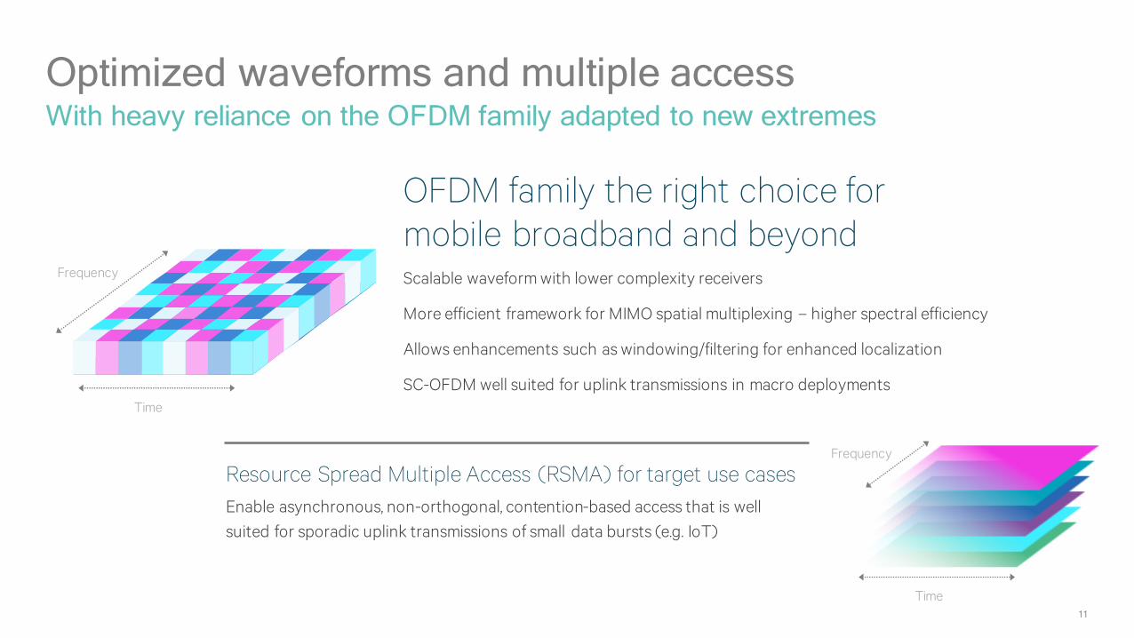
Optimized waveforms and multiple accessWith heavy reliance on the OFDM family adapted to new extremes
OFDM family the right choice formobile broadband and beyondScalable waveform with lower complexity receivers
More efficient framework for MIMO spatial multiplexing – higher spectral efficiency
Allows enhancements such as windowing/filtering for enhanced localization
SC-OFDM well suited for uplink transmissions in macro deployments
Resource Spread Multiple Access (RSMA) for target use casesEnable asynchronous, non-orthogonal, contention-based access that is well suited for sporadic uplink transmissions of small data bursts (e.g. IoT)
Time
Frequency
Frequency
Time

12
Support diverse spectrum bands and bandwidthScalable bandwidth with 2K subcarrier spacing
Sub-carrier spacing = B(extended cyclic prefix)
Outdoor andmacro coverage
FDD/TDD <3 GHz
Indoorwideband
TDD e.g. 5 GHz (Unlicensed) 160MHz bandwidth
Sub-carrier spacing = 8B
mmWaveTDD e.g. 28 GHz
Sub-carrier spacing = 2B(normal cyclic prefix)
Outdoor andsmall cell
TDD > 3 GHz80MHz
500MHz bandwidth
Sub-carrier spacing = 16B
20MHz
• Efficiently address range of available bandwidths, from < 1GHz to >6GHz
• Maximum FFT size, e.g., 4096, leveraged across bands and bandwidths
• Natural scaling of CP with subcarrier spacing
• Address coherence bandwidth and delay spread for different bands & deployments
• Improve processing timeline by front load control/pilot with small symbol granularity for fast HARQ turn-around
Example usage models and channel bandwidths

13
Support diverse latency and QoS requirementsScalable TTI and numerology
TTI
Longer TTI for higher spectral efficiency
Shorter TTI for lower latency
• 2N TTI per 1 ms
- Combination with 2K scalable subcarrier spacing allows nesting of smaller TTI numerologies into larger ones with guaranteed periodic overlap of control
- Other TTI durations via bundling is possible
• Symbol duration = 2-M ms
- Allows finest possible granularity with TTIs scaling down to single symbol
- Benefits low-latency in larger delay spread environments
- Numerology multiplexing further simplified due to alignment every 2M symbols

14
A more flexible framework with forward compatibilityDesigned to multiplex envisioned & unforeseen 5G services on the same frequency
Integrated frameworkThat can support diverse deployment
scenarios and network topologies
Scalable transmission time interval (TTI)For diverse latency requirements — capable of
latencies an order of magnitude lower than LTE
Higher-reliability transmissionsMay occur at any time; design such that
other traffic can sustain puncturing1
Forward compatibilityWith support for blank subframes and frequency
resources for future services / features
1 Nominal 5G access to be designed such that it is capable to sustain puncturing from higher-reliability transmission or bursty interference
Blank subcarriers
Scalable TTI WANBlank subframes
D2D
Multicast

15
Natively incorporate advanced wireless technologiesMany technology enablers to meet 5G requirements and services
Massive MIMO
Coordinated Spatial Techniques
Advanced Receivers
Beamforming
Integrated access and backhaul
mmWave
Across diverse spectrum bands and
types
Multicast
V2X
Full Self-Configuration
Hyper dense deployments
Multi-hop & D2D communications
Low latency & more-reliable communication
More energy efficient, lower cost IoT communications

16
Massive MIMO at 4 GHz allows reuse of existing sitesLeverage higher spectrum band using same sites and same transmit power
Macro site1.7 km inter-site distance46 dBm transmit power
Source: Qualcomm Technologies, Inc. simulations; Macro-cell with 1.7km inter-site distance, 10 users per cell, 46 dBm Tx power at base station, 20MHz@2GHz and 80MHz@4GHz BW TDD, 2.4x Massive MIMO
Significant Capacity GainAverage Cell Throughput = 808 Mbps in 80 MHz
Throughput (Mbps)
3.4x 4.1x
3.9x2.7x
1
0.9
0.8
0.7
0.6
0.5
0.4
0.3
0.2
0.1
10-1 100 101 102 103
CD
F
2x4 MIMO, 20 MHz @ 2 GHz2x4 MIMO, 80 MHz @ 4 GHz
24x4 MIMO, 80 MHz @ 4 GHz10 Users per Cell
Significant Gain in Cell Edge User Throughput

17
Realizing the mmWave opportunity for mobile broadband
Smart beamforming & beam tracking
Increase coverage and minimize interference
Solutions
mmWave
sub6Ghz
Tighter interworking with sub 6 GHz
Increase robustness and faster system acquisition
Phase noise mitigation in RF components
lower cost, lower power devices
The enhanced mobile broadband opportunity The challenge—‘mobilizing’ mmWave • Large bandwidths, e.g. 100s of MHz
• Multi-Gbps data rates
• Flex deployments (integrated access/backhaul)
• Higher capacity with dense spatial reuse
• Robustness results from high path loss and susceptibility to blockage
• Device cost/power and RF challenges at mmWave frequencies
5G

18
Making mmWave a reality for mobileQualcomm Technologies, Inc. is setting the path to 5G mmWave
Qualcomm VIVE is a product of Qualcomm Atheros, Inc.;
^ Based on Qualcomm Technologies Inc. simulations
Qualcomm® VIVE™ 802.11ad technology with a 32-antenna array element
60 GHz chipset commercial today for mobile devices
Developing robust 5G mmWavefor enhanced mobile broadband
0.705 inch
0.28 inch
28 GHz outdoor example with ~150m dense urban LOS and NLOS coverage using directional beamforming^
Manhattan 3D mapResults from ray-tracing^

19
5G standardization for 2020 launch
2016 20212017 2019 2020 20222015 2018
R15 5G WI’s
5G study items
LTE evolution in parallel with 5G
5G phase 2launch
R16 5G WI’s
3GPP RAN workshop
Note: Estimated commercial dates; 1 Forward compatibility with R16 and beyond
R17+5G evolution
5G phase 1launch1
20
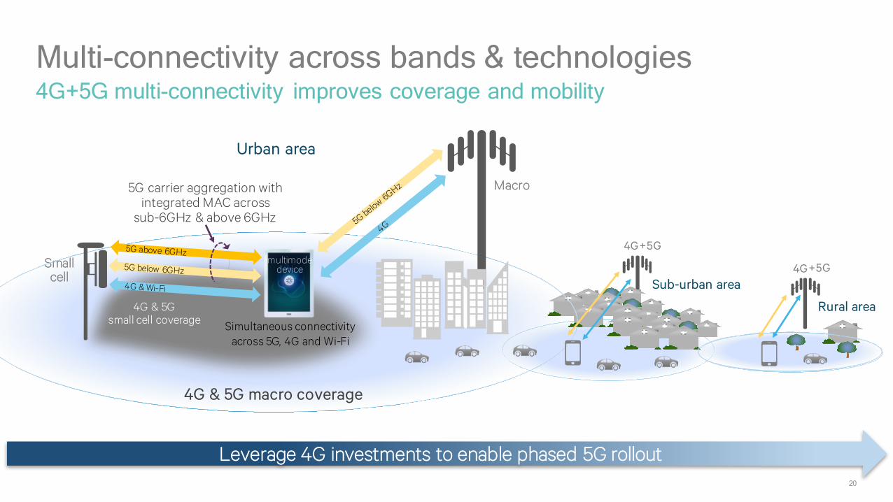
Multi-connectivity across bands & technologies4G+5G multi-connectivity improves coverage and mobility
Rural area
+5G4G
Sub-urban area
Smallcell
Simultaneous connectivityacross 5G, 4G and Wi-Fi
Urban area
4G & 5G macro coverage
Leverage 4G investments to enable phased 5G rollout
+5G4G
4G & 5Gsmall cell coverage
5G carrier aggregation with integrated MAC across
sub-6GHz & above 6GHz
multimode device
Macro
21
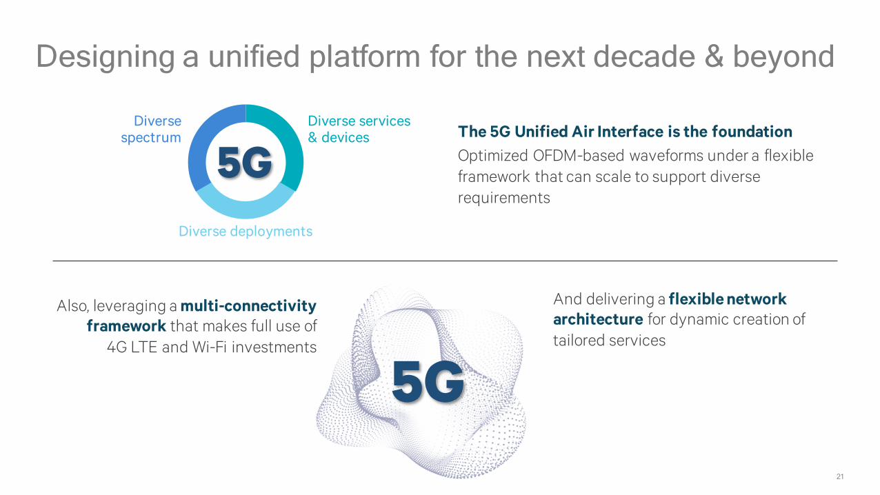
Designing a unified platform for the next decade & beyond
The 5G Unified Air Interface is the foundationOptimized OFDM-based waveforms under a flexible framework that can scale to support diverse requirements
Diverse spectrum
Diverse services & devices
Diverse deployments
Also, leveraging a multi-connectivity framework that makes full use of
4G LTE and Wi-Fi investments
And delivering a flexible network architecture for dynamic creation of tailored services
5G
5G
Thank you
Follow us on:For more information, visit us at: www.qualcomm.com & www.qualcomm.com/blog
Nothing in these materials is an offer to sell any of the components or devices referenced herein.
©2013-2016 Qualcomm Technologies, Inc. and/or its affiliated companies. All Rights Reserved.
Qualcomm, Snapdragon and VIVE are trademarks of Qualcomm Incorporated, registered in the United States and other countries. Other products and brand names may be trademarks or registered trademarks of their respective owners.
References in this presentation to “Qualcomm” may mean Qualcomm Incorporated, Qualcomm Technologies, Inc., and/or other subsidiaries or business units within the Qualcomm corporate structure, as applicable.
Qualcomm Incorporated includes Qualcomm’s licensing business, QTL, and the vast majority of its patent portfolio. Qualcomm Technologies, Inc., a wholly-owned subsidiary of Qualcomm Incorporated, operates, along with its subsidiaries, substantially all of Qualcomm’s engineering, research and development functions, and substantially all of its product and services businesses, including its semiconductor business, QCT.
© 2016 AT&T Intellectual Property. All rights reserved. AT&T and the AT&T logo are trademarks of AT&T
Intellectual Property.
5G: From Concept to Reality May 23, 2016
Arun Ghosh
Director Advanced Wireless Technology Group
AT&T Labs

© 2016 AT&T Intellectual Property. All rights reserved. AT&T and the AT&T logo are trademarks of AT&T Intellectual
Property.
3
Key Drivers to 5G
Massive Connectivity
Throughput & Capacity
Latency
>100 Mbps Everywhere
4K Video
Augmented Reality
Cloud Computing
Industrial Automation
V2V
Sensor Network
Smart Grid
IoT
1000x Traffic
Healthcare
Macro Sub 6GHz
Pico Sub 6GHz
Pico mmWave
Unlicensed mmWave Access
WiFi
10
00
4G
5G

© 2016 AT&T Intellectual Property. All rights reserved. AT&T and the AT&T logo are trademarks of AT&T Intellectual
Property.
4
Key Enablers for 5G
Forward Compatible
• Accommodate new numerology
• Accommodate new frame structure
• Use case specific PHY
Densification
• Self-Backhaul
• Adapts to Transport Requirements
• Energy Efficiency
SDN/NFV
• More open interfaces than LTE
• Separation of control and user plane
Massive Connectivity
• Rel 13 provides a IoT starting point
• Enable future new service classes
• Asynchronous massive connectivity
Multi-Antenna
• Massive MIMO • Active Antenna
• Multiple antenna
models
• MU centric

© 2016 AT&T Intellectual Property. All rights reserved. AT&T and the AT&T logo are trademarks of AT&T
Intellectual Property.
Standardization Aspects of 5G RAT
© 2016 AT&T Intellectual Property. All rights reserved. AT&T and the AT&T logo are trademarks of AT&T Intellectual
Property.
6
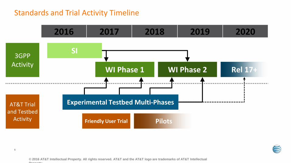
Standards and Trial Activity Timeline
2016 2017 2018 2019 2020
3GPP Activity
SI
WI Phase 1 WI Phase 2
AT&T Trial and Testbed
Activity Friendly User Trial Pilots
Experimental Testbed Multi-Phases
Rel 17+

© 2016 AT&T Intellectual Property. All rights reserved. AT&T and the AT&T logo are trademarks of AT&T Intellectual
Property.
7
Key Components of NR Currently in Standardization
Waveform & Numerology
Frame Structure
FEC Synchronizatio
n & Beam Acquisition
MIMO Framework
and Feedback
Self Backhauling RRC/RRM
NR Specification
Currently being discussed in 3GPP SI Well understood options/choices
Very critical to design these components the right way to have a design that will be future proof (scope of this presentation)
RAN Architecture
Flexible PHY (slicing)

© 2016 AT&T Intellectual Property. All rights reserved. AT&T and the AT&T logo are trademarks of AT&T Intellectual
Property.
8
Forward Looking Design
Flexible UE Specific Numerology
Wide Subcarrier (emBB) Narrow Subcarrier (mMTC) Large CP (Broadcast)
Self Contained Sub-Frames
Sub-Band filtering/windowing is used to mitigate the interference between flexible subcarriers
Each transaction (DL/UL data or measurement) is contained within a sub-frame
DL control DL data Gap UL control (ACK/NACK)

© 2016 AT&T Intellectual Property. All rights reserved. AT&T and the AT&T logo are trademarks of AT&T Intellectual
Property.
9
MIMO Framework
LTE Rel 10 LTE Rel 13 (FD-MIMO) NR Rel 15
8 Tx Fixed codebook Azimuth beamforming SU-MIMO Feedback Explicit RS
16 Tx Reconfigurable codebook Azimuth + Elevation beamforming SU-MIMO Feedback Explicit RS (separable in V and H)
Large number of Tx (128 – 256) Hybrid-beamforming Distributed MIMO Programmable codebook New feedback mechanism (analog)? Azimuth + Elevation beamforming MU-MIMO feedback Scalable and hierarchical RS and beamforming design

• Simplifies transport and increases placement flexibility for ultra-scalable density
• mmWave high resolution beamforming provides a natural isolation of backhaul and access
• Should allow for fast switching and re-routing to mitigate dynamic blocking in mmWave
• L1 design (numerology, RS density, frame structure) can be different for access and backhaul
© 2016 AT&T Intellectual Property. All rights reserved. AT&T and the AT&T logo are trademarks of AT&T Intellectual
Property.
10
Ultra-Dense Self-Backhaul (in-band and out-of-band)
Is self-backhauling the same as relays???
• Multi-hop multi-stage scheduling and QoS control
• Fast (L1 or L2) based switching to support concept such as UE centric virtual cell
• Flow-control on each hop
• Shared cell ID or separate cell ID
L1/L2-hop

• Future proof design (flexible numerology and self contained frame structure)
• Minimize transmission of continuous signal and deliver most signal in a UE specific context
• No predefined timing relationship in the protocol (elastic design for flexible transport capability)
• Hierarchical RAN architecture
© 2016 AT&T Intellectual Property. All rights reserved. AT&T and the AT&T logo are trademarks of AT&T Intellectual
Property.
11
Network Architecture and NFV Readiness
Latency < TTI Latency > TTI RU RU
CU CU
HARQ ACK/NACK HARQ ACK/NACK
Both of these scenarios can exist on the same physical network for
different slices

5G 1 msec
12
eLTE and NR Comparison
• NR is a non-backwards compatible 5G RAT that covers from 600MHz to 100GHz
• LTE will continue to evolves as well (eLTE)
• New features and new interface to the 5G packet core
eLTE 5 msec
5G >100MHz eLTE 20MHz
5G: Yes eLTE: No
5G: flexible eLTE: fixed
Latency
Bandwidth
Connectionless support
L1 Numerology
•Should support UE (or use case) specific L1 (network slicing)
•Should allow for asynchronous UL access (for massive IoT)
•Should allow for arbitrary combination of non contiguous spectrum in L1

© 2016 AT&T Intellectual Property. All rights reserved. AT&T and the AT&T logo are trademarks of AT&T
Intellectual Property.
Trials and Testbed Activities

© 2016 AT&T Intellectual Property. All rights reserved. AT&T and the AT&T logo are trademarks of AT&T Intellectual
Property.
14
AT&T 5G Testbed Development
macro 15GHz + 28GHz
macro + pico 28GHz
macro + pico mmWave + sub 6GHz
2016 Evaluate very basic components of 5G RAT e.g. hybrid beamforming, mmWave, link adaptation & mobility Test simple application such as 4K HD video
Evaluate more complex components such as dynamic TDD, self-backhauling, coordination, CoMP, handoff Test QoS based video and other high bandwidth services
Evaluate 4G/5G co-existence and spectrum sharing, dual connectivity Test new classes of applications such AR/VR, MEC based services, V2X
2017
Planning + Spectrum

Follow us on Twitter @atisupdates www.atis.org/5G2016 Follow us on Twitter @atisupdates www.atis.org/5G2016