leading edge boundary layer suction device
TRANSCRIPT

Leading Edge Boundary Layer Suction Device For the Cal Poly PROVE Rolling-Road Wind Tunnel
Final Design Report
June 2, 2017
Department of Mechanical Engineering California Polytechnic State University, San Luis Obispo
Robert Cabri Daniel Glover Liam Madden
Statement of Disclaimer
Since this project is a result of a class assignment, it has been graded and accepted as fulfillment of the course requirements. Acceptance does not imply technical accuracy or reliability. Any use of information in this report is done at the risk of the user. These risks may include catastrophic failure of the device or infringement of patent or copyright laws. California Polytechnic State University at San Luis Obispo and its staff cannot be held liable for any use or misuse of the project.
ME 428/429/430 Senior Design Project - Final Report 1

Table of Contents
Executive Summary 4
1. Introduction 5
2. Project Background & Research 5 2.1 Boundary Layer Theory and Importance 6 2.2 Existing Methods for Boundary Layer Reduction 7
2.3 WindShear, Inc. 8 2.4 Auto Research Center (ARC) 11 2.5 Honda R&D Americas Wind Tunnel 12
3. Objectives 13 3.1 Customer Requirements 14 3.2 Quality Function Deployment 15 3.3 Engineering Specifications 16
4. Method of Approach 17
5. Management Plan 18
6. Concept Generation 19 6.1 Subsystem Development 22
7. Idea Selection Process 24 7.1 Inlet Subsystem 25 7.2 Ducting Subsystem 26 7.3 Transition Bridge Subsystem 27 7.4 Combinations and Final Decision 28
8. Technical Considerations 29 8.1 Calculations 30
9. Final Design Description 32 9.1 Ducting Subassembly 34 9.2 Framing Subassembly 36 9.3 Lid Subassembly 37
10. Design Considerations 41 10.1 Failure Modes & Effects Analysis 42 10.2 Maintenance Plan 42 10.3 Projected Cost Estimates 43
ME 428/429/430 Senior Design Project - Final Report 2

11. Manufacturing 43 11.1 Plenum Construction 44 11.2 Lid Construction 47 11.3 Device Installation Process 48 11.4 Final Cost Analysis 50
12. Testing & Design Verification Plan 51 12.1 Testing Procedures 51 12.2 Criteria for Completion 52 12.3 Testing and Operational Safety Considerations 52
Appendix A: Quality Function Deployment 54
Appendix B: Project Gantt Chart 55
Appendix C: Bill of Materials 56
Appendix D: Failure Modes and Effects Analysis (FMEA) 57
Appendix E: Design Verification Plan 58
Appendix F: Part & Assembly Drawings 59
Appendix G: Pressure Drop Analysis in EES 82
Appendix H: Plenum Insert Angle Analysis 86
Appendix I: Design Verification Plan & Report 87
Appendix J: Operator’s Manual 91
References 93
ME 428/429/430 Senior Design Project - Final Report 3

Executive Summary Over the course of three quarters from Fall of 2016 to Spring of 2017, our team designed and built a boundary layer suction device. The boundary layer suction device has three main functions: a scoop that redirects most of the boundary layer air out of the wind tunnel, fans that suck the remaining boundary layer air through a porous plate and ducting and out of the wind tunnel, and a transition bridge that transitions the remaining air smoothly onto the rolling road. The wind tunnel is owned by Cal Poly and the rolling road is a new addition to it. By the end of our project, the rolling road was not yet functional. A variable-frequency drive (VFD) will be installed over the summer and belt suction fans will also be installed. Once these are in place, the rolling road can be used. We were successful in building our device and installing it, but once the rolling road is functional, further iterations can be made on our device. The framing and ducting will likely stay in place without further iterations. However, which fans are used can be changed around. We designed our device with an American Fan model AF-10 in mind, but this fan cannot be used until the VFD is installed. There are other fans that can be repurposed and tested on this device as well, though. And, if necessary, a more powerful fan could be purchased. The lid, consisting of the scoop, porous plate, and transition bridge, was also designed to be flexible enough for further iterations. All three of its components are separate pieces that fasten to each other and the lid itself is separate from the rest of the assembly and is only meant to attach to it during tests. Two issues could crop up with the scoop: less air than expected being redirected through the scoop, and the scoop creating flow separation. If the latter issue occurs, a new scoop could be made with the angle (currently 10 degrees) reduced. If the former issue occurs, a new scoop could be made with longer overhang, or ducting could be made from where the flow is redirected, to the end of the tunnel. The following report details the process we went through to make this device. It provides details on the design process, final design analysis, manufacturing results, and test plans that show our progress from project ideation all the way to design acceptance and verification.
ME 428/429/430 Senior Design Project - Final Report 4

1. Introduction Our team consists of Robert Cabri, Daniel Glover, and Liam Madden, three senior Mechanical Engineering students at California Polytechnic State University (Cal Poly). With interests in fluid dynamics and wind tunnel technologies, we have assisted Cal Poly’s Prototype Vehicles lab (PROVE), supervised by Dr. Graham Doig, which recently acquired rolling road addition to their wind tunnel. This conveyor belt system reduces the amount of boundary layer buildup, a velocity gradient formed as a result of viscous properties in a fluid moving over a surface, as air passes through the test section. The result is more realistic flow conditions that a vehicle would experience on the road. PROVE is a student organization with the intent of developing alternative energy vehicles to break records, such as their current goal of building the world’s fastest solar car. The high performance and aerodynamic research involved requires the most accurate results possible, and the presence of a boundary layer during testing has the potential to negatively affect the lift & drag seen on the test vehicle. While the rolling road prevents the buildup of boundary layer effects within the test section, our group focused our attention on the inlet, just after the initial contraction. As a boundary layer forms approaching the rolling road, we determined a solution that eliminates the insufficient air. In doing so, we have provided PROVE and other aerodynamic-focused clubs with steady air flow that allows their vehicles the most accurate aerodynamic data. As a team, our focus was directed towards the multiple requirements that had to be met to ensure the success of the project. First and foremost, our design was chosen to nearly eliminate the boundary layer effects of air passing through the leading edge of the wind tunnel. We executed this by measuring the height of the boundary layer using probes set at the leading edge of the test section, and allotting the necessary scoop height and power to our suction device to remove that layer. Moving forward from there, our device incorporates a smooth transition from the leading edge of the tunnel onto the rolling road. Any protrusions or sharp changes in the tunnel environment have the potential to cause flow discontinuities which may introduce the boundary layer back into the system. While current boundary layer suction devices do exist, they come with a hefty expense. We have designed our own system with a cost conscious approach and, utilizing our research of similar technologies, provided the Aerospace Department’s wind tunnel with a boundary layer suction device.
2. Project Background & Research One of the most effective ways in which automobile designers evaluate aerodynamic performance of their vehicles is through wind tunnel testing. Wind tunnels allow for engineers to create a controlled environment where tests and measurements can be performed on their vehicles to see how the vehicle reacts to different types of flow conditions. Many of the vehicle design clubs at Cal Poly, such as Formula SAE, Supermileage, PROVE Lab, and more all use some degree of wind tunnel testing to help create the fastest and aerodynamically efficient vehicles for their designated competitions. While the current wind tunnel is proficient at testing scale aircraft and other related models, its stationary floor generates significant boundary layer buildup that interferes with the flow around ground vehicles. While the low-speed wind tunnel is in the process of installing a rolling road to mitigate this problem, it still needs
ME 428/429/430 Senior Design Project - Final Report 5

the floor boundary layer removed from the flow field in order to create a realistic test environment for all users of the wind tunnel. 2.1 Boundary Layer Theory and Importance Before we begin our detailed discussion of removing boundary layer buildup in wind tunnel applications, it is important to understand what a boundary layer is, how it is formed, and why it exists. Boundary layers are thin layers of slow-moving fluid flow that develop near the surfaces of solid bodies that are immersed in the path of the moving fluid. Boundary layers exist due to a phenomenon called the no-slip condition, which states that the fluid velocity directly on the surface of an immersed body is assumed to be zero. This infinitely thin region of zero velocity exists due to the imbalance of the adhesive forces between the fluid and the surface, and the cohesive forces between the fluid molecules themselves[1]. For air moving over any solid surface, the adhesive forces between the air and the surface material are greater than the cohesive forces between nearby air molecules. Thus, the molecules closest to the solid surface will stick to the solid surface, and will have a velocity of zero relative to the surface. The air immediately above the solid surface will have a nonzero velocity, but this velocity will still be less than that of the free stream velocity far from the surface. The flow velocity will continue to increase as you move further from the surface until you reach a point where the flow velocity is within 1% of the given free stream velocity. This point signals the end of the boundary layer and the point where the flow is considered to be in the free stream region.
Figure 1. Boundary layer buildup for flow over a flat plate in laminar and turbulent regimes [1]
Figure 1 shows a visual representation of boundary layer development for flow over a flat surface. As you can see, the flow coming into the test section has a uniform velocity profile, which is a profile in which every single point on the profile has the same velocity magnitude and direction. Once the flow hits the solid surface of the plate, a boundary layer begins to develop just above the plate surface. The velocity on the surface of the plate is given to be zero, and the flow velocity increases as you move away from the surface of the plate. Eventually, you reach a distance of the plate ( ) that signifies the end of the boundary layer, where the fluid velocity is at least 99% of the given free stream velocity (U). This figure also presents two important phenomena in boundary layers that can be relevant to our project. First, the boundary layer for a given free stream velocity takes a certain amount of time before it fully develops a
ME 428/429/430 Senior Design Project - Final Report 6

constant boundary layer thickness. When the flow first reaches the beginning of the solid surface (known as the leading edge), there is no boundary layer height. The boundary layer gets thicker and thicker as you move down the length of the plate, and eventually reaches a point where moving further down the plate has no effect on the boundary layer height (given constant free-stream velocity). Second, laminar and turbulent flows have different boundary layer characteristics, indicating that boundary layer development depends on the type of flow going over the immersed body. Boundary layer flow characteristics can be useful in solving a variety of problems in fluid mechanics. For example, the friction drag experienced by a body immersed in fluid flow can be estimated by measuring the height of the fully-developed boundary layer [1]. The height of the boundary layer is directly proportional to the magnitude of the viscous drag exerted on the body, meaning that the taller the boundary layer is over the surface, the greater the drag experienced by the body. However, in wind tunnel simulations, significant boundary layer buildup can create unrealistic flow conditions for vehicles that travel close to the ground. This is a result of the difference in relative velocity in wind tunnels and on the open road. A car driving on the highway is moving relative to both the air and the ground (assuming zero wind speed). As a result, boundary layers only form on the body of the car and not the road, since the air is not moving relative to the ground. In a wind tunnel, the walls and floor of the tunnel are stationary along with the vehicle model inside. When the wind is blown through the tunnel, it has a nonzero velocity relative to both the inside walls of the tunnel in addition to the moving vehicle. Thus, boundary layers form in places that they normally would not in realistic conditions. If the test vehicle is positioned far enough away from the walls of the tunnel, the boundary layer buildup on those walls wouldn’t have a significant effect on the flow field around the vehicle, as the boundary layers would not be large enough to alter the flow near the vehicle. However, for land vehicles that travel close to the ground, this boundary layer on the bottom surface will produce significantly different aerodynamic effects that can cause the tests to produce unrealistic testing results. 2.2 Existing Methods for Boundary Layer Reduction Many different techniques have been developed for reducing the effects of boundary layer formation on wind tunnel floors. Realistically, the boundary layer itself cannot be 100% eliminated, but can be significantly reduced to the point where it has negligible effects on the flow field near the bottom of the tunnel. Some of these techniques are presented in Figure 2, which was developed for a master’s thesis at Wichita State University [2].
ME 428/429/430 Senior Design Project - Final Report 7
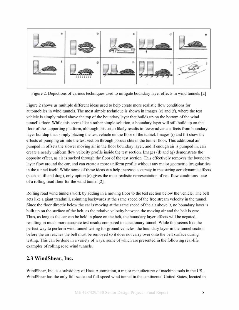
Figure 2. Depictions of various techniques used to mitigate boundary layer effects in wind tunnels [2]
Figure 2 shows us multiple different ideas used to help create more realistic flow conditions for automobiles in wind tunnels. The most simple technique is shown in images (e) and (f), where the test vehicle is simply raised above the top of the boundary layer that builds up on the bottom of the wind tunnel’s floor. While this seems like a rather simple solution, a boundary layer will still build up on the floor of the supporting platform, although this setup likely results in fewer adverse effects from boundary layer buildup than simply placing the test vehicle on the floor of the tunnel. Images (i) and (h) show the effects of pumping air into the test section through porous slits in the tunnel floor. This additional air pumped in offsets the slower moving air in the floor boundary layer, and if enough air is pumped in, can create a nearly uniform flow velocity profile inside the test section. Images (d) and (g) demonstrate the opposite effect, as air is sucked through the floor of the test section. This effectively removes the boundary layer flow around the car, and can create a more uniform profile without any major geometric irregularities in the tunnel itself. While some of these ideas can help increase accuracy in measuring aerodynamic effects (such as lift and drag), only option (c) gives the most realistic representation of real flow conditions - use of a rolling road floor for the wind tunnel [2]. Rolling road wind tunnels work by adding in a moving floor to the test section below the vehicle. The belt acts like a giant treadmill, spinning backwards at the same speed of the free stream velocity in the tunnel. Since the floor directly below the car is moving at the same speed of the air above it, no boundary layer is built up on the surface of the belt, as the relative velocity between the moving air and the belt is zero. Thus, as long as the car can be held in place on the belt, the boundary layer effects will be negated, resulting in much more accurate test results compared to a stationary tunnel. While this seems like the perfect way to perform wind tunnel testing for ground vehicles, the boundary layer in the tunnel section before the air reaches the belt must be removed so it does not carry over onto the belt surface during testing. This can be done in a variety of ways, some of which are presented in the following real-life examples of rolling road wind tunnels.
2.3 WindShear, Inc. WindShear, Inc. is a subsidiary of Haas Automation, a major manufacturer of machine tools in the US. WindShear has the only full-scale and full-speed wind tunnel in the continental United States, located in
ME 428/429/430 Senior Design Project - Final Report 8

Concord, NC [3]. Windshear offers testing for professional race teams at free-stream flow speeds of up to 180 miles per hour, which allows for full-speed of testing of all types of racing cars. The WindShear rolling road wind tunnel uses a closed-loop air circulation system, which means the air that is blown through the test section is rerouted and continuously looped through the entire wind tunnel to be used again. The tunnel uses a two-stage boundary layer removal system that sucks the boundary layer out of the bottom of the tunnel before the belt and re-inserts the removed air back into the test section downstream of the rolling belt [3]. For closed-loop systems, any air removed from the wind tunnel must be replaced in order to keep the amount of mass flowing through the tunnel constant at all times. Open-loop tunnels, such as the one on Cal Poly’s campus, do not need to replace the air sucked out ahead of the rolling road since the air that is blown through the test section is vented into the open atmosphere after it is used. Being a privately-owned organization, WindShear has not publicly released any major design details on the boundary layer suction present on their wind tunnel. However, SAE International (Society of Automotive Engineers) has published multiple articles on the WindShear tunnel for use in academia and associated aerodynamic research. Some technical specifications have been gathered from one of these articles, and the findings are presented in the Table 1.
Table 1. Performance characteristics of the WindShear rolling road wind tunnel [4]
Parameter Specification Actual Measurements
Boundary Layer Thickness
u/U ≥ 0.96 for 0"≤ z ≤ 2"
u/U ≥ 0.995 for 2"< z ≤ 10"
*on centerline in the test plane
u/U ≥ 0.99 for 0"≤ z ≤ 2" (at 180 mph)
u/U ≥ 0.995 for 2"< z ≤ 10" (at 180 mph) *at the test plane on the belt centerline
From Table 1, you can see that the boundary layer on the rolling road for the WindShear tunnel is essentially non-existent. The air velocity at any point between zero and two inches above the surface of the belt is at least 99% of the free stream velocity at 180 mph operation, which is more than satisfactory for the desired specification. As previously mentioned, the WindShear tunnel uses a two-stage boundary layer removal system to reduce the boundary layer height to the specifics detailed in Table 1. The first stage of the boundary layer removal system is a suction scoop that has been sized and calibrated to remove the boundary layer through the inlet and sections upstream of the belt. As the air travels through the tunnel, the boundary layer on the floor of the settling chamber and contraction nozzle (the two areas that precede the test section of the wind tunnel) grows over time as the air reaches the rolling road. The initial scoop removes nearly all of that air and routes it through tubing to release in the diffuser downstream of the rolling road [4]. An image of this suction scoop is provided in Figure 3.
ME 428/429/430 Senior Design Project - Final Report 9

Figure 3. Primary suction scoop for WindShear rolling road wind tunnel
While the primary scoop does remove nearly all of the boundary layer buildup upstream of the tunnel, there is a small amount of buildup that appears on the small area of the floor between the scoop and the leading edge of the rolling road. This boundary layer needs to be removed as well, as the new layer can have significant aerodynamic impacts on the test vehicle. This second removal stage is done with two suction ducts immediately in front of the rolling road, where the remaining boundary layer is sucked out of the test section and combined with the original scoop’s removed air to be exhausted downstream of the tunnel. A closer image of these two suction ducts is presented in Figure 4.
ME 428/429/430 Senior Design Project - Final Report 10

Figure 4. 2nd stage tangential suction slots [4]
2.4 Auto Research Center (ARC) Another company that has designed a functional closed-loop rolling road wind tunnel is Auto Research Center, or ARC for short. This wind tunnel, located in Indianapolis, IN, differs from the WindShear tunnel in that it’s not a full-size tunnel: real-time testing is performed on scale models up to 50% of the size of the actual car. While this is not technically as accurate as working with the actual vehicles themselves, well designed models should produce proper results that can then be scaled up to estimate the forces on the actual car itself. The tunnel is powered by a 120 kW drive motor and has a maximum speed of 50 m/s, or just under 112 mph. [5] Like the WindShear tunnel, ARC’s wind tunnel contains a suction device upstream of the rolling road to suck air out of the boundary layer before it reaches the belt of the rolling road. Unfortunately, no specifics are given in regards to the design of the suction device itself, but ARC’s website does state that it uses a 80 kW motor to power the suction device. The airflow velocity at a height of 1 mm above the rolling road is 99% of the free stream flow speed, indicating that the boundary layer over the rolling road during operation is less than 1 mm [5]. Nearly all racing cars have a ride height significantly larger than 1 mm, so it can be assumed that this level of boundary layer reduction is acceptable for accurate testing purposes.
Figure 3. Scale model for wind tunnel testing at ARC [5]
Figure 3 shows a physical test at ARC of a 50% scale open-wheel race car on their rolling road wind tunnel. The car is secured in place by a support wing that mounts to the middle of the car. The wing design is used in order to have as little effect on the flow field around the car, as a simple cylindrical rod can create enough of a disturbance of the airflow downstream of the support that can significantly alter testing
ME 428/429/430 Senior Design Project - Final Report 11

results. This is different from the WindShear tunnel, which uses arm supports that mount directly onto the 4 wheel hubs on the car [5]. 2.5 Honda R&D Americas Wind Tunnel
Honda owns a fully-operational rolling road wind tunnel for testing on the various passenger cars by the Honda R&D Americas division. The tunnel, called the Scale Model Wind Tunnel (SWT), is located in Raymond, Ohio, and has been in operation since 1984 [6]. Like the two previously mentioned tunnels, the Scale Model Wind Tunnel is a closed-loop testing system that recycles air used to test the aerodynamic performance of the vehicles in the tunnel. The tunnel can test car models up to 50% the size of their real-life counterparts, and can test in speeds of up to 155 mph. [6] The boundary layer removal system is similar to the one used in the WindShear tunnel, but uses a different type of two-stage removal system. The first stage is an adjustable height scoop mechanism that removes the boundary buildup upstream of the rolling road, just like in the WindShear tunnel. However, the second stage of the removal system is a combination suction/blowing device that removes any residual boundary layer buildup after the scoop and blows extra air into the free stream at the desired air velocity to even out the flow over the belt. This additional blowing mechanism is not required to get desired results, but does help prevent any adverse pressure gradients from forming in the tunnel that can cause undesirable aerodynamic effects [6]. Figure 4 shows the Honda wind tunnel boundary layer removal system.
Figure 5. Honda Scale Model Wind Tunnel two-stage boundary layer removal system
Given these above examples, there are plenty of possible approaches in designing a successful boundary layer removal system. In an interview with our faculty sponsor, Dr. Graham Doig, multiple practical
ME 428/429/430 Senior Design Project - Final Report 12
approaches to designing this device have already been discussed. First, Dr. Doig specified that the major need for this project will be the near elimination of the boundary layer buildup directly upstream of the belt’s leading edge. This can be done with a suction device similar to both of the previously mentioned wind tunnel systems, and can use similar style fans scaled to meet the requirements of the tunnel when operational. Additionally, our team has been instructed that some form of permeable medium be used to cover the transition between the suction duct and the tunnel test section to prevent any aerodynamic irregularities from forming downstream of the suction duct. This can be accomplished with multiple different parts, such as a porous plate, a wire mesh, or any other material that can allow air to easily pass into the duct. Finally, the wind tunnel needs some sort of transition bridge between the rolling road and the suction duct. This can be a rigid flap, a brush, or some other material that will fill the void between the edge of the duct and the leading edge of the rolling belt. It will have to last a long time, and cannot wear the belt enough to cause failure in the belt. Our design considerations for these customer needs will be addressed in a future design review after this project proposal has been accepted.
3. Objectives The main goal of our project is to remove the boundary layer immediately upstream of the rolling road. This will be an important step toward the rolling road eventually being fully functional. We came up with the following objectives that make up the specifics of our overall goal:
1) A Variable Frequency Drive (VFD) needs to be installed in the rolling road wind tunnel in order to provide power to the system. This particular device is not in the scope of our project, but will dictate what type of electric power we can use to power the suction device and for how long.
2) A suction device will need to be installed immediately upstream of the rolling road to remove the already developed boundary layer before it reaches the belt’s leading edge.
3) A viable transition bridge will need to be installed to cover the gap between the belt’s leading edge and the boundary layer suction device. This transition bridge will form a protective seal that will keep the airflow uniform and prevent any unwanted disturbances from forming.
4) The air removed from the test section through the boundary layer suction device needs to be re-routed somewhere safe and to a location that will not adversely affect the airflow in the rest of the tunnel.
There are up to two 1.5 hp fans available for us to use as well as a 2 hp fan with a VFD from the mini-wind tunnel. The details of Dr. Doig’s requirements as well as the engineering specifications for meeting them are detailed in the following sections. 3.1 Customer Requirements We met with Dr. Doig to learn more about the requirements he had for how these objectives should be met. Some of these requirements are more important than others, and some are more easily measureable than others, but they are all points to be taken into consideration. The requirements are:
ME 428/429/430 Senior Design Project - Final Report 13

● Our design needs to be easy to upgrade and add improvements to since the rolling road is not yet
up and running. If our device is able to work at various wind speeds, then it can be fine-tuned and adjusted as more tests are done.Thus, Dr. Doig needs to be able to easily make changes to it. This requires a simple design.
● The parts used for the project must be easily reproduced or recreated. Likely, different parts of the design will need to be replaced, especially the transitional bridge. Since the transitional bridge will be in contact with the rolling road, it will wear down over time. Thus, it is necessary that this part can be easily replaced.
● It is important that this device is not expensive since it is going to need adjustments and maintenance. If possible, we should use the existing fans mentioned above, rather than purchasing new ones, since this would greatly reduce the cost of this project.
● The wind tunnel is also already existing and is fully functioning, so it is important that our project fits within the already existing conditions, including size constraints. There is a very specific portion of the wind tunnel that our device has to fit in.
● As for the actual device, it has to work at different wind speeds. “Working” means that the suction device suctions air away through ducting, the transitional zone does not form additional discontinuities or allow a boundary layer to reform, and that there is considerably reduced boundary layer at the point where the transitional zone ends and the rolling road begins.
The latter two needs are especially important as they most clearly satisfy the main goal of our project. The scope of our project is primarily the analysis and design of this device. Of course, we will also work on the testing and manufacture of it, but as there are other test and manufacture steps being taken parallel to our own project’s, small tasks can be assigned to wind tunnel volunteers to assist us with issues immediately related to the wind tunnel. 3.2 Quality Function Deployment We used a Quality Function Deployment (QFD) diagram (Appendix A) to turn these requirements into measurable specifications. However, since our project is straightforward, although technical, the translation from requirements to specifications is also straightforward. We looked at what quantitative measurements we could make that would indicate our project meets the requirements. For example, how do we decide if the existing fans are compatible with our design? We can do this by looking at the fan curves, which show the pressure as a function of the volumetric flowrate. Since reduced boundary layer thickness at the leading edge of the rolling road is a requirement, we want to specify that all air more than 1 mm above the rolling road at its leading edge has at least 99% of the freestream velocity. That is, it is an engineering specification that the boundary layer, after our device, is less than 1 mm in height. From this, we can calculate the amount of air that must be redirected through our device. We also made it an engineering specification that the overall pressure drop associated with the redirected air moving
ME 428/429/430 Senior Design Project - Final Report 14

through our device to the inlet of the fan is less than 2 in.w.g. This gives us a flowrate and pressure that we can compare to the fan curves associated with the existing fans. This is essentially a go/no go criteria, since the existing fans either will or will not be able to achieve this. If they are not able to then we will have to purchase a better suited fan. Of course, these specifications are meant to encompass every possible wind speed, and so only correspond with the most difficult wind speed to remove boundary layer at. However, we will measure the boundary layer at 40, 60, 80, and 100 mph and calculate these values for each of the speeds, so that the fan speed can be set accordingly. The specifications for the size constraints were easily measured. The inside of the wind tunnel is 45.5 inches wide and 34.5 inches tall. There are 40 inches of clearance below it. The rolling road is only an inch or so beyond it, but can be moved up to 12 inches away. The rolling road is actually wider than the wind tunnel but will be trimmed to the right width. Our device should remove boundary layer and transition to the rolling road across the whole inner width of the wind tunnel. So, our device should be at most 12 inches long and at most 40 inches tall. It should ideally be 45.5 inches wide. Since the available fans are 1.5 hp each and we should use at most two of them, this gives us a maximum power of 3 hp. For the ease and adaptability of our design, we decided that using more than 90% stock parts should be a specification. Specifically, for the transitional zone, we decided that it should last at least a year before needing replacement and that at most it should deflect .01 mm in order to prevent adverse flow effects. 3.3 Engineering Specifications
Table 2. Engineering Specifications
Description Target Tolerance Risk Compliance
Length 12” Max H I
Width 35” Max H I
Height 40” Max H I
Boundary Layer Height 1/16” Max H A, T
Pressure Drop 4 in.w.g. Max H A, T
Transitional Zone Life 1 yr Min L A
Percent Stock Parts 90% Min L I
ME 428/429/430 Senior Design Project - Final Report 15

Power 3 hp Max M A
Table 2 shows the details of our engineering specifications. It includes the measurable target for each, whether the tolerance is a maximum or minimum, and what the risk and compliance are. The risk can be low, medium, or high and indicates our ability to meet the specification. The compliance can be analysis, testing, similarity, or inspection and indicates how the specification will be found to comply or not. As can be seen in Table 2, the highest risk specifications are the dimensions, boundary layer height, and pressure drop. Our project has to fit within the bounds of the already existing wind tunnel and this can be easily measured with a ruler. The compliance of most of our specifications will be found through analysis. The dimensions and percent stock parts will of course be found through inspection. The boundary layer is something we will measure immediately upstream of our device and also immediately downstream of this. This will give us a very clear measurement of whether our device succeeded. The pressure drop can also be experimentally measured by measuring the pressure on either side of different possible inlets. However, there are some other considerations that aren’t specified that we will keep in mind as we go through the design process. We will make a table that gives a fan speed to set the fan to for wind speeds of 40, 60, 80, and 100 mph. The amount of detail in this table can always be improved because, in actuality, the wind tunnel can run at many more speeds in between the ones that we will provide information for. However, our scope is just to evaluate these four wind speeds, and other wind speeds can then be interpolated from them. The current plan is to duct the removed air out of the wind tunnel and into the room. This will be noisy but it is allowable since the wind tunnel is already very noisy. A reach goal will be to consider reducing the noise of our device. Using a diffuser at the outlet of our device, for example, is a possible solution to this.
4. Method of Approach At this point in time, we had determined a preliminary design with which to move forward in our senior project. And, as we moved forward into the Critical Design Review phase of the project, we invested much more time and effort into prototyping and performing further tests in the wind tunnel. We gained preliminary boundary layer measurements, and built upon and confirmed this data to adjust our decisions made in PDR. In addition, we started the process of contacting parts vendors to obtain samples that will help in the analysis and refinement of our final design by allowing us to measure pressure differentials across various porous plates, for example. From the design process outlined below, we determined a priority concept with which to move forward. For the remainder of the Fall 2016 quarter, we directed our focus towards creating a more detailed concept. Through our analysis, we determined the best hole size for our porous plate, as well as their cooperation
ME 428/429/430 Senior Design Project - Final Report 16

with scoop height to remove an ideal amount of boundary air. In doing so, we pinpointed specific materials and vendors who we intended to order from. At the completion of the project, when we have proper ducting, we can begin testing various configurations of our device. What we will be looking for is how well they remove the boundary layer. We will have to make our system as airtight as possible and figure out how best to attach it to the floor and wind tunnel, which will make use of the existing 8020 frame. We will also test various transitional bridges to see what produces the smoothest transition to the rolling road. These small iterations within our design will lead to a satisfactory device for Dr. Doig to use. It has also come to our attention that the rolling road has gained additional funding and that it has the potential to be up and running for expo. Should this be true, we will be able to build a full scale, functioning prototype as opposed to a small scale prototype in the miniature wind tunnel. It is our intention to have our design become a usable addition to the rolling road wind tunnel by the time we graduate in mid-June.
5. Management Plan Our project group consists of three senior mechanical engineering students here at Cal Poly: Liam Madden, Daniel Glover, and Robert Cabri. Each of the three members in the group will be responsible for various tasks over the course of the project’s duration, but our group has been organized into the three main positions described below: Treasurer and Secretary: Robert Cabri
● This position will be in charge of managing all group finances during the building and testing phases. This includes approving and ordering all stock parts, researching details on vendors with pricing and part availability, and ensuring that all project propositions remain within the group’s available budget. Additionally, this position will be responsible for recording minutes at all meetings with sponsors, customers, and within the senior project class.
Communications Officer: Daniel Glover
● This position will be in charge of all communications to and from our group. This includes continual communication with our sponsor, part vendors, machine shops on campus, and any other entity that will assist the group to completion of the project. This position will use a shared group email account that can be accessed by anyone in the group at any time, in order for maximum transparency during the project.
ME 428/429/430 Senior Design Project - Final Report 17

Testing and Manufacturing Officer: Liam Madden
● This position will be in charge of all physical testing and manual operations on the project and wind tunnel. This includes arranging and managing wind tunnel boundary layer measurements, performance evaluations of the prototype suction device, and guidance for any manufacturing operations during the building phase of the project.
While each group member has been given specific positions to help guide the project through each step of the process, each member will also have many different tasks to complete for each of the major milestones that will be met from now until project completion in June 2017. Here’s a brief list of some of the major events that will take place during project development.
Table 3. Major Milestones in ME 428/429/430 Project Proposal October 25
Preliminary Design Review November 15
Critical Design Review February 7
Manufacturing and Test Review March 16
Project Hardware Safety Demo May 2
Final Design Review June 2
6. Concept Generation The first step in our project design process was to begin generating ideas on how we were to solve our design problem. While our background research and consultation with our sponsor gave us some preliminary ideas on how to approach the design, our group participated in three separate idea generation sessions that we used in order to help come up with multiple different design directions. These idea generation sessions were structured around the various creative problem solving techniques that were discussed in the lecture portion of our senior project class, ME 428. Some of the methods our group used are presented as follows:
● Brainwriting: This method is similar to brainstorming, but with a special focus on generating as many ideas as quickly as possible in a list format. Each member of the team spent roughly five minutes creating a quick list with as many ideas as they could possibly think of, and passed the list on to the next member after the five minute time window expired. The next member continued the list without any input from the previous member who wrote the list, eliminating any risk of criticism that could inhibit idea generation. The process was completed once each member spent
ME 428/429/430 Senior Design Project - Final Report 18

roughly five minutes on the list, and the ideas were then critiqued and analyzed by the entire group as a whole.
● Brainsketching: This method is almost identical to brainwriting, but uses hand-drawn images
instead of a written list to communicate design ideas. Instead of a list, our team used the dry-erase boards in the library to sketch as many ideas as we could in a five minute window, and we discussed and analyzed the results after the time period was complete.
● SCAMPER: This is a method that focuses on creative design based on seven different action
verbs that the acronym ‘SCAMPER’ represents. The action verbs that guide this idea generation process are as follows:
○ Substitute ○ Combine ○ Adapt ○ Modify ○ Put to other uses ○ Eliminate ○ Rearrange or Reverse
While our group worked with this method, we drew basic sketches for each of those action verbs as they pertained to our project. As an example, one interesting design consideration our group came up with took place during the ‘combine’ phase of this process. After looking again at the WindShear boundary layer removal system, we noticed that the primary suction scoop that removed the first part of the boundary layer and the suction slots downstream of the scoop could be combined into one complete subsystem. We decided that it seems redundant to keep two similar components separate from each other, so one of our design concepts combined the two parts into one cohesive subsystem.
Once our group completed three separate idea generation sessions and recorded the results in our logbooks, we spent a day in class (11/1) creating a physical model of one of our ideas for the system. Using foam board, hot glue, tape, and other various materials supplied to us by our senior project advisor, we created a non-functional prototype of one example of our boundary layer removal system concepts.
ME 428/429/430 Senior Design Project - Final Report 19

Figure 6. Physical mockup of one idea for boundary layer removal system
Figure 6 shows the model that we made in class to represent one of our leading ideas for the boundary layer removal device. The model consists of a scale model of the wind tunnel test section, which is made out of white foam board and hot glue. The rolling road belt is made of black construction paper, and is held in place with two axles at each end that attach to the floor of the rolling road. A porous mesh plate is made out of thin crafting foam, and represents the permeable barrier that allows for boundary layer fluid to be sucked out of the free stream and diverted away from the test section. The transition bridge, a component that forms a smooth path from the suction duct onto the rolling road, is modeled as a single piece of foam board between the suction duct and the leading edge of the road. The ducting system below the test section is not shown in figure 6, but was also formed out of additional sections of foam board. Figure 6 was based off of the sketch in figure 7, which was one of the ideas generated during the SCAMPER idea generation process.
Figure 7. Combination of the porous plate suction duct (plate) and the transition bridge into one single
component generated using SCAMPER
ME 428/429/430 Senior Design Project - Final Report 20

6.1 Subsystem Development After our physical model was built, our next step in the concept generation process was to begin breaking our problem down into separate subsystems. From there, we could begin organizing our prior idea generation sessions into individual areas that would allow us to more effectively evaluate and compare the ideas against each other. After organizing the content that we created during the idea generation sessions, our group decided to focus our further work into three separate subsystems:
● Test Section Floor Modifications : All of the components organized into this section are modifications to the floor of the existing test section in the wind tunnel. These components are the main focus of the overall design, as they are the parts that physically allow for the boundary layer removal upstream of the rolling road. This subsystem had plenty of different ideas and concepts generated for its design, which are listed as follows:
○ Suction Scoop: This component is a small scoop raised above the floor of the wind tunnel.
The scoop can be designed to match the height the boundary layer on the floor at a given wind speed, and is connected to the suction fans through a ducting network below the tunnel. This scoop is similar to what’s seen on the Honda and WindShear rolling road tunnels, where it acts as the first stage to each tunnel’s boundary layer removal system.
○ Permeable boundary: The permeable boundary is a modification to the rolling road wind
tunnel that allows for suction directly through the floor of the tunnel. This allows the existing boundary layer to be removed directly through the permeable boundary through the use of suction fans and ducting. This component was given multiple different design approaches, of which are described as follows:
■ Mesh screen ■ Suction slits (as on the WindShear tunnel) ■ Porous plate (metal or high-strength plastic) ■ Air conditioner screen
● Transition Bridge: The transition bridge is the part that forms the transition between the test
section floor modifications and the rolling road itself. None of the examples of the rolling road wind tunnels in our background research have a dedicated transition bridge, but our wind tunnel needs one in order to prevent any residual boundary layer from forming between the floor modifications and the rolling road. Ideally, this part will be flush with the rolling road, and will be small enough that it won’t create any adverse flow phenomena from forming in the test section. Our ideas for this component are as follows:
○ Bridge flap: This part is essentially the entire transition bridge, but it was listed as an
individual component since multiple ways of mounting the part were discussed during idea generation as well. The transition bridge was agreed upon by our team to be a thin
ME 428/429/430 Senior Design Project - Final Report 21

strip of material formed to the shape of the rolling road. Material choices that serve as possible solutions to this subsystem were generated by our group:
■ Metal (likely aluminum or some other lightweight alloy) ■ Plastic (PVC, polycarbonate, delrin homopolymer ■ Rubber ■ Anti-static brush
Figure 8. CAD model our group designed of the transition flap (with piano hinge mount)
○ Transition flap mount: Multiple ideas were generated to mount the transition flap and hold
it flush with the leading edge of the rolling road. ■ Piano hinge: A piano hinge works similarly to a door hinge, but prevents any
rotation of the flap past a 180 degree angle. If the transition flap is held in place by the piano hinge, it can rest on the surface of the rolling road, and gently make contact and prevent any air from moving under the road or to any other undesirable location. An example of this part is shown in figure 9.
■ Firm fastening/welding: The transition bridge could also be held in place by fasteners or welding, which would form a strong foundation for the transition flap to be held in place with.
Figure 9. Closeup image of a standard piano hinge mount [8]
ME 428/429/430 Senior Design Project - Final Report 22

● Ducting and Fan System: This system creates a path for the removed boundary layer flow to be routed away from the test section for disposal. Since our wind tunnel system is an open loop system (meaning the air used in the tunnel is exhausted into the open atmosphere after use), we are not required to re-route the removed boundary layer air back into the tunnel downstream of the test section after use. Thus, we were given more freedom with our design approach, and we generated the following concepts during our ideation process:
○ Material: The material of the ducting was straightforward.
■ Sheet metal: Most ducting is made out of sheet metal. This would be the easiest to purchase and we could even purchase it not as sheets, but as preformed duct. We can also take sheets that we buy to Paladin Sheet Metal in Paso Robles to have the duct made.
■ PVC: This could potentially be a better option than sheet metal since it is more durable, but it could weigh more as well.
■ Wood: While not the conventional material for ducting applications, this could be a cheap and easily manufacturable option.
○ Inlet Shape: The shape of the inlet is important because it determines the size of the suction area.
■ Straight Rectangular: This would be the easiest option, however, it would not allow for as much suction area. It would need to have room between its sides and the farthest point of the rolling road.
■ Shaped to Rolling Road: This would allow for greater suction area but would be harder to manufacture. Rather than stopping at the farthest point of the rolling road, the sides of the duct could shape in the same direction as the curve of the rolling road.
■ Brush Seal: The wind tunnel already has brush seals installed in it. The downstream side of the ducting could be open and brushes could extend from it to the rolling road, sealing the rolling road as a side, and the transition bridge as part of the ceiling.
7. Idea Selection Process After obtaining a number of concepts through idea generation, we then had to narrow these ideas down to determine which would be the most feasible for our suction device. The idea selection process utilized both system level analysis as well as that of complete concepts, which were a combination of original ideas and industry tested designs. Through the use of our own intuition, decision matrices, and professional guidance from experienced professionals, we were able to narrow down the necessities of our system. Additionally,
ME 428/429/430 Senior Design Project - Final Report 23

the use of professional consultation introduced us to ideas that we would not have thought of, but will perform an integral role in creating a successful system. As a whole, the process occurred in two steps:
● Subsystem Pugh Matrices: Using a decision matrix for each of our three subsystems gave us the opportunity to further organize our thoughts and quantitatively determine which of these ideas would best suit our purposes. Each of our three subsystems (inlet, transition, and ducting) had their own decision matrix, organized such that the concepts lined the top and the criterion for selection dropped down the left side. The concepts to be voted on came directly from our idea generation sessions. Meanwhile, the decision criteria stemmed from the engineering specifications, and represented general benchmarks that the concepts could be stacked against. We set the datums, or baselines, of these decision matrices to be either industry tested systems or the simplest form where this was not applicable.
● Three Full Concepts, One Final: After determining subsystem level concepts, we had the task of
combing them into full-fledged suction device designs. This resulted in the creation of three individual designs, each of which combined elements of out top one to two subsystem ideas in each category. At this point, we did not create another decision matrix to weigh these ideas against each other, but instead sought the advice of professionals who have worked in the wind tunnel field. Their guidance helped us to determine which of our ideas were over or under developed, and what components should be combined to create the best functioning device. After these discussions, we as a team were able to sit down and combine the advice we received with our own intuition to determine which idea was most feasible and effective given our requirements.
7.1 Inlet Subsystem
Table 4. Pugh matrix of inlet concepts
Table 4 shows the Pugh decision matrix for the inlet concepts of our boundary layer suction system, where:
ME 428/429/430 Senior Design Project - Final Report 24

1. Open duct section where air can flow down 2. Parallel slits, inspired by WindShear 3. Porous plate, inspired by All-American Racers 4. Air Scoop 5. Mesh Screen
One of the most crucial elements in our device will be by what method we remove air from the test section for it to be ducted away. This inlet will be composed of multiple elements that work synchronously to pull boundary layer air from the tunnel, leaving stable air to flow over the rolling road. The ideas presented encompass a variety of options which we have elected to pursue, including the use of scoops, porous surfaces, or slotted floors, or a combination of these. These give us the ability to suck or “slice” bad air out of the system before it reaches the rolling road. Through the use of the decision matrix, we can clearly see that a porous plate is our most viable option, with WindShear’s parallel slot option as a backup. Both the porous plate and the parallel slots work on the same concept that as air moves across the plane of the wind tunnel floor, a pressure differential will cause some volume of air to be sucked out. Furthermore, the continuous nature of the porous plate allows it to maintain an even suction surface across it face, unlike the twin slots which have two defined suction points. When looking at the other three ideas, an open duct is not feasible simply because the large open face will cause more flow disturbances than it helps. A lone air scoop has similar potential, as it may take off a small amount of the boundary layer, but there is no device to suck off the rest or prevent it from reforming over the top. Mesh, although cheap and easy, is highly flexible, and would require maintenance to ensure it stays taut and sturdy. 7.2 Ducting Subsystem
Table 5. Pugh matrix of ducting concepts
Table 5 shows the Pugh matrix for the ducting concepts where the columns are as listed:
1. The All-American Racers ducting 2. Wood material and rectangular inlet
ME 428/429/430 Senior Design Project - Final Report 25

3. Sheet metal and rectangular inlet 4. PVC and rectangular inlet 5. Wood material and fit to rolling road 6. Sheet metal and fit to rolling road 7. PVC and fit to rolling road
Of the ideas presented, we will be moving forward with sheet metal ducting as our primary design. We will have to outsource it for manufacturing, but given the sources presented to us by our advisor, Sarah Harding, we believe that this may be done with a minimal financial burden. Additionally, sheet metal ducting as a whole is extremely reliable and sturdy, and having it professionally made will ensure that our system is able to perform for a long time. We will also be having an open duct system due to the fact that our tunnel is open-loop, and it is much easier to exhaust the air than to create more invasions in the tunnel. All-American Racers used a 20 hp fan and had a closed-loop boundary layer removal device. This worked well, but is over designed for the scope of our wind tunnel, and could potentially create more issues by tapping into the wind tunnel downstream. Wood ducting, while sturdy, would be much heavier than sheet metal and could not provide as much of an air tight system. Furthermore, we would have to manufacture it in house, and since any additional leaks would create losses in our suction, this is not the best course of action. We may use PVC as the exhaust for our ductwork, but in creating a plenum at the inlet, it would not be as airtight as needed. 7.3 Transition Bridge Subsystem
Table 6. Pugh matrix of ducting concepts
While simple in nature, the transition bridge plays a crucial role in maintaining the performance of our system. A smooth transition is essential to impeding any further boundary layer effects from taking hold after suction has already occurred. When looking at Table 6, the ideas represented include:
ME 428/429/430 Senior Design Project - Final Report 26

1. A stationary, overhanging plastic sheet 2. A hinged, overhanging plastic sheet 3. A rubber flap 4. A brush 5. An overhanging metal sheet
The clear winner in this decision matrix is the hinged plastic sheet. While comparable in most respects to the stationary sheet, a hinged sheet has a number of benefits, especially the fact that it will remain in constant contact with the rolling road. While this may cause some wear to the belt over time, the constant rubbing of the belt will allow the plastic to wear and remain flush with the road. In other words, we will do some pre-installation preparation, but the contact that the plastic has with the rolling road will “machine” it down to an extremely tight tolerance. A stationary plastic piece would take a lot more preparation, and even then would not be entirely flush with the rolling road, which has the potential to create new flow disturbances. Of the other three ideas that we compared using this matrix, only metal was truly feasible for this project, but while similar to the stationary plastic it would be less cost effective and more difficult to machine. We also could not use the hinged concept for metal given that the road would wear down before the metal, which is an expensive and unnecessary repair. Furthermore, while a rubber flap sits flush to the road as a hinged sheet would, it is flimsy and more expensive than the plastic. The instability and flexibility of the rubber could cause it to shift during wind tunnel testing, creating further flow disturbances. The same may be said for a brush, which is frilly and can move as air blows over it. 7.4 Combinations and Final Decision After determining the subsystem level concepts with which we wanted to move forward, we were able to combine them in three different ways to create full design concepts. Although they utilized similar elements, these three ideas all differed from one another, especially when it came to the inlet section. The first two models were based off of industry tested concepts by All-American Racers and WindShear, with our own adjustments to fit the requirements that we have been slated to meet. The third, and final, concept was a design of our that was agreed upon by John Fabijanic, a Cal Poly professor and ex-employee of All-American Racers. The first idea that we came up with was based off of the All-American Racers boundary layer suction device, which utilized a long permeable surface that would provide a suction-only solution to the problem. Additionally, this concept would utilize a closed-loop ducting system made of circular sheet metal. After being removed at the inlet and passed through the fan, the air would be redirected underneath the rolling road to the other end of the tunnel. At this point, the ducting would move upwards and be reconnected at the end of the test section, pushing the removed air back into the free stream. The transition piece used by this system would be almost identical to the one used by All-American Racers, using a sheet of plastic on a hinge to remain flush to the rolling road.
ME 428/429/430 Senior Design Project - Final Report 27
Our second concept was more related to the WindShear system, and would include a combination of both a scoop and suction period. This suction period would be made up of two tangential slots cut into the same piece of sheet metal used to make the scoop, and after the bulk of the boundary layer is removed, these two slots would pull out any additional boundary layer. After passing over the slots, the transition piece would be made of a heavy rubber flap, extending over the rolling road and ideally remaining flush. The ducting used in this system would be a rectangular PVC plenum connected to the fan which in turn would be open to the environment in this open-loop system. The third and final idea that we will be moving forward with uses parts from both of the previous two with a handful of original differences. It will be using a single piece of perforated plywood with an attached solid air scoop, and has a suction area due to the porous holes. It will also use a hinged delrin transition flap, that will extend to the tangent surface of the rolling road. As the road is used, this delrin sheet will be worn down to a point that it is perfectly flush with the road and has an extremely tight tolerance. Ducting for this system will use rectangular sheet metal for durability and stability, and will be exhausted to the open air. We reached the decision for this design after consultation with John Fabijanic, who insisted that it was necessary to have a scoop along with the porous plate. Given that we will only be using one to two 1.5-HP fans, a perforated sheet alone will not reduce enough of the boundary layer. A scoop will assist in directing a portion of the airflow away from the test section, resulting in a preliminary reduction of boundary layer that can be eliminated further over the porous plate. Additionally, Professor Fabijanic was extremely supportive of the use of a hinged flap, as it will provide a surface that is both smooth and extremely flush to the surface of the rolling road. After consideration of his professional feedback, we convened and determined that of our three ideas, this would be the most effective design. One piece that we had not previously considered, but will adding in after our discussions with John Fabijanic is an anti-static brush off of the ducting below the transition bridge. As the rolling road moves on the underside, it pushes air with it and as a result builds up its own boundary layer. For our suction device to properly work, this boundary layer will have to be removed prior to the belt moving onto the top side. As such, this anti-static brush will create a barrier that prevents air from being pushed out the top, eliminating the effects of the scoop and suction before.
8. Technical Considerations So far, we have described the process we went through to reach our final concept design. However, there were still details within this concept that required more detailed description before we could move forward with feasibility analysis. Thus, we will summarize the details of our final design, repeating some of the details, clarifying some, and submitting new ones. For the porous plate we decided it would be best to use perforated plywood, as it is easy to work with. We will order samples of multiple products and decide on one. The solid scoop will be constructed from one piece of lumber, and can be manually mounted to the porous plate. The rolling road can be raised the same amount as this sheet so that our device is flush with the rolling road. This will prevent the possibility of flow separation. The transition to the rolling road will be made of plastic, such as delrin or ABS plastic.
ME 428/429/430 Senior Design Project - Final Report 28

We will machine it to fit snugly on the rolling road. Since it is plastic, it will wear to fit the shape of the rolling road even better. It is also sturdy enough to stay rigid. Since we only have one foot of length to work with, we will design the assembly to fit in this designated space and allow for a small area for the solid scoop to exhaust some of the removed boundary layer. The transition bridge will be an inch or two long since it will be extending out onto the rolling road. We will connect the transition bridge to the porous plate with a piano hinge. The porous plate will be connected directly to the ducting. The ducting will be made of sheet metal and have an inlet that is shaped to fit closely with the rolling road to maximize the length available for suction. We will have a non-static brush attached to the ducting that will be sealed against the rolling road to prevent any air from being pushed into the wind tunnel from below. The height of the scoop will be fixed. The Honda wind tunnel had an adjustable scoop so that it could be set to the height of the boundary layer, leaving the slots to remove the rest of the boundary layer buildup. Since we will have a perforated sheet for suction instead of just tangential slots, we will be able to remove more air with it. Thus, we can set our scoop height to a value that removes a large percentage of the boundary layer at any speed, and then the rest of the air can go through the perforated sheet. We plan on using a single American Fan model AF-10 1.5 hp fan, of which is already owned by the aerospace engineering department. All of these design decisions, though not set in stone, give us the specificity we need in order to analyze the feasibility of our design. We will analyze it from both an engineering and cost standpoint.
8.1 Calculations In order to test whether our device is capable of removing sufficient boundary layer, we had to make some critical assumptions. Part of the boundary layer is removed by the scoop, and the rest must be removed through the perforated plywood. We assumed that the pressure drop across this sheet was greater than any other pressure drops, and that the system curve reflected this pressure drop.
ME 428/429/430 Senior Design Project - Final Report 29

Figure 10. Loss Coefficient as a Function of Porosity [8]
Figure 10 shows a correlation we found between the loss coefficient and porosity [8]. However, the pressure drop also depends on the flowrate, which in turn depends on the scoop height. The closer the scoop height is to the boundary layer height, the less the flowrate through the perforated sheet, and thus, the less the pressure drop. The boundary layer varies depending on the wind speed, but in order to prove our concept we only need to show that it works at our top speed of 100 mph. We assumed a boundary layer height of 0.35 inches at 100 mph. From this we calculated a flow rate of 973 CFM.
Figure 11. Fan Curve (Solid) and System Curve (Dashed)
ME 428/429/430 Senior Design Project - Final Report 30
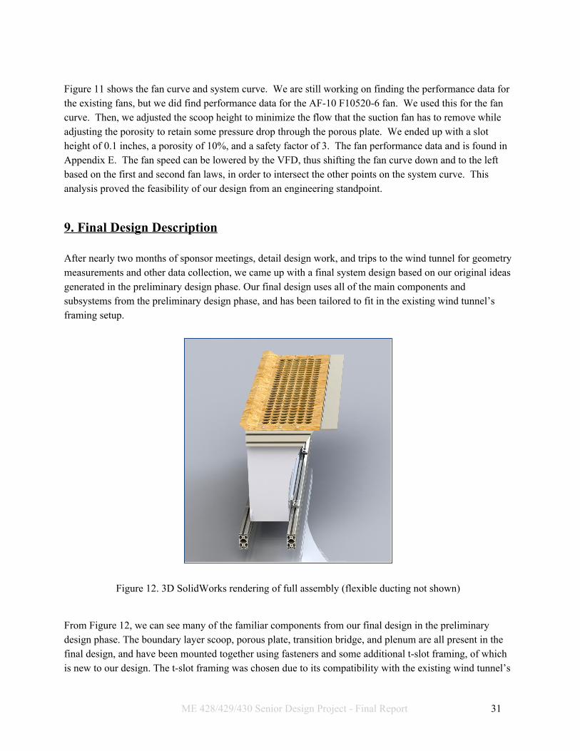
Figure 11 shows the fan curve and system curve. We are still working on finding the performance data for the existing fans, but we did find performance data for the AF-10 F10520-6 fan. We used this for the fan curve. Then, we adjusted the scoop height to minimize the flow that the suction fan has to remove while adjusting the porosity to retain some pressure drop through the porous plate. We ended up with a slot height of 0.1 inches, a porosity of 10%, and a safety factor of 3. The fan performance data and is found in Appendix E. The fan speed can be lowered by the VFD, thus shifting the fan curve down and to the left based on the first and second fan laws, in order to intersect the other points on the system curve. This analysis proved the feasibility of our design from an engineering standpoint.
9. Final Design Description After nearly two months of sponsor meetings, detail design work, and trips to the wind tunnel for geometry measurements and other data collection, we came up with a final system design based on our original ideas generated in the preliminary design phase. Our final design uses all of the main components and subsystems from the preliminary design phase, and has been tailored to fit in the existing wind tunnel’s framing setup.
Figure 12. 3D SolidWorks rendering of full assembly (flexible ducting not shown)
From Figure 12, we can see many of the familiar components from our final design in the preliminary design phase. The boundary layer scoop, porous plate, transition bridge, and plenum are all present in the final design, and have been mounted together using fasteners and some additional t-slot framing, of which is new to our design. The t-slot framing was chosen due to its compatibility with the existing wind tunnel’s
ME 428/429/430 Senior Design Project - Final Report 31

understructure, which is built almost entirely out of t-slot framing (with the exception of the inlet reduction and the rear diffuser).
For engineering purposes, the final design was broken up into various subsystems that serve an individual purpose for the operation of the device. These subsystems are presented in the following list:
● Ducting subassembly: The ducting subassembly provides the proper routing for the boundary layer air over the porous plate to be removed out of the tunnel’s test section. It consists of the plenum and flexible HVAC ducting that connects directly to the suction fans in the fan subassembly.
● ● Framing subassembly: The framing subassembly consists of the aluminum t-slot framing that
allows us to mount our system directly to the interior frame of the wind tunnel. This subsystem also includes all of the fasteners needed to connect the various t-slot extrusions together, as well as the mounting tabs and brackets needed to secure the plenum to the t-slot framing.
● ● Lid subassembly: The lid subassembly consists of the solid scoop, transition bridge, and the
porous plate that were all discussed in the preliminary design phase. For our final design, we merged the three components into one removable subassembly that allows for both the device to be easily manufactured and the wind tunnel to quickly switch between air vehicle and ground vehicle testing.
● ● Fan subassembly: The fan subassembly consists of the suction fans used to power the device.
These fans will connect directly to the tunnel’s VFD, of which is still under construction at this point in time. We already own the suction fans that will be used in the device, and multiple different fans are present in the tunnel for testing and design verification once the device has been constructed.
ME 428/429/430 Senior Design Project - Final Report 32

9.1 Ducting Subassembly Our ducting will consist of three main parts: rectangular stainless steel ducting, flexible ducting, and foam inserts.
Figure 13. SolidWorks rendering of plenum
The rectangular 16 gauge stainless steel ducting is shown in Figure 13. It will be attached to the frame and the top of it will be a ¼ inch lower than the bottom of the wind tunnel. This leaves enough room above it for a wood board to be placed on top of it, flush with the bottom of the wind tunnel, for when suction removal is not needed. The plenum has been designed to use a rectangular cross section for ease of manufacturing. At the inlet, the cross-section will be 12 inches by 43 inches. At the bottom, it will be 7 inches by 43 inches. The ducting will curve from the top to the bottom on the side closest to the rolling road so that it hugs the road. The ducting will drop straight down on the other side in order to leave enough room for the redirected flow to exit. The rectangular ducting will be 24 inches tall. Centered at the bottom of it, there will be a 6 inch diameter circular outlet that connects to the flexible aluminum tubing.
ME 428/429/430 Senior Design Project - Final Report 33

Figure 14. Picture of flexible ducting
The 6 inch flexible ducting is shown in Figure 14. It will connect to the outlet of the plenum and directly to the fan.
Figure 15. SolidWorks rendering of foam inserts inside of plenum
Figure 15 shows the foam inserts on the inside of the rectangular ducting. We will cut the foam and paint its surface so that it transitions the rectangular inlet to the circular outlet smoothly.
ME 428/429/430 Senior Design Project - Final Report 34

Analysis An important aspect of the ducting that needs to be analyzed is the pressure drop through it. The purpose of the foam is to reduce the amount of minor losses due to abrupt changes in geometry. Thus, most of the pressure drop will be from friction, and therefore very low overall. As Appendix D shows, if the ducting removes 820 CFM of air, the pressure drop will be .8 inches w.g, which, as we will show in the context of our fan subassembly, is sufficiently small. At first, we considered having the ducting be 18 inches tall. However, after investigating how much increasing the height to 24 inches affected the minor loss coefficient, we found that the minor loss coefficient was 6.7% more for the 18 inch height. This is due to the change in angle between the sloped plenum inserts as a result of the added height. As the angle is smaller at 24 inches, the amount of head loss created in the contraction becomes significantly smaller. Since we have 50 inches of room, we decided to go with the 24 inch height, resulting in an overall plenum height of 30 inches with the flexible tubing connection.
9.2 Framing Subassembly In order to support the entirety of our boundary layer suction system, we have elected to construct a frame out of t-slotted aluminum. The final layout of the framing is shown in Figure 16.
Figure 16. Solidworks rendering of the extruded aluminum framing, including lid mounts.
As previously mentioned, using slotted aluminum framing provides us the ability to easily integrate into the existing wind tunnel structure, and also allows for streamlined assembly. The slotted framing is a six piece structure, with two tunnel width pieces as well as two lid-mounts and two cross pieces used to
ME 428/429/430 Senior Design Project - Final Report 35

support the plenum. Furthermore, given the nature of t-slotted framing, putting the structure together will require only included bolt-on hardware, as opposed to additional manufacturing techniques such welding. This framing assembly mounts directly to the 3” by 6” t-slotted extrusions that make up the supports to the wind tunnel test section using linear bearings. These bearings have the ability to be locked in place but when necessary, may be moved vertically to adjust the height of the scoop for different boundary layers as need be. Additionally, the mobility of the system allows for easier access and maintenance of the plenum, and it can be easily removed from the tunnel when needed. Initially, we had planned to create a separate t-slot frame that would rest on casters and “lift” into the wind tunnel by sliding the plenum vertically within the extrusion slots. This rolling frame would also incorporate the fan(s) on a lower platform to allow for a separate, mobile setup. However, given the spatial requirements of the wind tunnel, and a desire to have a fully integrated suction system, we opted for the bearing-mounted support frame.
9.3 Lid Subassembly The lid subassembly combines some of the main components of the original concept from the preliminary design phase into one single subassembly. The job of the lid subassembly is to integrate the two main methods of boundary layer removal using both the solid scoop and the porous plate. Additionally, the lid subassembly contains the transition bridge, of which provides a smooth surface for the remaining flow downstream of the porous plate to transition smoothly onto the rolling road. Essentially, the lid subassembly provides the interface for boundary layer removal to occur, along with the help of the suction fans and ducting.
Figure 17. 3D SolidWorks rendering of the complete lid subassembly
ME 428/429/430 Senior Design Project - Final Report 36

The idea to blend the scoop, porous plate, and transition bridge evolved during a meeting with our sponsor during the CDR design phase. While at the wind tunnel, Dr. Doig noted that our device would need to be easily shelved if the wind tunnel was used to test air vehicles instead of ground vehicles. While the ducting and framing are securely positioned in the limited space underneath the wind tunnel, the porous plate/scoop/transition bridge actually occupied a space that was already being covered by a wood panel that was used for airfoil testing in the tunnel for one of the AERO classes on campus. One of Dr. Doig’s assistants meeting with us informed us that if we could make the lid assembly removable for non-ground vehicle testing, then we could keep the plenum and other parts in place and simply change the lids out, saving us plenty of time between tests and allowing the more rigid parts to maintain their current positions underneath the tunnel’s framing.
Figure 18. 3D SolidWorks Rendering of the lid subassembly in position inside the tunnel
The lid subassembly is designed to fit closely inside the tunnel while taking up as little extra space as possible. The porous plate is the central component of the subsystem, and it houses both the solid scoop in the front and the transition bridge in the rear. The transition bridge is still mounted using a piano hinge, which allows the transition bridge to change orientation depending on the height of the tunnel. The transition bridge is designed to rest lightly on the surface of the rolling road, allowing for air moving over the porous plate to transition smoothly between the lid and the rolling road without any further aerodynamic disturbances. The solid scoop is mounted directly to the front of the porous plate, and directs any incoming flow within the boundary layer in the tunnel reduction out through a small gap in the floor of the tunnel. Given that previous tests from other experiments have shown a boundary layer of slightly more than an inch tall in the tunnel without our device, the scoop should remove enough of the boundary layer in order for the suction fans to remove the rest before the flow reaches the rolling road.
ME 428/429/430 Senior Design Project - Final Report 37
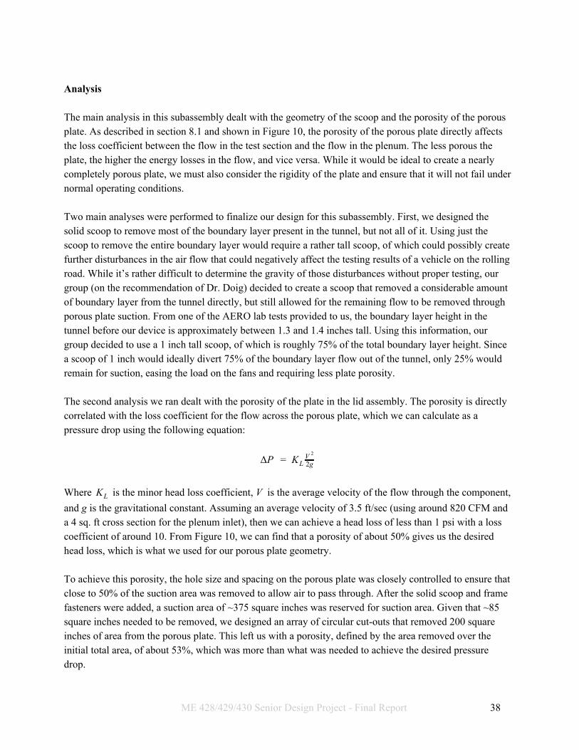
Analysis The main analysis in this subassembly dealt with the geometry of the scoop and the porosity of the porous plate. As described in section 8.1 and shown in Figure 10, the porosity of the porous plate directly affects the loss coefficient between the flow in the test section and the flow in the plenum. The less porous the plate, the higher the energy losses in the flow, and vice versa. While it would be ideal to create a nearly completely porous plate, we must also consider the rigidity of the plate and ensure that it will not fail under normal operating conditions. Two main analyses were performed to finalize our design for this subassembly. First, we designed the solid scoop to remove most of the boundary layer present in the tunnel, but not all of it. Using just the scoop to remove the entire boundary layer would require a rather tall scoop, of which could possibly create further disturbances in the air flow that could negatively affect the testing results of a vehicle on the rolling road. While it’s rather difficult to determine the gravity of those disturbances without proper testing, our group (on the recommendation of Dr. Doig) decided to create a scoop that removed a considerable amount of boundary layer from the tunnel directly, but still allowed for the remaining flow to be removed through porous plate suction. From one of the AERO lab tests provided to us, the boundary layer height in the tunnel before our device is approximately between 1.3 and 1.4 inches tall. Using this information, our group decided to use a 1 inch tall scoop, of which is roughly 75% of the total boundary layer height. Since a scoop of 1 inch would ideally divert 75% of the boundary layer flow out of the tunnel, only 25% would remain for suction, easing the load on the fans and requiring less plate porosity. The second analysis we ran dealt with the porosity of the plate in the lid assembly. The porosity is directly correlated with the loss coefficient for the flow across the porous plate, which we can calculate as a pressure drop using the following equation:
P KΔ = L 2gV 2
Where is the minor head loss coefficient, V is the average velocity of the flow through the component,KL and g is the gravitational constant. Assuming an average velocity of 3.5 ft/sec (using around 820 CFM and a 4 sq. ft cross section for the plenum inlet), then we can achieve a head loss of less than 1 psi with a loss coefficient of around 10. From Figure 10, we can find that a porosity of about 50% gives us the desired head loss, which is what we used for our porous plate geometry. To achieve this porosity, the hole size and spacing on the porous plate was closely controlled to ensure that close to 50% of the suction area was removed to allow air to pass through. After the solid scoop and frame fasteners were added, a suction area of ~375 square inches was reserved for suction area. Given that ~85 square inches needed to be removed, we designed an array of circular cut-outs that removed 200 square inches of area from the porous plate. This left us with a porosity, defined by the area removed over the initial total area, of about 53%, which was more than what was needed to achieve the desired pressure drop.
ME 428/429/430 Senior Design Project - Final Report 38

9.4 Fan Subassembly
Figure 19. AF cast aluminum blower
Figure 19 shows the AF10 fan, of which was provided to use for use in our device. It has radially inclined blades and a 6 inch inlet. It is a 1.5 hp fan and is designed to run at 3600 rpm. Since we are using semi rigid ducting, this gives us flexibility when it comes to where we will mount the fan. Once it is mounted, it will need to be hooked up to a VFD. The VFD will not be set up by the time our project concludes, so for our testing, we will use other fans in parallel. There are 4 other fans, totaling 3 hp, that are already connected to a controller box and can be used for testing. There is also a 2 hp mini wind tunnel that can be used. Analysis As mentioned already, previous tests show that the boundary layer height is 1.325 inches, and that for a scoop height of 1 inch, this leaves 820 CFM to be removed by the fan through the ducting.
ME 428/429/430 Senior Design Project - Final Report 39
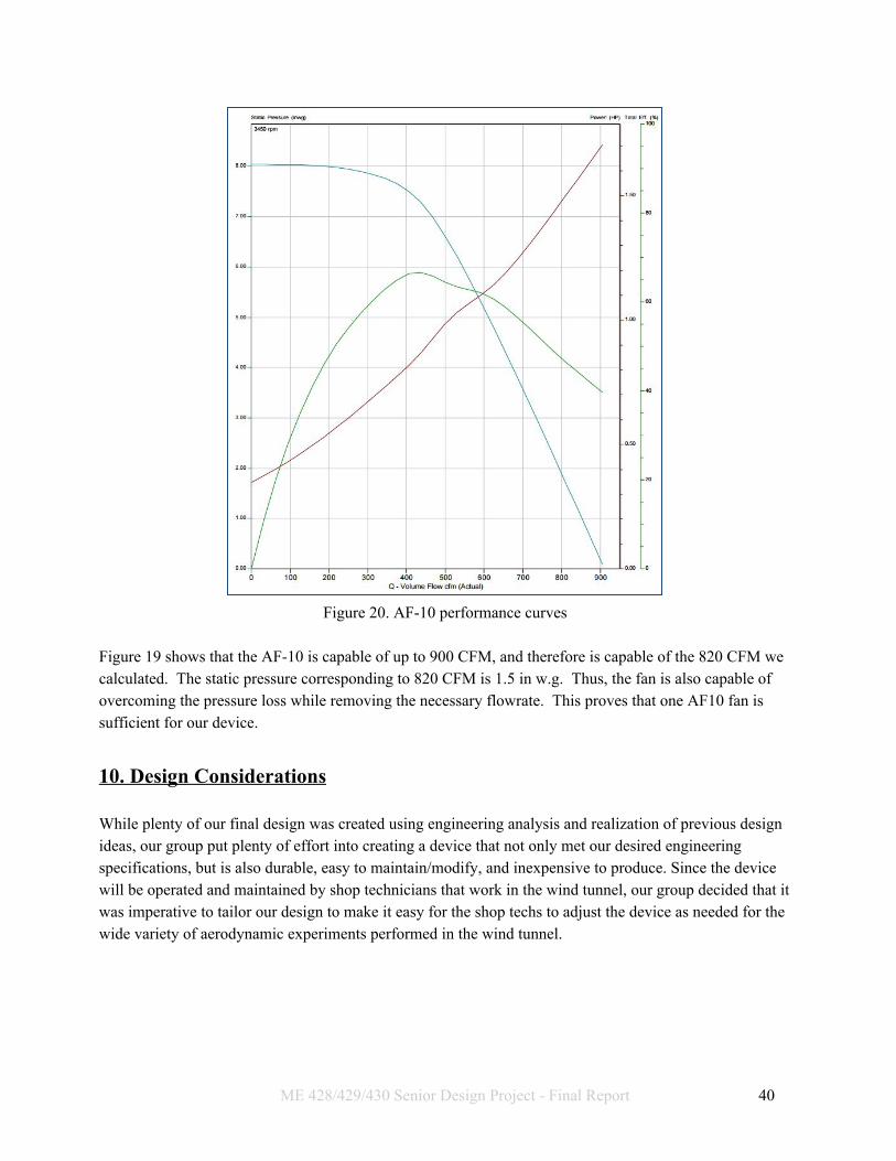
Figure 20. AF-10 performance curves
Figure 19 shows that the AF-10 is capable of up to 900 CFM, and therefore is capable of the 820 CFM we calculated. The static pressure corresponding to 820 CFM is 1.5 in w.g. Thus, the fan is also capable of overcoming the pressure loss while removing the necessary flowrate. This proves that one AF10 fan is sufficient for our device. 10. Design Considerations While plenty of our final design was created using engineering analysis and realization of previous design ideas, our group put plenty of effort into creating a device that not only met our desired engineering specifications, but is also durable, easy to maintain/modify, and inexpensive to produce. Since the device will be operated and maintained by shop technicians that work in the wind tunnel, our group decided that it was imperative to tailor our design to make it easy for the shop techs to adjust the device as needed for the wide variety of aerodynamic experiments performed in the wind tunnel.
ME 428/429/430 Senior Design Project - Final Report 40

10.1 Failure Modes & Effects Analysis Appendix D is our Design Failure Modes and Effects Analysis, showcasing the potential errors in our system and the overall damage that each poses to the functionality and safety of our prototype. During the design process, we used these potential failure modes to guide the progression of our design approach until we reached our final design. The attached spreadsheet showcases the various failure modes and associated mechanisms we could possibly face during operation of the device, and how we shaped our design approach in response. Each of the failure modes and causes shown in the FMEA are weighted to determine which of the problems that we have potential to face are worse than others. The factors that play into this include the severity of the event in question, as well as how often we believe that it may occur. Combined, this gave us the criticality of each event, with the more drastic requiring extra precautions to prevent them from happening. As an example, we opted for inserts to our plenum in order to counteract the pressure losses as a result of a sharp contraction, which would have ultimately decreased fan performance and may have led to the failure of our system. The solutions devised for each of these more severe situations guided us through the design process and allowed us to preemptively protect our final design. Overall, our suction system has relatively minor failure modes, with the most extreme case being an overworked fan that has potential to catch fire at the lowest probability of occurrence. Much of the time, a failure in our system was predicted to result in short periods of downtime in order for them to be fixed, or a solution is thought of that could prevent these errors in the future. After determining these failure modes and proposing solutions for the worst, the process of using our best judgement to decide on severity and probability was repeated. With these, the criticality always dropped below that of the previous design, as expected, and was often below a criticality of 10, which is generally considered minor. 10.2 Maintenance Plan The frame and plenum are meant to be semi-permanent structures and so maintenance will generally not be done on them, though it can be. If, for example, the foam shifts to the block the plenum outlet, the ducting can be slid down and opened. Most of the maintenance, though, will be for the lid. The lid is removable and will be placed on top of the plenum whenever the rolling road is in use. The scoop and porous plate are two parts of the lid that can be easily manufactured and remade. If the scoop causes separation, it may need to be cut to a different shape. If the porosity of the plate is not giving the necessary pressure drop, a plate with a different porosity can be cut from another sheet of wood. These two parts will not need to be replaced due to wear, but only to improve functionality. The transition bridge, on the other hand, will wear from contact with the rolling road. Thus, maintenance on the lid will involve periodically replacing the transition bridge. All maintenance for the fan will be done by professional electricians. The flexible ducting that connects to the fan may eventually break or rupture. If this happens it will be patched, if possible, or replaced. It is easy to replace since it is a stock part from Home Depot.
ME 428/429/430 Senior Design Project - Final Report 41

10.3 Projected Cost Estimates Arguably the most important aspect of our design is the total cost for all parts, shipping, and manufacturing. In the preliminary design phase, we estimated a total cost of around $450 for our entire project, of which had yet to go through the detail design phase and be subjected to a more thorough cost breakdown. As our group worked through various iterations of what would end up being our final design for this report, we made significant efforts in keeping costs as low as possible for the entire assembly. These efforts included proper material selection, consulting multiple vendors for pricing quotes, and factoring shipping and handling costs into whatever parts we needed to complete the design. In the end, we estimated that the entire device will cost around $650, including all applicable tax and shipping. A summary of each subsystem’s pricing information is presented below:
● Ducting Subassembly (200- level) ○ Total cost: $165.30 ○ Most expensive item: Plenum ($10.00 manufacturing + $120.00 materials cost)
● Framing Subassembly (300- level)
○ Total cost: $401.44 ○ Most expensive item: T-slot extrusions ($161.38)
● Lid Subassembly (400- level)
○ Total cost: $76.41 ○ Most expensive item: Porous plate ($14.50)
● Fan Subassembly (500- level)
○ Total cost: $0.00 (all parts currently in possession)
11. Manufacturing At the conclusion of the critical design phase of our project, we began ordering our parts from the vendors listed in the Bill of Materials. This included ordering parts using our CPConnect account through the Aerospace Engineering department, manually picking up materials from hardware stores, and receiving pre-made parts supplied by third-party manufacturing sources. Overall, this process took nearly 2 months to complete, as our team ran into many unforeseen issues with the manufacturing and assembly of multiple individual components, as well as the entire system as a whole. However, by the time of the project’s conclusion, our team was able to provide a fully-assembled device that met all of the original sizing & material specifications laid out in the critical design report.
ME 428/429/430 Senior Design Project - Final Report 42

11.1 Plenum Construction The first major part our team received was the plenum, which was the HVAC-style ducting detailed previously in section 9.1. The plenum was provided to us by Paladin Sheet Metal, a vendor located in Paso Robles, CA. We originally reached out to Paladin during the critical design phase in order to get an opinion on our original plenum designs to see if they could be easily manufactured to our specifications. Not only did Paladin offer useful advice on how to implement the plenum, but they also offered to manufacture the part for us at a reduced cost. After the critical design phase was complete, we sent our plenum part drawing over to Paladin for a cost estimate for manufacturing. To our aid, Paladin furthered their generosity and offered to make the entire part for us with no charges for both materials and manual labor. This was an incredible offer for our team, and helped severely trim our project’s total cost. Paladin provided us with the plenum before the end of ME 429 in March 2017, allowing us to begin the manufacturing processes earlier than expected. The plenum was crafted from 16 gauge sheet metal, of which was spare material that Paladin had at their Paso Robles shop location. Each sheet metal part was carefully crimped and folded together at the edges to form the ducting. The open edges of each part were folded and crimped to ensure that all sides of the plenum stayed rigid under loading, which helped the plenum maintain the complex shape we designed to fit within the wind tunnel’s geometry constraints. In order to hold the curved back of the plenum straight, we were also provided with a small brace that fit within a tab that forced the plenum to be flat on top. Without this brace, the curved back would weaken and bend to an undesired shape, of which is shown in Figure 20.
Figure 20. Plenum warping without addition of structural brace
When the plenum was first received by our group, we underestimated the effect that this plenum warping action could have on the final product. With the brace installed, the plenum was perfectly square on top,
ME 428/429/430 Senior Design Project - Final Report 43

and the lid could be mounted to the plenum framing without any problems. However, the brace did have a significant amount of material sticking up through the space that was to be occupied by the porous plate, and thus needed to be modified in order to allow for complete assembly. Our first action was to use the sheet metal forming tools in the Aero Hangar Machine Shop to bend and modify the brace in order to sit entirely underneath the top of the plenum, out of the way of any hardware in the lid subassembly. We were able to modify the brace to fit this criteria, but the geometry changes caused the brace to weaken and fail to hold the back of the plenum straight. This caused the curved back to slightly warp upwards into the lid area, causing the lid to have a noticeable ridge near the end of the porous plate.
Figure 21. Side profile of plenum showing the raised back edge
After the brace had already been modified in the shop, our group decided to come up with an alternate method for straightening the back edge of the plenum. We again consulted with Paladin sheet metal, who suggested that we make a rigid, fastener-mounted brace that mounts to the back of the plenum. Since we designed for a gap between the plenum back and the rolling road in the wind tunnel, we decided to make an external brace in order to prevent any flow blockage inside the plenum. This brace was made from a 1” thick block of plywood, and was mounted using 7 fasteners drilled through clearance holes in the back of the plenum. The fasteners held the block of wood firm against the back of the plenum, and bore most of the load that was causing the plenum back to deform in the first place. This new wooden brace did deform slightly, but the deflection when completely installed was roughly the same as the original brace that Paladin had created when we first received the plenum. This brace forced the top of the plenum to lie flat for the installation of the lid, but still fit within the geometric constraints that we first identified at the beginning of the project. Once the bracing issue was resolved, we began creating all of the mounting holes in the plenum for the framing to attach to. Given that we could not disassemble the plenum in any way, we had to come up with some alternative methods for creating these clearance holes. Our solution was to tap each individual hole with hand drill, place leftover wood blocks inside the plenum for support, and use the specified actual drill size to manually cut each hole around the plenum. This process was long and potentially risky, but we were able to create all 16 holes around the plenum called out in the drawing for P/N 201 in Appendix E. The holes were not controlled by any special size tolerances, so in every case the holes were drilled slightly larger than required by the drawing in order to facilitate assembly later on in the manufacturing
ME 428/429/430 Senior Design Project - Final Report 44

process. After the holes were drilled manually, both sides of the plenum were sanded using a dremel and inspected to make sure that no sharp edges or scrap metal remained. Before the plenum was considered complete, we attempted to mount all of the framing around the plenum to ensure that everything fit without any problems. In doing so, we ran into three significant issues. First, the side flaps that were installed by Paladin for structural rigidity were interfering with the t-slot extrusions that mounted to the sides of the plenum. These flaps were covering up the slotted section of the extrusions, and were blocking any fasteners needed to mount the lid to the top of the plenum. This issue was easily resolved by using high-strength tin snips, special scissors for cutting metal, to carefully trim a small amount of the flaps away in order to allow for just enough space for the mounting fasteners to fit into their backs within the extrusions. Plenty of spare material was left on the flaps to maintain the original structural strength, as the flaps held the sheet metal on the sides of the plenum taut. Once this was complete, the side extrusions fit as designed, and they were firmly mounted to the plenum using the specified fasteners. Next, we realized that the plenum had difficulties mounting to the bottom framing due to discrepancies between our part drawing and the physical plenum. When the plenum was made by Paladin, the floor of the plenum was used to create rather large crimps that held all 5 panels (consisting of 4 sides + the floor sheet) firmly together without having to use any epoxy or welding. These crimps raised the floor of the plenum slightly, and made it difficult to mount to the framing due to misalignment. In order to fix this problem, we performed two separate actions. First, we extended the mounting holes in the plenum by using a dremel to turn the holes into small vertical slots. After that, we performed the same process on the mounting brackets, this time using a vertical end mill since the brackets were made of much thicker material. In both cases, the 5/16” mounting holes were extended roughly ¼” upwards to allow for the fasteners to fit without any interference. With the new mounting slots instead of the original holes, we were able to create just enough clearance for the fasteners to fit and hold the plenum firm against the t-slotted bottom framing. Lastly, we ran into difficulties in mounting the lid subassembly to the top of the plenum again due to interference between the plenum front panel flap and the mounting bolts that held the solid scoop to the top of the porous plate. Details for the solid scoop mounting will be discussed in the following section, but the plenum front panel flap needed to be modified to accommodate these mounting bolts. Our solution was to cut small notches in the front panel flap using the same tin snips as before, and then removing the excess material and sanding the edges to remove any potential sharp corners. This was a rather simple operation, but since the front panel flap had to have significant material removed, the front panel lost most of its original rigidity. We were aware of this unintended side effect before the operation, and chose to proceed since the front panel bears no significant loading and is still strong enough to hold shape during operation. Once this process was complete, the plenum was completely manufactured, and work began to focus on other subassemblies.
ME 428/429/430 Senior Design Project - Final Report 45

11.2 Lid Construction The lid’s three components--the porous plate, suction scoop, and transition bridge--were constructed in order to fit together as a whole, and to attach to the plenum. The transition bridge required minimal manufacturing. Holes were drilled into it and the piano hinge was screwed to it through these holes. Rather than machine the end of the transition bridge to fit with the curve of the rolling road, we decided it would be safer to have the rolling road wear down the transition bridge. Once the rolling road is operational, it will quickly rub down the transition bridge to a nice fit without the rolling road belt wearing out. This prevents the possibility of machining too much material off part of the transition bridge surface, thus necessitating the replacement of the transition bridge.
Figure 22. Top view of porous plate and transition bridge
The porous plate was redesigned to have slots instead of holes, as shown in Figure 22. The downside of this is that the MDF board loses some of its strength when the material that would have existed between holes in a single row is removed. This causes the board to sag slightly. However, the upside is that the slots are perpendicular to the flow, and thus will remove air more evenly. Since the removal of air is our ultimate goal, we decided that we should go with slots instead of holes. Holes were drilled in the porous plate as well. The piano hinge was screwed onto the porous plate as well. The side holes allow the porous plate to be screwed onto the top of plenum, attaching to the T-Slot framing on the sides. As was mentioned in 11.1, some of the plenum had to be cut off with tin snips to avoid interference with the screws. There are also holes on the front for the scoop to attach to.
ME 428/429/430 Senior Design Project - Final Report 46

Figure 23. Side view of scoop
The scoop is shown in Figure 23. It was bent from sheet metal using a sheet metal bender and then hammered into place. As you can see, holes were drilled into the bottom of it and screws were pushed through the holes from the inside, which was accessible by bending the inside back open. As mentioned in the 11.1, these screws also interfered with the plenum, and tin snips had to be used to remove this interference. Finally, the scoop was welded together to prevent it from bending once in the wind tunnel. 11.3 Device Installation Process Once the lid and ducting subassemblies were fully manufactured, our group assembled the framing by using the t-slotted extrusions and hardware purchased from T-Slots. This was a fast and rather simple process, and formed a rigid base for our device once completed. The only manufacturing work for this subassembly was simply inserting the screw mounts into the designated slots, and using the appropriate size allen wrenches to tighten the fasteners until they held each extrusion and bracket firmly in place. Once all of the subassemblies were complete, we moved everything into the wind tunnel (41-139) on campus for final device installation. As discussed in the critical design phase of this project, the framing subassembly was purposefully designed to easily mesh with the existing t-slotted framing that forms the test section of the wind tunnel. In specific, our device’s framing mounts directly to linear bearings that are attached to the sides of the tunnel’s support columns. These linear bearings are designed to allow our device to easily slide up & down on the tunnel’s framing, allowing for the device to be quickly stowed when not in use. In order to mount our device’s framing to the linear bearings, we had to carefully place the framing under the wind tunnel and make slight adjustments to the position of each extrusion to allow the framing to align properly with the bearings. Once the framing was secured and positioned with the bearings, we secured the framing using leftover fasteners in the wind tunnel’s toolbox. A completed framing system is shown in Figure 24.
ME 428/429/430 Senior Design Project - Final Report 47

Figure 24. Fully-assembled framing subsystem
One the framing was fully installed in the wind tunnel, we began mounting the rest of the system into the tunnel. We started with the plenum, as the plenum sits directly on the horizontal extrusions of the framing. We mounted the plenum by first removing the mounting tabs from the framing, fastening them to the plenum, and then fastening the plenum onto the framing using the same t-slots hardware as before. This was a simple task, and the plenum fit snugly against the rolling road even with the thicker brace on the back edge. Once this was complete, we slid the plenum down on the linear bearings in order to mount the lid to the plenum. As expected, the lid fit perfectly, and once the plenum was raised back to the rolling road’s height, the transition bridge laid flat on the road as designed. To finish the assembly, the flexible tubing was placed around the outlet of the plenum, and fastened into place using the worm gear clamp that came with the tubing.
ME 428/429/430 Senior Design Project - Final Report 48

Figure 25. Fully assembled device flush against rolling road. Note that the rolling road is not raised to the
height of the tunnel floor 11.4 Final Cost Analysis Based on the original cost estimation presented during the critical design phase, our final fully manufactured prototype ended up costing far less than expected. From Section 10.3, we originally expected our device to cost upwards of $650, including parts + tax and shipping, manufacturing costs, material costs, and more. However, we were able to create our final prototype for nearly a third of this estimated cost by contracting through vendors that gave us steep discounts for the most expensive parts. As previously mentioned, Paladin Sheet Metal gave us the entire plenum for free, which knocked $120 off of our estimated cost right off the bat. In addition, T-Slots offered us a 50% discount on all extrusions and hardware in addition to free shipping, which would have been expensive in itself given the size and weight of the extrusions. Overall, we spent $236.65, including all applicable taxes. The entire budget used is presented in Appendix D, which contains the Bill of Materials. A summary of each subsystem’s final pricing information is presented below:
● Ducting Subassembly (200- level) ○ Total cost: $19.51 ○ Most expensive item: Flexible ducting ($15.49)
● Framing Subassembly (300- level)
○ Total cost: $154.39 ○ Most expensive item: T-slot extrusions ($50.01)
ME 428/429/430 Senior Design Project - Final Report 49

● Lid Subassembly (400- level) ○ Total cost: $62.75 ○ Most expensive item: Transition Bridge ($14.16)
● Fan Subassembly (500- level)
○ Total cost: $0.00 (all parts currently in possession) 12. Testing & Design Verification Plan As a last step to this process, our design must be tested to ensure ideal performance and safety for use in the Aerospace Engineering Department’s Wind Tunnel. The performance targets which we are aiming to achieve with this project are highlighted in Section 3, Table 2 which shows the engineering specifications. Through our design process, we placed emphasis on these goals with the hope that our analysis and design considerations were correct and will allow us to meet these standards. Further, we hope that through testing, any individual flaws in the boundary layer suction device can be identified and remedied. Of the results obtained from testing, the most important pertain to proving that the boundary layer can in fact be safely removed from the rolling road using our system.. 12.1 Testing Procedures Prior to testing (or using) the boundary layer suction device in the wind tunnel, it must be properly set up for operation. After the T-Slot plenum support framing has been affixed to the wind tunnel’s frame using the linear bearings, the plenum should be lowered in though the wind tunnel test section and rested on top. Once centered in the wind tunnel, the plenum may be affixed to the brackets on the framing using the eight 5/16” screws and four threaded backing plates that they attach to. Then, the lid containing the scoop, porous plate, and transition bridge may be connected to the T-Slots that sit on the outside of the plenum. With these in place, the system should be moved vertically until the top of the porous plate is in line with the rolling road, and the transition bridge is resting horizontally on top. Below the plenum and framing assembly, the flexible aluminum ducting must be connected to the 6” flange of the plenum using a worm gear clamp, as well as the suction fans. In order to prove that the system works as expected, we need to set up a control with which to compare our final results. To do so, we have decided to set up a “before-and-after” test to show that the boundary layer is actually being removed. The before part will take place ahead of our system and at the end of the wind tunnel contraction section. A pitot-static boundary layer probe will be placed in the middle of the tunnels’ lateral plane at floor level, marking the start point. With the wind tunnel and data acquisition program running, the operator will take a sufficient number (20+) of incremental measurements until the readings reach 99% of the free stream velocity in order to map the boundary layer. From previous tests, this boundary layer should be approximately 1.3 inches high. The same procedure should be performed directly after the scoop as well as after the porous plate where the transition bridge meets the rolling road. This gives us a picture of the airflow across our system, and where there are discrepancies in the ability to
ME 428/429/430 Senior Design Project - Final Report 50

remove the boundary layer. For further, more accurate representation, this process should be performed across different lateral distances and air speeds. For qualitative justification of our project, a fog machine test will be performed to visually inspect the flow and identify any unwanted aerodynamic disturbances. In order to complete this test, the individual running the test shall turn on the fan first before adding fog into the stream. Once the fan has begun to spin up, they may place the fog machine near the mouth of the wind tunnel and turn it on. When the flow of fog through the test section becomes steady and fully-developed, begin to observe the behavior over the lid of our system and onto the rolling road. In order to gain a better visual of the potential turbulences, a strobe light should be used in order to do so. This will give a better idea of specific locations that may lead to faulty readings when the rolling road is put into use for measuring the aerodynamic performance of a given project that way they have the opportunity to be remedied. 12.2 Criteria for Completion With respect to the above testing procedures, there are a number of milestones that must be met in order to deem this project a success. Table 2 lists out the target engineering specifications which we are trying to meet. Before moving forward with any of the testing procedures, the most important thing is to ensure that the boundary layer system is level. This will ensure that there is no unwanted rubbing on the rolling road and that the scoop is at the right height, approximately 1” above the wind tunnel floor. When the actual testing results are obtained, the boundary layer should be reduced by 95% from the initial measurement location to the rolling road, from 1.3” to about 1/16 of an inch. Also, the design of the scoop should ideally remove 1” of the boundary layer before the air even reaches the plate. These results should be checked as well at the second probe location to prove that the scoop performs as expected. Finally, we designed the system to be as aerodynamic as possible. Therefore, there should be little to no vortices or turbulence visible as a result of our system. 12.3 Testing and Operational Safety Considerations
12.3.1 Objects Inserted into Airstream ● Objects such as the air scoop that are protruding into the air stream are subject to the
aerodynamic forces of the air passing over them. As such, they may come loose over time and pose a significant threat to the wind tunnel, as well as those operating it. When the boundary layer system is in use, ensure that:
○ All components associated with this device are firmly secured, such as the scoop and transition bridge to the lid, or the lid to the plenum.
○ All doors and access points on the wind tunnel are locked closed. ○ There are no individuals standing downstream of the test section to the wind
tunnel, primarily at the exhaust of the wind tunnel.
ME 428/429/430 Senior Design Project - Final Report 51

● If there is any doubt that an object has become loose, or looks as if it may become loose, shut down the fan immediately.
○ Once the fan has stopped moving, an operator may access and fix the part in question.
12.3.2 Strobe Light for Visual Testing
● Strobe lights are known to cause seizures in those who are vulnerable to epileptic attacks. Caution should be exercised when operating a strobe light to analyze disturbances in the fog stream, and any individuals who may be prone to a seizure should be removed from the room prior to beginning the test.
12.4 Current Testing Status Due to a number of unexpected obstacles in the manufacturing process, our timeline was shifted and minimal testing was able to be accomplished as a result. Further, as the wind tunnel is also used for academic instruction, we have had trouble finding a time that we could go in and run tests. This is mostly due to the fact that we would have to interfere with the components needed to run the lab procedures. At this current time, we only have the ability to test the scoop as well, which is only a small part of our project. Due to the fact that the VFD required to run our suction fans is not currently installed, we do not have the ability to test the porous plate’s effect on the boundary layer as it transitions to the rolling road. However, once the rolling road is moved into place (moved back and up to floor height) and the fans have the ability to be installed, testing should be a quick process before making the system operational.
ME 428/429/430 Senior Design Project - Final Report 52

Appendix A: Quality Function Deployment
ME 428/429/430 Senior Design Project - Final Report 53

Appendix B: Project Gantt Chart
ME 428/429/430 Senior Design Project - Final Report 54

Wind Tunnel B
oundary Layer Suction Device - B
ill of Materials
Assem
blyPart N
o.Item
Material
Qty.
SourceV
endor P/NB
ase Cost
Total Cost (w
ith Tax)O
rderedR
eceived100
Top Assem
bly---
1---
------
$236.65200
Plenum Sub-A
ssembly
---1
------
---$19.51
201Plenum
Steel1
Paladin Sheet Metal
---$0.00
$0.00Y
3/2/17202
Plenum Inserts
Polyurethane1
Hom
e Depot
203837080$5.00
----
--203
Flexible Ducting
Alum
inum1
Hom
e Depot
205046831$14.61
$15.49Y
3/8/17204
Flexible Ducting A
ttachment
Steel1
Hom
e Depot
203626509$2.31
$2.45Y
3/8/17300
Frame Sub-A
ssembly
---1
------
---$154.39
301Tunnel W
idth Extrusions (5 ft)A
nodized Alum
inum2
TSLOTS
650009$100.02
$50.01Y
3/6/17302
Plenum Support Extrusions (7")
Anodized A
luminum
2TSLO
TS650009
$17.62$8.81
Y3/6/17
303Lid Extrusions (1 ft)
Anodized A
luminum
2TSLO
TS650009
$34.64$17.32
Y3/6/17
304M
ounting TabsA
luminum
4TSLO
TS653137
$18.84$9.42
Y3/6/17
305D
ual Plate Fasteners (5/16"-18)Zinc-Plated Steel
40TSLO
TS651141
$63.20$31.60
Y3/6/17
306Single Plate Fasteners (1/4"-20)
Zinc-Plated Steel8
TSLOTS
651130$4.24
$2.12Y
3/6/17307
Quad Profile T-Slot B
racketA
luminum
8TSLO
TS653138
$56.24$28.12
Y3/6/17
308A
dditional 5/16-18 Nut
Zinc-Plated Steel6
TSLOTS
651132$13.98
$6.99Y
3/6/17400
Lid Sub-Assem
bly---
1---
------
$62.75401
Porous PlateM
DF
1H
ome D
epot813952014571
$7.49$7.94
Y3/8/17
402B
oundary Layer ScoopW
hitewood
1H
ome D
epot100038668
$2.07$10.07
Y4/16/17
403Scoop Fasteners (#8 x 0.75")
Zinc-Plated Steel7
Hom
e Depot
204275503$0.50 for 3
$2.50Y
4/16/17404
Porous Plate FastenersSteel
6M
cMaster-C
arr47065T327
$1.21 each$7.26
Y3/6/17
405Transition B
ridge Screws
Zinc-Plated Steel8
McM
aster-Carr
90273A148
$3.71 for box of 100$3.71
Y3/6/17
406Transition B
ridge Nuts
Zinc-Plated Steel8
McM
aster-Carr
90480A007
$1.24 for box of 100$1.24
Y3/6/17
407Transition B
ridgeA
BS Plastic
1M
cMaster-C
arr8712K
244$3.54 per foot
$14.16Y
3/6/17408
Piano Hinge M
ountSST 304
1M
cMaster-C
arr1658A
19$10.82
$10.82Y
3/6/17500
Fan Sub-Assem
bly---
1---
------
$0.00501
Suction FanN
/A1
Am
erican Fan Co.
---$0 (A
lready Ow
ned)$0.00
App
endi
x C
: Bill
of M
ater
ials
Appendix C: Bill of Materials
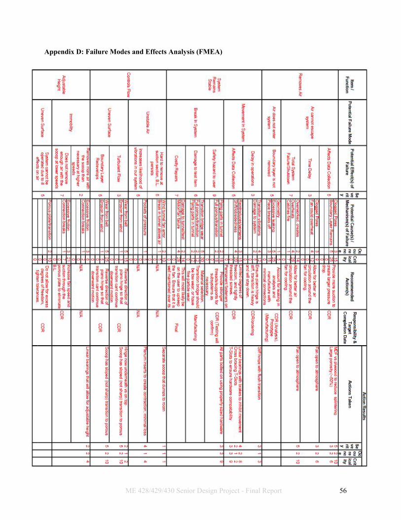
Appendix D: Failure Modes and Effects Analysis (FMEA)
ME 428/429/430 Senior Design Project - Final Report 56

Appendix E: Design Verification Plan
ME 428/429/430 Senior Design Project - Final Report 57

Appendix F: Part & Assembly Drawings Index of Part Drawings and Spec Sheets
1. Top Assembly a. 100 - Top Assembly
2. Ducting Subassembly a. 200 - Subassembly Drawing b. 201 - Plenum c. 202 - Plenum Inserts d. 203 - Spec Sheet for Flexible Ducting e. 204 - Spec Sheet for Flexible Ducting Attachment
3. Framing Subassembly a. 300 - Subassembly Drawing b. 301 - 6ft Extrusion c. 302/303 - 1ft Extrusion d. 304 - Single Mounting Bracket e. 305 - Dual Plate Fasteners f. 306 - Single Plate Fasteners (5/16”) g. 307 - Quad Mounting Bracket
4. Lid Subassembly a. 400 - Subassembly Drawing b. 401 - Porous Plate c. 402 - Solid Scoop d. 404 - T-Slot Spring Fasteners e. 405 - Transition Bridge Fasteners f. 406 - Transition Bridge Nuts g. 407 - Transition Bridge h. 408 - Piano Hinge Mount
5. Fan Subassembly a. 501 - Fan Spec Sheet
ME 428/429/430 Senior Design Project - Final Report 58

1
2
3
4
5
67
12
8
16 13
14
1510
11
9
SCA
LE 1:16
ITEM N
O.
PART N
UMBER
DESC
RIPTION
QTY.
1201
PLENUM
12
202PLEN
UM IN
SERTS1
3301
TUNN
EL WID
TH EXTEN
SION
S2
4302
PLENUM
SUPPORT EXTEN
SION
S2
5303
LID EXTRUSIO
NS
26
304M
OUN
TING
TABS
47
305D
UAL PLA
TE FASTEN
ERS40
8306
SING
LE PLATE FA
STENERS
89
307Q
UAD
PROFILE T-SLO
T BRAC
KET8
10401
PORO
US PLATE
111
402BO
UND
ARY LA
YER SCO
OP
112
404PO
ROUS PLA
TE FASTEN
ERS6
13405
TRAN
SITION
BRIDG
E SCREW
S8
14406
TRAN
SITION
BRIDG
E NUTS
815
407TRA
NSITIO
N BRID
GE
116
408PIA
NO
HING
E MO
UNT
1
AA
BB
4 4
3 3
2 2
1 1
TOP A
SSEMBLY
100SHEET 1 O
F 1
2/6/17D
AN
IEL G.
SCA
LE: 1:12W
EIGHT:
REVD
WG
. NO
.
B SIZE
TITLE:
NA
ME
DA
TE
CO
MM
ENTS:
Q.A
.
MFG
APPR.
ENG
APPR.
CHEC
KED
DRA
WN
SENIO
R PROJEC
T GRO
UP 44

21
ITEM N
O.
PART N
UMBER
DESC
RIPTION
QTY.
1201
Plenum1
2202
Plenum Inserts
1
AA
BB
4 4
3 3
2 2
1 1
DUC
TING
SUBA
SSEMBLY
DO
NO
T SCA
LE DRA
WIN
G
200SHEET 1 O
F 1
2/7/17RO
BBY C.
UNLESS O
THERWISE SPEC
IFIED:
SCA
LE: 1:16W
EIGHT:
REVD
WG
. NO
.
B SIZE
TITLE:
SENIO
R PR
OJEC
T GR
OU
P 44N
AM
ED
ATE
CO
MM
ENTS:
Q.A
.
MFG
APPR.
ENG
APPR.
CHEC
KED
DRA
WN
FINISH
MA
TERIAL
INTERPRET G
EOM
ETRICTO
LERAN
CIN
G PER:
DIM
ENSIO
NS A
RE IN IN
CHES
TOLERA
NC
ES:FRA
CTIO
NA
LA
NG
ULAR: M
AC
H BEN
D
TWO
PLAC
E DEC
IMA
L THREE PLA
CE D
ECIM
AL
APPLIC
ATIO
N
USED O
NN
EXT ASSY
PROPRIETA
RY AN
D CO
NFIDEN
TIAL
THE INFO
RMA
TION
CO
NTA
INED
IN THIS
DRA
WIN
G IS THE SO
LE PROPERTY O
F<IN
SERT CO
MPA
NY N
AM
E HERE>. AN
Y REPRO
DUC
TION
IN PA
RT OR A
S A W
HOLE
WITHO
UT THE WRITTEN
PERMISSIO
N O
F<IN
SERT CO
MPA
NY N
AM
E HERE> IS PRO
HIBITED.

4x 0.33
THRU ALL
24.00
36.00 8.50
1.50 1.50 43.00
21.50
12.00
7.00
6.00
3.50
R24.00
4x 0.33
THRU
6.00 1.50
5.00
A
0.063A
LL THICKN
ESSES
DETA
IL ASC
ALE 1 : 4
AA
BB
2 2
1 1Suction System
Plenum
DO
NO
T SCA
LE DRA
WIN
G
201SHEET 1 O
F 1
2/1/15Robby C
.
UNLESS O
THERWISE SPEC
IFIED:
SCA
LE: 1:12W
EIGHT:
REVD
WG
. NO
.
A SIZE
TITLE:
NA
ME
DA
TE
CO
MM
ENTS:
Q.A
.
MFG
APPR.
ENG
APPR.
CHEC
KED
DRA
WN
FINISH
MA
TERIAL
INTERPRET G
EOM
ETRICTO
LERAN
CIN
G PER:
DIM
ENSIO
NS A
RE IN IN
CHES
TOLERA
NC
ES:FRA
CTIO
NA
LA
NG
ULAR: M
AC
H BEN
D
TWO
PLAC
E DEC
IMA
L THREE PLA
CE D
ECIM
AL
0.005
APPLIC
ATIO
N
USED O
NN
EXT ASSY
PROPRIETA
RY AN
D CO
NFIDEN
TIAL
THE INFO
RMA
TION
CO
NTA
INED
IN THIS
DRA
WIN
G IS THE SO
LE PROPERTY O
F<IN
SERT CO
MPA
NY N
AM
E HERE>. AN
Y REPRO
DUC
TION
IN PA
RT OR A
S A W
HOLE
WITHO
UT THE WRITTEN
PERMISSIO
N O
F<IN
SERT CO
MPA
NY N
AM
E HERE> IS PRO
HIBITED.
Senior Project Group 44

23.94
19.44
48.15°
42.88 25.46
17.41
0.005A
A
R24.13
9.23
6.88
11.88 R2.94
AA
BB
2 2
1 1Plenum Inserts
DO
NO
T SCA
LE DRA
WIN
GSHEET 1 O
F 1
2/7/16Robby C
.
UNLESS O
THERWISE SPEC
IFIED:
SCA
LE: 1:12W
EIGHT:
REVD
WG
. NO
.
A SIZE
TITLE:
NA
ME
DA
TE
CO
MM
ENTS:
Q.A
.
MFG
APPR.
ENG
APPR.
CHEC
KED
DRA
WN
FINISH
MA
TERIAL
INTERPRET G
EOM
ETRICTO
LERAN
CIN
G PER:
DIM
ENSIO
NS A
RE IN IN
CHES
TOLERA
NC
ES:FRA
CTIO
NA
LA
NG
ULAR: M
AC
H BEN
D
TWO
PLAC
E DEC
IMA
L THREE PLA
CE D
ECIM
AL
0.005
APPLIC
ATIO
N
USED O
NN
EXT ASSY
PROPRIETA
RY AN
D CO
NFIDEN
TIAL
THE INFO
RMA
TION
CO
NTA
INED
IN THIS
DRA
WIN
G IS THE SO
LE PROPERTY O
F<IN
SERT CO
MPA
NY N
AM
E HERE>. AN
Y REPRO
DUC
TION
IN PA
RT OR A
S A W
HOLE
WITHO
UT THE WRITTEN
PERMISSIO
N O
F<IN
SERT CO
MPA
NY N
AM
E HERE> IS PRO
HIBITED.
Senior Project Group 44
202


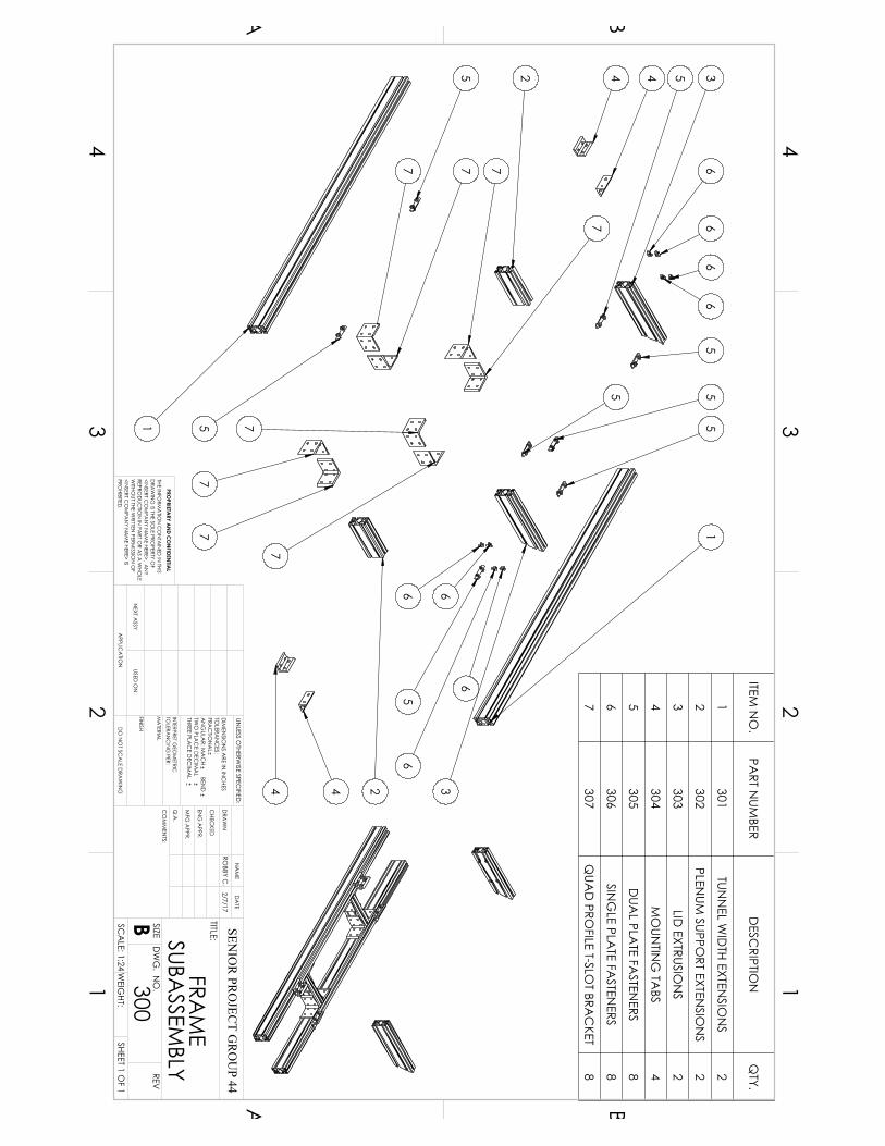
1
1
2
2 3
344
4 4
5
5
5 5
55
5
5
6
66 6
66
667 7 7
77
7
7
7
ITEM N
O.
PART N
UMBER
DESC
RIPTION
QTY.
1301
TUNN
EL WID
TH EXTEN
SION
S2
2302
PLENUM
SUPPORT EXTEN
SION
S2
3303
LID EXTRUSIO
NS
2
4304
MO
UNTIN
G TA
BS4
5305
DUA
L PLATE FA
STENERS
8
6306
SING
LE PLATE FA
STENERS
8
7307
QUA
D PRO
FILE T-SLOT BRA
CKET
8
AA
BB
4 4
3 3
2 2
1 1FRAM
E SUBA
SSEMBLY
DO
NO
T SCA
LE DRA
WIN
G
300SHEET 1 O
F 1
2/7/17RO
BBY C.
UNLESS O
THERWISE SPEC
IFIED:
SCA
LE: 1:24W
EIGHT:
REVD
WG
. NO
.
B SIZE
TITLE:
SENIO
R PR
OJEC
T GR
OU
P 44N
AM
ED
ATE
CO
MM
ENTS:
Q.A
.
MFG
APPR.
ENG
APPR.
CHEC
KED
DRA
WN
FINISH
MA
TERIAL
INTERPRET G
EOM
ETRICTO
LERAN
CIN
G PER:
DIM
ENSIO
NS A
RE IN IN
CHES
TOLERA
NC
ES:FRA
CTIO
NA
LA
NG
ULAR: M
AC
H BEN
D
TWO
PLAC
E DEC
IMA
L THREE PLA
CE D
ECIM
AL
APPLIC
ATIO
N
USED O
NN
EXT ASSY
PROPRIETA
RY AN
D CO
NFIDEN
TIAL
THE INFO
RMA
TION
CO
NTA
INED
IN THIS
DRA
WIN
G IS THE SO
LE PROPERTY O
F<IN
SERT CO
MPA
NY N
AM
E HERE>. AN
Y REPRO
DUC
TION
IN PA
RT OR A
S A W
HOLE
WITHO
UT THE WRITTEN
PERMISSIO
N O
F<IN
SERT CO
MPA
NY N
AM
E HERE> IS PRO
HIBITED.

NU
MBER
PART
Information in this draw
ing is provided for reference only.
http://ww
w.m
cmaster.com
1 1/2"
3"0.75"
1.5"
0.26"
0.81"0.32"
0.12"
6 ft.
47065T108Alum
inumT-Slotted Fram
ing©
2015 McM
aster-Carr S
upply Com
pany
P/N: 301
P/N 301

NU
MBER
PART
Information in this draw
ing is provided for reference only.
http://ww
w.m
cmaster.com
1 1/2"
3"0.75"
1.5"
0.26"
0.81"0.32"
0.12"
1 ft.
47065T108Alum
inumT-Slotted Fram
ing©
2015 McM
aster-Carr S
upply Com
pany
P/N: 302
P/N 302/3

NU
MBER
PART
Information in this draw
ing is provided for reference only.
http://ww
w.m
cmaster.com
1 1/2"
1 1/2"
1/4"
2 13/16"
3/4"
0.328"
1 1/2"
47065T23890° Bracket for
Aluminum
T-Slotted Framing
© 2015 M
cMaster-C
arr Supply C
ompany
P/N: 303
P/N 304

NU
MBER
PART
Information in this draw
ing is provided for reference only.
http://ww
w.m
cmaster.com
11/16"
21/32"
5/32"
5/16"-18 Thread
3/16" Hex 2 13/16"
5/8"
1 1/2"
47065T149End-Feed Fastener for
Aluminum
T-Slotted Framing
© 2015 M
cMaster-C
arr Supply C
ompany
P/N 305

NU
MBER
PART
Information in this draw
ing is provided for reference only.
http://ww
w.m
cmaster.com
1/2"
17/32"
3/32"
1/4"-20 Thread
5/32" Hex
1"
7/16"
47065T142End-Feed Fastener for
Aluminum
T-Slotted Framing
© 2015 M
cMaster-C
arr Supply C
ompany
P/N: 306
P/N 306

NU
MBER
PART
Information in this draw
ing is provided for reference only.
http://ww
w.m
cmaster.com
3"
3"
1/4"
2 13/16"
3/4"
0.328"
1 1/2"
1 1/2"
47065T254Extended 90° Bracket for
Aluminum
T-Slotted Framing
© 2015 M
cMaster-C
arr Supply C
ompany
P/N 307

12
34
567
ITEM N
O.
PART N
UMBER
DESC
RIPTION
QTY.
1401
PORO
US PLATE
12
402BO
UND
ARY LA
YER SCO
OP
13
403PO
ROUS PLA
TE FASTEN
ERS6
4404
TRAN
SITION
BRIDG
E SCREW
S8
5405
TRAN
SITION
BRIDG
E NUTS
86
406TRA
NSITIO
N BRID
GE
17
407PIA
NO
HING
E MO
UNT
1
AA
BB
4 4
3 3
2 2
1 1LID
SUBASSEM
BLY
DO
NO
T SCA
LE DRA
WIN
G
400SHEET 1 O
F 1
2/7/17RO
BBY C.
UNLESS O
THERWISE SPEC
IFIED:
SCA
LE: 1:16W
EIGHT:
REVD
WG
. NO
.
B SIZE
TITLE:
SENIO
R PR
OJEC
T GR
OU
P 44N
AM
ED
ATE
CO
MM
ENTS:
Q.A
.
MFG
APPR.
ENG
APPR.
CHEC
KED
DRA
WN
FINISH
MA
TERIAL
INTERPRET G
EOM
ETRICTO
LERAN
CIN
G PER:
DIM
ENSIO
NS A
RE IN IN
CHES
TOLERA
NC
ES:FRA
CTIO
NA
LA
NG
ULAR: M
AC
H BEN
D
TWO
PLAC
E DEC
IMA
L THREE PLA
CE D
ECIM
AL
APPLIC
ATIO
N
USED O
NN
EXT ASSY
PROPRIETA
RY AN
D CO
NFIDEN
TIAL
THE INFO
RMA
TION
CO
NTA
INED
IN THIS
DRA
WIN
G IS THE SO
LE PROPERTY O
F<IN
SERT CO
MPA
NY N
AM
E HERE>. AN
Y REPRO
DUC
TION
IN PA
RT OR A
S A W
HOLE
WITHO
UT THE WRITTEN
PERMISSIO
N O
F<IN
SERT CO
MPA
NY N
AM
E HERE> IS PRO
HIBITED.

13.00
46.00 0.75
6.00 10.00
14.00 10.00
8.00 5.00
5.00 5.00
5.00 5.00
5.00
45.25
4.00 2.25
10.00 7.00
3.50
4.00
7.00 10.00
1.25
1.50
1.50
7X0.13 TH
RU
6X0.25 TH
RU
NO
TE: PORO
US PLATE HA
S 162 HOLES
(6 HOLES TA
LL & 27 HO
LES WID
E) INPO
ROUS M
IDD
LE SECTIO
N. EA
CH
HOLE IS 1.25" IN
DIA
METER, A
ND
AD
JAC
ENT
HOLES A
RE SPAC
ED 1.50" A
PART IN
BOTH
HORIZO
NTA
L AN
D V
ERTICA
L DIREC
TION
S
PLATE IS M
AD
E FROM
0.25" THICK PLYW
OO
D
AA
BB
2 2
1 1PORO
US PLATEA
DO
NO
T SCA
LE DRA
WIN
GSHEET 1 O
F 1
2/3/17D
aniel G.
UNLESS O
THERWISE SPEC
IFIED:
SCA
LE: 1:6W
EIGHT:
REVD
WG
. NO
.
401A SIZE
TITLE:
Senior Project Group 44
NA
ME
DA
TE
CO
MM
ENTS:
Q.A
.
MFG
APPR.
ENG
APPR.
CHEC
KED
DRA
WN
FINISH
MA
TERIAL: PLYW
OOD
INTERPRET G
EOM
ETRICTO
LERAN
CIN
G PER:
DIM
ENSIO
NS A
RE IN IN
CHES
TOLERA
NC
ES:
AN
GULA
R: MA
CH
1.0
TWO
PLAC
E DEC
IMA
L .01

1.00
46.00 2.00
30°
45°
R0.20
R0.03
1.00
3.00
SCA
LE: 1:16
SCA
LE: 1:1
AA
BB
2 2
1 1
SUCTIO
N SC
OO
PAD
O N
OT SC
ALE D
RAW
ING
SHEET 1 OF 1
2/3/17D
aniel G.
UNLESS O
THERWISE SPEC
IFIED:
SCA
LE: 1:1
REVD
WG
. NO
.
402A SIZE
TITLE:
Senior Project Group 44
NA
ME
DA
TE
CO
MM
ENTS:
Q.A
.
MFG
APPR.
ENG
APPR.
CHEC
KED
DRA
WN
FINISH
MA
TERIAL: PLYW
OOD
INTERPRET G
EOM
ETRICTO
LERAN
CIN
G PER:
DIM
ENSIO
NS A
RE IN IN
CHES
TOLERA
NC
ES:
AN
GULA
R: MA
CH
1.0
TWO
PLAC
E DEC
IMA
L .01

NU
MBER
PART
Information in this draw
ing is provided for reference only.
http://ww
w.m
cmaster.com
11/16"
9/16"5/16"-18 Thread
5/16"
7/8"
3/8"
3/16" Hex47065T327
Drop-In Fastener for
Aluminum
T-Slotted Framing
© 2015 M
cMaster-C
arr Supply C
ompany
P/N 404
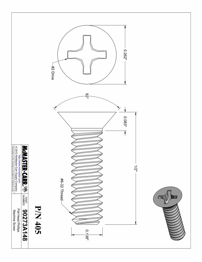
NU
MBER
PART
Information in this draw
ing is provided for reference only.
http://ww
w.m
cmaster.com
82°0.138"
1/2"
0.083"
#6-32 Thread
0.262"
#2 Drive
90273A148
Flat Head Phillips
Machine Screw
© 2012 M
cMaster-C
arr Supply C
ompany
P/N 405

NU
MBER
PART
Information in this draw
ing is provided for reference only.
http://ww
w.m
cmaster.com
5/16"7/64"
#6-32 Thread90480A007
Hex
Nut
© 2015 M
cMaster-C
arr Supply C
ompany
P/N: 406
P/N 406

2.75
46.00
6.00
16.00
30.00
40.00
4X .15 TH
RU ALL
.28 X 100°
SCA
LE 1:8
0.25
2.75
2.32
10°
SCA
LE 1:2
AA
BB
2 2
1 1
Transition BridgeAD
O N
OT SC
ALE D
RAW
ING
SHEET 1 OF 1
2/3/17D
aniel G.
UNLESS O
THERWISE SPEC
IFIED:
SCA
LE: 1:12W
EIGHT:
REVD
WG
. NO
.
407A SIZE
TITLE:
Senior Project Group 44
NA
ME
DA
TE
CO
MM
ENTS:
Q.A
.
MFG
APPR.
ENG
APPR.
CHEC
KED
DRA
WN
FINISH
MA
TERIAL: A
BS PLASTIC
INTERPRET G
EOM
ETRICTO
LERAN
CIN
G PER:
DIM
ENSIO
NS A
RE IN IN
CHES
TOLERA
NC
ES:
AN
GULA
R: MA
CH
TW
O PLA
CE D
ECIM
AL

NU
MBER
PART
Information in this draw
ing is provided for reference only.
http://ww
w.m
cmaster.com
3 ft.
1"1"
9/16"
1"2"1/2"
0.060"
2"1/8"
Pin D
ia.
0.245"
1658A7
Piano Hinge
Hinge uses #6 screw
s.w
ith Holes
© 2012 M
cMaster-C
arr Supply C
ompany
P/N 408

0 100 200 300 400 500 600 700 800 900Q - Volume Flow cfm (Actual)
0.00
1.00
2.00
3.00
4.00
5.00
6.00
7.00
8.00
Static Pressure (inwg)
0.00
0.50
1.00
1.50
Power: (HP)
0
20
40
60
80
100Total Eff. (%)
3450 rpm
AFR - Radial Bladed
Howden Industrial Fan Group
:::Date:
Fan Code
Item Reference: Wednesday, January 11, 2017
AF-10-R11027-6Project NameQuotation Number
Customer:::
Combination Data Sheet
2933 Symmes RoadFairfield, Ohio, 45014Tel: 513-874-2400 Fax: 513-870-6249
Website: www.howden.comEmail: [email protected]
Printed on Wednesday, January 11, 2017 Page 1 of 1 Selection Engine: 1.16.11.17a
AF-10-R11027-6 1
Description Qty
Fan
Fan Accessories
Sound Spectrum (Hz)63 125 250 500 1k 2k 4k 8k LpA @ 5 ft**
OverallLw*
Inlet* 89 90 96 95 92 190 211 105 211 198* Lw dB re 10 -12 W ** dBA re 2x10 -5 Pa
Terms and Conditions: This offer is made subject to the terms and conditionsdetailed on the accompanying letter.
Conditions SpecifiedVolume 0 cfmOutlet Pressure 0.00 inwg (static)Inlet Pressure 0.00 inwg (static)Density 0.075 lb/ft³Humidity 25 %Operating Temperature 70 °FConstruction Temperature 0 - 150 °F StandardAltitude 0 ftArrt 4 (dDirect)
Fan SelectionFan Code AF-10-R11027-6Fan Construction M1Volume 0 cfmPressure @ 0.075 lb/ft³ 0.00 inwg (static)Pressure @ 0.075 lb/ft³ 0.00 inwg (static)Power @ 0.075 lb/ft³ -1.000 HPPower @ 0.075 lb/ft³ -1.004 HPFan Speed 3450 rpmMax Speed 3800 rpmWheel Tip Speed 9885 fpmMax Safe Tip Speed 10888 fpmVelocity -197 fpm
P/N 501

File:C:\Users\melab2\Desktop\pressure.EES 2/10/2017 2:36:17 AM Page 1EES Ver. 10.096: #0552: for use only by students and faculty, Mechanical Engineering, Dept. Cal Poly State University
Conversion Factors
Convin = 12 [in/ft]
Convft = 12 [in/ft]
Convs = 3600 [s/hr]
Convmin = 60 [s/min]
Convgal = 7.48 [gal/ft3]
Convlbm = 32.2 [lbm·ft/s2·lbf]
Convin2 = 144 [in2/ft2]
Convhp = 550 [ft-lbf/s-hp]
g = 32.2 [ft/s2]
Convinwg = 27.7076 [inwg/psi]
Properties
U = 0.07493 [lbm/ft3]
Q = 0.000164 [ft2/s]
e = 0.000005 [ft]
Crectoround = 6 [-] Source: Table ER4-3 in 2001 ASHRAE Fundamentals
Cporosity = 100 [-] Source: Miller, 1990
Porous Plate
plateVelocityfpm = Qcfm
plenumAreain2 · Convft
2
platePressureDrop\ = Cporosity · U ·
plateVelocityfpm
Convlbm
Convmin2
Plenum
Qcfm = 820 [cfm]
plenumWidthin = 43 [in]
plenumDepthin = 12 [in]
plenumAreain2 = plenumWidthin · plenumDepthin
plenumPerimeterin = 2 · plenumWidthin + plenumDepthin
Appendix G: Pressure Drop Analysis in EES
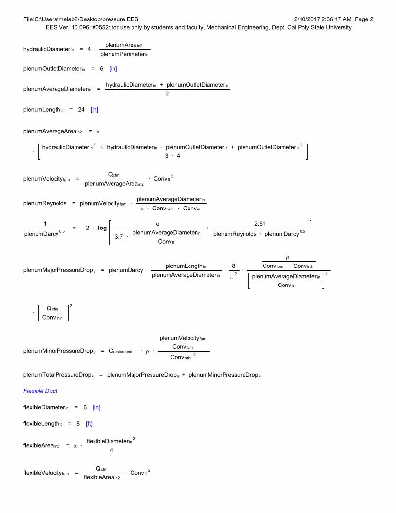
File:C:\Users\melab2\Desktop\pressure.EES 2/10/2017 2:36:17 AM Page 2EES Ver. 10.096: #0552: for use only by students and faculty, Mechanical Engineering, Dept. Cal Poly State University
hydraulicDiameterin = 4 · plenumAreain2
plenumPerimeterin
plenumOutletDiameterin = 6 [in]
plenumAverageDiameterin = hydraulicDiameterin + plenumOutletDiameterin
2
plenumLengthin = 24 [in]
plenumAverageAreain2 = S
· hydraulicDiameterin
2 + hydraulicDiameterin · plenumOutletDiameterin + plenumOutletDiameterin2
3 · 4
plenumVelocityfpm = Qcfm
plenumAverageAreain2 · Convft
2
plenumReynolds = plenumVelocityfpm · plenumAverageDiameterin
Q · Convmin · Convin
1
plenumDarcy 0.5 = – 2 · log
e
3.7 · plenumAverageDiameterin
Convft
+ 2.51
plenumReynolds · plenumDarcy 0.5
plenumMajorPressureDrop\ = plenumDarcy · plenumLengthin
plenumAverageDiameterin ·
8
S 2 ·
U
Convlbm · Convin2
plenumAverageDiameterin
Convft
4
· Qcfm
Convmin
2
plenumMinorPressureDrop\ = Crectoround · U ·
plenumVelocityfpm
Convlbm
Convmin2
plenumTotalPressureDrop\ = plenumMajorPressureDrop\ + plenumMinorPressureDrop\
Flexible Duct
flexibleDiameterin = 6 [in]
flexibleLengthft = 8 [ft]
flexibleAreain2 = S · flexibleDiameterin
2
4
flexibleVelocityfpm = Qcfm
flexibleAreain2 · Convft
2

File:C:\Users\melab2\Desktop\pressure.EES 2/10/2017 2:36:17 AM Page 3EES Ver. 10.096: #0552: for use only by students and faculty, Mechanical Engineering, Dept. Cal Poly State University
flexibleReynolds = flexibleVelocityfpm · flexibleDiameterin
Q · Convmin · Convin
1
flexibleDarcy 0.5 = – 2 · log
e
3.7 · flexibleDiameterin
Convft
+ 2.51
flexibleReynolds · flexibleDarcy 0.5
flexiblePressureDrop\ = flexibleDarcy · flexibleLengthft · Convft
flexibleDiameterin ·
8
S 2 ·
U
Convlbm · Convin2
flexibleDiameterin
Convft
4 ·
Qcfm
Convmin
2
Total
totalPressureDrop\ = platePressureDrop\ + plenumTotalPressureDrop\ + flexiblePressureDrop\
totalPressureDropinwg = totalPressureDrop\ · Convinwg
SOLUTIONUnit Settings: Eng F psia mass degConvft = 12 [in/ft]Convgal = 7.48 [gal/ft3]Convhp = 550 [ft-lbf/s-hp]Convin = 12 [in/ft]Convin2 = 144 [in2/ft2]Convinwg = 27.71 [inwg/psi]Convlbm = 32.2 [lbm·ft/s2·lbf]Convmin = 60 [s/min]Convs = 3600 [s/hr]Cporosity = 100 [-]Crectoround = 6 [-]e = 0.000005 [ft]flexibleAreain2 = 28.27 [in2]flexibleDarcy = 0.01554 [-]flexibleDiameterin = 6 [in]flexibleLengthft = 8 [ft]flexiblePressureDrop\ = 0.009734 [psi]flexibleReynolds = 212207 [-]flexibleVelocityfpm = 4176 [fpm]g = 32.2 [ft/s2]hydraulicDiameterin = 18.76 [in]Q = 0.000164 [ft2/s]platePressureDrop\ = 0.01479 [psi]plateVelocityfpm = 228.8 [fpm]plenumAreain2 = 516 [in2]plenumAverageAreain2 = 131.1 [in2]plenumAverageDiameterin = 12.38 [in]plenumDarcy = 0.01823 [-]plenumDepthin = 12 [in]plenumLengthin = 24 [in]plenumMajorPressureDrop\ = 0.00007627 [psi]plenumMinorPressureDrop\ = 0.003494 [psi]plenumOutletDiameterin = 6 [in]

File:C:\Users\melab2\Desktop\pressure.EES 2/10/2017 2:36:17 AM Page 4EES Ver. 10.096: #0552: for use only by students and faculty, Mechanical Engineering, Dept. Cal Poly State University
plenumPerimeterin = 110 [in]plenumReynolds = 94466 [-]plenumTotalPressureDrop\ = 0.00357 [psi]plenumVelocityfpm = 900.9 [fpm]plenumWidthin = 43 [in]Qcfm = 820 [cfm]U = 0.07493 [lbm/ft3]totalPressureDropinwg = 0.7785 [inwg]totalPressureDrop\ = 0.0281 [psi]
No unit problems were detected.

For θ > 45o and β = Area Ratio
𝐾𝐶 = 0.5(1 − 𝛽2)θ𝛽4
Given a height of 18”, the plenum insert will have a height of 17.94”
For a plenum of 24” in height, θ decreases to 83.7o
Using KC above, the percent difference in head loss coefficients is as follows:
% = (1 − 𝐾24𝐾18
) ∗ 100 = (1 −√sin(83.7
2 )
√sin(100.22 )
) ∗ 100 ≅ 𝟔. 𝟕%
Therefore, the 24” plenum has a head loss coefficient for the contraction 6.7% less than the 18” plenum,
which is a significant value.
21.44”
17.94”
100.2o
Appendix H: Plenum Insert Angle Analysis

Wind Tunnel Boundary Layer Removal Device Testing Procedures
Manufacturing and Test Review May 12, 2017
Created by: Daniel Glover, Liam Madden, and Robby Cabri
Appendix I: Detailed Testing Procedures

Introduction This manual describes all of the necessary test plans and procedures to verify our group’s prototype boundary layer removal device for the rolling-road wind tunnel on campus. It details all of the steps needed to install the device, prepare the wind tunnel for test procedures, and how to conduct test procedures and collect the necessary data. While all of the following test procedures are important in evaluating the effectiveness of the physical prototype, the most important result is the size of the boundary layer on the belt of the rolling road, as the device was designed to essentially remove any boundary layer buildup at that point. Test Procedure #1: Setting up the device Description: This procedure describes the process of taking the fully-manufactured device and installing it into the wind tunnel’s framing system
1. Take T-Slot linear bearings and use mounting fasteners to fix the bearings to the interior vertical support columns of the wind tunnel ahead of the rolling road.
2. Secure prototype’s lower framing assembly and fix the bearings to the framing assembly using supplied hardware.
3. Remove lid subassembly from prototype, and manually place plenum in framing through the wind tunnel test section.
- Note: Leave side-mounted T-slots attached to plenum when performing this step. 4. Fix the plenum to the prototype’s framing using the 5/16” T-slots hardware supplied with the
device. 5. Once the plenum and framing are in place, fix the lid subassembly to the plenum using the
mounting fasteners and associated T-slots hardware. 6. Use linear bearings to raise or lower the transition bridge to the same height of the rolling road. 7. Once device is installed and positioned accordingly, use worm gear clamps to affix the flexible
aluminum ducting to the bottom of plenum, leading to the suction fans underneath the tunnel. 8. Ensure that all components are fully secured prior to moving forward with any tests. 9. Briefly run the fans at the desired power to ensure that no loose parts or fasteners can cause any
problems during testing. Test Procedure #2: Perform boundary layer measurements in tunnel contraction Description: This procedure describes the process of taking detailed boundary layer measurements of the boundary layer buildup in the contraction of the tunnel, upstream of the fully installed prototype.
1. Position pitot-static boundary layer probe in the middle of the tunnel, upstream of the solid scoop. 2. Once the probe is in place, begin running the wind tunnel at the required wind speed and start the
data acquisition system hooked up to the probe. 3. Take measurements until the measured wind speed is ~99% of the given free speed, moving in
small increments to obtain as many data points as possible.

4. If necessary, shift probe laterally around the width of the tunnel and repeat step 3 to get new set of boundary layer data.
5. Once collection process is over, power down tunnel and remove probe as necessary. Test Procedure #3: Perform boundary layer measurements behind solid scoop Description: This procedure describes the process of taking detailed boundary layer measurements of the remaining boundary layer after the scoop, to determine whether a sufficient amount of air is redirected into the room by the scoop. The procedure is essentially the same as for test procedure #2.
1. Position pitot-static boundary layer probe in the middle of the tunnel, immediately downstream of the solid scoop.
2. Once the probe is in place, begin running the wind tunnel at the required wind speed and start the data acquisition system hooked up to the probe.
3. Take measurements until the measured wind speed is ~99% of the given free speed, moving in small increments to obtain as many data points as possible.
4. If necessary, shift probe laterally around the width of the tunnel and repeat step 3 to get new set of boundary layer data.
5. Once collection process is over, power down tunnel and remove probe as necessary. Test Procedure #4: Perform boundary layer measurements downstream of porous plate Description: This procedure describes the process of taking detailed boundary layer measurements of the remaining boundary layer after the porous plate, to determine whether a sufficient amount of air is removed by the fan. The procedure is essentially the same as for test procedure #2.
1. Position pitot-static boundary layer probe in the middle of the tunnel, on the edge between the porous plate and the transition bridge.
2. Once the probe is in place, begin running the wind tunnel at the required wind speed and start the data acquisition system hooked up to the probe.
3. Power up the suction fans and set to varying design points, moving in small increments. 4. Take measurements until the measured wind speed is ~99% of the given free speed, moving in
small increments to obtain as many data points as possible. 5. If necessary, shift probe laterally around the width of the tunnel and repeat step 3 to get new set
of boundary layer data. 6. Once collection process is over, power down tunnel and remove probe as necessary.
Test Procedure #5: Use fog machine to inspect for any undesirable aerodynamic disturbances Description: This procedure describes the use of the fog machine to check to see if any additional aerodynamic disturbances are created in the tunnel due to the presence of the installed prototype.
1. Hook up fog machine to proper source, and place near the inlet of the wind tunnel.

2. Begin running the tunnel to reach the desired wind speed, and wait until the tunnel is operating at steady-state.
3. Activate fog machine, and wait until fog flow is fully developed. 4. From multiple angles, look inside the tunnel’s test section and check if any abnormalities are
present in & around the area of the prototype. 5. Once the results have been recorded, power down the fog machine, followed by the wind tunnel
itself. Test Procedure #6: Perform boundary layer measurements on rolling road surface Description: This procedure describes the process of taking detailed boundary layer measurements of the remaining boundary layer after the full system, to determine whether the boundary layer has been removed. The procedure is essentially the same as for test procedure #2.
1. Position pitot-static boundary layer probe in the middle of the tunnel, on the edge between the transition bridge and rolling road.
2. Once the probe is in place, begin running the wind tunnel at the required wind speed and start the data acquisition system hooked up to the probe.
3. Power up the suction fans and set to varying design points, moving in small increments. 4. Take measurements until the measured wind speed is ~99% of the given free speed, moving in
small increments to obtain as many data points as possible. 5. If necessary, shift probe laterally around the width of the tunnel and repeat step 3 to get new set
of boundary layer data. 6. Once collection process is over, power down tunnel and remove probe as necessary.
Test Procedure #7: Analyzing data & producing conclusions Description: This procedure describes the analysis of the data from the previous six test procedures.
1. From test procedure #2, determine, at different wind tunnel speeds, the boundary layer height and the volumetric flowrate of the boundary layer component of the airflow.
2. From test procedures #3 and #5, determine whether the solid scoop is able to redirect most of the boundary layer.
3. If step 2 indicates that not enough boundary layer is removed, manufacture new solid scoops in order to fine tune the solid scoop. If step 2 indicates that air is actually sucked into the wind tunnel through the solid scoop, manufacture ducting that redirects the airflow through the solid scoop to the end of the wind tunnel.
4. From test procedure #4, determine the optimal design point for the fans for different wind speeds. If the fans are not capable of removing enough air, then purchase a larger fan.
5. From test procedures #5 and #6, determine whether the transition bridge is able to transition the air from the end of the porous plate to the rolling road without reintroducing a boundary layer. Also, make sure that air is not sucked up in the wind tunnel from below the transition bridge. If

the former issue occurs, consider a new transition bridge material; if the latter issue occurs, consider attaching a seal brush from the plenum to the rolling road, beneath the transition bridge.

Appendix J: Operator’s Manual Safety Notice: Do not connect or disconnect electrical components. Only a trained electrician can safely install and uninstall fans. Installing Framing and Plenum:
1. Fasten the eight quad profile brackets to the ends of the two 7 inch extrusions using the 5/16 inch fasteners.
2. Space the 5 ft extrusions 7 inches away from one another, parallel. Fasten the ends of the brackets to these extrusions as well, forming the base of the framing.
3. Unscrew one of the side plastic tabs from each of the four linear bearings. 4. Place the four linear bearings on the existing wind tunnel framing, sliding the plastic tabs back into
place, screwing them back in. 5. Slide the framing base onto the linear bearings and fasten it to each linear bearing with two 5/16
inch fasteners. 6. Hold the framing base and linear bearings in place with a jack on either side. 7. Fasten the four mounting tabs to the sides of the plenum. 8. Slide the circular portion of the plenum into the square space in the middle of the framing base so
that the plenum rests on top of the framing base. 9. Fasten the mounting tabs onto the framing base.
Assembling and Installing Lid:
1. Screw four of the screws through the countersunk holes in the transition bridge, through the piano hinge, and into four of the nuts. Likewise, do this for the porous plate.
2. Slide boundary layer scoop fasteners through the holes in the porous plate and screw nuts on them on the bottom side.
3. Place assembled lid on top of the plenum 4. Fasten the lid to the lid extrusions using three fasteners on each side.
Attaching Fans:
1. Place flexible ducting over the circular outlet of the plenum, with the o-ring over it. 2. Tighten the o-ring, fixing the flexible ducting to the plenum. 3. Connect other side of the flexible ducting to the fans (again, the fans should be electrically hooked
up by a professional). Preparing for Test:
1. Remove one foot long wood board immediately above the plenum. 2. Raise the plenum framing so that the top of the plenum is just below the wind tunnel floor.
ME 428/429/430 Senior Design Project - Final Report 91

3. Raise the rolling road. 4. Attach lid. 5. Turn on fans and wind tunnel.
Returning Wind Tunnel to Normal After a Test:
1. Remove lid. 2. Lower rolling road and plenum. 3. Return wood board to the wind tunnel floor.
ME 428/429/430 Senior Design Project - Final Report 92

References [1] Munson, Okiishi, Huebsch, Rothmayer, “Flow Over Immersed Bodies,” in Fundamentals of Fluid Mechanics , 7th ed. Hoboken, NJ,: John Wiley & Sons, 2013, ch. 9, sec. 2, pp. 489–512. [2] Thomas Elmer Farrell, “Development of a New Boundary Layer Control Technique for Automotive Wind Tunnel Testing,” M.S. thesis, Department of Aerospace Engineering, Wichita State University., Wichita, Kansas, 2005
[3] Windshear, Inc.. (2010). Windshear Information Brochure [Online]. Available FTP: http://www.windshearinc.com/ Directory: /flash/Windshear_brochure/pdf/ File: WSI_Brochure.pdf [4] Walter, Joel (2012). The Windshear Rolling Road Wind Tunnel, SAE International, Concord, NC [5] Auto Research Center, Inc.. (2010). The ARC Moving Ground Wind Tunnel [Online]. Available FTP: http://www.arcindy.com/ Directory: /wind-tunnel.html [6] McKiller, Walter, Greslin (2012). The Honda R&D Americas Scale Model Wind Tunnel, SAE International, Raymond, Ohio [7]"Cal Poly PROVE Lab." Cal Poly PROVE Lab. California Polytechnic State University, n.d. Web. 12 Nov. 2016. http://www.provelab.com/ [8] http://www.supplyhero.com/images/T/7659_7669_S.JPG [9] Miller, D.S. (1990). Internal Flow Systems , 2nd Edition, Gulf Publishing Company, Houston, TX. [10] Howden American Fan Company (2016). AF Cast Aluminum Pressure Blowers [Online]. Available FTP: http://www.americanfan.com/images/literature/product-info/CastAluminum.pdf [11] 2001 ASHRAE Handbook: Fundamentals , ASHRAE.
ME 428/429/430 Senior Design Project - Final Report 93