leader in breathing pacemakers instruction manual · this is a digital copy ... to signify that the...
TRANSCRIPT

Instruction Manualfor the
AveryBreathing Pacemaker
System
902AAntenna
Avery Biomedical Devices, Inc.61 Mall DriveCommack, NY 11725-5725 USAPhone: 631-864-1600, Fax: 631-864-1610
Leader in Breathing Pacemakers
www.averybiomedical.com
I-110AReceiver
E377-05Electrode
Advena Ltd.Pure O�ces, Plato Close,Warwick, CV34 6WE UKEmail: [email protected]
0086
6025-AB
ExternalAntenna
ExternalTransmitter
Electrode
Receiver
Diaphragm
Lung
Mark IVTransmitter
C
M
Y
CM
MY
CY
CMY
K
6025-AB Cover.pdf 1 7/22/2016 11:36:24 AM
THIS IS A DIGITAL COPY
The contents of this document are identical to the printed
version (6025-AB) distributed to patients, caregivers and
physicians who use the Implanted Diaphragm Pacing
System. In the event of any changes, printed labeling and
package inserts supersede this document.
Copying, reproduction, modification and/or distribution of this
document for any purpose without the consent of Avery
Biomedical Devices, Inc. is strictly prohibited.
For additional copies and/or questions about this document, please contact Avery Biomedical Devices, Inc.

1
TABLE OF CONTENTS KEY:l - For Patients and other usersn - For Medical Professionals
PAGEln GENERAL CAUTIONS REGARDING BREATHING PACEMAKERS 2ln RECYCLING INFORMATION 2ln LABEL SYMBOLS 3ln INTRODUCTION AND GENERAL INFORMATION 5
System Overview 5Bene�ts of Diaphragm Pacing 5Answers to Some Commonly Asked Questions 6Regulatory Approval/Certi�cation 6Financial Considerations 6Indications 6Patient Selection 6Ordering Equipment 6Device Tracking Requirements 6
n PREOPERATIVE SCREENING 7ln MARK IV TRANSMITTER 8
External Controls, Indicators and Function 8Carrying the Transmitter 9Batteries 9
ln 902A / 902AL ANTENNAS 10Connection and Removal 10Antenna Care 10Intraoperative Use of Antennas 11
n IMPLANTED COMPONENTS 11n STERILIZATION PROCEDURES FOR NON CE IMPLANTS 12n RESTERILIZATION PROCEDURES FOR CE IMPLANTS 13n SURGICAL PROCEDURES 14
Anesthesia 14Cervical Approach for New Implants 14Thoracic Methods for New Implants 15Surgical Approach for Receiver Replacement 16Surgical Approach for Electrode Replacement 16Implanted Medical Device Registration Form 17
ln POSTOPERATIVE CARE AND INITIATION OF PACING 18Postoperative Care 18Diaphragm Reconditioning 19Transtelephonic Monitoring - TTM 19
ln TROUBLESHOOTING 20ln CUSTOMER SERVICE AND SHIPPING INSTRUCTIONS 21
Customer Service 21Shipping Instructions 21
ln WARRANTIES AND IDENTIFICATION 22Limited Warranty 22Patient Identi�cation Card 23
6025-AB DRAFT Content.indd 1 8/3/2016 1:58:40 PM

2
GENERAL CAUTIONS REGARDING BREATHING PACEMAKERS
RECYCLING INFORMATIONDispose of depleted batteries in accordance with the battery manufacturer instructions or local environmental recycling laws.In accordance with Directive 2002/96/EC of the European Union, waste electrical and electronic equipment (WEEE) should not be disposed of as unsorted municipal waste. Contact the ABD Customer Service Department for instructions on how to return transmitters that are no longer in use at no cost.
CAUTIONS
Failure of the diaphragm pacer could lead to respiratory arrest.
WARNINGS
Radio Frequency (RF) may interfere with demand-type cardiac pacemakers. If a cardiac pacemaker is involved, the cardiac pacemaker leads should be bipolar and the breathing pacemaker implant(s) should be at least 10cm from the cardiac pacemaker.
Magnetic Resonance Imaging (MRI), shock wave lithotripsy and therapeutic diathermy are contraindicated.
If use of a de�brillator is necessary, the implanted receiver and the phrenic nerve could be damaged.
Exposure to a powerful transmitter such as navigational, maritime or amateur communications may interfere with the operation of the pacer. According to U.S. F.C.C. and foreign tables of frequency allocation, transmissions in the 2 MHz region may include: Radio navigation (LORAN-A), mobile distress, and emergency position indicating radio beacon (EPIRB) for aircrafts.
A device for providing arti�cial ventilation by mask, mouth piece or tracheal tube should be available for those patients who are continually dependent on the phrenic pacemaker as an alternative to mechanical ventilation.
Exposure to therapeutic dosages of ionizing radiation may damage implanted components or interfere with the operation of the pacer. Any damage to the implanted components may not be immediately detectable.
Exposure of the implanted components to therapeutic levels of ultrasound energy should be avoided as an implanted device may inadvertently concentrate the ultrasound �eld and cause harm.
Any implant removed from one patient must not be reimplanted in another patient.
One patient’s transmitter must not be used for another patient.
Do not use any other diaphragm pacing, phrenic nerve stimulation or other stimulating equipment to power our diaphragm pacer implants. This voids warranty and could cause serious injury or death.
Close proximity to a cell phone may interfere with the operation of the pacer. Cell phones and WiFi-enabled devices should be kept a minimum of 10 cm from the implants.
The transmitter emits a low level of radio frequency output at 2 MHz which may interfere with other devices in its proximity running at the same frequency.
The transmitter should not be used within one meter of �ammable anesthetics or in oxygen-enriched environments.
Diaphragm pacing systems should not be used aboard commercial aircraft without prior clearance with the pilot or airline.
The safety of diaphragm pacing in pregnancy has not been established.
Infection may occur as a result of the surgical procedure, or in the postoperative period due to wound infection or septicemia. If unresponsive to antibiotics, removal of the implants may become necessary.
An apnea alarm should be provided to summon help should diaphragm pacer failure occur.
Federal (USA) law restricts this device to sale by or on the order of a physician.
Failure of the diaphragm pacing system can occur due to battery failure, broken battery connector wires, or intermittent antenna cable or connector, or component failure in the receiver, electrode wire, or external transmitter.
A permanent tracheostomy may be required to obtain adequate ventilation. Diaphragm pacing can induce or worsen upper airway obstruction. Augmentation of the force of inspiration and laryngeal and pharyngeal musculature is the probable cause.
6025-AB DRAFT Content.indd 2 8/3/2016 1:58:40 PM

3
LABEL SYMBOLS
Title: Manufacturer Reference: 5.1.1
Description:Indicates the medical device manufacturer, as de�ned in EU Directives 90/385/EEC, 93/42/EEC and 98/79/EC.
Title: Authorized representative in the European Community Reference: 5.1.2
Description: Indicates the Authorized Representative in the European Community.
Title: Date of Manufacture Reference: 5.1.3
Description: Indicates the date when the medical device was manufactured.
Title: Use-by date Reference: 5.1.4
Description: Indicates the date after which the medical device is not to be used.
Title: Batch code Reference: 5.1.5
Description: Indicates the manufacturer’s batch code so that the batch or lot can be identi�ed.
Title: Catalogue number Reference: 5.1.6
Description: Indicates the manufacturer’s catalogue number so that the medical device can be identi�ed.
Title: Serial number Reference: 5.1.7
Description: Indicated the manufacturer’s serial number so that a speci�c medical device can be identi�ed.
Title: Sterilized using aseptic processing techniques Reference: 5.2.2
Description: Indicates a medical device that has been manufactured using accepted aseptic techniques.
Title: Sterilized using steam or dry heat Reference: 5.2.5
Description: Indicates that a medical device that has been sterilized using steam or dry heat.
Title: Non-sterile Reference: 5.2.7
Description: Indicates a medical device that has not been subjected to a sterilization process.
Title: Do not use if package is damaged Reference: 5.2.8
Description: Indicates a medical device that should not be used if the package has been damaged or opened.
Title: Do not re-use Reference: 5.4.2
Description:Indicates a medical device that is intended for one use, or for use on a single patient during a single procedure.
Title: Consult instruction for use Reference: 5.4.3
Description: Indicates the need for the user to consult the instructions for use
Title: Caution Reference: 5.4.4
Description:Indicates the need for the user to consult the instructions for use for important cautionary information such as warnings and precautions that cannot, for a variety of reasons, be presented on the medical device itself.
Title: Not made with natural rubber latex Reference: Negates5.4.5
Description:Natural rubber latex is not used as a material in this medical device, as part of its manufacturing process, its container and/or its packaging.
ISO 15223-1:2012 - Medical devices -- Symbols to be used with medical device labels, labelling and information to be supplied -- Part 1: General requirements
Title: General Warning Sign Reference: W001
Description: To signify a general warning
Title: Refer to instruction manual/booklet Reference: M002
Description: To signify that the instruction manual/booklet must be read
ISO 7010:2011 - Graphical symbols -- Safety colors and safety signs -- Registered safety signs
6025-AB DRAFT Content.indd 3 8/3/2016 1:58:41 PM

4
LABEL SYMBOLS (Cont.)
Title: Product information; information point Reference: 2760
Description: To identify a place where information may be found, especially in an emergency
Title: General symbol for recovery/recyclable Reference: 1135
Description: To indicate that the marked item or its material is part of a recovery or recycling process.
ISO 7000 5th edition (2014) - Graphical symbols for use on equipment -- Registered symbols
Title: Type BF applied part Reference: 5333
Description: To identify a type BF applied part complying with IEC 60601-1
Title: Direct Current Reference: 5031
Description:To indicate on the rating plate that the equipment is suitable for direct current only; to identify relevant terminals
ISO 60417:2002 (Database) Graphical symbols for use on equipment
Title: MR Unsafe Reference: -
Description: An item that is known to pose hazards in all MR environments.
ASTM F2503:2013 - Standard Practice for Marking Medical Devices and Other Items for Safety in the Magnetic Resonance Environment
IPTitle: Ingress Protection Reference: -
Description:Degrees of protection provided by enclosures of electrical equipment against intrusion, dust, accidental contact, and water
IEC 60529:1989+AMD1:1999+AMD2:2013 – Degrees of protection provided by enclosures (IP Code)
Title: Waste Electrical and Electronic Equipment Reference: Figure 1
Description:Indicates adherence to the directive 2002/96/EC of the European Union that designates safe and responsible collection, recycling and recovery procedures for all types of electronic waste.
EN 50419:2006 - Marking of electrical and electronic equipment in accordance with article 11(2) of Directive 2002/96/EC (WEEE)
Title: Conformite Europeenne Reference: Annex B(d)
Description: Conformity marking for certain products sold within the European Economic Area
Council Decision 93/465/EC - CE - Conformity Marking
Rx OnlyTitle: Prescription Use Only Reference: -
Description: Federal law restricts this device to sale by or on the order of a physician.
Food and Drug Administration (FDA) Guidance for Industry - Alternative to Certain Prescription Device Labeling Requirements (2000)
6025-AB DRAFT Content.indd 4 8/3/2016 1:58:41 PM

5
INTRODUCTION AND GENERAL INFORMATIONSystem OverviewThe Diaphragm Pacing System is an implantable diaphragmatic/phrenic nerve stimulator that provides support for patients with chronic ventilatory insu�ciency whose diaphragm, lungs and phrenic nerves have residual function.
The application of repetitive stimulus patterns to the phrenic nerves causes smooth, rhythmic contractions of the diaphragm, which result in the inhalation of air into the lungs. The pacing system consists of electrodes implanted near the phrenic nerves, radio receivers implanted in subcutaneous pockets and an external transmitter/antenna assembly that provides power to the system via 9-Volt batteries.
The external transmitter and antenna send energy and stimulus information to the passive receiver implant. The receiver translates radio waves into stimulating pulses that are delivered to the phrenic nerve by the electrode. The diaphragm muscle contracts and produces the inhalation phase of breathing. The transmitter then stops generating signals, which allows the diaphragm to relax and exhalation occurs. This cycle of signals followed by no signals is repeated automatically by the transmitter, producing a more natural breathing pattern. See Figure 1.
The transmitter contains the controls used to individually adjust the parameters of stimulation to suit each patient. Since 1968, over 2,000 phrenic nerve implants have been performed throughout the world. Patients from several months of age to over age 80 years have been successfully implanted and paced long term. Many patients have been successfully paced for more than 20 years and the longest patients have been pacing continually for over 40 years.
Bene�ts of Diaphragm PacingDiaphragm pacing provides physiological respiratory function far superior to that provided by mechanical ventilators since the inhaled air is drawn into the lungs by the musculature, rather than being forced into the chest under mechanical pressure. The bene�ts of diaphragmatic pacing include:
• cost e�ectiveness because patients can live outside of hospitals and the cost of a ventilator and its disposables is eliminated.
• lower infection rate due to reduction in suctioning, elimination of external humidi�er and ventilator circuits and the possibility of tracheostomy tube removal (some patients have had their tracheostomy closed).
• improved venous return (negative, not positive pressure).
• natural breathing and speech.• ease of eating and drinking.• increased patient mobility.• unobtrusive use due to the small size of external
components and totally silent operation.
Table 2. System Components
ItemName
Transmitter
Antennas
Receivers
Electrodes
Transtelephonic Monitoring Transmitter
Carrying Case
QuantityProvided
1-2
6 -10
2
2
1
1-2
ModelNumber
Mark IV
902A or 902AL
I-110A (Monopolar)
E-377-05(Monopolar)
TTM
N/A
Figure 1. Bilateral Pacing System
t Antenna
t Radio Transmitter
INTERNAL l
Diaphragm l
Lung l
Electrode l
Radio Receiver l
Phrenic Nerve l
t EXTERNAL
6025-AB DRAFT Content.indd 5 8/3/2016 1:58:41 PM

6
INTRODUCTION AND GENERAL INFORMATION (Cont.)Answers to Some Commonly-Asked QuestionsOngoing experience with diaphragm pacing disproves some of the concerns expressed by early investigators in the �eld. Years of follow-up show that diaphragm pacing:
• does not “burn out” nerves/muscles in normal operation.• can provide safe and e�ective bilateral pacing twenty-four
hours per day.• can permit decannulation and discontinuation of
tracheostomy tubes in selected patients.• can provide unilateral pacing where bilateral pacing is not
possible due to destruction of the other phrenic nerve.• can provide safe operation near properly functioning
microwave ovens and other equipment.
Regulatory Approval / Certi�cationThis equipment has full US FDA PMA approval. It complies with requirements of the European Directive for active implantable medical devices (90/385/EEC). The EC Declaration of Conformity is based on an approved ISO-13485 quality system and a design examination by a Noti�ed Body. Authorization to a�x the CE Mark was obtained in 1995 by TUV Rheinland. Currently, we have been certi�ed by BSI Management Systems (London, UK) since 2010. The equipment is marked:
Financial ConsiderationsOur equipment is reimbursed by Medicare and many private and government insurance plans around the world. When applying to carriers for approval (or “prior approval”), it is important to explain that diaphragm pacing may pay for itself in less than a month by permitting discharge to a less costly environment.
Unlike mechanical ventilators, pacers do not require expensive maintenance and disposable supplies, saving over $1,000 per month, every month for decades. The external Mark IV transmitter control unit comes with a three year warranty and the implanted receivers and electrodes both come with a �ve year warranty.
IndicationsThis device is indicated for persons who require chronic ventilatory support because of upper motor neuron respiratory muscle paralysis (RMP) or because of central alveolar hypoventilation (CAH) and whose remaining phrenic nerve, lung and diaphragm function is su�cient to accommodate electrical stimulation.
Candidates for diaphragm pacing include, but are not limited to, patients who have:
• central alveolar hypoventilation. • decreased day or night ventilatory drive (i.e. sleep apnea,
Ondine’s curse).• brain stem injury or disease. • spinal cord injury or disease.
Patient SelectionDiaphragm pacing is generally indicated for prospective candidates who have:
• functional lungs and diaphragm muscle.• Intact or repaired phrenic nerves.• absence of infection.• a clear and adequate upper airway (including
nasopharynx, pharynx and larynx).• adequate physical caregiver quality and availability
including nursing, family support and medical care.
Implantation of a new diaphragm pacing system can be done on an inpatient or outpatient basis, depending on the patient’s, hospital’s or surgeon’s preference and rules of the appropriate insurance carrier. The hospital or clinic should have support facilities and personnel to be able to care for the type of patient involved. For example, a patient with quadriplegia disability may need lifting, turning or mechanical ventilatory support.
The surgical procedure usually takes one to four hours depending on patient, surgical experience, anesthesia support and facility sta�ng.
Ordering EquipmentOnce the surgeon has decided on a surgical approach, please contact us to order the appropriate equipment and arrange for one of our representatives to be present at the operation.
Equipment should be selected according to the patient’s needs, the existence of previously implanted devices and presence or absence of a cardiac pacemaker. It is mandatory to inform us of the patient’s name and address at the time of ordering to facilitate future follow-up. The equipment can be shipped overnight by courier to most North American locations, and within a few days overseas.
Device Tracking RequirementsMedical Device Tracking regulations of the U.S. Food and Drug Administration require that we be noti�ed when a diaphragm pacing:
• system is implanted.• receiver or electrode is explanted. Include the date,
name, mailing address and telephone number of the explanting physician.
• patient dies.• device is returned.• device is permanently retired from use or otherwise
permanently discarded.
There are no risks associated with the disposal of the device as none of the components contain hazardous and/or toxic materials. Explanted components should be disposed of in accordance with hospital policy or autoclaved and returned to us for quality assurance testing and archiving.
6025-AB DRAFT Content.indd 6 8/3/2016 1:58:41 PM

7
PREOPERATIVE SCREENING
Patient Testing TechniquesTranscutaneous screening tests may produce “false negatives” especially if the laboratory relies solely on EMG techniques and has limited testing experience. For example, many sleep apneics who breathe spontaneously during the day have been falsely reported as “negative.” The most unequivocal test is to expose the nerve and stimulate directly using the nerve test probe.
Testing in quadriplegics may show nerve conduction with little to no diaphragm movement observed. Lack of immediate movement may be attributable to an unconditioned muscle due to prolonged dependency on mechanical ventilation. Months of stimulation may be required before su�cient diaphragm function returns.
Screening for diaphragm function may include one or more of the following:
• �uoroscopy to observe diaphragm movement in patients with some spontaneous ventilatory drive
• transcutaneous stimulation of the phrenic nerves in the neck in combination with the following to con�rm diaphragm movement:
a) electromyogram (EMG) techniques,b) �uoroscopy,c) measurement of phrenic nerve conduction time
(PNCT), and d) measurement of transdiaphragmatic pressure.
The simplest method of predicting nerve viability and diaphragm function is transcutaneous phrenic nerve stimulation with simultaneous �uoroscopy of the diaphragm and measurement of the phrenic nerve conduction time (PNCT).
The phrenic nerve is stimulated transcutaneously with a hand held cathode covered with saline or electrode jelly pressed against the skin overlying the anterior scalene muscle, above the clavicle and behind the lateralposterior border of the sternocleidomastoid muscle. The anode is best attached on the posterior cervical surface or between the scapulae.
The stimulator should be set to deliver a stimulus pattern composed of square wave pulses of 500 to 1,000 µseconds duration at the frequency of twenty pulses per second at a current level of 20 to 100 milliamperes. Using a spirometer and �uoroscopy, a tidal volume of more than 50 ml. and diaphragmatic movement in excess of 3.0 cm. is considered desirable in patients with no voluntary movement of the diaphragm.
When measuring PNCT, two surface electrodes are placed at the costal margin in the anterior axillary line in the eighth or ninth intercostal space and a ground electrode is placed on the xiphoid process. The conduction time from the site of phrenic nerve stimulation in the neck to the diaphragm action potential is recorded on a storage oscilloscope.
Normal PNCT is between 6 and 9 ms. (shorter in children). A prolonged PNCT of more than 11 ms. latency may suggest damage to the phrenic nerve, but the clinical signi�cance of this is uncertain.
u Failure of the diaphragm to contract when transcutaneous stimulation is applied to the phrenic nerve does not necessarily mean that the nerve will not respond to direct stimulation.
u De�nitive test of phrenic function is achieved via open dissection of the phrenic nerve.
u Ensure sleep apnea is central apnea, not obstructive apnea.
Cautions
6025-AB DRAFT Content.indd 7 8/3/2016 1:58:41 PM

8
Figure 3. Mark IV Transmitter
MARK IV TRANSMITTER
The Mark IV transmitter generates stimulus patterns and delivers them to the phrenic nerves via the external antennas, implanted receivers and electrodes. The Mark IV transmitter design employs two independent output stimulus generators, each with its own battery power source, external indicators and respiratory rate control (Figures 3 & 4). Although each stimulus generator is independent from the other, they are electronically linked to begin phrenic nerve stimulation simultaneously at the desired external respiratory rate setting.
Figure 4. Top Panel of Mark IV Transmitter
The independent stimulus generators provide for asynchronous stimulation (e.g. di�erent stimulus pulse widths, pulse intervals, etc.) that may be desirable in some patients in order to optimize their respiration. Optimization adjustments require access to the internal controls that can only be done in consultation with Avery personnel. The Mark IV transmitter is constructed of materials that minimize the possibility of accidental damage, but it is a delicate instrument and should be treated as such. The expected service life of the Mark IV transmitter is 10 years with a warranty of 3 years. There is no calibration, preventative or scheduled maintenance during the lifetime of the transmitter.
External Controls, Indicators and Function Adjustment of the external controls is performed on an individual basis by the physician, caregiver or patient as necessary. The description of the controls and indicators is as follows:
The Mark IV transmitter operates via direct current supplied by two (2) 9-volt alkaline batteries.
The Mark IV transmitter utilizes a Type BF applied part (antenna) that is isolated from other parts of the equipment.
“A” (Antenna) Indicator Light• Veri�es the stimulus output and antenna integrity for each
side of the transmitter by lighting during each inspiratoryinterval.
• Allows the physician, caregiver or patient to troubleshootloss of stimulation by using a good, spare antenna andobserving return of the indicator light.
Extreme impact, exposure to moisture, dirt or temperatures beyond its capability may damage the transmitter and a�ect its ability to function correctly. The transmitter can be cleaned using a damp cloth, making sure liquid does not enter the transmitter.
ON / OFF SwitchTurns the transmitter stimulus output on/off on each side. In earlier Mark IV transmitters, the left transmitter circuitry activates the external respiratory rate control knob. If the LEFT side is switched o� the external respiratory control knob is inactive and the transmitter will generate respiratory stimulus patterns at the default rate (9 breaths per minute) despite the external respiratory rate control knob setting. Contact the Customer Service Department to verify which side of the patient’s transmitter controls the front panel respiratory rate knob.
AMPLITUDE DialSets the level of stimulus output of each side of the transmitter, adjusting the patient’s tidal volume. Patients may notice the need to change the amplitude setting with routine changes from the supine to the upright position. This is a normal variation and each patient’s requirements will be di�erent.
RATE KnobSets the level of bilateral breaths per minute. For patients who are to be paced unilaterally, Contact the Customer Service Department to verify which side of the patient’s transmitter controls the front panel respiratory rate knob.
Antenna Indicator Rate KnobBattery Indicator
Antenna IndicatorBattery Indicator
Amplitude Dial
Antenna Connector
Amplitude Dial
Antenna Connector
u Do not drop.u Do not allow to become wet or be placed under a drip bag.u Turn the transmitter o� to change the batteries.u Do not allow unsupervised children to adjust the transmitter.u The internal transmitter controls should only be adjusted upon the
advice of the physician and by Avery personnel.u Repairs or modi�cations by anyone other than Avery personnel
could be dangerous. Such action may damage equipment, cause serious injury or death, and voids all warranties.
u If a sudden increase in amplitude dial setting (greater than 30% above normal setting) is required for e�ective pacing after new batteries have been installed, notify the patient’s physician immediately. The patient may have an infection or there may be a mechanical failure of the equipment.
u Do not exceed operating temperature range of +41°F to +99°F (+5°C to +37°C) because the pacer may fail to function at very high or low temperatures.
u If ambient temperature reaches +37°C, then measures should be taken to ensure antennas remain at +37°C or less as they are in contact with the skin.
u Do not steam sterilize. u Pets and pests should not be allowed in contact with the
transmitter.u The transmitter does not work while the batteries are being
changed.u Be sure to turn the transmitters ON when pacing and OFF when not
pacing.u For patients who are to be paced unilaterally, contact the Customer
Service Department to verify which side of the patient’s transmitter controls the front panel respiratory rate knob.
Cautions
Warnings
6025-AB DRAFT Content.indd 8 8/3/2016 1:58:42 PM

9
MARK IV TRANSMITTER (Cont.)“B” (Battery) Indicator Light• Veri�es the integrity of battery wires and power circuitry for
each side of the transmitter by lighting during each inspiratory interval, as long as adequate battery voltage remains.
• Provides adequate warning of battery failure; the transmitter continues to produce stimulus patterns for 48 hours after the battery indicator extinguishes.
• Alerts the physician, caregiver or patient of required battery replacement and prevents the installation of either a dead or inadequate battery.
Carrying the TransmitterA nylon carrying case is provided with the breathing pacemaker system. The case helps protect the antennas by supporting the strain relief area behind the connector, and protects the transmitter from water splashes and inadvertent changes to the front panel amplitude dials. The case has pockets designed to carry spare antennas, batteries and the patient identi�cation card. The case is provided with a nylon belt and integrated belts loops allowing it to be worn at the waist, carried over the shoulder, or fastened to other items, such as a wheelchair. It is recommended that the transmitter case be used at all times. Should you choose not to use the provided carrying case, ensure that the transmitter is always attached securely to protect it from being dropped, or becoming wet.
When replacing batteries:
Turn transmitter o�. The transmitter will not work while batteries are being changed. Failure to turn o� transmitter while changing batteries will result in damage to the internal circuits.
1. Turn the transmitter over and slide the button latch on the rear panel toward the center of the transmitter.
2. Lift the cover up and o�. Slide the batteries out of the case.
3. Carefully unsnap the batteries from the connector clip. Do not pull on the wires.
4. Ensure the polarity of the battery terminals line up correctly with the polarity of the terminals on the connector clip.
5. Press the connectors evenly and �rmly onto the contacts of the new batteries.
6. Replace the batteries in the battery compartment ensuring that the wires are placed inside the compartment.
7. Replace the rear panel by attaching the side without the button latch to the side rail �rst, pivoting the rear panel closed and closing the button latch by sliding it towards the side of the transmitter.
Batteries
The Mark IV transmitter requires two 9-volt batteries, one for each side of the transmitter, located in a compartment behind the rear panel. As battery voltage decreases, stimulus output decreases which then reduces tidal volume. When the battery indicator, located on the transmitter front panel no longer �ashes during inspiration, the battery voltage is inadequate and the battery needs to be replaced.
Adequate warning is provided and the transmitter will continue to function, however the functioning time is variable and battery replacement should be performed as soon as possible.
Dispose of depleted batteries in accordance with the battery manufacturer instructions or local environmental recycling laws.
Table 5b. Transport & Storage Conditions
ConditionStorage and TransportationHumidity Pressure
Range-20°C to +50°C10% to 90%, non-condensing70 to 106 kPa
Table 5a. Mark IV Transmitter Speci�cations
Speci�cation
Transmitter WarrantyBilateral Stimulus RedundancyLeft / Right Asynchronous RedundancyTransmitter Energy Source
Battery LifeBattery / Antenna IndicatorsTransmitter / Battery Weight Transmitter DimensionsRespiratory Rate
Default Respiratory RateInspiratory Period
Pulse Interval
Pulse WidthMinimum SlopeStimulus Amplitude
Carrier Frequency
Range or Value
3 YearsYesYes
9-Volt Battery (disposable alkaline, 2 each)> 400 HoursYes0.54 kg.146 mm x 25 mm x 140 mm6 to 24 breaths per minuteFactory Set to 12 9 breaths per minute1.2 to 1.45 secondsFactory Set to 1.340 to 130 millisecondsFactory Set to 50150 +/- 10 microsecondstrue zero000 to 999Output Factory Set to 8.0 to 10.5 VCE Output Factory Set to 8.0 to 13.5 VDial Factory set to 0002.05 megahertz
Adapters that plug into wall outlets in place of batteries should never be used. Use of these adapters could result in serious injury or death.
u Use only alkaline batteries such as “Duracell” MN1604, for its long life characteristics.
u Keep spare batteries on hand at all times. u Do not use any other type battery except in an emergency. u Carbon-zinc batteries are less expensive but have a shorter life and
are not recommended for diaphragm pacing. u Rechargeable 9-Volt batteries should not be used due to short life
and rapid decrease in battery voltage. u Remove batteries if transmitter is not used for extended periods.u Lithium ion batteries have been tested and, due to the cyclical nature
of the transmitters, do not provide the long life expected of them.
Cautions
Warning
u The transmitter does not work while the batteries are being changed.
6025-AB DRAFT Content.indd 9 8/3/2016 1:58:42 PM
10
902A / 902AL ANTENNAS
The antenna is a one meter long (two meters for 902AL) wire, covered with silicone rubber, with a loop of concentrically wound wire at one end and a metal connector at the other end. The antennas transfer the stimulus pattern from the transmitter transcutaneously to the implanted receivers and electrodes. Each system is shipped with multiple antennas, two for immediate use, the others as spares. Store the spare antennas in a dry place. Antennas carry a 3-month warranty. Proper care and gentle handling will make them last longer but they will eventually wear out. ABD recommends replacement of antennas every six months (expected service life).
Defective antennas must be replaced as required. It is also recommended to always have a spare pair available. Old antennas should be discarded, as they cannot be repaired. The antennas must be properly positioned directly over the implanted receiver for maximum operating e�ciency. The loop should lie �at against the skin. If the loop is not directly over the receiver, the radio signals reaching the receiver will not be full strength. Each antenna may be held in place with hypoallergenic adhesive tape. Apply tincture of benzoin �rst; after it dries tape the antennas to the skin. A suggested method for taping on the antenna loop is shown in Figure 6.
Alternatively, use elastic netting that �ts snugly or conforms to body shape, other adhesive dressings (i.e. steri-drape), elastic bandages or a gas-permeable dressing. An additional piece of tape applied to the antenna cable just below the loop may help with stabilization. A thin layer of polypropylene or similar material may alleviate skin irritation due to perspiration when placed beneath the antenna. The amplitude dial settings on the transmitter may have to be adjusted accordingly to maintain proper ventilation.
Antenna Care• Each antenna wire should run in a straight line or be gently
looped between the receiver site and the transmitter. Do not bend or kink the wire.
• The point of greatest stress is the antenna/connector joint; keep this area free from bending or pulling.
• Wash antennas periodically with warm water and mild soap. Do not soak. Rinse and dry thoroughly.
• Do not allow the metal connectors to become wet. • Adhesive tape buildup can be removed with an alcohol-
dampened cloth. • The stimulator may not work properly if dirt accumulates in
the antenna plugs or transmitter connector sockets.
Antenna Removal1. Turn transmitter o�.2. Hold the transmitter �rmly.3. Grasp the antenna connector only by the rough collar
(barrel) of the metal plug.4. Do not pull on the wire or its rubber covering. Don’t rotate
the metal plug when it is in the transmitter connector.5. Pull straight up and out. Do not twist it or force it to
disconnect.6. With routine use the antennas should not need to be
disconnected from the transmitter frequently. It is preferable to remove the antennas from the skin and leave them attached to the transmitter.
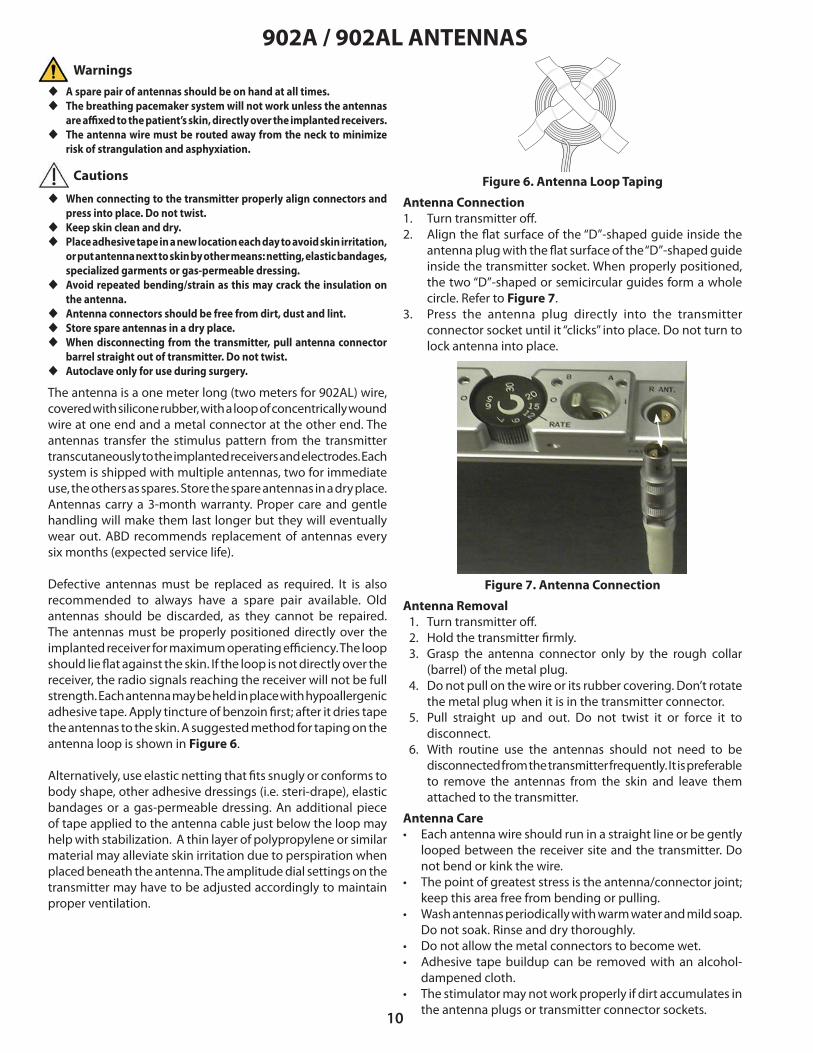
Antenna Connection1. Turn transmitter o�.2. Align the �at surface of the “D”-shaped guide inside the
antenna plug with the �at surface of the “D”-shaped guide inside the transmitter socket. When properly positioned, the two “D”-shaped or semicircular guides form a whole circle. Refer to Figure 7.
3. Press the antenna plug directly into the transmitter connector socket until it “clicks” into place. Do not turn to lock antenna into place.
Figure 6. Antenna Loop Taping
Figure 7. Antenna Connection
u A spare pair of antennas should be on hand at all times.u The breathing pacemaker system will not work unless the antennas
are a�xed to the patient’s skin, directly over the implanted receivers.u The antenna wire must be routed away from the neck to minimize
risk of strangulation and asphyxiation.
Warnings
Cautions
u When connecting to the transmitter properly align connectors and press into place. Do not twist.
u Keep skin clean and dry.u Place adhesive tape in a new location each day to avoid skin irritation,
or put antenna next to skin by other means: netting, elastic bandages, specialized garments or gas-permeable dressing.
u Avoid repeated bending/strain as this may crack the insulation on the antenna.
u Antenna connectors should be free from dirt, dust and lint. u Store spare antennas in a dry place.u When disconnecting from the transmitter, pull antenna connector
barrel straight out of transmitter. Do not twist.u Autoclave only for use during surgery.
6025-AB DRAFT Content.indd 10 8/3/2016 1:58:42 PM

11
IMPLANTED COMPONENTS
ReceiversThe implanted I-110A receiver, shown in Figure 8, is a small disc-shaped device that contain electronic circuitry embedded in epoxy resin and coated with silicone rubber. Each receiver converts the stimulus energy from the antennas into distinct stimulus pulses and transfers them to the electrodes attached to the phrenic nerves.
The monopolar receiver (Model I-110A) has a single connector, uses an integrated anode (horseshoe shaped) plate and the patient’s body tissue to complete the electrical stimulus circuit.
u Handle only with powder-free gloves.
Figure 8. I-110A (Monopolar) ReceiverDimensions: Diameter 30mm, Thickness 9mm, Weight 7.5 gm
Figure 9. E-377-05 (Monopolar) ElectrodeWire Length: 500 mm
ElectrodesThe implanted electrode, shown in Figure 9, is composed of highly �exible, stainless steel �bers insulated by silicone rubber, with a platinum nerve contact on one end and a connector that mates to the receiver, on the other end. Each electrode accepts the stimulus pulses from the receiver and transfers them to the phrenic nerve, causing the diaphragm muscle to contract.
The monopolar electrode (Model E-377-05) is composed of a single wire assembly.
Anode
902A / 902AL ANTENNAS (Cont.)Antenna SterilizationSterilization should take place in accordance with established hospital policy. In the absence of an established policy, or at a minimum, the following procedures may be followed:
1. Remove antenna from packaging using powder-free gloves.
2. Steam autoclave only. Place in an open tray on a lint free cloth. Set autoclave to the following settings:
• Temperature/Pressure: 270°F (132°C) / 30 PSI (206.8 kPa)
• Use “pre-vacuum” method if available.• Do not exceed 275°F (135°C).
• Exposure Time: 10 minutes• Drying Time: 10 minutes
Autoclave ONLY if intraoperative testing is to be performed. Autoclaving may shorten antenna life.
Intraoperative Use of AntennasThe 902AL antennas should be used with the patient’s Mark IV transmitter for intraoperative testing. This can be achieved by:
1. Placing the loop end of the antenna into a sterile, single-use instrument drape such as those used for endoscopic instrumentation.
2. Sterilize the antenna via steam autoclave.
It is recommended that at least two antennas be prepared for use in the sterile �eld so that a spare would be immediately available.
Once sterile, the loop end of the antenna should be introduced into the sterile �eld and the connector end shall remain outside of the sterile �eld so that it can be mated to the Mark IV transmitter. The connector end of the antenna shall remain outside of the sterile �eld for the duration of the procedure.
Warning
6025-AB DRAFT Content.indd 11 8/3/2016 1:58:42 PM

12
STERILIZATION PROCEDURES FOR NON CE IMPLANTSSterilization of equipment should take place in accordance with established hospital policy for implants. In the absence of an established policy, or at a minimum, the following procedures may be followed:
Receivers (Model I-110A )
1. Remove receiver from box and packaging using powder-free gloves.
2. Steam autoclave only. Place in an open tray on a lint free cloth. Set autoclave to the following settings:
• Temperature/Pressure: 270°F (132°C)/30 PSI (206.8 kPa) • Use “pre-vacuum” method if available. • Do not exceed 275°F (135°C).• Exposure Time: 10 minutes• Drying Time: 10 minutes
Electrodes (Model E-377-05)
1. Remove electrode from box and packaging using powder-free gloves.
2. Steam autoclave only. Place in an open tray on a lint free cloth. Set autoclave to the following settings:
• Temperature/Pressure: 270°F (132°C)/30 PSI (206.8 kPa) • Use “pre-vacuum” method if available. • Do not exceed 275°F (135°C).• Exposure Time: 10 minutes• Drying Time: 10 minutes
Antennas (Model 902A, Model 902AL)
1. Remove antennas from box and packaging using powder-free gloves.
2. Steam autoclave only. Place in an open tray on a lint free cloth. Set autoclave to the following settings:
• Temperature/Pressure: 270°F (132°C)/30 PSI (206.8 kPa) • Use “pre-vacuum” method if available. • Do not exceed 275°F (135°C).• Exposure Time: 10 minutes• Drying Time: 10 minutes
Autoclave ONLY if intraoperative testing is to be performed. Autoclaving may shorten antenna life.
Transmitters (Mark IV, TTM Data Transmitter)
ABSOLUTELY CANNOT BE STEAM AUTOCLAVED.
Sterilization of the transmitter is not required for any surgical procedure.
Should sterilization be desirable for any other reason, ethylene oxide (ETO) gas can be used.
Prior to sterilization:
• Remove the following items from its boxes or packages using powder-free gloves:
a) electrodes,b) receivers, andc) two (2) antennas
u Sterilization temperature should not exceed 275°F (135°C). u Ultrasonic cleaning can damage receivers and electrodes.u Never gas sterilize receivers or electrodes. Residual ethylene oxide
or other chemicals can cause severe tissue reaction.
Warnings
Cautions u Steam autoclave required system components.u Remove all packaging material from items to be sterilized.
Refer to the device labeling and package inserts for current sterilization procedures. In the event of any changes, device labeling and package inserts supersede the procedures shown in this manual.
Items with long lead lengths (i.e. electrodes, antennas) should be placed �at and coiled so that the leads do not lie on top of each other.
NOTE: Any component removed from its outer bag may not be returned to us for credit. Items that are returned undamaged, in the original sealed package and received within 15 days of shipment will receive credit less 20% to cover the expense of reinspection, repackaging and restocking. We recommend that all items be left in the packaging until they are known to be needed, at which time they should be removed from the packaging, and (as appropriate) sterilized.
Use only powder-free gloves when handling because residual powder grains can damage nerve tissue. Bare skin contact is not permitted.
Do not gas sterilize receivers, electrodes, antennas or accessories. Items must be segregated if gas sterilized by mistake and returned to Avery Biomedical Devices for archiving.
No cleaning of components is required prior to sterilization.
6025-AB DRAFT Content.indd 12 8/3/2016 1:58:42 PM

13
RESTERILIZATION PROCEDURES FOR CE IMPLANTS
The implantable I-110A receivers and E377-05 electrodes were sterilized using steam sterilization before shipment. Inspect the sterile package for seal integrity and damage to the package before opening and using the contents. If there is any uncertainty regarding the sterility of the components, they can be resterilized at the hospital.
Prior to resterilization, remove the items from its boxes and packaging using powder-free gloves
ABD cannot accept the responsibility for the resterilization of any components. If the decision is made to resterilize, such resterilization should take place in accordance with established hospital policy for implants. In the absence of an established policy, or at a minimum, the following procedures may be followed:
Receivers (Model I-110A)
1. Remove receiver from box and packaging using powder-free gloves.
2. Steam autoclave only. Place in an open tray on a lint freecloth. Set autoclave to the following settings:
• Temperature/Pressure: 270°F (132°C) / 30 PSI (206.8 kPa).• Use “pre-vacuum” method if available.• Do not exceed 275°F (135°C).
• Exposure Time: 10 minutes• Drying Time: 10 minutes
Electrodes (Model E-377-05)
1. Remove electrode from box and packaging using powder-free gloves.
2. Steam autoclave only. Place in an open tray on a lint freecloth. Set autoclave to the following settings:
• Temperature/Pressure: 270°F (132°C) / 30 PSI (206.8 kPa)• Use “pre-vacuum” method if available.• Do not exceed 275°F (135°C).
• Exposure Time: 10 minutes• Drying Time: 10 minutes
Transmitters (Mark IV, TTM Data Transmitter)
ABSOLUTELY CANNOT BE STEAM AUTOCLAVED.
Sterilization of the transmitters is not required for any surgical procedure
Warnings
Cautions
u Steam autoclave required system components.u Remove all packaging material from items to be sterilized.
Refer to the device labeling and package inserts for current sterilization procedures. In the event of any changes, device labeling and package inserts supersede the procedures shown in this manual.
Items with long lead lengths (i.e. electrodes, antennas) should be placed �at and coiled so that the leads do not lie on top of each other.
Do not gas sterilize receivers, electrodes, antennas or accessories. Items must be segregated if gas sterilized by mistake and returned to Avery Biomedical Devices for archiving.
NOTE: Any component removed from its outer bag may not be returned to us for credit. Items that are returned undamaged, in the original sealed package and received within 15 days of shipment will receive credit less 20% to cover the expense of reinspection, repackaging and restocking. We recommend that all items be left in the packaging until they are known to be needed, at which time they should be removed from the packaging, and (as appropriate) sterilized.
Use only powder-free gloves when handling because residual powder grains can damage nerve tissue. Bare skin contact is not permitted.
u Sterilization temperature should not exceed 275°F (135°C). u Ultrasonic cleaning can damage receivers and electrodes.u Never gas sterilize receivers or electrodes. Residual ethylene oxide
or other chemicals can cause severe tissue reaction.
No cleaning of components is required prior to sterilization.
6025-AB DRAFT Content.indd 13 8/3/2016 1:58:43 PM

14
SURGICAL PROCEDURES
u Do not administer muscle relaxants (or short-acting agents) as its use may a�ect the ability to test the diaphragm function intraoperatively.
u Administer antibiotics intraoperatively and for an appropriate period postoperatively.
u Do not perform surgery if the patient has any sign of infection.
Anesthesia may not be required if the patient is insensate. Patients with sensation in the chest will need local anesthesia. However, depending on the age of the patient, his/her ability or willingness to cooperate or preference of the surgeon or anesthesiologist, general anesthesia may be chosen.
The usual method is to intubate the patient endotracheally for the duration of the surgery with the tracheostomy tube removed and the stoma cleaned and sealed o�. Alternatively, an endotracheal tube can be placed through the stoma and the whole area sealed o� with a transparent adhesive drape. This may be required in patients who have undergone C1-C2 stabilization. If necessary, anesthesia can be provided through the tracheostomy tube if the area and the tubes are sealed o� using a transparent adhesive drape.
u This surgical site may not be desirable if tracheal stoma is present or lung infection suspected.
u Begin antibiotic administration 24 hours prior to surgery.u Verify implantable components are sterile.u Mark patient’s skin with sterile pen for appropriate receiver pocket
location when patient is lying �at.u Injury to the phrenic nerves may occur due to surgical trauma,
interruption of blood supply, foreign body reaction and infection.u Place receivers between dermal and muscle layers during implant to
prevent erosion through skin.u Place anode plate downward towards the rib cage.u Wipe connector contacts clean with dry sponge prior to mating.u Do not place receivers too high on chest wall as to cause electrode
wire fatigue from repeated arm / shoulder movement (if applicable).u Ensure adequate receiver separation to prevent antenna loop overlap.u Make loops in the electrode wire near the nerve and receiver to provide
adequate strain relief.u Test receiver and electrode function after mating.u Place a nonabsorbable suture tie around mated connectors.u Ensure wires do not pass beneath incisions.u Test receiver and electrode function again after closing incision.u If di�culty is encountered in identifying the phrenic nerve or in
avoiding the stimulation of other nerves in the cervical region, then it may be prudent to discontinue the cervical approach and consider using the thoracic approach.
u Infection may occur as a result of the surgical procedure, or in the postoperative period due to wound infection or septicemia. If unresponsive to antibiotics, removal of the implants may become necessary.
u Do not plicate diaphragm.
Cervical Approach for New Implants
Anesthesia 1. Prep and drape in the usual fashion.2. Use two 5 cm. incisions 2 cm. above and parallel to the
mid-portion of each clavicle.3. Divide platysma and identify the lateral border of the
sternocleidomastoid muscle.4. Medially retract sternocleidomastoid muscle.5. Identify prescaline fat pad laterally.6. Retract scalenus anticus (and internal jugular vein) laterally. 7. Use a nerve test probe to identify phrenic nerve. 8. Expose phrenic nerve via meticulous dissection.9. Gently create a tunnel under the nerve, 10-12 mm. in width
with a right-angled clamp. 10. Slide electrode under phrenic nerve and lay nerve in groove
of electrode. 11. Suture electrode to underlying tissue. Take care that the
nerve is lying straight within the electrode after retractors are removed.
12. Create a subcutaneous pocket approximately 5 cm. below the clavicle for receiver.
13. Tunnel electrode cable connector beneath skin to receiver pocket area.
14. Leave slack on the electrode wire at the site of insertion near the phrenic nerve.
15. Wipe connector clean with dry sponge.16. Attach electrode connector to receiver. Insert receiver into
pocket (anode disc side down).17. Test receiver and electrode function after mating.18. Place a single nonabsorbable tie around the mated
connectors to prevent �uid intrusion.19. Excess wire may be coiled anywhere in the subcutaneous
pocket. 20. Close the supraclavicular incision.21. Test receiver/electrode function again after closing skin.22. Repeat procedure on other side for bilateral implantation.23. Complete and submit the Implanted Medical Device
Registration Form (See page 17).
Warnings
Warnings
6025-AB DRAFT Content.indd 14 8/3/2016 1:58:43 PM

15
SURGICAL PROCEDURES (Cont.)
Thoracotomy Method:1. Use 5-7 cm transverse incision over 2nd or 3rd intercostal
space.2. Extend incision down to costal cartilage and rib surface.3. Enter pleural space.4. Use small pediatric retractor.5. Pack o� lung with two pads, superior & inferior.6. Lift pericardium superiorly.7. Identify phrenic nerve.8. On patient right side: implant electrode just inferior to
junction of SVC and right atrium.9. On patient left side: implant at level of main PA as it crosses
out from pericardial re�ection. 10. Dissect phrenic nerve bundles.11. Lay nerve in groove of electrode.12. A�x electrode to pericardium with ligatures to both sides.13. Create a pocket at the lateral portion of the thoracic incision
for receiver implantation on rib cage.14. Wipe connector clean with dry sponge.15. Attach electrode connector to receiver. 16. Insert receiver into pocket anode disc side down.17. Test receiver and electrode function after mating.18. Place a single nonabsorbable tie around the mated
connectors to prevent �uid intrusion.19. Excess wire may be coiled anywhere in the subcutaneous
pocket.20. Close incisions.21. Test receiver and electrode function again after closing
incision.22. Repeat procedure on other side for bilateral implantation.23. Complete and submit the Implanted Medical Device
Registration Form (See page 17).
u Begin antibiotic administration 24 hours prior to surgery.u Verify implantable components are sterile.u Mark patient’s skin with sterile pen for appropriate receiver pocket
location when patient is lying �at.u Injury to the phrenic nerves may occur due to surgical
trauma,interruption of blood supply, foreign body reaction and infection.
u Place receivers between dermal and muscle layers during implant to prevent erosion through skin.
u Place anode plate downward towards the rib cage.u Wipe connector contacts clean with dry sponge prior to mating.u Test receiver and electrode function after mating.u Do not place receivers too high on chest wall as to cause electrode
wire fatigue from repeated arm/shoulder movement (if applicable).u Ensure adequate receiver separation to prevent antenna loop overlap.u Make loops in the electrode wire near the nerve and receiver to provide
adequate strain relief.u Place nonabsorbable suture tie around mated connectors.u Ensure wires do not pass beneath incisions.u Test receiver and electrode function again after closing incision.u Infection may occur as a result of the surgical procedure, or in the
postoperative period due to wound infection or septicemia. If unresponsive to antibiotics, removal of the implants may become necessary.
u Place electrode as close to the diaphragm as possible for anastomosis patients.
u Do not plicate diaphragm.
Thoracoscopic Method:1. Establish single contralateral lung ventilation.2. Insert a 5mm trocar in the 7th intercostal space in the
posterior axillary line.3. In�ate the chest to 5mm Hg pressure at �ow rate 3 to speed
up lung de�ation.4. Insert a 5mm trocar in the 9th intercostal space in the
posterior axillary line. 5. Insert a 5mm trocar in the 5th intercostal space in the
posterior axillary line.6. Identify the phrenic nerve at the cephalad aspect of the
pericardium avoiding pulmonary hilum.7. Make 2 parallel incisions in the mediastinal pleura.8. Make a small subcostal incision and form a subcutaneous
pocket to house the receiver.9. Place a 4 inch length of Penrose drain over the electrode
connector – tie in position with a nonabsorbable suture.10. Prepare the electrode with one 4-0 nonabsorbable suture
through one of the eyelets.11. Feed the entire electrode into the chest through the lower-
most trocar space.12. Pass a tonsil clamp from the subcutaneous pocket under the
ribs and through the anterolateral and peripheral aspects of the diaphragm into the chest cavity.
13. Grasp the free end of the Penrose drain and pull the connector and excess wire into the subcutaneous pocket.
14. Pass the phrenic nerve electrode through the incisions in the mediastinal pleura so that the phrenic nerve lies in the groove of the electrode.
15. Suture the electrode in position either side of the nerve using 4-0 non absorbable sutures.
16. Remove Penrose drain and attach electrode connector to receiver.
17. Insert receiver into pocket anode disc side down.18. Test electrode and receiver function after mating.19. Place a nonabsorbable tie around the mated connectors
to prevent �uid intrusion.20. Pull su�cient wire into the chest cavity to prevent traction
on the phrenic nerve. Excess wire may be coiled anywhere in the subcutaneous pocket.
21. Place a chest tube of appropriate size for the patient through the caudal-most incision in a position that will not interfere with the electrode wire.
22. In�ate lung under vision, close all incisions. 23. Connect chest tube to suction.24. Test receiver and electrode function again after closing
incisions.25. Repeat procedure on other side for bilateral implantation.26. Take an intraoperative chest X-ray. If there is no
pneumothorax, no air leaks or other contraindications to removing the chest tubes, remove them while the patient remains under anesthesia and place occlusive dressings.
27. Complete and submit the Implanted Medical Device Registration Form (See page 17).
Warnings
Thoracic Approach for New Implants
6025-AB DRAFT Content.indd 15 8/3/2016 1:58:43 PM

16
SURGICAL PROCEDURES (Cont.)Surgical Approach For Electrode Replacement
Most diaphragm pacing phrenic electrodes will serve the patient for their entire life. In rare instances electrodes have been damaged or destroyed through stretching because of growth of the individual, trauma to the electrode or wire because of invasive procedures (e.g. insertion of jugular lines using a large bore needle) or surgical trauma to the electrode at the time of receiver replacements (damage to insulation). The recommended electrode replacement surgical procedure is:
1. Carefully dissect down to the cu� of the old electrode.2. Clip electrode wire of failed electrode close to cu� and
leave cu� in situ under the nerve.3. Implant new electrode distal to the original. Refer to New
Implant section of this manual for electrode attachment procedure.
4. As this is a new electrode, pacing should be deferred in the immediate postoperative period.
5. Complete and submit the Implanted Medical Device Registration Form(See page 17).
NOTE: Company policy requires that all explanted components be steam sterilized prior to its return for evaluation.
Receivers have an expected service life of 10 years and have a warranty of 5 years. Replacement can be done under local anesthetic on an outpatient basis unless patient logistics or hospital or insurance carrier rules prohibit. Patient preparation, ordering of equipment and anesthesia guidelines are the same as discussed above. The recommended surgical procedure is:
1. Cut suture tie that secures the mated connector2. Disconnect connector by rolling while pulling apart. 3. Examine the plating material on the connector for the
phrenic nerve electrode. Scrape lightly with scalpel if there is evidence of discoloration or oxidation. Wipe clean with dry sponge.
4. Create a new subcutaneous pocket by blunt dissection.5. Connect replacement receiver to the electrode, place
receiver in pocket anode side down towards the rib cage and test using transmitter and sterile antenna. The receiver requires contact with internal tissue (i.e. subcutaneous pocket) to complete the electrical circuit.
6. Place a nonabsorbable single tie around the mated connector once function is veri�ed by diaphragmatic excursion or tidal volume measurement.
7. Suture incision closed.8. Test receiver and electrode function again after closing
incision.9. Patient may be paced immediately after surgery.10. Provide a prudent course of antibiotics postoperatively.11. Complete and submit the Implanted Medical Device
Registration Form (see page 17).
Surgical Approach For Receiver Replacement
u Autoclave required system components.u Carefully dissect tissue surrounding connectors.u Complete replacement of phrenic nerve electrode is required if
insulation is damaged.u Form new subcutaneous pocket for smaller receiver otherwise
electrical contact may be compromised.u Ensure adequate spacing between receivers to prevent overlap of
antenna loops.u Place anode plate downward towards the rib cage.u Wipe connector contacts clean with dry sponge prior to mating.u Test receiver and electrode function after mating.u Te�on bag (if previously used) should be discarded.u Ensure wires do not pass beneath incisions.u Make loops in the electrode wire near the nerve and receiver to
provide adequate strain relief.u Test receiver and electrode function again after closing incision.u Infection may occur as a result of the surgical procedure, or in the
postoperative period due to wound infection or septicemia. If unresponsive to antibiotics, removal of the implants may become necessary.
Warnings
u Begin antibiotic administration 24 hours prior to surgery.u Autoclave required system components.u Wipe connector contacts clean with dry sponge prior to mating.u Test receiver and electrode function after mating.u Te�on bag (if previously used) should be discarded.u Ensure wires do not pass beneath incisions.u Make loops in the electrode wire near the nerve and receiver to provide
adequate strain relief.u Test receiver and electrode function again after closing incision.u Infection may occur as a result of the surgical procedure, or in the
postoperative period due to wound infection or septicemia. If unresponsive to antibiotics, removal of the implants may become necessary.
Warnings
Evaluation of a recent chest X-ray will facilitate receiver replacement by identifying the location of connectors and anode discs.
Evaluation of a recent chest X-ray will facilitate electrode replacement by identifying the location of the receiver connector.
6025-AB DRAFT Content.indd 16 8/3/2016 1:58:43 PM

17
Check here to verify that the receiver(s) and/or electrode(s) identified above were sterilized prior to implantation.
IMPLANTED MEDICAL DEVICERegistration Form
INSTRUCTIONS:Please type or print all requested information and return to the address above. Your prompt and careful attention in completing this form is extremely important. Copies should be maintained in the patient’s record and the physicians file. This form:• ensures identification of the implanted system with the correct patient• facilitates device tracking, implant record upkeep, and proper patient after-care• validates Warranty agreement• enables us to prepare and mail the patient’s identification card
CLINICAL DIAGNOSIS
L4140E 06-2013
EQUIPMENT IDENTIFICATION
NEXT OF KINPHYSICIAN REGULARLY FOLLOWING PATIENT
MEDICAL CENTER OR HOSPITAL
IMPLANTING PHYSICIAN / SURGEON PATIENT INFORMATION
Name:Address:
City:State:
Country:Phone:
Email:
Postal Code:
Country Code City/Area Code Number
Name:Address:
City:State:
Country:Phone:
Fax:
Postal Code:
Country Code City/Area Code Number
Country Code City/Area Code Number
Name:Address:
City:State:
Country:Phone:
Email:
Postal Code:
Country Code City/Area Code Number
Name(s):Relation:Address:
City:State:
Country:Phone:
Email:
Postal Code:
Country Code City/Area Code Number
Name:SSN:
Address:City:
State:Country:
Phone:
Email:
Postal Code:
Country Code City/Area Code Number
DOB:
Surgery Date:Electrode Model:
Lot Number:Location:
Receiver Model:Serial Numbers:
Transmitter Model:Serial Number:
TTM Serial Number:
(Left) (Right)
E-377-05 Other
I-110A OtherCervical Thoracic Other
STERILIZATION VERIFICATION
White CopyYellow Copy
Pink Copy
ABDPatient ChartPersonal Physician
------
61 Mall Drive • Commack, NY 11725-5703 USA Phone: 631-864-1600 • Fax: 631-864-1610
6025-AB DRAFT Content.indd 17 8/3/2016 1:58:43 PM

18
POSTOPERATIVE CARE AND INITIATION OF PACING
u The breathing pacemaker system will not work unless the antennas are a�xed to the patient’s skin, directly over the implanted receivers.
u Remove implants if infection or receiver erosion occurs.u Infection may occur as a result of the surgical procedure, or in the
postoperative period due to wound infection or septicemia. Ifunresponsive to antibiotics, removal of the implants may becomenecessary.
In cases of receiver replacement, with undisturbed electrodes, pacing can begin immediately. With newly implanted electrodes, diaphragmatic pacing should be deferred in the immediate postoperative period. Surgical trauma causes local perineural edema and edema of the subcutaneous tissues. Healing, with �brosis and accommodation gradually occur and pacing can safely begin at about 10-14 days postoperatively. However, some physicians may choose to wait longer depending upon patient status.
Depending on patient status, discharge from the hospital following recovery from surgery is suggested. The patient may then be brought back to the hospital or clinic for initiation of pacing or may initiate pacing at home. Regardless of patient diagnosis, determination of each hemidiaphragm threshold is required prior to the start of e�ective bilateral diaphragm pacing. Threshold is the lowest transmitter amplitude setting that starts muscular contraction. The procedure to determine threshold amplitudes is as follows:
1. Turn power switches “o�.”2. Insert new battery or batteries into the transmitter.3. Ensure that the antennas are properly positioned over each
receiver site, �rmly a�xed with adhesive tape.4. Turn both amplitude dials fully counterclockwise to “zero.”5. Connect each antenna carefully to the appropriately-labeled
(PATIENT RIGHT/LEFT) side of the Mark IV transmitter.6. Preoxygenate patient brie�y then discontinue alternate
means of ventilation (if required).7. Turn LEFT side ON. Smoothly and slowly increase the
amplitude until threshold is reached. Threshold is the lowest stimulus amplitude to produce diaphragm contractionwhich may be observed in one or more of the following ways:
a) patient reports appropriate sensationb) manual palpationc) visual observation at the costal margind) respirometer (10 cc. excursion)e) �uoroscopy
8. If available, place a small AM radio, set at 1600 kilohertznear the transmitter. You will hear a burst of static-likeclicks with each stimulation when the transmitter is ON.
9. Operation can also be veri�ed by the “B” indicator lights�ashing red with each stimulation.
10. Synchronous patient reporting, palpation of movementand audible stimulus trains are the simplest approach.
11. After determining the “ascending threshold” go higher,then decrease amplitude to determine the “descendingthreshold” (e.g. the point where diaphragm movementdisappears using any or all of the above criteria).
12. True threshold is a value between the ascending anddescending thresholds.
13. Once the threshold has been determined for one side,thoroughly ventilate the patient (as needed).
Postoperative CareImmediate postoperative care should include:• maintenance of usual, chronic ventilatory support and/or
pacing on an una�ected side.• continuation of intraoperative antibiotics for a reasonable
period.• use of a short postoperative course of steroids to diminish
the incidence of perineural edema.• meticulous wound care to decrease infection.• the patient’s CO2 level should be in the mid to upper 30’s
prior to pacing. If necessary this level should be graduallyadjusted during the 10-14 day waiting period.
Cautions
Warnings
u Avoid excessive palpation over new receiver site to decrease theamount of local tissue trauma.
u If a patient has undergone receiver replacement and is pacing in the postoperative period, avoid excessive patient movement so thatgood electrical contact between receiver and adjacent tissues willbe maintained until edema has resolved in the new subcutaneouspocket.
u Avoid placement of internal jugular lines in patients who have cervical implants to avoid damage to the implanted electrode or electrodewire.
u Do not take tranquilizers or other drugs that may a�ect breathing or depress the cell bodies of the anterior horn of the spinal cord. Do not use non-prescription medications without consulting your physician.
u Wait at least 10-14 days before initiating pacing to allow for complete perineural healing and resolution of edema in receiver pocket.
u Each hemidiaphragm is subject to fatigue.u Do not remove implants that do not work initially.u Patients may experience temporary �uctuations of pacing thresholds.
The patient’s physician and Avery should be noti�ed if large orcontinuous amplitude adjustments are required.
u Amplitude adjustment may be required with changes in patientposition (e.g. sitting, supine) which may be indicated by lowermeasured tidal volumes, decreased blood gas levels or patientcomplaints of discomfort.
u When patients use the pacer while eating or drinking, they must learn to swallow between inspirations to avoid aspiration of food or liquid.
u Respiratory or other infection can alter a patient’s response todiaphragm pacing and may necessitate the temporary use ofalternative ventilation methods.
u Patients should be instructed in the technique of glossopharyngeal (“frog”) breathing to provide emergency respiration.
u Obtaining and wearing a Medic-Alert bracelet or other identi�cation tag is recommended.
u Use of antispasmodic drugs (including, but not limited to Baclofen) may diminish the performance of the breathing pacemaker or prevent it from working.
u Changes in atmospheric pressure (for example, a change in altitude above sea level) may diminish the performance of the pacer or preventit from working.
6025-AB DRAFT Content.indd 18 8/3/2016 1:58:43 PM

19
POSTOPERATIVE CARE AND INITIATION OF PACING (Cont.)Patients with a mild infection, who are being treated by a physician, can usually continue to use the diaphragm pacing system e�ectively at higher amplitude settings. A need for increased amplitude is temporary, but may persist after all clinical evidence of the infection is gone. A need for higher or lower amplitudes can change with weight loss or gain, and can readily be compensated for by adjusting the transmitter amplitude setting.
Diaphragm Reconditioning For patients who obtain little or no tidal volume when stimulation is �rst initiated, such as a patient with intercostal to phrenic anastomoses, diaphragm reconditioning must be performed. E�ective retraining of the diaphragm can only take place if the pacers are allowed to stimulate asynchronously with the patient’s ventilator so that the diaphragms can be exercised by contracting under load. For these patients, diaphragm reconditioning should be performed as follows:
1. Contact our Customer Service Department to reset ormodify the patient’s external transmitter as necessary.
2. Set amplitude controls on the transmitter to 500 bilaterally. 3. Set the patient’s ventilator to the slowest respiratory rate
(approximately 9-12 B.P.M.) which allows for adequateventilation.
4. The transmitter should be set to the same respiratory rate as the ventilator. Turn on transmitter at the midpoint ofthe ventilator cycle so that the transmitter is completelyasynchronous with the ventilator.
5. Since the ventilator and external transmitter will not be set to exactly the same respiratory rate, a “phase shift” will occur, causing the pacer to eventually overlap with the ventilator cycle. Adjust the ventilator as necessary so that as pacingtime increases, the transmitter remains asynchronous with the ventilator.
6. Monitor the patient at least weekly, assessing the patient’s ability to obtain a usable tidal volume from the pacer alone.
7. Pace the patient for 30 minutes each day, until the tidalvolume on the pacers alone is su�cient to sustain thepatient for �ve minutes. Diaphragm reconditioning should then be continued in the recommended manner.
This retraining protocol should not be used with aventilator using a “demand” or “pressure” type cycle.This retraining protocol should only be used with aventilator that can operate on a pure “volume” basis.This will allow the diaphragm to be exercised whileunder load.
Transtelephonic Monitoring - TTMPlease refer to the TTM instruction manual.
14. Repeat the above procedure to determine thresholds forthe second side.
15. Using one or more of the above criteria (respirometer isbest), determine the maximum amplitude that producesno incremental increase in diaphragm excursion or tidalvolume. This should be done with ascending as well asdescending amplitudes. This is called “maximum amplitude” or “maximum volume.” The di�erence between “threshold” and “maximum amplitude” is called the “dynamic range.”
16. Repeat for the second side. Tidal volumes on the right are often larger than the volumes on the left because of sizedi�erence between the two lungs.
17. Adjust each side for optimal volume and patient comfort.Readjust when pacing bilaterally. Try to achieve bilateralsmooth pacing by listening to the burst of static-like clicks with each stimulation using the AM radio, or observing the “B” lights �ashing on if a radio is not available, and palpatingor observing the movements of the two hemidiaphragms.
18. Send a TTM as soon as pacing is started. The recordingequipment in New York is in service 24 hours per day. Refer to the Transtelephonic Monitoring - TTM instruction manual.
19. If thresholds cannot be obtained, or pacing cannototherwise be initiated, please turn to the section on“troubleshooting.”
20. Proceed with pacing until diaphragm fatigue appears. Innewly-implanted patients this may vary — 5 minutes to 5 hours are both “normal.”
21. Check blood gases periodically. Non-invasive pulse oximetry and either capnography or transcutaneous CO 2 monitoring is suggested.
22. Each day, resume pacing until fatigue occurs or until 24hour pacing is achieved.
23. Thresholds may vary +/- 20% from day to day and tidalvolumes may vary +/- 20% from breath to breath. If greater variations are observed the patient’s caregiver should:
a) suspect subclinical or incipient infectionb) contact patient’s physicianc) contact our Customer Service Department
Readjustment of each amplitude dial may be required for appropriate tidal volume and patient comfort. Do not decrease the amplitude dial settings below the determined threshold point. Patients may notice the need to change the amplitude setting slightly with routine changes from the supine to the upright position. This is a normal variation and each patient’s requirements will be di�erent.
24. Patients’ amplitude requirements should be carefullymonitored, and medical care sought if more than a 30%increase in amplitude is required (with a new battery inplace) since this may indicate an upper respiratory infection (URI) or other infection.
6025-AB DRAFT Content.indd 19 8/3/2016 1:58:43 PM

20
TROUBLESHOOTING
Use the following troubleshooting procedure if either the patient cannot start diaphragm pacing or had previously paced e�ectively and is experiencing a loss of or signi�cant reduction in tidal volume:
1. Use the battery indicator lights on the transmitter frontpanel to determine if battery replacement is required. The battery indicators should �ash during inspiratory periods.
2. If the battery indicator fails to �ash after the installationof a battery you know is good, a problem may exist in thebattery connector or transmitter power circuit. Should this happen, please contact the Customer Service Department.
3. Use the antenna indicator lights on the transmitter frontpanel to determine if the antenna is good and if su�cient transmitter output is present. Use a spare, working antenna to troubleshoot between an antenna you suspect isdefective or transmitter output.
NOTE: The antenna indicator lights may not �ash at very low stimulus amplitudes even though the transmitter and antenna may be functioning properly.
4. If the antenna indicator fails to �ash after the installationof a working antenna, ensure that the antenna is nota�xed to the patient and turn amplitude dial setting fully clockwise to 999. If the “A” indicator �ashes, the transmitter and antenna are good. If the “A” indicator fails to �ash, call Customer Service as a problem may exist in the transmitter.
u The internal transmitter controls should only be adjusted by Avery personnel upon approval of the patient’s physician.
If the transmitter and antennas check out as fully functional, but pacing is not possible:
• See if e�ective pacing can be restored at a slightly increased amplitude setting. The patient may be experiencing atemporary fluctuation (increase) in pacing threshold,thereby making the current transmitter amplitude settings ine�ective (too weak to pace). E�ective pacing can berestored in patients experiencing a temporary increase inthreshold; however, a further increase in tidal volume willnot be possible if patient is experiencing diaphragm fatigue.
If the patient had been pacing e�ectively prior to the loss of or signi�cant reduction in tidal volume, allow the patient to rest for 72 hours on mechanical ventilation before restarting the pacing program. Call the patient’s physician and Averyif large amplitude adjustments fail to restore e�ectivediaphragm pacing.
• Check for infection. (e.g. fever, pain, redness, swellinganywhere in the body). Experience has shown that diaphragm pacing may become ine�ective when the patient has anytype of infection in any location. Infections may not always be evidenced by fever, but an abnormal white blood cellcount may be noted. Treat any infection immediately. Pacing at slightly increased transmitter amplitude settings maybe e�ective during treatment for infection, otherwise thepatient may require mechanical ventilation.
• Be sure that the patient has not su�ered an injury or accidentthat may have caused mechanical damage to implantedsystem components.
If none of these circumstances apply, contact Customer Service and send a TTM transmission to us.
The TTM will provide quantitative data of the implanted equipment and the patient’s physiological responses for evaluation. Failure to pace may be caused by medical problems, including phrenic nerve infection or edema, progression of congestive or obstructive pulmonary disease, pressure on the phrenic nerve by the electrode or the presence of neuromuscular blocking agents or drugs. Surgical intervention may be required for unequivocal discrimination between patient and equipment problems.
If the patient has not previously paced e�ectively, appropriate adjustments of internal transmitter settings may be required.
Caution
Warning
u Repairs or modi�cations by anyone other than Avery personnel could be dangerous. Such action may damage equipment, cause seriousinjury or death, and voids all warranties.
6025-AB DRAFT Content.indd 20 8/3/2016 1:58:43 PM

21
CUSTOMER SERVICE AND SHIPPING INSTRUCTIONSCustomer Service• Evaluates and repairs equipment• Provides technical assistance• Provides loaner/rental equipment• Analyzes TTM transmissions
The Customer Service Department can assist with system/patient troubleshooting and provide technical information regarding diaphragm pacing. Our hours are 8:00 am to 4:00 pm (Eastern USA Time) weekdays. At other times, please leave a message.
Customer Service can provide a backup transmitter to use while a patient’s permanent transmitter is returned for repair. These backup transmitters are provided on loan during the warranty period and can be rented after warranty expiration.
Due to production variances, di�erences in amplitude settings between the permanent transmitter and a backup transmitter may be evident. When using a backup transmitter, amplitude settings may need to be adjusted upward or downward slightly. If necessary, redetermine thresholds using the procedure shown on pages 18-19.
Depending on the nature of the repair, a patient’s permanent transmitter may also require a small adjustment in amplitude settings following a repair.
Shipping Instructions for EquipmentWhen returning equipment for evaluation or repair:
• Include the patient’s name and current address.• Include a brief description of the problem.• Secure loss insurance with the carrier for the item’s
replacement cost. Check your homeowner’s or renter’s policyregarding insurance coverage of your equipment. Carrier loss insurance may be prohibitively expensive and redundant if your policy already covers your equipment.
• Use adequate packing material to prevent damage to theitem during shipment.
• If shipping from outside of the United States, contact usprior to shipment in order to prevent di�culties regardingimport duties.
NOTE: If the transmitter is returned for evaluation or repair, please return the antennas and batteries that were in use when the equipment problem occurred. This will permit complete system evaluation and ensure proper repair.
6025-AB DRAFT Content.indd 21 8/3/2016 1:58:44 PM

22
WARRANTIES AND IDENTIFICATIONLIMITED WARRANTY
Avery Biomedical Devices Inc. (ABD) warrants each diaphragmatic/phrenic nerve stimulator (also known as a neurostimulator, diaphragm pacer or breathing pacemaker system) against defects in materials or workmanship, as follows:
Mark IV Transmitter 3 years from date of surgery or purchase902A/902AL Antenna 90 days from date of surgery or purchase I-110A Receivers 5 years from date of surgeryE377-05 Electrodes 5 years from date of surgeryTranstelephonic Monitoring (TTM) Transmitter 1 year from date of surgery or purchase
ABD agrees to replace the item or repair any such defects without charge, within the speci�ed warranty period, when the warranted component is returned postpaid at the address indicated below. Be sure to wrap the component carefully for protection. This Limited Warranty shall be void unless the patient 1) returns the warranty registration card completed with all requested information within 90 days from date of surgery or 2) is registered, when applicable, by ABD personnel at the time of surgery.
The implanted devices are designed for single-patient use only and is not intended or designed for re-use. This warranty shall not apply to any products that has been repaired or altered (outside of ABD’s factory), subjected to abuse or accident, or to products that have been improperly stored or implanted, or not operated or maintained in accordance with the labeling and instructions. No warranty whatsoever is given if the breathing pacemaker system is not used as an integrated system with ABD components. No representation or warranty either expressed or implied, is made that the body of the patient will not react in any adverse way to the implantation of the ABD neurostimulator or that failures or malfunctions of the breathing pacemaker system will never occur.
Because ABD has no control over the use of its products after sale and has no control over the selection of patients, this Limited Warranty is limited to its express terms. In particular:
(1) Except as expressly provided by this Limited Warranty, ABD IS NOT RESPONSIBLE FOR ANY DIRECT,INCIDENTAL OR CONSEQUENTIAL DAMAGES BASED ON ANY DEFECT, FAILURE OR MALFUNCTION OF THEPRODUCT, WHETHER THE CLAIM IS BASED ON WARRANTY, CONTRACT, TORT OR OTHERWISE.
(2) This Limited Warranty is made only to the patient in whom the breathing pacemaker system was used.AS TO ALL OTHERS, ABD MAKES NO WARRANTY, EXPRESS OR IMPLIED, INCLUDING, BUT NOT LIMITED TO,ANY IMPLIED WARRANTY OF MERCHANTABILITY OR FITNESS FOR A PARTICULAR PURPOSE WHETHERARISING FROM STATUTE, COMMON LAW, CUSTOM OR OTHERWISE. NO EXPRESS OR IMPLIED WARRANTYTO THE PATIENT SHALL EXTEND BEYOND THE PERIODS SPECIFIED ABOVE. THIS LIMITED WARRANTY SHALLBE THE EXCLUSIVE REMEDY AVAILABLE TO ANY PERSON.
(3) The exclusions and limitations set out above are not intended to, and should not be construed so as tocontravene mandatory provisions of applicable law. If any part or term of this Limited Warranty is held tobe illegal, unenforceable or in con�ict with applicable law by a court of competent jurisdiction, the validityof the remaining portions of the Limited Warranty shall not be a�ected, and all rights and obligations shallbe construed and enforced as if this Limited Warranty did not contain the particular part or term held tobe invalid. This Limited Warranty gives the patient speci�c legal rights.
6025-AB DRAFT Content.indd 22 8/3/2016 1:58:44 PM

23
WARRANTIES AND IDENTIFICATION (Cont.)
(4) No person has any authority to bind ABD to any representation, condition or warranty except this Limited Warranty.
(5) TO THE EXTENT THAT ANY CLAIM MADE UNDER THIS LIMITED WARRANTY IS NOT PRE-EMPTED BY FEDERAL LAW, THIS AGREEMENT SHALL BE INTERPRETED UNDER NEW YORK STATE LAW. IRRESPECTIVE OF WHETHER A CLAIM IS MADE UNDER FEDERAL OR STATE LAW, OR IN FEDERAL OR STATE COURT, ANY CLAIM OR LITIGATION RELATED TO THE DEVICE OR THIS LIMITED WARRANTY SHALL BE BROUGHT IN THE COURTS WITHIN THE STATE OF NEW YORK, AND SPECIFICALLY SUFFOLK COUNTY. This Limited Warranty is provided by:
Avery Biomedical Devices, Inc.61 Mall Drive Commack, New York 11725-5703 USA
Telephone: (631) 864-1600 Fax: (631) 864-1610 www.averybiomedical.com
6017I 06-2013
PATIENT IDENTIFICATION CARD
Upon receipt of a completed Implanted Medical Device Registration Form, ABD will issue the patient an identi�cation card similar to the illustration below:
The patient should have this identi�cation card in their possession at all times. There is a slot for storing this identi�cation card located on the carrying case provided with the Mark IV transmitter.
If any information contained on this card changes, please contact ABD so that the patient’s �le may be updated and a replacement card issued.
IN CASE OF EMERGENCY notify the physician below:
This device consists of an external transmitter and antenna and an internal receiver/electrode surgically implanted within the patients body. The device is manufactured by:
AVERY BIOMEDICAL DEVICES, INC.61 Mall Drive Commack, New York 11725-5703, USA(631) 864-1600
Name:
Phone:
PATIENT IDENTIFICATION CARD / IMPLANTED DEVICEName:Phone:
Address:
City:Country:
Device Type:Receiver(s):Transmitter:
Implant Date:
____________________________________
____________________________________
__________________________________________________________________________________________________________________________________________________________________________________________ State: ____________________________ Postal Code: ____________________________________________________________ Serial #: _______ Serial #:_________________ Serial #: ________________________________________________________________6053C 07-2005
6025-AB DRAFT Content.indd 23 8/3/2016 1:58:44 PM

24
NOTES
6025-AB DRAFT Content.indd 24 8/3/2016 1:58:44 PM

Instruction Manualfor the
AveryBreathing Pacemaker
System
902AAntenna
Avery Biomedical Devices, Inc.61 Mall DriveCommack, NY 11725-5725 USAPhone: 631-864-1600, Fax: 631-864-1610
Leader in Breathing Pacemakers
www.averybiomedical.com
I-110AReceiver
E377-05Electrode
Advena Ltd.Pure O�ces, Plato Close,Warwick, CV34 6WE UKEmail: [email protected]
0086
6025-AB
ExternalAntenna
ExternalTransmitter
Electrode
Receiver
Diaphragm
Lung
Mark IVTransmitter
C
M
Y
CM
MY
CY
CMY
K
6025-AB Cover.pdf 1 7/22/2016 11:36:24 AM
THIS IS A DIGITAL COPY
The contents of this document are identical to the printed version (6025-AB) distributed to patients,
caregivers and physicians who use the Implanted Diaphragm Pacing System. In the event of any changes,
printed labeling and package inserts supersede this document.
Copying, reproduction, modification and/or distribution of this document for any purpose without the
consent of Avery Biomedical Devices, Inc. is strictly prohibited.
For additional copies and/or questions about this document, please contact Avery Biomedical Devices, Inc.