;lead office bell television receiver 158 cuba street 4
TRANSCRIPT

;lEAD OFFICE '~7 4 DOMINION ROAD. AUCKLAND.
BELL TELEVISION RECEIVER MODEL t. v. 202
158 CUBA STREET WELLINGTON
INSTALLATION: PROCEDURE AND PRESET CONTROL ADJUSTMENT
807 COLOMBO ST CHRISTCHURCH
For optimum results from the Bell Television receiver the : c llowing method of installation should be stri ctly adhered to. A sui table aerial ;: or the given locality is essential if a noise and interference free picture is to be .)b tained. Field strength readings are available from the local Radio Inspectors 0 ?fice if you are unfamiliar with the signal in a new area. Overload of the receiver should notbe a problem as the Bell Television receiver is capable of ~~andling signals of well over 10 m v. Under very favourable conditions it may be possi-
·:.)1e to use an indoor aerial of some type. If you are unfamiliar with the installation ::.'f television aerials a reputable aerial installation firm should be consulted.
~~. ·~CEIVER PRESET CONTROL ADJUSTMENTS. The Bell Television receiver l: :J. S been adjusted for optimum operation \lefore leaving the factory, but if any ".d.justments are required the following procedure should be carried out on a ~~.:; st pattern. Never try to adjust a television receiver on anything but a test :--- a ttern.
::ENTERING THE PICTURE: The picture may be centcred on the screen by means .~ .. ;: two flat magnetic plates directly behind the deflection yoke. One plate is used j~o shift the picture up or down and the other to shift the picture to left or right. If tr,e picture is tilted to either left or right, this may be corrected by loosening the "·.ro brass screws on the clamp at the back of the deflection yoke, rotating the ~l oke slightly to correct the tilt and retightening the screws.
·:ORIZONTAL LINEARITY: Horizontal linearity is adjusted by means of the line J '.:learity coil Ll. Loosen the moulded hexagon screw and mbve the wire ring in f __ ~ out until correct linearity is obtained, then tighten the hexagon screw. . Greatest ·;:.ange in linearity will b e made to the 1ft hand side of the test pattern.
\/ER TICAL LINEARITY AND HEIGHT CONTROLS: Any adjustment to these controls :CilUst be carried out on a test pattern. With the linearity controls correctly set, ;'.'1e height should be set so that the top and bottom of the picture is just outside the edge of the mask.
T:l.I1iE AMPLITUDE: Having completed the \tertical linearity and height adjustment the ',oost control may be adjusted for the correct aspect ratio. It is then necessary to C:1sure that the boost voltage has not increased in excess of 850 volts, (measured with " V. T. V. M. )when the brightness is set a t minimum and the contrast at maximum . .. he mains voltage during this che ck should b e 230 volts.
!'.INE OSCILLATOR AND PHASE DISCRIMINATOR: With signal applied, (a) Shprt grid of r eQctance valve (V202a) point Hto earth.
Adjust slug of line oscillator for zero slip. (b) Remove this short, then short to earth the junction of
C210, C209 and R. 210 point G. Adjust phase discriminator balance control for zero slip.
:-:HANNEL SELECTOR AND FINE TUNING: The channel selector should be set ~o the required channel and then the fine tunin g control should be pushed in and ~··.)tated in an anticlockwise direction until the picture starts to "break up". Clockwise, :r dation until the "break -up" just disappears will produce the optimum tuning,
'iOLUME ON/OFF CONTROL: A push pull type of mains switch is used which allows +~~e receiver to be turned on and off without altering the setting of the v ·)lume control. Tl;1is -::ontrol should be set for a comfortable room listening level. . ' ' .. ' /
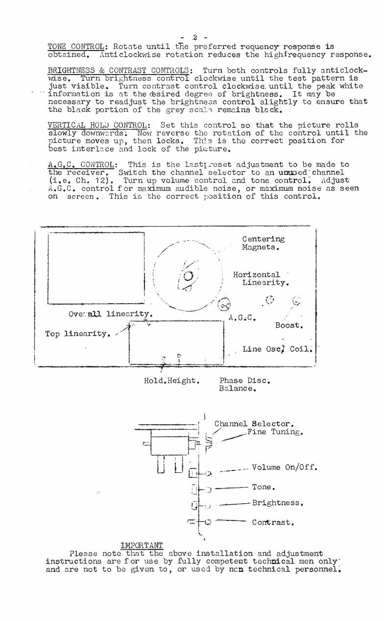
- .2 -TONE CONTROL: Rotnte until the preferredr-equency' response is obtnined. Anticlockwise rotation reduces the highfrequency response.
BRIGHTNESS & CONTRAST CONTROLS: Turn both controls fully anticlockvase. Turn brightness control clockwise until the test pattern is just visible. Turn contrnst control clockwise. until the peak white information is at the ffisired degree of brightness. It m~y be necessary to readjust the brightne3s control slightly to ensure that the black portion of the grey scnl'j remains black~
VERTICAL HOLD CONTROL: Set this control so that the picture rolls slowly downvr::.rds ~ Novr reverse the rotation of the control until the picture moves up, then locks. Th5.s is the correct position for best interl~ce and lock of the pi~ture.
A.G.C. CONTROL: This is the lastI.l.~eset adjustment to be made to the receiver. Switch ~he channel selector to an uouocd" channel (i.e. Ch. 12)~ Turn up volume control and tone control: Adjust A.G.C. control for maximum audible noise, or maximum noise as seen on screen. This is the correct position of this control.
1
I I I
i t'. ~
\
Centering Mngnets.
Horizontal Linearity.
~ "\
,/"'0 " "'~'~ \ :J,.'
Ove~_' aU linearity. ~~;l>.', ________ . A.G.C. ,..... t.; Boost.
Top linearity. /
Line Osc] Coil~ '7 C', I ___________________ ~====~~~="~·==~=;~~I~· ________ ~--------- . ... , ~
J
Hold.Height.
. i
Phase Disc. Balance •
------1 Channel ~elect0l':'"
.J G;~ \/ _____ Fwe Tumng.
1 ~~ p '--.-, -r-f -, -"-1 ~ I U _, Llt<> -------- Volume On/Off.
IMPORTANT
; : .)--- Tone.
f~ ., , .J '.J
__ -----Brightness.
Contrast.
Please note that the above installation and adjustment instructions are f or us e by fully competent technical men only' and are not to be given to, or used by ncn technical personnel~
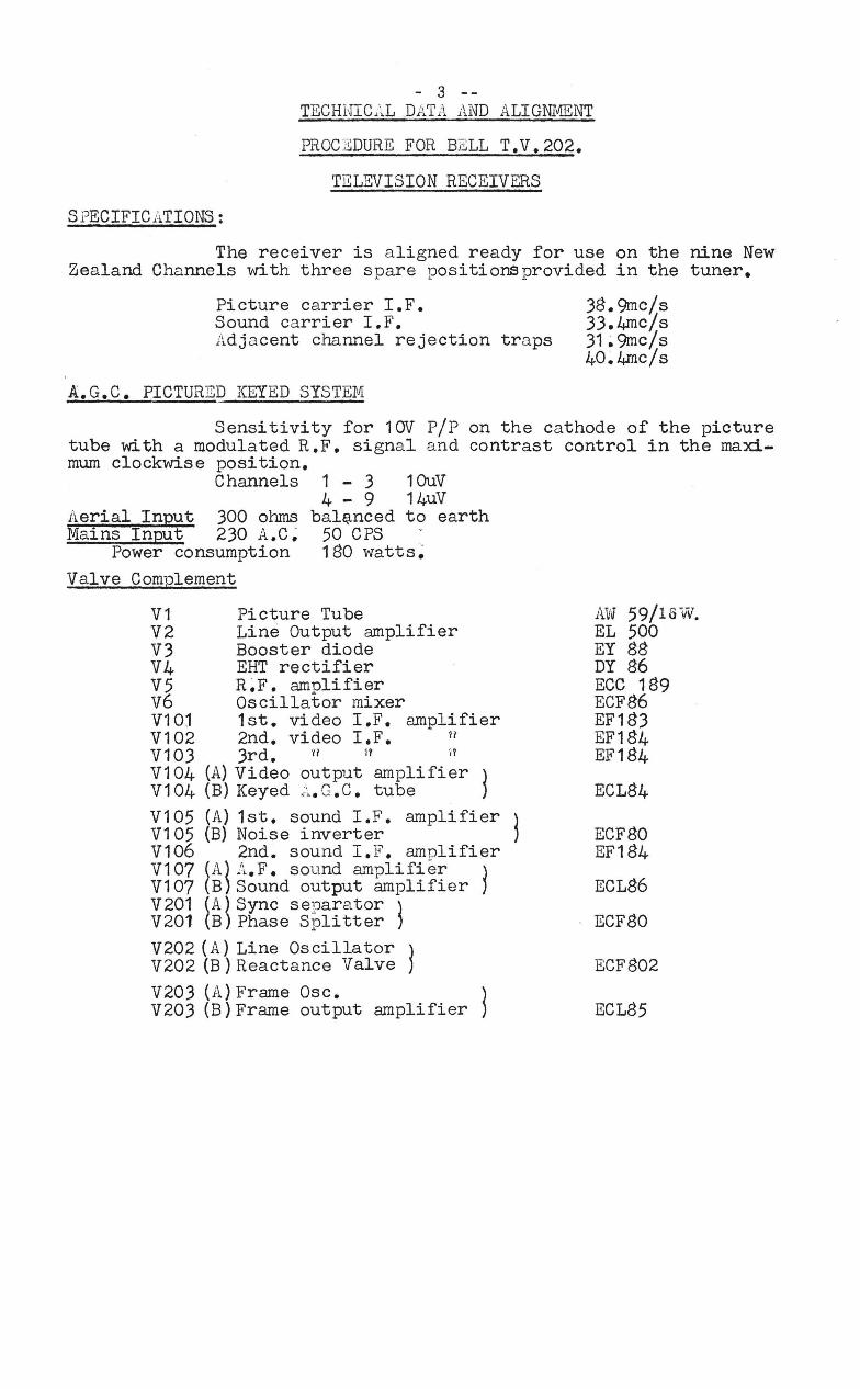
- 3 --TECHIUC.\L DATA AND ALIGNIJIENT
PROC EDURE FOR BELL T.V.202.
TELEVISION RECEIVERS
SPECIFICATIONS:
The receiver is aligned ready for use on the nine New Zealand Channels with three spare positions provided in the tuner.
Picture carrier I.F. Sound carrier I.F. Adjacent channel rejection traps
A.G.C. PICTURED KEYED SYSTEM
38.9mc/s 33.4mc/.s 31~9mc/.s 40.4mc/s
Sensitivity for 10V pip tube with a modulated R.F. signal and
on the cathode of the picture contrast control in the maxi-
mum clockwise position. Channels
Aerial Input 300 ohmS Mains Input 230 A.C~
Power consumption Valve Complement
1 - 3 4 - 9
bal(tnced 50 CPS
10uV 14uV to earth
180 watts~
V1 Picture Tube V2 Line Output amplifier V3 Booster diode V4 EHT rectifier V5 R~F. amplifier v6 Oscillator mixer V10j 1st. video I.F. amplifier V102 2nd. video I.F. 1/
V103 3rd. '11 11 IV
V104 (A) Video ~utput amplifier ) V104 (B) Keyed .-•• G.C. tube ) V105 (A) 1st. sound I.F. amplifier} V105 (B) Noise inverter ) V106 2nd. sound I.F. amplifier V107 (A) A.F. sound amplifier ) V107 (B) Sound output amplifier ) V201 (A) Sync separator } V201 (B) Phase Spli tter ) V202 (A) Line Oscillator ) V202 (B) Reactance Valve ) V203 (A) Frame Osc. ) V203 (B) Frame output amplifier )
AW 59/16W. EL 500 EY 88 DY 86 ECC 189 ECF86 EF183 EF184 EF184
ECL84
ECF80 EF184
ECL86
ECF80
ECF802
ECL85

TUNER
GENER.i~L DESCRIIDTION OF RECEIVER
- 4 -
The tuner on this receiver is a Philips AT7638/20 turret type using a double trio de (ECC189) as a cascode R;F. amplifier, with a triode pentode(ECF86) as the mixer oscillator. Low impedance coupling is used between the tuner and the vision I.F. amplifier so that the effect of strong interference signals will be minimised.
VISION I.F.
The three stage video I.F. ~~plifier uses an EF183 as the first valve which has a large value cathode resistor to give sufficient D.C. feedback to stabilise the voltage between the grid and cathode with alight variations of voltages and components in the A.G.C. circuit~ An '\.lnbypassed 22 ohm resistor is included in the first video I.F. amplifier cathode circuit to reduce the effect of A.G.C. variations on the input capacitance of this valve. For small signal conditions an OA85 Diode X101 is used to clamp the tun8~/voltage until the input sig-nal reaches 1~M.V. aGC
VIDEO DETECTOR AND )JJIPLIFIER
The video detector - an OA70 germanium diode - passes the ' composite video Signal to the grid of the video amplifier and a 5~5 MC/s trap circuit L102,C116 is provided in the cathode of the video amplifier (ECL$4). The contrast control is located in the plate circuit of the video amplifier (ECL84) valve, which ensures that the sync. signal amplitude is inde:)endant of contrast control setting.
Althou.gh the contrast control varies the peak to peak value of the signal, tt-e black level at the picture tube is kept substantially constant due fo the fact that the D.C. voltage at the H~T. side of the p~tentiometer is equal to the black level of the signal. The signal from the video amplifier valve is D.C. coupled to the cathode of the picture tube~
The brightness control alters the D.C. voltage on the first grid of the picture tube between 17 and 104 volts. A series combination of a V.D.R. resistor and a .47 mfd condenser is connected between g1 of the picture tube and ground to suppress the spot when switching the receiver off. SOUND CHANNEL
The 5~5 MC/s sound signal is taken off from the video detector and passed to the grid of the first sound I.F. amplifier via T106. The sound I.F. amplifier circuit, using two valves V105 and v106 amplifies the 5.5 MC/s F.M. sound signal and feeds it to the discriminator unit T108. The demodulated audio signal is amplified by the triode section of V1071\ then passed to the grid of V107B
After amplification by V107B the signal is passed through the output transformer T1 to the loudspeaker. A~M~ suppression is obtained by an amplitude modulation neg:ltive feedback circuit from g2 of the second sound I.F. amplifier to g1 of V1 05A~
." Additional suppression is obtained by a diode 1:imiter in the
anode circuit of v106. The amplification of the sound I.F. is controlled by an A.G.C. voltage derived from the discriminator and fed to g1 of V1 05A~
SYNC SEPARATION
The sync separator is the pentode section of an ECF80 (V201A); The composite video signal is applied to the grid of V201A via a long time constant Network (C123.R201) and D.C. restored at the grid of V201A by grid current. The valve V201A has a short grid base and therefore as the composite video signal voltage is much larger than the grid base the valve is only able to conduct during the synchronising pulses. Noise pulse~ ext~nding.above ~he amplitude of the syhchronising pulses on the compos1te.v1deo s1gnal.W1ll pro~uce'exces$ive grid currant 1n V201A, thereby charg1ng the coup11ng capac1tor
i'C123• The resultant
negative grid potential ho~ds V2g1A cut off, unti , the charge has leaked. away th:ough the gr1d res1stor R201. The synchronising pulses follow1ng a nQ1se pulse are therefore not produced in the anode circut

of V201 .A 5 -
NOISE INVERTER: Inverted noise pulses can be added to the composite video signal at the grid of the sync separator V201 A to reduce the effects of noise on the synchronising of the receiver and prevent blocking. The noise invertertriode V105B has the composite video signal applied to its grid, but is normally non conducting due to the positive cathode bias voltage. Noise pulses exceeding the amp~ litude of the video cause the valve to conduct producing amplified negative going pulse::; o.t its anode . R131, thererieo resistor to the separator valve grid! is us ed aE t he a node load rea.is tor for the noise inverter, and 'line noise pul se is therefore effectively cancelled at the control grid of the sync Eeparator valve.
LINE PHASE DISCRIMINATOR: The lil'e phase discriminator conSists of two BA100 diodes, x 202 and x203 and a triode pho.se splitter V201B which is used to provide anti phase pulses to the discriminator. A sawtooth waveform with fast flyba ck is derived from the negative pulses on the auxiliary winding of the line output transformer by the integrating network R212, C210, C209. The mean level of the sawtooth waveform at the junction of the diodeslaries according to the point on the flyback of the mwtooth at vfhich the gating pulses occur on the diodes. The resultant D.C. 1)otential is then fed via R213 to the control grid of the reactance valve, V202A which in turn controls the frequency of the line os cillator valve V202B ~ LINE OSCILLATOR & REACTANCE TUBE: V202B functions as a modified series connected 71HARTLEY'rY os cillator v.,rhich is electron coupled to the ~ILine Output!! stage. C213 is the tuning capacitor (connected via C230,R215 and V202B) and this condenser has V202A in parallel with it. The current through L201 lags the voltage by 900 • Consequently the current through R217 (150E) is lagging the voltage mcross the coil. The voltage produced across R217 is fed via a 220k pf condenser to the common cathode connection. The voltage on the~een end of L201 is always 1800 out of phase with the grid end (which is connected to the plate of V202A). Since the plate of V202A is delayed 1800 and'the cathode only 900 this tube exhibits a reactive characteristic, the degree of which is determined by the D.C. voltage on the grid of V202A~ A change in this voltage therefore produces a corresponding change in frequency of the line oscillator. LINE OUT PUT STAGE: Horizontal width is adjusted by R 18 which adjusts the reference current through the V.D.R. R17. The voltage developed across R 17 then sets the vmrking point for the grid of the line output valve V2 and as R17 acts as a rectifier for large asymetrical signals the voltage across R17 is inversely proportional to the current in the line output trans former. Using this circuit a 11 OC~ mains volt~ge variation results in only 1.97~ variation of E.H.T. and a 1.25% variation of the line deflection current.
FRAME TIMEBASE AND A]VIPLIFIER: The frame sync puIs es are taken from the anode of the sync separator and separated from the line pulses by a t'VITO stage integrator K201. After the integrator a diode clipper. is ins erted in the c ircui t to remove any residual line and or noise pulses. The frnme oscillator V203 A & B isa multivibrator, synchronised by negative going pulses to V203B grid. The plate supply for V203A is derived from the Boost voltage and R222 is included in this circuit to stabilise the voltage at the anode of V203A. The sawtooth voltage from C222 is shaped by R230 and C221 and applied to the grid of V203B which has negative feedback applied from the anode to the grid via C226 and R231. The frame output transformer has a VDR across the primary winding to stabilise the frame height which could otherwise vary with HT variations due to mains voltage flucuations. This VDR also clips high amnlitude transients which could otherwise exceed the insulation bre~down voltage of the transformer. A. G. C. In this system of generating an A.G.C. control voltage, the trio de section of V104B (ECL84) is used as a D.C. amplifier. A flyback pttlse from the line output transformer is applied across a VDR (R31), & the negative voltc.~9 so developed is conneeted,thrcogh the voltage dividing chain (R30j the A.G.C. control R29,R28,&R27) to the boost voltage line.

6 The anode of V104B is connected to a t apping on this chain.
The voltage on this tapping is de pendent upon the internal resistance of 'V104B. A positive voltage is a pplied to the cathode of this valve, and the "v alve will conduct whenthegrid voltage (video signal plus D.C. voltage from the anode of the video amplifier) rises above a certain level. Vari ations of the average anode voltage of V104B will cause variations of the voltage on the slider of the A.G.C. potentiometer, so creating the A.G.C. control voltage. The control voltage for the tuner is obtained by a voltage divider between the negative voltage supply VDR (131) & the cathode of the first I.F. valve.
POHER SUPPLY:- The H.T.'supply of 212V. is produced in a full - 'qve voltage doubling network, using silicon diodes x1 & x2, & C14, C15~ A 6.E5 ohm resistor is used to limit current surges througd the diodes. A separate C.R.T. heat er winding is used and the " balance of the heaters supplied by a centre t apped 12.6 volt winding.
SERVICING PRINTED BOARDS: - V/hen soldering, solder no thicker than 18 S.vtG. should be used, and in no circumst2nces should separate acid or greasy fluxes be applied. Avoid excessive heat and solder on joints; overhea ting can cause the copper laminate to lift. If necessary, flux residue can be r emoved with methyiliated spirit. When replacing peaking coils, care should be taken in bending the leads, as it is possible to break the thin litz wire.
When aligning , care should betaken not to lose a slug at the bottom of its travel. Although an unlikely event, it can be rectified by drilling a $mall hole in the boa rd directly under the slug and pushing it up with a stiff wire, or by removing the " transformer. The l atter method is to be avoided if possible.

t-
SYNC H. BOllR.D PRINThD SIDE.
()
," - --~ f) {
,-- - j
t (?) I - - - •• 1
tep Lin~ i Overall Lin.
,,-- .......
I V203. \
I ECLG5
\ / -- -
- . ..;
6·3rv
o
Y~r
--, /V201 ~" \
I , , ECF80 ,
\ I ..... 0 ,.,
plh 2 Sjnc in~
/' -/1[202. "
I \ l ECF80 I
\ / '-
OILine output tube grid~
BfReactance grid shorting point to adjust line osc. coil~
Frame l :Iold. r --, •
t • ; e · ..... - . Line OBe coil slug otherl side~ 0
' 1 ~--q 1 • 0. .. Frmn
l
, , b.P.T. ~ ' ~ \ Cl 0 fLine ~lyback. HT'1 . 0 0 Llne nybac shortlng
• .' • Pha:l.e disc oint to adjust phase balance pot. chscrir:d.natmr
Boost HT. HT.+3

EDAC :lF~ Board Component side. Ht~ ,. . .. Cl
AGe. o D
Enrth
I.F. input
O " ~ ' ® F sa V101
a ~~k m. O I B1'1S3
00
.6-3 '\I 1" D
Volume cont~oll 0 end.
Jut~ut trans~ I a
~Qrth I 0
1 01umo control I Cl slider
J.T. '('1 D
H.T.+4 a
'S9 S10' Orra"Js 0 ...
Sound detector o S~ S~
1311 31J °2nd IFT~
~
o
lEd ;~u~~]
8,14 'Sf5
~d IF~..! ~ ~
S17 s16 o 0 Q Video detector
.S~~t'· 0 oup..d .
:S~e soundlOl tpap L::.J
(] P a Sllder
o IBrilliance
-. .' AGe.
o I~avhode pict~ tube:
Contrast control

ALIGNMENT INSTRUCTIONS FOR THE
BELL T. V. 2C2. FRAME GRID VISION 1. F.
Equipment Required:
VISION ALIGNMENT
Oscilloscope. Sweep Generator Marker Generator. Bias Voltage Supply.
Use 68 K resistor and. 47 400 volt condensor in series with & amplifier lead for all measurement s. During alignment keep generator output at minimum necessary to give accurate results.
Connect 6 V bias across C. 103 with positive lead to pin 9 of V. 101 Connect oscilloscope Y amplifiers lead to C. R. T. cathode lead Turn contrast control to maximum Set tuner to an unused channel Connect the output lead from the sweep generator to pin 2 of V. 103. Set sweep generator to sweep over the 1. F. band then tune S 16 and S. 17 to give response as shown in fig 1. Change the sweep generator lead from pin 2 of V. 103 to pin 2 of V. 102., ar:d tune S. 14 and S. 15 to give response as shown on fig 2. Next inject the sweep generator signal into the grid of V. 101 through C. 10l. Tune S. 13 for a minimum at 33.4 and tune S. 12 and S. 11 for response as shown in fig 3. Change sweep generator lead from C. 101 and connect to M2 on tuner. Tune S. 9 for dip at 31. 9mc/ sand S. 10 lor dip at 40~ 4 mc. s. Next tune S. 7 S 8 and tunet 1. F. to give response as shown in fig, 4. This completesthevision 1. F. alignment.
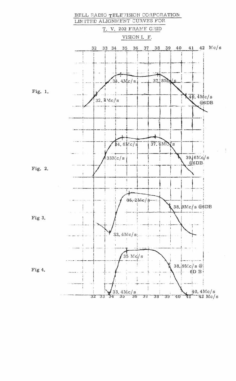
Fig. 1.
Fig. 2.
Fig 3.
Fig 4.
BELL S ADIe TELF7ISION CORPORATION LIlV ITED ALIGNMENT CURVES FOH
T. V. 202 FRAl\fE G 8.ID
VISION 1. F.
.__ 32 33 34 35 36 37 38 g9 40 ',' -r \ I --r-~; ; j-
t ' i , , . I 1 ! It i ~ i I I i ; 1 ~
, .. , .. I" , t "-r--·-t--i·-";-<=: ,-I-.! . L ' I I .f"" ""iIr---l---+--~
.' : --.- j-- -., 1st
'" '-.. , ~ .. " ' - " , ~ " '" .. ,f ., ... ---t---i1r--==-l---r----+
, 32. a ''vle!s i I I _ • I ,' .. -'-··1--t-r-'-!--
I : , I'
41 42 Me/ s
--to.
~ t --~~~--~r-~---4---+---+---+---+--~--~--. <
I! I t ,1 ': ---i--+----t-··.,.. .. -·---~·~- .. ·!.I -1-I i 1 ; ; 1
4~6rc/r--fw.1Mcl s -I-.T.',,-,-: ,33Me/s r" - II~' -it-, , , I I
, r-, :
-7 ~ ---~ -+-. _. r .- '-r--' ...... , , I i I I ! 1 _ _
~----+-- .. ~ ____ t ! t I , t : , I ' I -- r- - --I - ~---
i ~
r .,. ;
.. ... . .. ,L .. __ ',_ ...
' - - . - , i " , f "
·1 --, I
I ' . 1 ~ , -- ... ... ---t--t---+--.-- .~ -
",· 1 .. 1. . I !
~2~1r--'~ --1 -r-1--! 1 I 1 38.!9Me! s @$DB
... :...--- ... !. ; :. , I
,-+_. , .. ".-- --~- .-j I !
-. : . . - ~ . . -~ ••. - .- i - ,
I I
. -.~. --.-.. --... -~- .-. ~ ". -.J..--..;.---t-_
35 Mc/s ! .. ~_._ .. _+._. . i
!
. ,- . .. ...,. -- ~
-r" ~'. " ~-7-

SOUND I. F. ALIGNMENT.
Connect bias of 4. 5 volts between junction of R 138, R 147 with positive lead to chassis.
Connect scope lead to anode of V 105A dia diode probe as shown in figure 5.
OA 85 j- I - I /,- --, - -I : I ---~,,--
/ ; '. " IK :' IK 47 K \
Anode V:.cl05~_ n l-l __ l_"" \/V \;'\ __ 'l'-"' __ ' _'\/\ /' ': ._ I >l" - ' , I . . ; ~
Scopt e.
Earth 1 100 pf :
~ ..... ---------..... !--iUIJ _~-,I
Fig 5.
Where possible use 5. 5 mc/ s crystal otherwise set sweep generator to 5. 5 mc/ s and connect to sound take off coil (junction of R 121, L102 and C125)
Tune SI and S2 for maximum response at 5. 5 mc/ s
Response should be as shown in figure En.
Change scope lead from anode of VI05a to anode of V 106
Adjust S3 and 84 for maximum gain and symetrical response as shown in figure 7.
\ ( \ ) ~/ Fig. 6.
5. 5mc/ s
Fig 7.
Remove diode probe from oscilloscope and connect oscilloscope to output of sound idscriminator i. e. C. 134
Adjust S 6 to give 5. 5 mc/ s in centre of cur v ; and adjust S 5 for maximum response.
Required waveform is as shown in fugure 8.
Connect scope tl"ia diode probe to anode of V 104A and tune L 102 for maximum dip. .- ,
/ /

Note:
TUNER DATA and ALIGNMENT
PROCEDURE.
Re alignment of the tuner is not normally necessary and shoukl only be attempted if the tuner has been repaired.
When aligning the R. F. circuits" the parts of the response curve" between the visition and sound markers should be as flat as possible. The response curve is shown is figure 9.
With the fine tuping control set to the rrp-ldle of its range" the receiver oscillator should be adjusted to the oscillator frequencies set out below:
CHANNEL VISION CARRIER. SOUND CARRIER. OSCILLATOR.
1 45.25 50.75 84.15 2 55.25 60.75 94.15 3 62.25 67.75 101. 15 4 175.25 180.75 214.15 5 182. 25 187.75 221. 15 6 189.25 194.75 228. 15 7 196/25 201.75 235.15 8 203.25 208.75 242.15 9. 210.25 215. 75 249. 15
The gain of the tuner i s 10 times when the output of the tuner is loaded with a IK resistance.
With the tuner A. G. C. v~ltage set to 0 volts the oscillator anode voltage is 130 volts and the current is 10 m. 8. The B. F. valve anode is 180 volts and the current is 25 m. a.
----. _ .. - ... -. --_. __ ._ .... _. --_ ....... _-...... -... __ . -.... _" .. " _ ... _.-.. _ .. ---7--
.~ // 15%
PICTURE. SOUND.
FIG 9.
R. F. ALIG NMENT of the Tuner.
Connect oscillhscope to Ml and apply the R. F. sweep signal to the aerial terminals.
1. Damp the aerial circuits SI .. S.2, S3, with a 390 ohm resistor. 2. Switch tuner to channel 3. 3 Adjust CI0 and C15 for as good a band pass cur~e as possible. 4. Switch tuner to channel 9. 5. Adjust the coils S10 and SII fo r as good a band pass curve as possible. 6. Repeat steps 2, 3" 4 and 5, 7. Remove the damping resistor and switch to channel 3. 8. Adjust C8 for as good a band pass curve as possible.

F
r-________ 820p:t:
I I ~~ I -.L. I 82Opf_' - -
I IM ...--IVtA/''----.--
I 1 ( :re 12.7P~ ECC 1:0~ l~ '"'~'1~~ I _t~-t(06?~,l-:.L_i ~ 3pf .
I!Pf. ~. I ~ ___ L~ I J "g, S18A fM 1 I I 1_
I((; "~ -- -1 () ~
t }. section .. ~I 300 J'\. aerial B C
-==:---.
l! 8~f _
M J
.' ;:;: j
211' c/
-R.F. test point
~ --I
I 820PfT
7.5K
~"-~L--,.......I..-...,...-.....,
1.5pf
- --