lead electrical engineer - flp.co.za · “cathodic protection from a hazardous viewpoint ” olof...
TRANSCRIPT

“CATHODIC PROTECTION FROM A HAZARDOUS VIEWPOINT ”
Olof Bekker Pr. Eng. BSc. Eng. BML S.MSAIEE, M.NACE Lead Electrical Engineer

“CATHODIC PROTECTION FROM A HAZARDOUS VIEWPOINT”
Cathodic Protection is the “Electrical” method of c ontrolling and stopping the rust process of underground/submerged steel pipelines and structures.
INTRODUCTION
� Involvement in cathodic protection and hazardous area classification. � Influence of cathodic protection on hazardous areas and selection of
equipment for safe use therein’ � Misunderstood and neglected technologies. � Maintenance and monitoring intensive. � Deterioration and breakage of essential components such as bonds,
grounding cells, etc. � AC mitigation and associated hazards. � The need to understand the basics of cathodic protection. INVOLVEMENT IN CATHODIC PROTECTION & HAZARDOUS AREA CLASSIFICATION The author has been intimately involved for the past 19 odd years, in all aspects pertaining to cathodic protection as well as in the classification of hazardous areas and the selection of electrical equipment for safe use therein in the petrochemical industry. It is from this basis that I wish to transpose some information regarding the influence of cathodic protection on hazardous areas in the petrochemical industry. It is therefore from this basis that I wish to transpose some information regarding the influences of cathodic protection on hazardous areas in places where there is a presence of hydrocarbons. INFLUENCE OF CATHODIC PROTECTION ON HAZARDOUS AREAS & SELECTION OF EQUIPMENT FOR SAFE USE THEREIN The industry either totally ignores the need for cathodic protection or proceeds with the best of intentions and spend a great deal of time and money in the design and installation of cathodic protection systems but do not maintain the system as per acceptable engineering and legislative standards.

Until quite recently not much attention was paid to the possible influence that cathodic protection could have in hazardous areas as the art was not fully understood and thus the implications ignored. We will examine the effect that cathodic protection and the systems coupled to it have on and in hazardous areas in more detail in the paper.
MISUNDERSTOOD & NEGLECTED TECHNOLOGIES
Cathodic protection of underground steel pipes, tank bottoms and structures is one of the most misunderstood and as a result one of the most neglected engineering technologies in the industry today. This is especially true for the petrochemical industry. In fact some people do not believe it actually works and it has been referred to as some or other “black” art whereas it is fact state of the art technology covering a number of disciplines.
MAINTENANCE & MONITORING INTENSIVE
Unfortunately cathodic protection systems are to a certain extent maintenance intensive as a result of the “battery effect” i.e. the anode, cathode, electrolyte and subsequent current flow. It is this lack of maintenance and monitoring of the system that leads or could lead to a hazardous situation. Unfortunately cathodic protection systems are to a certain extent maintenance intensive as a result of the “battery effect” i.e. the anode, cathode, electrolyte and subsequent current flow. One of the reasons for this lack of maintenance is that once the system is installed it is no longer “visible” being predominantly underground.
DETERIORATION & BREAKAGE OF ESSENTIAL COMPONENTS SU CH AS BONDS, GROUNDING CELLS, ETC
Deterioration and breakage of essential components such as bonds, grounding cells, insulating flanges, isolating joints and anodes could cause an uneven impressed current distribution and this coupled to a situation where the underground steel structure under protection is inadvertently grounded to above grade steel structures, results in a spark. If the spark is of such magnitude in the presence of a gas, vapour or liquid there will be an explosion and a fire.

AC MITIGATION AND ASSOCIATED HAZARDS
Another area of concern is the mitigation of AC voltages transmitted from overhead power lines and lightning into underground steel pipelines. Magnetic induction acts along the pipeline segment that is approximately parallel to the power line and can cause significant pipeline potentials even at relatively large separation distances. This is not only detrimental to the pipe integrity but is a hazard to persons coming into contact with above ground portions of the pipe such as valves. These exposed structures can be a potential shock hazard when touched while the soil is at a significantly different potential. Added to this is the hazard that in most cases these pipes transport hydrocarbons and should a spark be generated the resultant fire and explosion could occur.
THE NEED TO UNDERSTAND THE BASICS OF CATHODIC PROTE CTION
• To understand the concerns one must understand the basics of Cathodic Protection.
• To function, the system requires 3 inputs, namely an Anode, a Cathode and the Electrolyte. In most instances the use of Impressed current is the preferred method in our industry.
• The Anode is either a precious metal Oxide (Titanium coated) Anode or a Centrifugally Cast Silicon Iron tube,
• the Cathode is the buried steel pipe, structure or tank bottom • And the Electrolyte is the soil. • The power source is in the form of a Transformer Rectifier Unit that
typically has the ability to put out 50 volts DC and 100 amps or more.

IMPRESSED CURRENT SYSTEM
ANODE GROUNDBED
� The application of an external DC current through long-lasting anodes. � � Typical source of power, AC power converted to DC by a modulated
rectifier. � � Groundbeds are connected to the power by a positive cable to the power
source. � � A negative cable connects the power source to the structure. � � The path being the electrolyte is the soil.
+
TRU
----
IMPRESSED CURRENT
D.C. CURRENT
BURIED STEEL PIPELINE

STATIC – FORMATION OF CHARGES AT HIGH VOLTAGES
“Q”
� Charge (Q) exchange occurs between 2 surfaces that are (V) low voltage
in very intimate contact with each other i.e. flanges.
� The maximum voltage between 2 such surfaces is ±1 volt or less. This is
process dependent.
� At this low voltage the surfaces from condensor / capacitor (C).
� Thus Q = C x V.
� Now when the 2 surfaces are separated, capacity (C) is highly reduced.
There is virtually no charge leakage thus (Q) remains constant. Therefore
(V) must and does increase dramatically to high values causing sparks.
� This situation is worse where an insulating flange is inserted, as the
potential difference across the flange could be greater. This is why it is
imperative to fit a polarisation cell across the flange.
C
V Q = C x V
Flange
Pip
Q = C x V =”SPARK”

TYPICAL SCENARIO
A number of incidents of “sparks” were reported in a petrochemical plant and
the “Sparks”, were thought to be the cause of a fire in one of the units. At the
time of the fire there was a hydrocarbon leak and it was only due to expedient
action by one of the personnel that averted a major disaster.
On top of this there were incidents reported of personnel receiving electrical
shocks on containing metallic structures, especially during the operation of
breaking product line flanges.
The major concern surrounding the sparks was the likelihood of explosions
and fires with the associated disastrous results of damage to equipment, loss
of production and injury to personnel or loss of life.
What aggravated the situation was that these Sparks were observed during
the upgrading of the cathodic protection systems and the technical information
as to the amount of impressed current being pumped into the ground being in
the region of 1000 amps was misconstrued.
The Production personnel assumed occurrence of sparks to be caused by
cathodic protection as they were of the opinion that the 100 amps was
concentrated and did not understand or realize that this current was in fact
distributed via many parallel paths to all the underground steel pipes and tank
bottoms which in fact meant that the current at any given point was
theoretically very low.
Instruction was given to isolate the cathodic protection supplies pending an
investigation and resolution.
This exercise to rectify took six months at considerable cost. (Figure 1 –
Isolation of underground structures)

One of the implications was that there was no protection on the underground
steel structures and this in itself was a hazard as there could have been
corrosion and leaks.
For Cathodic protection to be effective it must be isolated from aboveground
steel (earthed) structures. In the event that the underground steel structures
are bonded to aboveground steel structures which in turn are connected to
the plant earth then the subsequent drain of impressed cathodic current
renders the system ineffective and could cause sparks.
Isolation takes the form of coatings, wrapping, insulating flanges, isolating
joints, etc.
From the investigation it transpired that a large number of the steel structures
had been bonded and/or connected and these consisted of the following:-
• Oily water sewers with aboveground pipes welded to them,
• Vents on oily water sewers which not wrapped/coated,
• Exposed steel on firewater mains pipes where isolation joints rise
above ground,
• Emergency showers bonded to underground potable water lines,
• Exposed steel grating on sewers,
• Earthed domestic water lines- no isolation joints/insulating flanges,
(SANS 101042 Part 1 – The wiring of premises)

FIGURE 1- ISOLATION OF UNDERGROUND STEEL STRUCTURES
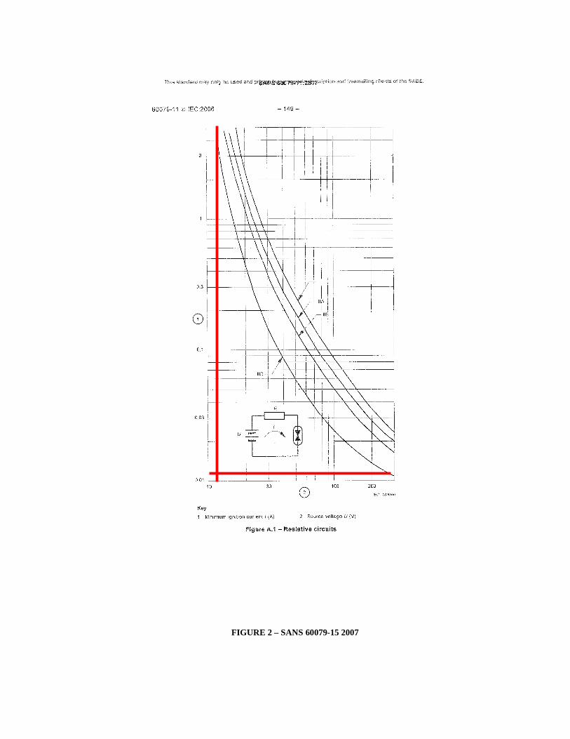
FIGURE 2 – SANS 60079-15 2007

SANS 60079-15 2007 We refer to the chart above to ascertain the incendive values in a purely resistive circuit typically found in cathodic protection systems, which in the worst case scenario, would be in the presence of Hydrogen at a voltage of 15 volts and 5 amps. This determines whether a spark has sufficient energy to ignite a gas, vapour or liquid in an area where there is a likelihood of the presence of a hydrocarbon. Needless to say all tests confirmed that there is no danger as the maximum values obtained were in the region of 0.5 volts and 100 milliamps. We also attempted to draw a spark from the system by bonding the underground structure and earthing this to above grade structures. Despite several attempts at worst case we failed to draw a spark and in fact could not even see a spark!
CONCLUSION
The fact remains that there are inherent dangers related to cathodic protection in a
petrochemical industry.
Specifications and standards such as SANS 10108, SANS 10121, SANS 10123, SANS
101089, CP 1021 reference to the inherent dangers associated with cathodic protection
installations in hazardous areas such as petrochemical plants.
Preventative measures to ensure no hazard from sparking and electrical shock to
personnel:
• Isolation of underground/aboveground metallic pipes, structures and tank bottoms.
• Earthing and grounding of structures.
• Switching off cathodic protection systems prior to working.
• Placing jumpers across insulating flanges prior to breaking the flange.
• Isolating / insulating structures from interference currents.
• Solid state isolating devices such as “Rustol” cathodic isolators.
• Grounding/polarising cells across insulating flanges/isolating joints.
RECOMMENDATIONS
In view of the fact that there are certain hazards such as:
• Resultant “sparks” that cathodically protected structures could generate when
underground metallic structures are shorted to aboveground earthed metallic
structures.
• When an insulating flange is broken and the resultant charge generated causes a
spark in the presence of hydrocarbons.
• AC mitigation, stray currents, etc.

“It is highly recommended that all reasonably practical measures are taken to avoid these
hazards and that the systems are maintained in a good working order and monitored.
Ensure that grounding/polarisation cells, cathodic isolators, as applicable, are installed
over insulating flanges and maintained.
ACKNOWLEDGEMENTS
I hereby wish to express my thanks to Fluor and SAFA for allowing me the opportunity to publish and present this paper.
I also wish to thank and give credit to all those in the industry who have kindly allowed me
the use of some of this information and for the many years assistance and dedication.
The information contained in this paper is based on many years experience and exposure
of the author, in the field of cathodic protection and hazardous area design, installation
and maintenance, as well as the review and study of technical publications and other
writers. While the statements purpose to be accurate, each reader is responsible for their
own interpretation.