le1 operator manual - motorvac · contaminants from gasoline engines. the le-1 is a self-contained...
TRANSCRIPT

MV P/N 100-8135 Rev C 1998
CARBONCLEAN
MODEL LE-1 CARBONCLEAN SYSTEM II
OPERATORS MANUAL
MOTORVAC TECHNOLOGIES

1998 MotorVac Technologies, i
Table of Contents Introduction ...........................................................................................................................................ii Overview ...............................................................................................................................................iv System Features and Functions...................................................................................................... 1-1
Control Panel Features and Functions......................................................................................... 1-2 Safety Information............................................................................................................................. 2-1 Before You Begin .............................................................................................................................. 3-1
First Time Operation..................................................................................................................... 3-1 Mixing Ratios ................................................................................................................................ 3-2
Fuel System Cleaning Procedures.................................................................................................. 4-1 Determining the Vehicle's Fuel System Type............................................................................... 4-1 Carburetor Setup Procedure ........................................................................................................ 4-3 Carburetor Cleaning Procedure.................................................................................................... 4-5 Throttle Body Injection (TBI) Setup Procedure............................................................................. 4-7 Throttle Body Injection (TBI) Cleaning Procedure...................................................................... 4-10 Port Fuel Injection (PFI) Setup Procedure ................................................................................. 4-12 Port Fuel Injection (PFI) Cleaning Procedure............................................................................. 4-15 Continuous Injection System (CIS) Setup Procedure ................................................................ 4-17 Continuous Injection System (CIS) Cleaning Procedure ........................................................... 4-20
Vehicle Diagnostics .......................................................................................................................... 5-1 Fuel System Pressure Test .......................................................................................................... 5-2
Troubleshooting and Additional Help............................................................................................. 6-1 Appendix A - Maintenance ...............................................................................................................A-1
Maintenance Procedures..............................................................................................................A-1 Replacing the LE-1 Fuel Filter ......................................................................................................A-1 Maintenance Record ....................................................................................................................A-2
Appendix B - System Accessories..................................................................................................B-1 Standard Adaptor Kit ....................................................................................................................B-1 Deluxe Adaptor Kit........................................................................................................................B-3
Appendix C - Parts ............................................................................................................................C-1 External Parts for the LE-1 ...........................................................................................................C-1
Appendix D - MATERIAL SAFETY DATA SHEET...........................................................................D-1 Material Safety Data Sheet...........................................................................................................D-1

1998 MotorVac Technologies, ii
Introduction
Congratulations on your selection of the CARBONCLEAN SYSTEM II. By choosing this product, you are acquiring the most technologically advanced method available for cleaning harmful fuel system contaminants from gasoline engines. The LE-1 is a self-contained cleaning system, designed to connect to any gasoline engine. Once the unit is connected, it temporarily replaces the regular fuel supply with a mixture of gasoline and the specially formulated CarbonClean Cleaning Detergent for Gasoline. With the engine idling, the unit pumps the gasoline/detergent mixture through the engine's fuel system. As the mixture passes through the vehicles’ fuel system, it loosens and dissolves accumulated deposits, which then pass harmlessly out through the exhaust system or are removed by the unit fuel filter. Removing contaminants from the combustion chamber creates a more even burn of fuel, which improves horsepower, increases fuel economy, and reduces exhaust emissions. It is recommended that you perform the fuel system cleaning procedure on a vehicle every 12,000 to 16,000 kilometers to obtain the highest fuel system efficiency. Please study this User Guide to become thoroughly familiar with the LE-1 before using it.
IMPORTANT
The LE-1 Fuel System Cleaner is designed to work EXCLUSIVELY
with the CarbonClean Cleaning Detergents for Gasoline.
Use of any other chemical during this process may cause operational failure of the LE-1 and voids the manufacturer’s warranty.
See warranty card for details.

Introduction
1998 MotorVac Technologies, iii
Notes:

1998 MotorVac Technologies, iv
Overview This manual contains all the information you need to use the LE-1. Please make sure all technicians using the unit read this manual and have it within easy reach whenever the unit is being used. The following is a quick reference to the information in this manual: System Features and Functions
This chapter describes the LE-1 gauge, control switches, and connections. Safety Information
Adhere to the safety guidelines in this chapter at all times!
Before You Begin
Follow the instructions in this chapter before using the unit for the first time. Fuel System Cleaning Procedures
This chapter contains step-by-step setup and cleaning procedures for using the unit with each of the four fuel system types: Carburetor, Throttle Body Injection (TBI), Port Fuel Injection (PFI), and Continuous Injection System (CIS).
Vehicle Diagnostics
This chapter describes how to use the unit to perform system tests on the vehicle in order to rule out other fuel system-related problems.
Troubleshooting and Additional Help
Turn to this chapter in the unlikely event you have problems with your LE-1 or need additional help.
Appendices - Maintenance, Accessories, and Parts
The appendices contain routine maintenance procedures for the LE-1, such as changing the fuel filter, lists of available accessories and replacement parts, and the Material Safety Data Sheets.

Overview
1998 MotorVac Technologies, v
Notes:

Overview
1998 MotorVac Technologies, vi
System Features and Functions The front of the LE-1 cabinet contains the control panel, control switches and status indicators. The fuel reservior and filter are mounted on the rear of the cabinet.
ALARM
GAUGE
PRESSURE REGULATOR
OUTPUT HOSE red
RUN CYCLE
POWER ‘ON’ INCICATOR
POWER SWITCH
START-RUN SWITCH
TIMER
RETURN HOSE black
BATTERY LEADS
ADAPTER STORAGE DRAWER
FLUID TANK

Overview
1998 MotorVac Technologies, vii
LE-1 Features and Functions Descriptions of the gauge, control switches, and status indicators that make up the control panel are listed below. Please become familiar with these control panel features and functions before using the unit. Adjust Time Knob Sets or re-sets the system run time in one-minute increments, from 1
to 60 minutes.
Start/Run Switch Starts the cleaning cycle.
Run Cycle Light Illuminates when the run cycle is under way.
Fuel Pressure Gauge Displays output pressure of the unit’s output hose, or system pressure of the vehicle being serviced.
Pressure Adjust Regulator
Used to adjust the system pressure during the cleaning process. Turn clockwise to close (increase the pressure); counterclockwise to open (decrease the pressure).
Warning Alarm Sounds when the run cycle is complete or when a pressure loss occurs.
Power Switch Shuts off power to the unit.
Output Hose (red) Connects to the input side of the vehicle's engine fuel system.
Return Hose (black) Connects to the return side of the vehicle's engine fuel system.
Fuel Filter Filters out contaminants that become removed during the cleaning process. See Appendix A for replacement information
Battery Cables Positive (red) and negative (black) battery connections (11-15 VOLTS DC)

Overview
1998 MotorVac Technologies, viii
Safety Information and Precautions
/!\ DANGER Vehicle exhaust gases contain Carbon Monoxide, which is a colorless and odorless lethal gas. Only run engines in well-ventilated areas and avoid breathing exhaust gases. Extended breathing of exhaust gases will cause serious injury or death.
/!\ WARNING
Exhaust gases, moving parts, hot surfaces, and potent chemicals are present during the use of the fuel system cleaner. Read and understand the operator’s manual before using the fuel system cleaner. When using chemicals always refer to the MSDS sheets and manufacturer’s instructions for the proper procedure to handle emergency medical treatment, cleanup, handling, and storage requirements. Improper use of the fuel system cleaner or exposure to exhaust gases or cleaning chemicals can cause injury. Flammable fuel chemical and vapors can ignite. Avoid exposure to flames, sparks, hot engine parts, and other ignition sources. Always keep fully charge fire extinguisher nearby. The extinguisher should have a class B rating and be suitable for gasoline, chemical, and electrical fires. Cleanup any fuel or chemical spills immediately. Dispose of contaminated cleanup material according to governing environmental laws. Never look directly into the air induction plenum or carburetor throat when the engine is operating. Always plug or cap any open fuel lines during service. Keep Cleaner and Detergent container closed except when filling reservoir. Explosion or flame or exposure to flammable liquid and vapors can cause injury. Flammable liquid can splash out of reservoir when pump is on and/or unit is being moved. Always keep Reservoir Cap secure except when filling reservoir. Explosion or flame can cause injury. Many fuel systems maintain residual pressure in fuel lines even after the engine has been turned off. Wear safety goggles. Wear chemical resistant gloves when connecting or disconnecting fitting and adaptors. Obtain ZERO psi before connecting or disconnecting any fuel lines or adaptors. Explosion or flame or exposure to flammable liquid and vapors can cause injury.

Overview
1998 MotorVac Technologies, ix
Chemicals can cause harmful byproducts. Use only approved chemicals (refer to operator’s manual). Do not swallow or ingest any chemicals. Use with adequate ventilation. Avoid breathing vapors. Do not store chemicals on the machine. Improper use of chemicals can cause injury. Over exposure can have harmful effect on eyes, skin, respiratory system and possible unconsciousness and asphyxiation. Improperly blocked vehicles can move. Set the parking brake and chock the wheels. Moving vehicles can cause injury. Moving engine parts. The engine cooling fan will cycle on and off depending on the coolant temperature and could operate without the engine running. Wear safety goggles. Always keep objects, clothing, and hands away from the cooling fans and engine parts. Moving engine parts can cause injury. Hot surfaces are present during and after running the engine. Do not contact hot surfaces such as, manifolds, pipes, mufflers, catalytic converters, or radiators and hoses. Hot surfaces can cause injury. Catalytic converters become extremely hot. Do not park a converter-equipped vehicle over dry grass, leaves, paper, or any other flammable material. Do not touch a catalytic converter until the engine has been off for at least 45 minutes. For tests allowing unburned hydrocarbons or service involving operation of an overly rich condition, minimize the time of rich operation, monitor the catalytic converter temperature, and allow at least two minutes of operation at normal mixture subsequent to testing or service for converter cooling. Catalytic converters can cause burns. Cracked fan blade can become airborne. Examine fan blades for cracks. If found, do not service the vehicle. Flying objects can cause injury. Batteries produce explosive gases and can explode. Wear safety goggles when working on or near batteries. Use in a well-ventilated area. Keep sparks and flames away from the battery and never lay tools, equipment, or other conductive objects on the battery.

Overview
1998 MotorVac Technologies, x
When tools or equipment is connected to the battery, make sure the equipment power switch is off. Connect the positive lead of the equipment to the positive lead battery first; connect the negative lead of the equipment to a solid ground point as far from the battery as possible. Keep battery acid away from skin or eyes. In case of eye contact, flush with clean water for 15 minutes and get medical attention. Battery explosion and ignited gases can cause injury.

Overview
1998 MotorVac Technologies, xi
Before You Begin First Time Operation
NOTE
The following process is used to flush factory testing fluids out of your new machine, and is only necessary before the first time you use the unit.
1. Verify that the LE-1’s fuel filter is connected and securely in place in the rear of the cabinet. 2. Check the output/return hoses, battery connections, and all external components for damage. 3. Turn the Pressure Adjust regulator on the unit control panel counterclockwise until it is
completely open. 4. Attach the unit to the vehicle's battery by connecting the red battery clip to the positive (+)
battery terminal and the black battery clip to a solid ground point as far from the battery as possible. Turn on the LE-1 power switch.
5. Fill the LE-1’s reservoir with clean gasoline until the tank level indicates 1/4 tank.
6. Connect the LE-1’s output (red) hose and return (black) hose together by using the #060-1400 adaptors and securing them with a clamp. Follow the procedures below to flush fuel
through the system: • Set the Timer knob for five minutes. • Press and hold the Start/Run switch for five minutes. • Release the Start/Run switch.
7. Disconnect the output and return lines. 8. Connect the #060-1400 adaptor to the output hose, then drain the gasoline from the LE-1’s
reservoir using the following procedure:
• Set the Timer knob for five minutes. • Direct the output (red) hose into an appropriate container. • Press and hold the Start/Run switch until the fuel from the unit has been emptied into the
container.

Overview
1998 MotorVac Technologies, xii
• Release the Start/Run switch. • Dispose of the fuel in an environmentally approved method.
9. The LE-1’s reservoir is now completely drained of fuel. Follow the steps below before
performing the first cleaning service:
Mixing Ratios Using a separate container or the LE-1’s reservoir, follow the chart below to mix the proper amounts of CarbonClean Cleaning Detergent for Gasoline and fuel for the cleaning process.
NOTE The proper ratio is 1 oz. (30 ml.) per cylinder to 3 oz. (90 ml.) gasoline.
DETERGENT / GASOLINE RATIO 3 cylinders = 3 oz. (90 ml.) detergent to 9 oz. (270 ml.) gasoline, (360 TOTAL) 4 cylinders = 4 oz. (120 ml.) detergent to 12 oz. (360 ml.) gasoline, (480 TOTAL) 5 cylinders = 5 oz. (150 ml.) detergent to 15 oz. (450 ml.) gasoline, (600 TOTAL) 6 cylinders = 6 oz. (180 ml.) detergent to 18 oz. (540 ml.) gasoline, (720 TOTAL) 8 cylinders = 8 oz. (240 ml.) detergent to 24 oz. (720 ml.) gasoline, (960 TOTAL) 10 cylinders = 10 oz. (300 ml.) detergent to 30 oz. (900 ml.) gasoline, (1200 TOTAL) 12 cylinders = 12 oz. (360 ml.) detergent to 36 oz. (1080 ml.) gasoline, (1440 TOTAL)

Overview
1998 MotorVac Technologies, xiii
Fuel System Cleaning Procedures
Determining the Vehicle's Fuel System Type
It is very important to determine the fuel system type of the vehicle to be serviced before performing any setup or cleaning procedure on the vehicle. The unit can be used with any of the four different types of fuel systems listed below:
Carburetion
Carburetors come in a variety of sizes and shapes. These can be easily identified by
locating the choke plate in the air horn.
Throttle Body Injection (TBI) Throttle bodies are centrally mounted, as are carburetors, and use one or two electronic
injectors.
Port Fuel Injection (PFI) This system uses a single electronic injector per cylinder, mounted so that fuel spray is
directed into the intake port.
Continuous Injection System (CIS) A Continuous Injection System is easily identified by noting the fuel distributor and the
solid steel or flex steel lines running from the fuel distributor to each individual injector. The fuel distributor controls the amount of fuel sprayed into the intake port while the injectors control the opening and closing pressure.
NOTE
Once you have determined the fuel system type, turn to the appropriate section in this chapter for instructions on how to perform the fuel line setup and cleaning procedure for that system.

Overview
1998 MotorVac Technologies, xiv
Notes:

Overview
1998 MotorVac Technologies, xv
Carburetor Setup Procedure Follow the steps below to connect the unit to the vehicle's fuel system. Make sure the vehicle has at least 1/8 tank of fuel before beginning this process.
1. Start the vehicle and allow the engine to reach normal operating temperature.
IMPORTANT
Do not perform the setup or cleaning process if the vehicle’s
engine oil or coolant level is low. If necessary, add oil and/or coolant to the vehicle.
2. Turn the vehicle OFF when normal operating temperature has been reached. 3. Turn the Pressure Adjust regulator counterclockwise until the regulator is completely
open. Verify that the LE-1’s power is switch is turned off. 4. Attach the unit to the vehicle's battery by connecting the red battery clip to the positive (+)
battery terminal and the black battery clip to a solid ground point as far from the battery as possible. Turn on the LE-1 power switch.
5. Remove the vehicle's gas cap to relieve fuel tank pressure. 6. Verify that the engine is no longer running. 7. Disconnect the vehicle’s fuel line at the carburetor inlet or at the fuel pump outlet. There
should now be two open ends to work with:
• One coming from the fuel pump. • One going into the carburetor.
8. Add gasoline and detergent mixture to the LE-1 reservoir. When filling the reservoir of the LE-1, add 1 oz. (30 ml.) per cylinder of Detergent to 3 oz. (90 ml.) gasoline. (Refer to page 3-2 for the proper ratios.)

Overview
1998 MotorVac Technologies, xvi
/!\ WARNING
Flammable Liquid can squirt out of pressurized lines when connecting or disconnecting. Wear Safety goggles. Obtain ZERO pressure before connecting or disconnecting any fuel lines or adaptors. Wear chemical resistant gloves when connecting or disconnecting fittings and adaptors. Wrap shop towel around pressure fittings and adaptors when disconnecting. Avoid exposure to flames, sparks, hot engine parts, and other ignition sources. Explosion or flame or exposure to flammable liquid and vapors can cause injury.
9. As shown in the figure on the below, connect the LE-1’s output (red) hose to the inlet of the
carburetor and block the fuel line coming from the vehicle’s fuel pump.
You are now ready to perform the carburetor cleaning procedure.

Overview
1998 MotorVac Technologies, xvii
Carburetor Cleaning Procedure Follow the steps below to circulate the fuel/detergent mixture through the vehicle's carburetor. 1. Verify that Carburetor Setup Steps 1- 9 above have been completed.
2. Refer to the vehicle's service manual for the manufacturer's recommended PSI.
3. Adjust Timer knob for 30 minutes. (Run time may be adjusted depending on the condition of the
vehicle’s fuel system.) 4. Press and hold the Start/Run switch. 5. Turn the Pressure Adjust regulator clockwise until the Fuel Pressure gauge reads 4 PSI, or the
equivalent of the manufacturer's recommended specifications. 6. Release the Start/Run switch. Check all connections for leaks. 7. Start the vehicle to begin the fuel system cleaning process.
• When the cleaning process is halfway completed, step on the vehicle’s accelerator quickly
three or four times. Then, maintain RPM at 1500 - 2000 for 30 seconds.
8. When the run time expires, the cleaning is complete. The unit will automatically shut off and the LE-1’s alarm will sound.
9. Turn OFF the vehicle's engine. 10. Turn the Pressure Adjust regulator counterclockwise on the unit to release any residual
pressure.
IMPORTANT Wrap a shop towel around pressure fittings before disconnection to protect against residual fuel spray.
11. Disconnect the battery leads, hoses, and adaptors. Return the vehicle's fuel system to its normal
operating condition by re-connecting the vehicle's fuel lines. 12. Re-install the vehicle's gas cap.
13. Start the vehicle and verify that there are no leaks.

Overview
1998 MotorVac Technologies, xviii
14. Test drive the vehicle for five kilometers immediately following the cleaning service to flush all
detergent from the vehicle's fuel and exhaust systems.

Overview
1998 MotorVac Technologies, xix
Throttle Body Injection (TBI) Setup Procedure Follow the steps below to connect the unit to the vehicle's fuel system. Make sure the vehicle has at least 1/8 tank of fuel before beginning this process.
1. Start the vehicle and allow the engine to reach normal operating temperature.
IMPORTANT
Do not perform the setup or cleaning process if the vehicle’s
engine oil or coolant level is low. If necessary, add oil and/or coolant to the vehicle.
2. Turn the vehicle OFF when normal operating temperature has been reached. 3. Turn the Pressure Adjust regulator counterclockwise until the regulator is completely open. Verify that the LE-1’s power switch is turned off. 4. Attach the unit to the vehicle's battery by connecting the red battery clip to the positive (+)
battery terminal and the black battery clip to a solid ground point as far from the battery as possible. Turn on the LE-1 power switch.
5. Remove the vehicle's gas cap to relieve fuel tank pressure. 6. Verify that the engine is no longer running. 7. Disconnect the vehicle’s fuel lines from the throttle body. There are now four open ends to
work with:
Pressure Line Return Line
From the tank to the throttle From the throttle body to
8. Add gasoline and detergent mixture to the LE-1 reservoir. When filling the reservoir of the
LE-1, add 1 oz. (30 ml.) per cylinder of Detergent to 3 oz. (90 ml.) gasoline. (Refer to page 3-2 for the proper ratios.)

Overview
1998 MotorVac Technologies, xx
/!\ WARNING
Flammable Liquid can squirt out of pressurized lines when connecting or disconnecting. Wear Safety goggles. Obtain ZERO pressure before connecting or disconnecting any fuel lines or adaptors. Wear chemical resistant gloves when connecting or disconnecting fittings and adaptors. Wrap shop towel around pressure fittings and adaptors when disconnecting. Avoid exposure to flames, sparks, hot engine parts, and other ignition sources. Explosion or flame or exposure to flammable liquid and vapors can cause injury.
9. As shown in the figure below, connect one end of the loop adaptor (#060-2501) to the pressure line coming from the vehicle's fuel tank. Connect the other end of the loop adaptor (#060-2501) to the return line going back to the fuel tank. This forms a tank-to-tank loop, making it unnecessary to disconnect the fuel pump.
10. As shown in the figure above, connect the output (red) hose from the unit to the adaptor on the
pressure line going into the TBI unit. 11. As shown in the figure on the previous page, connect the return (black) hose from the unit to the
adaptor on the return line coming from the TBI unit.
You are now ready to perform the TBI cleaning procedure.

Overview
1998 MotorVac Technologies, xxi
Throttle Body Injection (TBI) Cleaning Procedure
Follow these steps to circulate the cleaning mixture through the TBI unit to clean the throttle body, injector screens, and pressure regulator.
1. Verify that TBI Setup Steps 1-11 above have been completed before continuing. 2. Refer to the vehicle's service manual for the manufacturer's recommended PSI. 3. Adjust Time for 10 minutes. 4. Press and hold the Start/Run switch. 5. Turn the Pressure Adjust regulator clockwise until closed. This will clean the TBI unit and filter the particles through the LE-1’s filtering system.
6. Release the Start/Run switch. Check all connections for leaks.
• Make a note of the fuel pressure reading; this is the true opening pressure of the vehicle’s pressure regulator without vacuum assist when the engine is at normal operating
temperature.
• NOTE: By turning the Pressure Adjust regulator in and out and “PULSING” the mixture from time to time, the cleaning process will be enhanced in this mode.
7. After the 10 minutes has expired adjust Timer knob for an additional 30 minutes. (Run time may
be adjusted depending on the condition of the vehicle’s fuel system.) 8. Press the Start/Run switch. 9. Start the vehicle to begin the fuel system cleaning process. 10. When the run time expires, the cleaning is complete. The unit will automatically shut off and the
LE-1’s alarm will sound. 11. Turn OFF the vehicle's ignition. 12. Turn the Pressure Adjust regulator counterclockwise on the unit to open it and release residual
pressure.

Overview
1998 MotorVac Technologies, xxii
IMPORTANT Wrap a shop towel around pressure fittings before disconnection to protect against residual fuel spray.
13. Disconnect the battery leads, hoses, and adaptors. Return the vehicle's fuel system to its normal
operating condition by re-connecting the vehicle's fuel lines. 14. Re-install the vehicle's gas cap. 15. Start the vehicle and verify that there are no leaks. 16. Test drive the vehicle for five kilometers immediately following the cleaning service to flush all
detergent from the vehicle's fuel and exhaust systems.

Overview
1998 MotorVac Technologies, xxiii
Port Fuel Injection (PFI) Setup Procedure
Follow the steps below to connect the unit to the vehicle's fuel system. Make sure the vehicle has at least 1/8 tank of fuel before beginning this process.
1. Start the vehicle and allow the engine to reach normal operating temperature.
IMPORTANT
Do not perform the setup or cleaning process if the vehicle’s
engine oil or coolant level is low. If necessary, add oil and/or coolant to the vehicle.
2. Turn the vehicle OFF when normal operating temperature has been reached. 3. Turn the Pressure Adjust regulator counterclockwise until the regulator is completely open. Verify that the LE-1’s power switch is turned off. 4. Attach the unit to the vehicle's battery by connecting the red battery clip to the positive (+)
battery terminal and the black battery clip to a solid ground point as far from the battery as possible. Turn on the LE-1 power switch.
5. Remove the vehicle's gas cap to relieve fuel tank pressure. 6. Verify that the engine is no longer running. 7. Disconnect the vehicle’s fuel lines from the fuel rail. There are now four open ends to work with:
Pressure Line Return Line From the fuel tank to the fuel rail. From the fuel rail to the fuel tank.
8. Add gasoline and detergent mixture to the LE-1 reservoir. When filling the reservoir of the LE-1,
add 1 oz. (30 ml.) per cylinder of Detergent to 3 oz. (90 ml.) gasoline. (Refer to page 3-2 for the proper ratios.)

Overview
1998 MotorVac Technologies, xxiv
9. As shown in the figure below, connect one end of the loop adaptor (#060-2501) to the pressure line coming from the vehicle's fuel tank. Connect the other end of the loop adaptor (#060-2501) to the return line going back to the fuel tank. This forms a tank-to-tank loop, making it unnecessary to disconnect the fuel pump.
10. As shown in the figure above, connect the output (red) hose from the unit to the adaptor on the pressure line going into the fuel rail.
11. As shown on the previous page, connect the return (black) hose from the unit to the adaptor on the return line coming from the fuel rail.
You are now ready to perform the PFI cleaning procedure.

Overview
1998 MotorVac Technologies, xxv
Port Fuel Injection (PFI) Cleaning Procedure
Follow these steps to circulate the cleaning mixture through the Port Fuel Injection unit to clean the fuel rail, injector screens, and pressure regulator. 1. Verify that PFI Setup Steps 1-11 above have been completed before continuing. 2. Refer to the vehicle's service manual for the manufacturer's recommended PSI. 3. Adjust Time until it displays 10 minutes. 4. Press and hold the Start/Run switch. 5. Turn the Pressure Adjust regulator clockwise until the gauge displays 4 PSI. The pump will
remain on. 6. Release the Start/Run switch and continue to turn the Pressure Adjust regulator clockwise until
it is completely closed. This will clean the PFI unit, injector screens, fuel rail, and pressure regulator and filter the contaminants through the LE-1’s filtering system. Check all connections for leaks.
• Make a note of the fuel pressure reading; this is the true opening pressure of the vehicle's pressure
regulator without vacuum assist when the engine is at normal operating temperature. • NOTE: By turning the Pressure Adjust regulator in and out and “PULSING” the mixture from
time to time, the cleaning process will be enchanced in this mode. 7. After the 10 minutes has expired, adjust Time to 30 minutes. (Run time may be adjusted
depending on the condition of the vehicle’s fuel system.) 8. Press the Start/Run switch. 9. Start the vehicle to begin the fuel system cleaning process. 10. When the run time expires, the cleaning is complete. The unit will automatically shut off and the
LE-1’s alarm will sound. 11. Turn OFF the vehicle's ignition. 12. Turn the Pressure Adjust regulator counterclockwise on the unit to release any residual
pressure.

Overview
1998 MotorVac Technologies, xxvi
IMPORTANT Wrap a shop towel around pressure fittings before disconnection to protect against residual fuel spray.
13. Disconnect the battery leads, hoses, and adaptors. Return the vehicle's fuel system to its normal
operating condition by re-connecting the vehicle's fuel lines. 14. Re-install the vehicle's gas cap. 15. Start the vehicle and verify that there are no leaks. 16. Test drive the vehicle for five kilometers immediately following the cleaning service to flush all
detergent from the vehicle's fuel and exhaust systems.

Overview
1998 MotorVac Technologies, xxvii
Continuous Injection System (CIS) Setup Procedure
Follow the steps below to connect the unit to the vehicle's fuel system. Make sure the vehicle has at least 1/8 tank of fuel before beginning this process.
1. Start the vehicle and allow the engine to reach normal operating temperature.
IMPORTANT
Do not perform the setup or cleaning process if the vehicle’s
engine oil or coolant level is low. If necessary, add oil and/or coolant to the vehicle.
2. Turn the vehicle OFF when normal operating temperature has been reached. 3. Turn the Pressure Adjust regulator counterclockwise until the regulator is completely open. Verify that the LE-1’s power switch is turned off. 4. Attach the unit to the vehicle's battery by connecting the red battery clip to the positive (+)
battery terminal and the black battery clip to a solid ground point as far from the battery as possible. Turn on the LE-1 power switch.
5. Remove the vehicle's gas cap to relieve fuel tank pressure. 6. Verify that the engine is no longer running. 7. Disconnect the vehicle’s fuel lines from the fuel distributor. There are now four open ends to
work with:
Pressure Line Return Line From the fuel tank to the fuel distributor. From fuel distributor to the fuel tank.
8. Add a pre-mixed gasoline and detergent mixture to the LE-1 reservoir. When filling the reservoir
of the LE-1, add 1 oz. (30 ml.) per cylinder of Detergent to 3 oz. (90 ml.) gasoline. (Refer to page 3-2 for the proper ratios.)

Overview
1998 MotorVac Technologies, xxviii
9. As shown in the figure below, connect one end of the loop adaptor (#060-2501) to the pressure line coming from the vehicle's fuel tank. Connect the other end of the loop adaptor (#060-2501) to the return line going back to the fuel tank. This forms a tank-to-tank loop, making it unnecessary to disconnect the fuel pump.
10. As shown in the figure above, connect the output (red) hose from the unit to the adaptor on the
pressure line going into the fuel distributor. 11. As shown in the on the previous page, connect the return (black) hose from the unit to the
adaptor on the return line coming from the fuel distributor.
You are now ready to begin the CIS cleaning procedure.

Overview
1998 MotorVac Technologies, xxix
Continuous Injection System (CIS) Cleaning Procedure
Follow the steps below to circulate the cleaning mixture through the CIS fuel distributor to clean the pressure regulator and the top portion of the fuel distributor. 1. Verify that CIS Setup Steps 1-11 above have been completed before continuing. 2. Refer to the vehicle's service manual for the manufacturer's recommended PSI.
3. Adjust Time knob for 10 minutes. 4. Press and hold the Start/Run switch. 5. Turn the Pressure Adjust regulator clockwise until the gauge displays 4 PSI. The pump will
remain on. 6. Release the Start/Run switch and continue to turn the Pressure Adjust regulator clockwise until
it is completely closed. This will clean the CIS fuel distributor and filter particles through the LE-1’s filtering system. Check all connections for leaks.
• Make a note of the fuel pressure reading; this is the true opening pressure of the vehicle's
pressure regulator when the engine is at normal operating temperature.
• NOTE: By turning the Pressure Adjust regulator in and out “PULSING” the mixture from time to time, the cleaning process will be enhanced in this mode.
• If the “PULSING” is too great, it could stop the engine.
7. After the 10 minutes has expired, adjust time for 30 minutes. (Run time may be adjusted depending on the condition of the vehicle’s fuel system.)
8. Press the Start/Run switch. 9. Start the vehicle to begin the fuel system cleaning process.
• When the cleaning process is halfway completed, step on the vehicle’s accelerator quickly three or four times. Then, maintain RPM at 1500 - 2000 for 30 seconds.
• If the vehicle is equipped with a Cold Start Injector, you may use a Pulse Tester to energize
the Cold Start Injector a few quick times during the run cycle to clean it.
10. When the run time expires, the cleaning is complete. The unit will automatically shut off and the LE-1’s alarm will sound.

Overview
1998 MotorVac Technologies, xxx
11. DO NOT ALLOW CIS VEHICLES TO RUN OUT OF FUEL. TURN OFF THE VEHICLE’S ENGINE BEFORE COMPLETION OF THE RUN CYCLE.
12. Turn the Pressure Adjust regulator counterclockwise on the unit to release residual pressure.
IMPORTANT Wrap a shop towel around pressure fittings before disconnection to protect against residual fuel spray.
13. Disconnect the battery leads, hoses, and adaptors. Return the vehicle's fuel system to its normal
operating condition by re-connecting the vehicle's fuel lines. 14. Re-install the vehicle's gas cap. 15. Start the vehicle and verify that there are no leaks. 16. Test drive the vehicle for five kilometers immediately following the cleaning service to flush all
detergent from the vehicle's fuel and exhaust systems.

Overview
1998 MotorVac Technologies, xxxi
Vehicle Diagnostics Although vehicle diagnostic tests are not a mandatory part of the cleaning procedure, they can help determine if poor engine performance is caused by other conditions related to the fuel system. TBI Systems The following tests may be performed for this system:
• Fuel System Regulator Opening Pressure • Fuel System Regulator Running Pressure
PFI Systems The following tests may be performed for this system:
• Fuel System Regulator Opening Pressure • Fuel System Regulator Running Pressure
CIS Systems The following tests may be performed for this system:
• Fuel System Regulator Opening Pressure • Fuel System Regulator Running Pressure

Overview
1998 MotorVac Technologies, xxxii
Fuel System Pressure Test
1. Verify that Setup Steps 1-12 from the previous chapter have been completed for the specific fuel system type to be tested.
2. Note the vehicle’s fuel system pressure reading from the Fuel Pressure gauge on the control
panel of the unit after starting the cleaning process. • Check vehicle’s pressure regulator’s opening pressure. Check the manufacturers specifications
for the correct specification. • Check the vehicle’s running pressure. Check the manufacturers specifications for the correct
specification. 4. Return to the previous chapter, Fuel System Cleaning Procedures, to continue the cleaning
process. Otherwise, conclude the test as described below. 5. Turn the vehicle off.
IMPORTANT Wrap a shop towel around pressure fittings before disconnection
to protect against residual fuel spray.
6. Disconnect the battery leads, hoses, and adaptors. Return the vehicle fuel system to its normal
operating condition by re-connecting the vehicle fuel lines.

Overview
1998 MotorVac Technologies, xxxiii
Troubleshooting and Additional Help Refer to the list below in the unlikely event that you have problems with your LE-1. Problem: Solution: 1. Power Light is ON and the LE-1 is not
operational.
Polarity is reversed on vehicle battery connection. Check connections for correct polarity. Check FUSE on the front panel
2. Pressure Gauge on the LE-1 displays maximum pressure upon start up.
Output and Return hoses may be reversed. Turn Timer to zero and check hoses for correct connection.
3. Rapid loss of fuel from the LE-1 reservoir.
Return hose connection may be incorrect, allowing fuel/detergent to return to the vehicle's fuel tank.
4. Start/Run switch is on but operation does not commence.
Check Run/Time. If no time is set, then turn the Time knob to set the run time.
5. The LE-1 performs poorly.
Check all hoses and wires for cuts or frays. Check cabinet for dents or impact markings. Verify that the fuel filter has recently been replaced. (Refer to the maintenance log in Appendix A to view dates of services performed.)
ADDITIONAL HELP
Please verify that items 1-5 above have been reviewed before calling for additional assistance. In the unlikely event that problems persist with the LE-1, call:
MotorVac Technologies
At (714) 549-8810

Overview
1998 MotorVac Technologies, xxxiv
Appendix A - Maintenance Maintenance Procedures The following maintenance procedures should be performed on a routine basis: 1. Drain the unit’s fuel reservoir and replace the fuel filter after every 30 cleaning services, as
described in the next section. 2. Clean the exterior with a non-abrasive cleaning agent or similar product to keep the cabinet
looking new. Check the cabinet for dents or impact markings. 3. Check all hoses and wires for cuts or frays. Replacing the LE-1 Fuel Filter The unit’s fuel reservoir should be drained and the fuel filter replaced after every 30 cleanings to ensure maximum system performance and pump life.
Drain the Fuel Reservoir 1. Turn the Pressure Adjust regulator on the control panel clockwise until it is completely closed. 2. Attach the unit to the vehicle's battery by connecting the red battery clip to the positive (+)
battery terminal and the black battery clip to a solid ground point as far from the battery as possible. Turn on the LE-1 power switch.
3. Connect the #060-1400 adaptor to the output (red) hose, then drain the gasoline from the unit’s
fuel reservoir using the following procedure:
• Set the Time until it displays five minutes. • Direct the output (red) hose into an appropriate container. • Press and hold the Start/Run switch until the fuel from the unit has been emptied into the
container. • Release the Start/Run switch. • Turn the Pressure Adjust Regulator counterclockwise until completely open to relieve any
residual pressure. 4. Enter your initials, the date, and a check mark in the appropriate boxes of the Maintenance
Record at the end of this chapter.

Overview
1998 MotorVac Technologies, xxxv
Replace the Fuel Filter 1. Remove the old fuel filter from the mounting station on the back of the unit’s cabinet and install
the new filter. Verify correct direction of the arrow for fuel flow. 2. Tighten the clamps securely to prevent any spills. 3. Add the mixture back into the LE-1’s reservoir. 4. Check the filter for leaks. 5. Enter your initials, the date, and a check mark in the appropriate boxes of the Maintenance
Record at the end of this chapter. The unit is now ready for the next cleaning service. Maintenance Record Use the following table to keep a record of maintenance performed on the LE-1. Initial/Date
DRAIN FUEL RESERVOIR
REPLACE FUEL FILTER
CLEAN EXT. CABINET
CHECK HOSES AND WIRES
OTHER
/
/
/
/
/
/
/
/
/
/
/
/
/

Overview
1998 MotorVac Technologies, xxxvi
Initial/Date
DRAIN FUEL RESERVOIR
REPLACE FUEL FILTER
CLEAN EXT. CABINET
CHECK HOSES AND WIRES
OTHER
/
/
/
/
/
/
/
/
/
/
/
/
/
/
/
/
/
/
/
/
/
/
/
/
/
/
/

Overview
1998 MotorVac Technologies, xxxvii
Initial/Date
DRAIN FUEL RESERVOIR
REPLACE FUEL FILTER
CLEAN EXT. CABINET
CHECK HOSES AND WIRES
OTHER
/
/
/
/
/
/
/
/
/
/
/
/
/
/
/
/
/
/
/
/
/
/
/
/
/
/
/

Overview
1998 MotorVac Technologies, xxxviii
Appendix B - System Accessories Standard Adaptor Kit (200-8058) The standard adaptor kit is included with your LE - 1 system. The most commonly used application is listed; however, other applications may apply.
PART & NO. QTY APPLICATION
060-1400
2
GENERAL APPLICATIONS UTILIZING 5/16" FUEL LINE - FEMALE. (USE WITH SUITABLE HOSE CLAMPS )
060-1600
1
12MM BANJO FITTING CIS OR EFI SYSTEMS. IN CONJUNCTION WITH 060-1900, 060-1901, 060-1902.
080 1100
1
HOSE MENDER TUBE 5/16" - MALE. (USE WITH SUITABLE HOSE CLAMPS.)
060-1900 060-1901 060-
1 3 1
CONNECTS 12MM BANJO FITTINGS FOR DIAGNOSTICS AND/OR CREATING A LOOP.
060-2300
1
17MM WRENCH SIZE WITH 14MM THREADS - EUROPEAN CARS INLET AND/OR RETURN. MAY BE USED WITH 060 2700
060-2401
1
8MM BANJO FITTING EFI SYSTEMS OR COLD START INJECTOR. USE WITH 8MM DOUBLE BANJO BOLT (060 2710)
060 2402
1
14MM BANJO FITTING BMW AND LATE MODEL VW PRESSURE LINE.
060-2600
1
19MM WRENCH SIZE WITH 16MM THREADS - EUROPEAN CARS INLET AND/OR RETURN.

Overview
1998 MotorVac Technologies, xxxix
PART & NO. QTY APPLICATION
060-2700
2
14MM X 16MM UNION. USE IN CONJUNCTION WITH 060-2300 AND 060-2600 FOR CIS APPLICATIONS.
060-0440
5
HOSE CLAMP. (MEDIUM)
080-2301
1
HOSE MENDER STEM USE WITH 080-2300 AND 060-0440
080-2300
1
HOSE MENDER NUT USE WITH 080-2301 AND 060-0440
060-2501
1
FORMS "TANK TO TANK" LOOP ON ALL VEHICLES. USED TO EXTEND VEHICLE'S RETURN LINE DURING DIAGNOSTICS.
080-1600
1
HOSE MENDER BANJO (12MM) USE WITH 060-0440
080-2402
1
HOSE MENDER BANJO (14MM) USE WITH 060-0440
080-2600
1
HOSE MENDER NUT (16MM) USE WITH 060-0440
080-2601
1
HOSE MENDER STEM USE WITH 080-2600 AND 060-0440

Overview
1998 MotorVac Technologies, xl
Deluxe Adaptor Kit (200-8059) Contact your LE - 1 sales representative for information on obtaining the deluxe adaptor kit. The most commonly used application is listed; however, other applications may apply.
PART & NO. QTY APPLICATION
060-0450
1
HOSE CLAMP (LARGE)
060-1000
2
GENERAL APPLICATIONS UTILIZING 1/4" FUEL LINE - MALE. (USE WITH SUITABLE HOSE CLAMPS.)
060-1100
2
GENERAL APPLICATIONS UTILIZING 5/16" FUEL LINE- MALE. (USE WITH SUITABLE HOSE CLAMPS.)
060-1200
2
GENERAL APPLICATIONS UTILIZING 3/8" FUEL LINE - MALE. (USE WITH SUITABLE HOSE CLAMPS.)
060-1300
2
GENERAL APPLICATIONS UTILIZING 1/4" FUEL LINE - FEMALE. (USE WITH SUITABLE HOSE CLAMPS.)
060-1500
2
GENERAL APPLICATIONS UTILIZING 3/8" FUEL LINE - FEMALE. (USE WITH SUITABLE HOSE CLAMPS.)
060-1900 060-1901 060-1902
1 3 1
CONNECTS 12MM BANJO FITTINGS FOR DIAGNOSTICS AND/OR CREATING A LOOP.
Overview
1998 MotorVac Technologies, xli
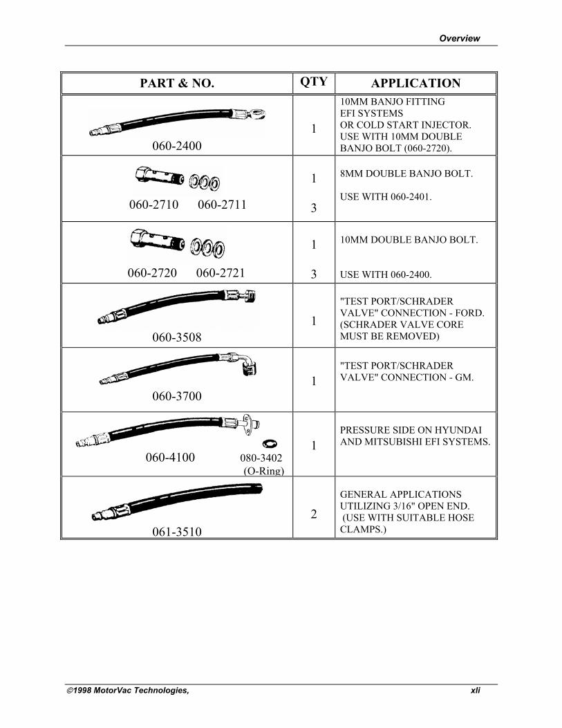
PART & NO. QTY APPLICATION
060-2400
1
10MM BANJO FITTING EFI SYSTEMS OR COLD START INJECTOR. USE WITH 10MM DOUBLE BANJO BOLT (060-2720).
060-2710 060-2711
1 3
8MM DOUBLE BANJO BOLT. USE WITH 060-2401.
060-2720 060-2721
1 3
10MM DOUBLE BANJO BOLT. USE WITH 060-2400.
060-3508
1
"TEST PORT/SCHRADER VALVE" CONNECTION - FORD. (SCHRADER VALVE CORE MUST BE REMOVED)
060-3700
1
"TEST PORT/SCHRADER VALVE" CONNECTION - GM.
060-4100 080-3402 (O-Ring)
1
PRESSURE SIDE ON HYUNDAI AND MITSUBISHI EFI SYSTEMS.
061-3510
2
GENERAL APPLICATIONS UTILIZING 3/16" OPEN END. (USE WITH SUITABLE HOSE CLAMPS.)

Overview
1998 MotorVac Technologies, xlii
Appendix C - Parts External Parts for the LE-1 Please refer to the part numbers below when ordering parts for the LE-1.
Part # Description
010-6060 Reservoir cap, Vented
020-8063 Harness, power
030-0020 Conn M. 3/8x 1/4 NPT NI
050-0071 Filter (In-line 3/8 Barb)
080-0230 Female Quick Disconnect Couplers
200-8052 Assy, Return hose (black)
200-8051 Assy, Output hose (red)
400-0020 CarbonClean Cleaning Detergent for Gasoline
400-0030 MotorVac4 Intake Cleaner (Optional)
200-8058 Standard Adaptor Kit
200-8059 Deluxe Adaptor Kit
200-6001 Intake System Kit (Optional)
020-0014 Front Panel Fuse
100-8135 LE-1 Operators Manual
ORDERING PARTS Parts for the LE-1 may be ordered by calling:
MotorVac Technologies at
714-549-8810