ld-oem laser measurement system -...
TRANSCRIPT
S U P P L E M E N T T O T H E
O P E R AT I N G I N S T R U C T I O N S
Description and Technical Data
of LD-LRS1000/2100/3100
LD-OEM
Laser Measurement System
Supplement to the Operating Instructions
LD-OEM Laser Measurement System
2 © SICK AG · Division Auto Ident · Germany · All rights reserved 9106698/0000/2006-03-06
Software Versions
Described software versions
Differences from LD-LRS1000/2100/3100 to LD-OEM
(overview)
Copyright
Copyright © 2006
SICK AG Waldkirch
Auto Ident, Reute Plant
Nimburger Strasse 11
79276 Reute
Germany
Trademarks
Windows 98SETM, Windows NTTM, Windows 2000TM and Windows XPTM are registered trade-
marks or trademarks of the Microsoft Corporation in the USA and other countries.
Latest manual version
For the latest version of this manual (PDF), see www.sick.com.
Software/Tool Function Version
LD-LRSxx00 Firmware V 2.1.8
LD-LRSxx00
device description
Device-specific software module for SOPAS from V 1.0
SOPAS SICK Open Portal for Application and Systems Engineering Tool.
Configuration software for LD-LRSxx00
V 2.08
No. Feature See page
1 Modified scanner head 5, 22
2 Higher enclosure rating (IP 67 housing for LD-LRS2100/3100) 5, 22
3 Smaller tolerance of supply voltage 5, 22
4 Lower max. scanning frequency 5, 22
5 Supplement: Maximum current consumption of the switching outputs 5
6 LD-LRS1000: New signal names of the 6-pin terminal strip 7
7 LD-LRS1000: New pin assignment of the 15-pin D-Sub HD plug 7
8 LD-LRS2100/3100: new plug connection (20-pin Harting insert) 8
9 LD-LRS1000: Switch for data interface RS 232/RS 422 6
10 LD-LRS1000: Switch for CAN bus termination 6
11 New: SOPAS Configuration software 18, 20
12 New: Ethernet interface 14, 20
13 Reduced max. cable length for CAN interface 22
14 Modified technical data 22
15 New dimensional drawings 24
16 New accessories 26
17 No longer available: Arcnet interface –

Supplement to the OIs
LD-OEM
Contents
9106698/0000/2006-03-06 © SICK AG · Division Auto Ident · Germany · All rights reserved 3
Contents
1 Differences from LD-LRSxx00 to LD-OEM ............................................................... 5
1.1 Device variants......................................................................................................... 5
1.2 Operating voltage..................................................................................................... 5
1.3 Pin assignment ........................................................................................................ 6
1.3.1 Pin assignment LD-LRS1000 ............................................................................ 6
1.3.2 Pin assignment LD-LRS2100/3100 ................................................................. 8
1.3.3 Pre-fabricated cables for RS 232/RS 422/CAN ............................................10
1.3.4 Ethernet interface ............................................................................................13
1.4 Mounting ................................................................................................................17
1.4.1 Selecting the installation location...................................................................17
1.4.2 Mounting the LD-LRS2100/3100...................................................................17
1.5 Quick start with default settings by factory..........................................................18
1.5.1 Quick start using the RS 232/RS 422 data interface ...................................18
1.5.2 Quick start using the Ethernet interface (10 Mbit/s) ....................................20
1.6 Technical data........................................................................................................22
1.7 Dimensional drawings ...........................................................................................24
1.7.1 LD-LRS1000 .....................................................................................................24
1.7.2 LD-LRS2100/3100..........................................................................................25
1.8 Accessories ............................................................................................................26
2 EC Declaration of Conformity ..................................................................................27
2.1 Fulfillment of the EU Machine Guidelines............................................................27
2.1.1 EC Declaration of Conformity ..........................................................................27
Note From this point on, the Long Range Scanner and all its variants will simply be referred to as
“LD-LRSxx00“ (unless a distinction is required).
The LD-LRS2100/3100 is exclusively intended for use in an industrial environment.
In case of use in residential areas, RF interference may occur.

Supplement to the Operating Instructions
LD-OEM Laser Measurement System
4 © SICK AG · Division Auto Ident · Germany · All rights reserved 9106698/0000/2006-03-06
Contents
Tables
Table 1-1: LD-LRSxx00 variants .......................................................................................... 5
Table 1-2: Max. current consumption of the switching outputs ....................................... 5
Table 1-3: LD-LRS1000 interface adapter: Default settings ............................................ 6
Table 1-4: LD-LRS1000 interface adapter: Terminal assignment of
6-pin terminal strip............................................................................................. 6
Table 1-5: Comparison: Signal notation of the 6-pin terminal strip
LD-LRS1000/LD-OEM........................................................................................ 7
Table 1-6: LD-LRS1000 interface adapter: Pin assignment of 15-pin D Sub HD plug ... 7
Table 1-7: LD-LRS2100: Pin assignment ot the 20-pin Harting socket ........................... 8
Table 1-8: LD-LRS3100: Pin assignment ot the 20-pin Harting socket ........................... 9
Table 1-9: Adapter cable/Data cables (RS 232) for connecting the LD-LRS1000 .......10
Table 1-10: Pin assignment of adapter cable no. 6032507.............................................10
Table 1-11: Pin assignment of RS 232 null modem cable no. 6032508........................11
Table 1-12: Adapter cable/data cable (RS 232) for connecting the
LD-LRS2100/3100..........................................................................................12
Table 1-13: LD-LRS2100/3100: Pin assignment of configuration cable
no. 6032770 ....................................................................................................12
Table 1-14: LD-LRS1000 pin assignment of the 15-pin D Sub HD plug for
Ethernet connection (MDI interface) ..............................................................14
Table 1-15: LD-LRS2100/3100 pin assignment of the 20-pin Harting socket
for Ethernet connection (MDI interface) ........................................................14
Table 1-16: Data cables (Ethernet) for connecting the LD-LRS1000...............................15
Table 1-17: Pin assignment of Ethernet cross-over cable Nr. 6032509 .........................15
Table 1-18: Adapter cable/data cable (Ethernet) for connecting the
LD-LRS2100/3100..........................................................................................15
Table 1-19: Technical specifications of LD-LRSxx00.........................................................22
Table 1-20: Available accessories.......................................................................................26
Figures
Fig. 1-1: Housing design: Modified scanner head/IP 67 housing.................................... 5
Fig. 1-2: LD-LRS1000: Design of the interface adapter ................................................... 6
Fig. 1-3: LD-LRS2100/3100: Housing of th 20-pin plug connection with
Harting insert (socket) .......................................................................................... 8
Fig. 1-4: LD-LRS1000: Pre-fabricated cables for connecting the PC (RS 232) .............11
Fig. 1-5: LD-LRS2100: Pre-fabricated cables for connecting the PC (RS 232) .............13
Fig. 1-6: Ethernet: Structure of the UPF packet in the User Service Protocol ...............13
Fig. 1-7: Pre-fabricated cables for connecting the PC (Ethernet) ...................................16
Fig. 1-8: Ethernet: RJ-45 coupler (2 x socket) .................................................................16
Fig. 1-9: LD-LRS2100/3100: Preferred mounting position............................................17
Fig. 1-10: LD-LRS1000: Dimensions of the IP 65 housing ...............................................24
Fig. 1-11: LD-LRS2100/3100: Dimensions of the IP 67 housing ....................................25
Fig. 2-1: Copy of the EC Declaration of Conformity, page 1 (scaled down) ...................28

Supplement to the OIs Chapter 1
LD-OEM
Differences from LD-LRSxx00 to LD-OEM
9106698/0000/2006-03-06 © SICK AG · Division Auto Ident · Germany · All rights reserved 5
1 Differences from LD-LRSxx00 to LD-OEM
1.1 Device variants
The LD-LRSxx00 is available in the following variants:
1.2 Operating voltage
Electronics (all LD-LRSxx00):
24 V DC ± 15 % according to IEC 364-4-41. Power consumption max. 36 W when the switch-
ing outputs are not connected. Max. current consumption 1 A about all connected switching
outputs.
Heater (LD-LRS2100/3100 only):
DC 24 V (max. 6 V ripple), current consumption max. 6 A (circular).
Type Order No. Data interface Enclosure
rating
Max. rotation
frequency
LD-LRS1000 1028941 RS 2321), RS 422, CAN and Ethernet IP 65 10 Hz
LD-LRS2100 1029041 RS 232, CAN2) and Ethernet IP 67 10 Hz
LD-LRS3100 1029042 RS 422, CAN2) and Ethernet IP 67 10 Hz
1) LD-LRS1000: default setting by factory: RS 232
2) an external termination resistor is required if the LD-LRS2100/3100 is located at the end of the bus
Table 1-1: LD-LRSxx00 variants
Fig. 1-1: Housing design: Modified scanner head/IP 67 housing
Connected outputs Max. current of each output Max. current about all
4 0.25 A 1 A
3 0.33 A 1 A
2 0.5 A 1 A
1 0.5 A 0.5 A
Table 1-2: Max. current consumption of the switching outputs
LD-LRS1000
(IP 65)
LD-LRS2100/3100 with heater
(IP 67)

Chapter 1 Supplement to the Operating Instructions
LD-OEM Laser Measurement System
6 © SICK AG · Division Auto Ident · Germany · All rights reserved 9106698/0000/2006-03-06
Differences from LD-LRSxx00 to LD-OEM
1.3 Pin assignment
1.3.1 Pin assignment LD-LRS1000
6-pin terminal strip
Fig. 1-2: LD-LRS1000: Design of the interface adapter
➊ ➌➋
➎
➍
➑
➊ Securing screws (4 x)
➋ 6-pin terminal strip
(operating voltage, switching outputs)
➌ Ground
➍ 15-pin D Sub HD plug
(data, outputs, operating voltage)
➎ 34-pin socket
(connection to LD-LRSxx00)
➏ DIP switch 1 (RS 232/RS 412)
DIP switch 2 (termination CAN bus)
➐ Fuse (operating voltage)
➑ PG 7 cable gland
➏➐
Parameter Default settings
Switch 1 (RS 232/RS 422) RS 232
Switch 2 (CAN bus termination) Termination ON*)
*) if an external termination resistor is used, the internal termination in the LD-LRS1000 has to be deactivated.
Table 1-3: LD-LRS1000 interface adapter: Default settings
Signal Name on the board Function
+24 V DC V-EXT Operating voltage
GND GND-EXT Operating voltage ground
OUT 1 OUT 1 Switching output 1, function depends on application
OUT 2 OUT 2 Switching output 2, function depends on application
OUT 3 OUT 3 Switching output 3, function depends on application
OUT 4 OUT 4 Switching output 4, function depends on application
Table 1-4: LD-LRS1000 interface adapter: Terminal assignment of 6-pin terminal strip
Supplement to the OIs Chapter 1
LD-OEM
Differences from LD-LRSxx00 to LD-OEM
9106698/0000/2006-03-06 © SICK AG · Division Auto Ident · Germany · All rights reserved 7
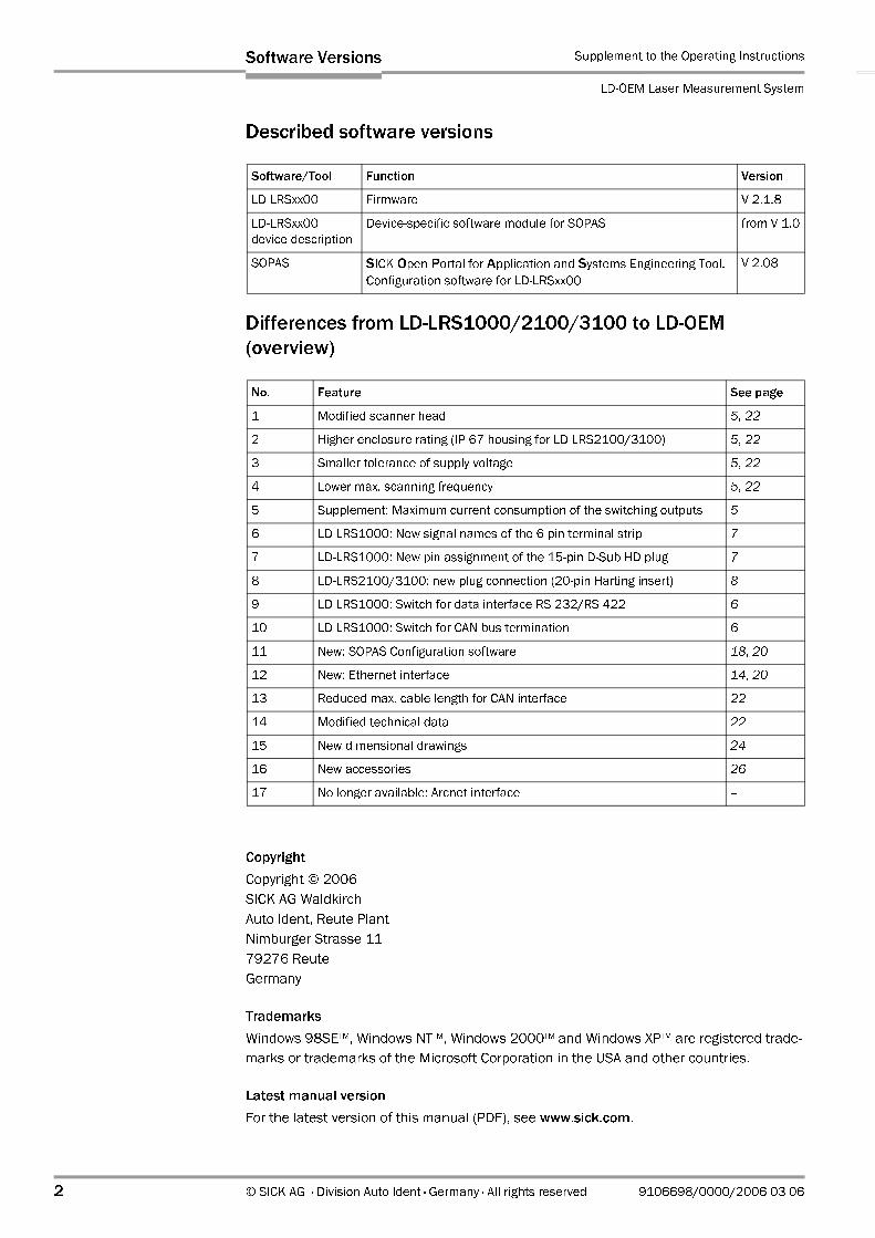
Reference: Signal notation of the terminal strip LD-LRS1000/LD-OEM
15-pin D Sub HD plug
Notation for LD-LRS1000 Notation for LD-OEM (old)
V-EXT +24 V
GND-EXT GND
OUT 1 Alarm 1
OUT 2 Alarm 2
OUT 3 Safe 1
OUT 4 Safe 2
Table 1-5: Comparison: Signal notation of the 6-pin terminal strip LD-LRS1000/LD-OEM
5 6
11
10
15
1 Pin Signal Interface Function
1 24 V DC Power supply
2 CAN L CAN bus (IN/OUT) CAN bus Low
3 CAN H CAN bus (IN/OUT) CAN bus High
4 GND_Data Data interface ground
5 GND Power supply ground
6 RD+ RS 422 Receiver+
7 RD–/RxD RS 422/RS 232 Receiver–
8 TD+ RS 422 Transmitter+
9 TD–/TxD RS 422/RS 232 Transmitter–
10 OUT 1 Switching output 1, function depends on application
11 TPIP Ethernet IN Receiver+
12 TPIN Ethernet IN Receiver–
13 TPOP Ethernet OUT Transmitter+
14 TPON Ethernet OUT Transmitter–
15 OUT 2 Switching output 2, function depends on application
Housing – – Shield
Table 1-6: LD-LRS1000 interface adapter: Pin assignment of 15-pin D Sub HD plug
Chapter 1 Supplement to the Operating Instructions
LD-OEM Laser Measurement System
8 © SICK AG · Division Auto Ident · Germany · All rights reserved 9106698/0000/2006-03-06
Differences from LD-LRSxx00 to LD-OEM
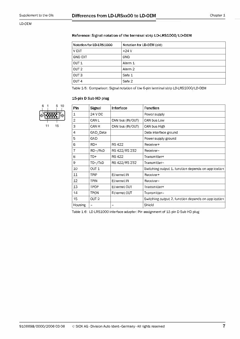
1.3.2 Pin assignment LD-LRS2100/3100
LD-LRS2100: 20-pin Harting socket
Fig. 1-3: LD-LRS2100/3100: Housing of th 20-pin plug connection with Harting insert (socket)
3 x PG 11 (metal) for cable cross diameter
5 to 12 mm (0.2 to 0.47 in)
Cover with 20-pin insert (socket)
(inside view)
11
20
1
10
10
9
8
7
6
5
4
3
2
1
20
19
18
17
16
15
14
13
12
11Pin Signal Interface Function
1 DC 24 V_HZG Heater power supply
2 DC 24 V Electronics power supply
3 OUT 1 Switching output 1 Function depends on application
4 OUT 3 Switching output 3 Function depends on application
5 – n. c. –
6 TxD RS 232 Transmitter–
7 – Reserved
8 CAN H CAN bus (IN/OUT) CAN bus High
9 TPOP Ethernet OUT Transmitter+
10 TPON Ethernet OUT Transmitter–
11 GND_HZG Heater ground
12 GND Electronics ground
13 OUT 2 Switching output 2 Function depends on application
14 OUT 4 Switching output 4 Function depends on application
15 GND_Data Data interfaces ground
16 RxD RS 232 Receiver–
17 – Reserved
18 CAN L CAN bus (IN/OUT) CAN bus Low
19 TPIP Ethernet IN Receiver+
20 TPIN Ethernet IN Receiver–
Housing – – Shield
Table 1-7: LD-LRS2100: Pin assignment ot the 20-pin Harting socket

Supplement to the OIs Chapter 1
LD-OEM
Differences from LD-LRSxx00 to LD-OEM
9106698/0000/2006-03-06 © SICK AG · Division Auto Ident · Germany · All rights reserved 9
LD-LRS3100: 20-pin Harting socket
The cables are routed into the housing via PG cable glands. For connecting the wires, the
20-pin insert (socket) provides screw terminals on its backside.
10
9
8
7
6
5
4
3
2
1
20
19
18
17
16
15
14
13
12
11Pin Signal Interface Function
1 DC 24 V_HZG Heater power supply
2 DC 24 V Electronics power supply
3 OUT 1 Switching output 1 Function depends on application
4 OUT 3 Switching output 3 Function depends on application
5 – n. c. –
6 TD– RS 422 Transmitter–
7 TD+ RS 422 Transmitter+
8 CAN H CAN bus (IN/OUT) CAN bus High
9 TPOP Ethernet OUT Transmitter+
10 TPON Ethernet OUT Transmitter–
11 GND_HZG Heater ground
12 GND Electronics ground
13 OUT 2 Switching output 2 Function depends on application
14 OUT 4 Switching output 4 Function depends on application
15 GND_Data Data interfaces ground
16 RD– RS 422 Receiver–
17 RD+ RS 422 Receiver+
18 CAN L CAN bus (IN/OUT) CAN bus Low
19 TPIP Ethernet IN Receiver+
20 TPIN Ethernet IN Receiver–
Housing – – Shield
Table 1-8: LD-LRS3100: Pin assignment ot the 20-pin Harting socket
Chapter 1 Supplement to the Operating Instructions
LD-OEM Laser Measurement System
10 © SICK AG · Division Auto Ident · Germany · All rights reserved 9106698/0000/2006-03-06
Differences from LD-LRSxx00 to LD-OEM
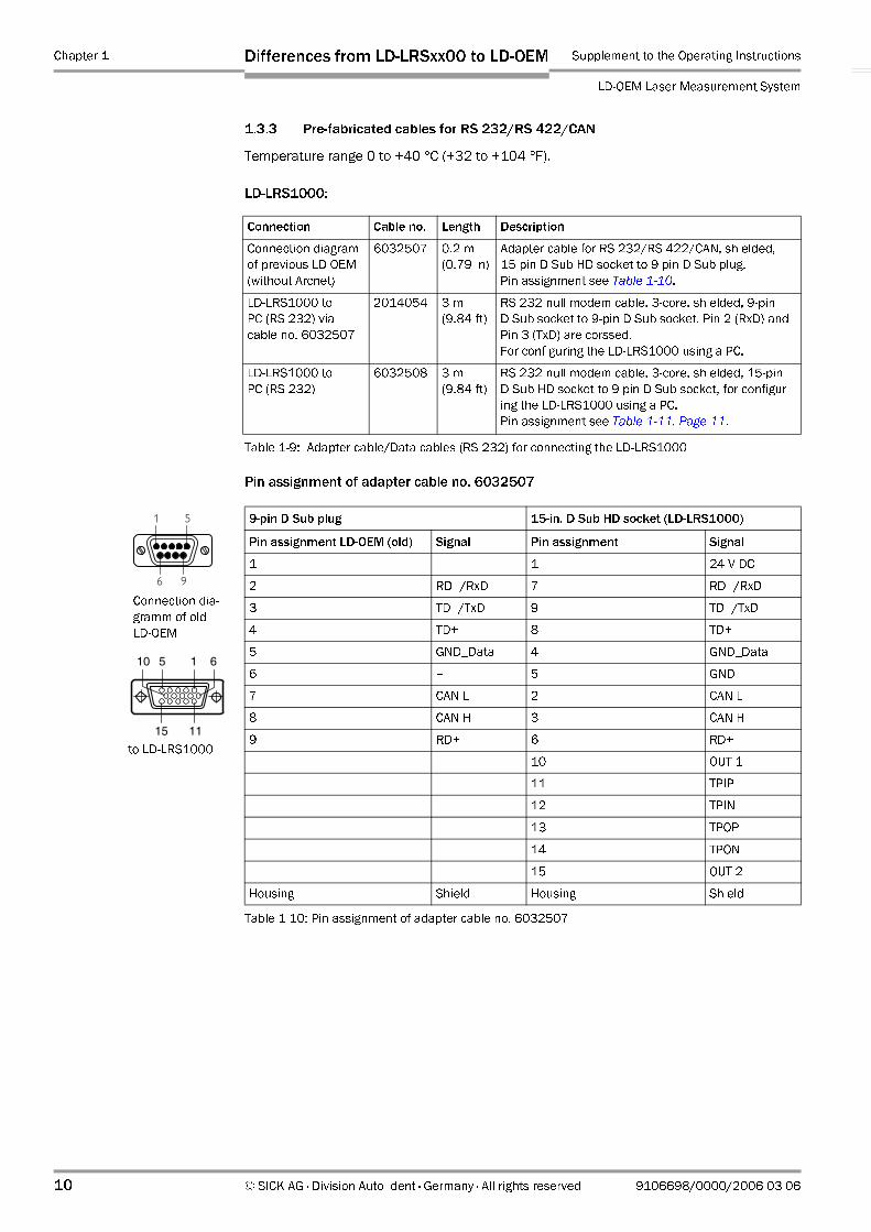
1.3.3 Pre-fabricated cables for RS 232/RS 422/CAN
Temperature range 0 to +40 °C (+32 to +104 °F).
LD-LRS1000:
Pin assignment of adapter cable no. 6032507
Connection Cable no. Length Description
Connection diagram
of previous LD-OEM
(without Arcnet)
6032507 0.2 m
(0.79 in)
Adapter cable for RS 232/RS 422/CAN, shielded,
15-pin D-Sub HD socket to 9-pin D Sub plug.
Pin assignment see Table 1-10.
LD-LRS1000 to
PC (RS 232) via
cable no. 6032507
2014054 3 m
(9.84 ft)
RS 232 null modem cable, 3-core, shielded, 9-pin
D Sub socket to 9-pin D Sub socket. Pin 2 (RxD) and
Pin 3 (TxD) are corssed.
For configuring the LD-LRS1000 using a PC.
LD-LRS1000 to
PC (RS 232)
6032508 3 m
(9.84 ft)
RS 232 null modem cable, 3-core, shielded, 15-pin
D Sub HD socket to 9-pin D Sub socket, for configur-
ing the LD-LRS1000 using a PC.
Pin assignment see Table 1-11, Page 11.
Table 1-9: Adapter cable/Data cables (RS 232) for connecting the LD-LRS1000
9-pin D Sub plug 15-in. D Sub HD socket (LD-LRS1000)
Pin assignment LD-OEM (old) Signal Pin assignment Signal
1 – 1 24 V DC
2 RD–/RxD 7 RD–/RxD
3 TD–/TxD 9 TD–/TxD
4 TD+ 8 TD+
5 GND_Data 4 GND_Data
6 – 5 GND
7 CAN L 2 CAN L
8 CAN H 3 CAN H
9 RD+ 6 RD+
10 OUT 1
11 TPIP
12 TPIN
13 TPOP
14 TPON
15 OUT 2
Housing Shield Housing Shield
Table 1-10: Pin assignment of adapter cable no. 6032507
51
96
1 10
15
6
11
5
Connection dia-
gramm of old
LD-OEM
to LD-LRS1000
Supplement to the OIs Chapter 1
LD-OEM
Differences from LD-LRSxx00 to LD-OEM
9106698/0000/2006-03-06 © SICK AG · Division Auto Ident · Germany · All rights reserved 11
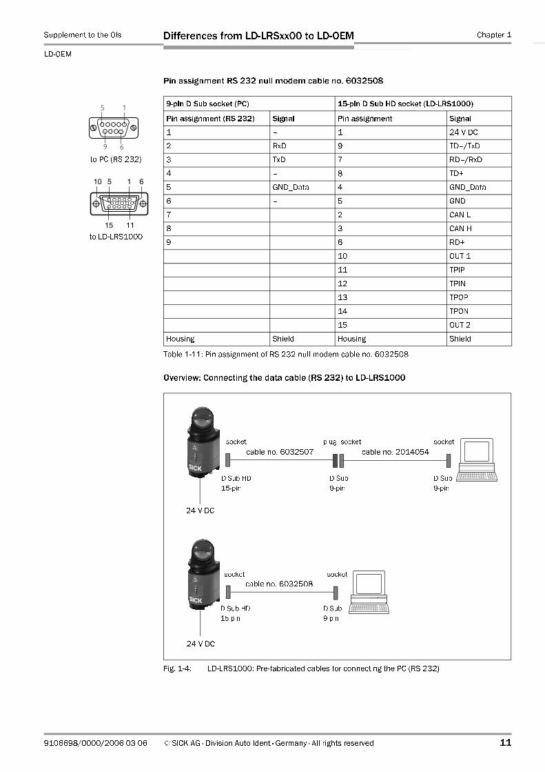
Pin assignment RS 232 null modem cable no. 6032508
Overview: Connecting the data cable (RS 232) to LD-LRS1000
9-pin D Sub socket (PC) 15-pin D Sub HD socket (LD-LRS1000)
Pin assignment (RS 232) Signal Pin assignment Signal
1 – 1 24 V DC
2 RxD 9 TD–/TxD
3 TxD 7 RD–/RxD
4 – 8 TD+
5 GND_Data 4 GND_Data
6 – 5 GND
7 – 2 CAN L
8 – 3 CAN H
9 – 6 RD+
10 OUT 1
11 TPIP
12 TPIN
13 TPOP
14 TPON
15 OUT 2
Housing Shield Housing Shield
Table 1-11: Pin assignment of RS 232 null modem cable no. 6032508
Fig. 1-4: LD-LRS1000: Pre-fabricated cables for connecting the PC (RS 232)
5 1
9 6
1 10
15
6
11
5
to LD-LRS1000
to PC (RS 232)
24 V DC
plugsocket socket socket
cable no. 6032507 cable no. 2014054
24 V DC
socket socket
cable no. 6032508
D Sub
9-pin
D Sub HD
15-pin
D Sub
9-pin
D Sub HD
15-pin
D Sub
9-pin
Chapter 1 Supplement to the Operating Instructions
LD-OEM Laser Measurement System
12 © SICK AG · Division Auto Ident · Germany · All rights reserved 9106698/0000/2006-03-06
Differences from LD-LRSxx00 to LD-OEM
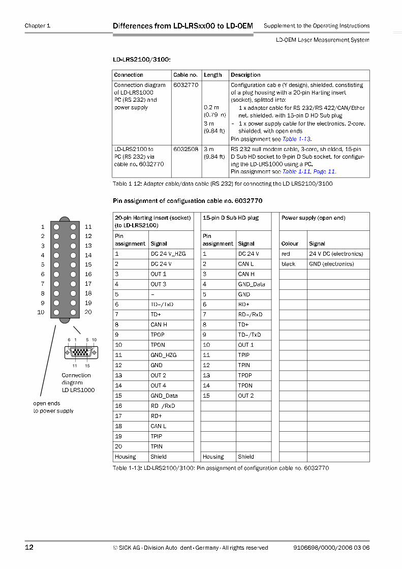
LD-LRS2100/3100:
Pin assignment of configuration cable no. 6032770
Connection Cable no. Length Description
Connection diagram
of LD-LRS1000
PC (RS 232) and
power supply
6032770
0.2 m
(0.79 in)
3 m
(9.84 ft)
Configuration cable (Y design), shielded, constisting
of a plug housing with a 20-pin Harting insert
(socket), splitted into:
– 1 x adapter cable for RS 232/RS 422/CAN/Ether-
net, shielded, with 15-pin D HD Sub plug
– 1 x power supply cable for the electronics, 2-core,
shielded, with open ends
Pin assignment see Table 1-13.
LD-LRS2100 to
PC (RS 232) via
cable no. 6032770
6032508 3 m
(9.84 ft)
RS 232 null modem cable, 3-core, shielded, 15-pin
D Sub HD socket to 9-pin D Sub socket, for configur-
ing the LD-LRS1000 using a PC.
Pin assignment see Table 1-11, Page 11.
Table 1-12: Adapter cable/data cable (RS 232) for connecting the LD-LRS2100/3100
20-pin Harting insert (socket)
(to LD-LRS2100)
15-pin D Sub HD plug Power supply (open end)
Pin
assignment Signal
Pin
assignment Signal Colour Signal
1 DC 24 V_HZG 1 DC 24 V red 24 V DC (electronics)
2 DC 24 V 2 CAN L black GND (electronics)
3 OUT 1 3 CAN H
4 OUT 3 4 GND_Data
5 – 5 GND
6 TD–/TxD 6 RD+
7 TD+ 7 RD–/RxD
8 CAN H 8 TD+
9 TPOP 9 TD–/TxD
10 TPON 10 OUT 1
11 GND_HZG 11 TPIP
12 GND 12 TPIN
13 OUT 2 13 TPOP
14 OUT 4 14 TPON
15 GND_Data 15 OUT 2
16 RD–/RxD
17 RD+
18 CAN L
19 TPIP
20 TPIN
Housing Shield Housing Shield
Table 1-13: LD-LRS2100/3100: Pin assignment of configuration cable no. 6032770
10
9
8
7
6
5
4
3
2
1
20
19
18
17
16
15
14
13
12
11
open ends
to power supply
5 6
11
10
15
1
Connection
diagram
LD-LRS1000
Supplement to the OIs Chapter 1
LD-OEM
Differences from LD-LRSxx00 to LD-OEM
9106698/0000/2006-03-06 © SICK AG · Division Auto Ident · Germany · All rights reserved 13
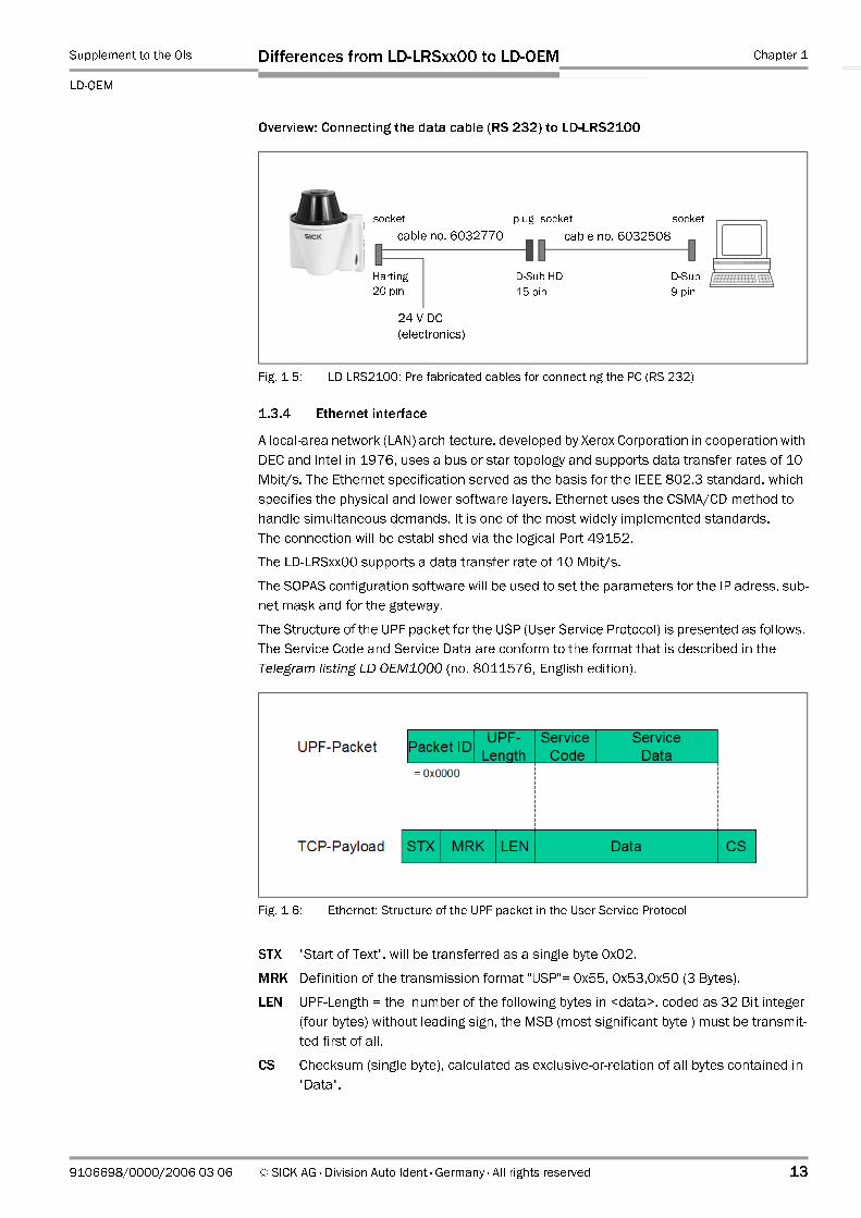
Overview: Connecting the data cable (RS 232) to LD-LRS2100
1.3.4 Ethernet interface
A local-area network (LAN) architecture, developed by Xerox Corporation in cooperation with
DEC and Intel in 1976, uses a bus or star topology and supports data transfer rates of 10
Mbit/s. The Ethernet specification served as the basis for the IEEE 802.3 standard, which
specifies the physical and lower software layers. Ethernet uses the CSMA/CD method to
handle simultaneous demands. It is one of the most widely implemented standards.
The connection will be established via the logical Port 49152.
The LD-LRSxx00 supports a data transfer rate of 10 Mbit/s.
The SOPAS configuration software will be used to set the parameters for the IP adress, sub-
net mask and for the gateway.
The Structure of the UPF packet for the USP (User Service Protocol) is presented as follows.
The Service Code and Service Data are conform to the format that is described in the
Telegram listing LD-OEM1000 (no. 8011576, English edition).
STX "Start of Text", will be transferred as a single byte 0x02.
MRK Definition of the transmission format "USP"= 0x55, 0x53,0x50 (3 Bytes).
LEN UPF-Length = the number of the following bytes in <data>, coded as 32 Bit integer
(four bytes) without leading sign, the MSB (most significant byte ) must be transmit-
ted first of all.
CS Checksum (single byte), calculated as exclusive-or-relation of all bytes contained in
"Data".
Fig. 1-5: LD-LRS2100: Pre-fabricated cables for connecting the PC (RS 232)
Fig. 1-6: Ethernet: Structure of the UPF packet in the User Service Protocol
24 V DC
(electronics)
Harting
20-pin
plug
cable no. 6032770
socket socket
D-Sub
9-pin
cable no. 6032508
D-Sub HD
15-pin
socket

Chapter 1 Supplement to the Operating Instructions
LD-OEM Laser Measurement System
14 © SICK AG · Division Auto Ident · Germany · All rights reserved 9106698/0000/2006-03-06
Differences from LD-LRSxx00 to LD-OEM
Connecting the LD-LRSxx00 to Ethernet
According to Table 1-14 for LD-LRS1000 and Table 1-15 for LRS2100/3100, you can make
an IEEE 802.3-compatible network interface using a shielded RJ45 connection.
The pin assignments correspond to an MDI port, so that the connection to the hub or switch
is accomplished using 1:1 shielded patch cable.
LD-LRS1000:
LD-LRS2100/3100:
Signal LD-LRS1000 Pin (15-pin D Sub HD plug) Pin (8-pin RJ-45 socket)
TPIP 11 3
TPIN 12 6
TPOP 13 1
TPON 14 2
Table 1-14: LD-LRS1000 pin assignment of the 15-pin D Sub HD plug for Ethernet connection (MDI
interface)
Signal LD-LRS2100/3100 Pin (20-pin Harting socket) Pin (8-pin RJ-45 socket)
TPIP 19 3
TPIN 20 6
TPOP 9 1
TPON 10 2
Table 1-15: LD-LRS2100/3100 pin assignment of the 20-pin Harting socket for Ethernet connection
(MDI interface)

Supplement to the OIs Chapter 1
LD-OEM
Differences from LD-LRSxx00 to LD-OEM
9106698/0000/2006-03-06 © SICK AG · Division Auto Ident · Germany · All rights reserved 15
Pre-fabricated cables for connecting the PC directly (peer-to-peer)
Temperature range 0 to +40 °C (+32 to +104 °F).
LD-LRS1000:
Pin assignment of Ethernet cross-over cable Nr. 6032509
LD-LRS2100/3100:
Connection Cable no. Length Description
LD-LRS1000 to
PC (Ethernet)
6032509 3 m
(9.84 ft)
Ethernet cross-over cable, shielded, 15-pin D Sub HD
socket to 8-pin RJ-45 plug, for configuring the LD-
LRS1000 using a PC. Pin assignment see Table 1-17
Table 1-16: Data cables (Ethernet) for connecting the LD-LRS1000
RJ-45 plug (PC) 15-pin D Sub HD socket (LD-LRS1000)
Pin assignment (Ethernet) Signal Pin assignment Signal
1 24 V DC
9 TD–/TxD
7 RD–/RxD
8 TD+
4 GND_Data
5 GND
2 CAN L
3 CAN H
6 RD+
10 OUT 1
1 TPOP 11 TPIP
2 TPON 12 TPIN
3 TPIP 13 TPOP
6 TPIN 14 TPON
15 OUT 2
Housing Shield Housing Shield
Table 1-17: Pin assignment of Ethernet cross-over cable Nr. 6032509
Connection Cable no. Length Description
Connection diagram
of LD-LRS1000
PC (RS 232) and
power supply
6032770
0.2 m
(0.79 in)
3 m
(9.84 ft)
Configuration cable (Y design), shielded, constisting
of a plug housing with a 20-pin Harting insert
(socket), splitted into:
– 1 x adapter cable for RS 232/RS 422/CAN/Ether-
net, shielded, with 15-pin D HD Sub plug
– 1 x power supply cable for the electronics, 2-core,
shielded, with open ends
Pin assignment see Table 1-13, Page 12.
LD-LRS1000 to
PC (Ethernet) via
cable no. 6032770
6032509 3 m
(9.84 ft)
Ethernet cross-over cable, shielded, 15-pin D Sub HD
socket to 8-pin RJ-45 plug, for configuring the LD-
LRS1000 using a PC. Pin assignment see Table 1-17
Table 1-18: Adapter cable/data cable (Ethernet) for connecting the LD-LRS2100/3100
1 10
15
6
11
5
to LD-LRS1000
RJ-45

Chapter 1 Supplement to the Operating Instructions
LD-OEM Laser Measurement System
16 © SICK AG · Division Auto Ident · Germany · All rights reserved 9106698/0000/2006-03-06
Differences from LD-LRSxx00 to LD-OEM
Overview: Connecting the data cable (Ethernet) to LD-LRS1000/2100/3100
Note For connecting the LD-LRSxx00 to a hub/switch additionally an RJ-45 coupler (2 x socket)
and a standard cross-over cable are required.
Fig. 1-7: Pre-fabricated cables for connecting the PC (Ethernet)
LD-LRS1000
LD-LRS2100/3100
24 V DC
D Sub HD
15-pin
socket
RJ-45
8-pin
plug
cable no. 6032509
(cross-over)
24 V DC
(electronics)
Harting
20-pin
plug
cable no. 6032770
socket plug
cable no. 6032509
(cross-over)
RJ-45
8-pin
D Sub HD
15-pin
socket
Fig. 1-8: Ethernet: RJ-45 coupler (2 x socket)

Supplement to the OIs Chapter 1
LD-OEM
Differences from LD-LRSxx00 to LD-OEM
9106698/0000/2006-03-06 © SICK AG · Division Auto Ident · Germany · All rights reserved 17
1.4 Mounting
Note Do not open the device. The producer warranty will be forfeited if the device is opened.
1.4.1 Selecting the installation location
Mount the LD-LRS2100/3100 in such a way that it is protected from direct sunlight (if re-
quired use a suitable cover). This reduces the risk of an unpermissible rise of temperature
inside of the system housing.
1.4.2 Mounting the LD-LRS2100/3100
Mount the LD-LRS2100/3100 in such a way that the black scanning window is positioned
downwards. Thus ensuring that any condensation on the scanning window will run off and
additionally reduces the risk of dust collection on the window.
Note Prerequisites for the enclosure rating IP 67
To maintain the enclosure rating IP 67 do not remove the scanning window (refer to the pro-
ducer warranty conditions above). The connector on the back plane must be tightened. The
not used cable glands of the connector must be covered.
Fig. 1-9: LD-LRS2100/3100: Preferred mounting position
Scanning window

Chapter 1 Supplement to the Operating Instructions
LD-OEM Laser Measurement System
18 © SICK AG · Division Auto Ident · Germany · All rights reserved 9106698/0000/2006-03-06
Differences from LD-LRSxx00 to LD-OEM
1.5 Quick start with default settings by factory
1.5.1 Quick start using the RS 232/RS 422 data interface
LD-LRS1000:
1. Unscrew the interface adapter (at bottom of the device).
2. Select the data interface (RS 232 or RS 422) using the DIP switch 1 inside of the inter-
face adapter.
3. Connect the 24 DC V power supply cable to the 6-pin terminal strip via the cable gland
of the interface adapter. Use a wire cross-section of at least 1 mm2 (18 AWG) at a max-
imum of 20 m (65.6 ft) cable lenght.
4. Tighten the interface adapter.
5. Connect the 15-pin D Sub HD plug of the interface adapter to the RS 232 or RS 422
interface of the PC using an appropriate interface cable (depends on the selected inter-
face type). An RS 232/RS 422 converter may be required.
For RS 232 the 3-core null modem cable no. 6032508 (15-pin D-Sub HD socket to 9-
pin D-Sub socket) is available. See also Table 1-9, Page 10 and Fig. 1-4, Page 11.
LD-LRS2100/3100:
1. Connect the 24 DC V power supply for the electronics to the 20-pin socket of the Harting
plug connection.
2. If the LD-LRS2100/3100 is used in the outdoor, connect the heater. To do so, use a
seperate 24 V DC power supply unit.
3. Connect the RS 232 data interface (LD-LRS2100) or the RS 422 data interface (LD-
LRS3100) of the 20-pin socket to the PC (cross the wires for transmitter and receiver).
An RS 232/RS 422 converter may be required.
For RS 232 the configuration cable no. 6032770 (20-pin Harting socket to 15pin D Sub
HD plug as well as to open ends for power supply of the electronics) in combination with
the cable no. 6032508 is available. See also Table 1-12, Page 12 and Fig. 1-5,
Page 13.
All LD-LRSxx00:
1. Switch on the power supply for the LD-LRSxx00.
The LD-LRSxx00 iniates a self-test. After the initialisation the green LED begins to flash.
The scanning head does not yet rotate.
2. Switch on your PC and start WindowsTM (at least W98SETM).
3. Install the “SOPAS Engineering Tool“ configuration software on the PC and start the
program.
4. In the dialog box select the NEW PROJECT option.
5. Under SCAN ASSISTANT, CONFIGURATION, SERIAL PORT/STANDARD PROTOCOL click the ENABLE
SERIAL COMMUNICATION option.
6. Click the ADVANCED... button.
7. For CoLa dialect, select the BINARY option.
Disable all preselected baud rates and enable the “115 kBd“ option.
Port settings: 8 data bits, 1 stop bit, no parity.
Confirm with OK.
8. Click the SCAN button.
9. Select the listed sensor (LD-LRSxx00). Confirm with ADD DEVICE.
Supplement to the OIs Chapter 1
LD-OEM
Differences from LD-LRSxx00 to LD-OEM
9106698/0000/2006-03-06 © SICK AG · Division Auto Ident · Germany · All rights reserved 19
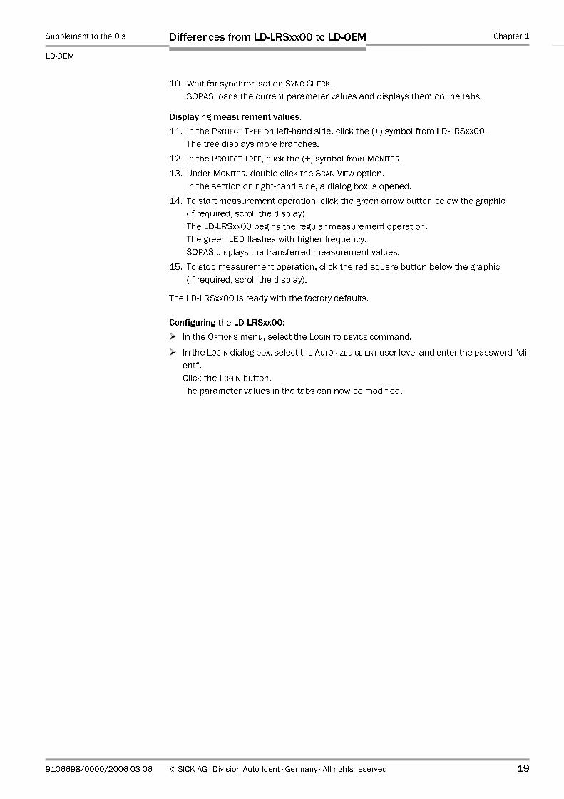
10. Wait for synchronisation SYNC CHECK.
SOPAS loads the current parameter values and displays them on the tabs.
Displaying measurement values:
11. In the PROJECT TREE on left-hand side, click the (+) symbol from LD-LRSxx00.
The tree displays more branches.
12. In the PROJECT TREE, click the (+) symbol from MONITOR.
13. Under MONITOR, double-click the SCAN VIEW option.
In the section on right-hand side, a dialog box is opened.
14. To start measurement operation, click the green arrow button below the graphic
(if required, scroll the display).
The LD-LRSxx00 begins the regular measurement operation.
The green LED flashes with higher frequency.
SOPAS displays the transferred measurement values.
15. To stop measurement operation, click the red square button below the graphic
(if required, scroll the display).
The LD-LRSxx00 is ready with the factory defaults.
Configuring the LD-LRSxx00:
In the OPTIONS menu, select the LOGIN TO DEVICE command.
In the LOGIN dialog box, select the AUTORIZED CLIENT user level and enter the password “cli-
ent“.
Click the LOGIN button.
The parameter values in the tabs can now be modified.

Chapter 1 Supplement to the Operating Instructions
LD-OEM Laser Measurement System
20 © SICK AG · Division Auto Ident · Germany · All rights reserved 9106698/0000/2006-03-06
Differences from LD-LRSxx00 to LD-OEM
1.5.2 Quick start using the Ethernet interface (10 Mbit/s)
Note See also Chapter 1.3.4 Ethernet interface, Page 13.
LD-LRS1000:
1. Unscrew the interface adapter (at bottom of the device).
2. Connect the 24 DC V power supply cable to the 6-pin terminal strip via the cable gland
of the interface adapter. Use a wire cross-section of at least 1 mm2 (18 AWG) at a max-
imum of 20 m (65.6 ft) cable lenght.
3. Tighten the interface adapter.
4. Connect the Ethernet cross-over cable no. 6032509 with the 15-pin D Sub HD socket
to the interface adapter and with the 8-pin RJ-45 plug to the PC. See also Table 1-16,
Page 15 and Fig. 1-7, Page 16.
For connecting the LD-LRS1000 to a hub/switch additionally an RJ-45 coupler (2 x
socket) and a standard cross-over cable is required.
LD-LRS2100/3100:
1. Connect the 24 DC V power supply for the electronics to the 20-pin socket of the Harting
plug connection.
2. If the LD-LRS2100/3100 is used in the outdoor, connect the heater. To do so, use a
seperate 24 V DC power supply unit.
3. Connect the Ethernet interface of the 20-pin socket to the PC (cross the wires for trans-
mitter and receiver).
To do so, use the configuration cable no. 6032770 (20-pin Harting socket to 15pin D
Sub HD plug as well as to open ends for power supply of the electronics) in combination
with the cable no. 6032509. See also Table 1-18, Page 15 and Fig. 1-7, Page 16.
For connecting the LD-LRS2100/3100 to a hub/switch additionally an RJ-45 coupler
(2 x sokket) and a standard cross-over cable are required.
All LD-LRSxx00:
1. Switch on the power supply for the LD-LRSxx00.
The LD-LRSxx00 iniates a self-test. After the initialisation the green LED begins to flash.
The scanning head does not yet rotate.
2. Switch on your PC and start WindowsTM (at least W98SETM).
3. Check whether the TCP/IP protocol is enabled under Windows.
(Windows XP: Start > Settings > Control Panel > Network Connections > LAN Connenc-
tion > Properties > Internet Protocol (TCP/IP)).
4. If not, start now the Internet protocol (TCP/IP).
5. Set the link speed of the network card to “Auto detect“ or “10 Mbps/Full duplex“.
6. Under Start > Settings > Control Panel > Network Connections, select the LAN connec-
tion to which the LD-LRSxx00 is connected.
7. Under “Properties“ activate the Internet protocol (TCP/IP).
8. Click the “Properties“ button and enter the PC address “192.168.1.1“ and the sub-net
mask “255.255.255.0“ under “IP address“.
9. Install the “SOPAS Engineering Tool“ configuration software on the PC and start the
program.
10. In the dialog box select the NEW PROJECT option.
11. Under SCAN ASSISTANT, CONFIGURATION, INTERNET PROTOCOL/IP COMMUNICATION click the
ENABLE IP COMMUNICATION option.

Supplement to the OIs Chapter 1
LD-OEM
Differences from LD-LRSxx00 to LD-OEM
9106698/0000/2006-03-06 © SICK AG · Division Auto Ident · Germany · All rights reserved 21
12. Click the ADD button.
In the dialog box enter the address “192.168.1.10“ and confirm with OK.
13. Click the ADVANCED... button.
For CoLa dialect, select the BINARY option and confirm with OK.
14. Click the SCAN button.
15. Select the listed sensor (LD-LRSxx00). Confirm with ADD DEVICE.
16. Wait for synchronisation SYNC CHECK.
SOPAS loads the current parameter values and displays them on the tabs.
Displaying measurement values:
17. In the PROJECT TREE on left-hand side, click the (+) symbol from LD-LRSxx00.
The tree displays more branches.
18. In the PROJECT TREE, click the (+) symbol from MONITOR.
19. Under MONITOR, double-click the SCAN VIEW option.
In the section on right-hand side, a dialog box is opened.
20. To start measurement operation, click the green arrow button below the graphic
(if required, scroll the display).
The LD-LRSxx00 begins the regular measurement operation. The green LED flashes
with higher frequency.
SOPAS displays the transferred measurement values.
21. To stop measurement operation, click the red square button below the graphic
(if required, scroll the display).
The LD-LRSxx00 is ready with the factory defaults.
Configuring the LD-LRSxx00:
In the OPTIONS menu, select the LOGIN TO DEVICE command.
In the LOGIN dialog box, select the AUTORIZED CLIENT user level and enter the password “cli-
ent“.
Click the LOGIN button.
The parameter values in the tabs can now be modified.
Chapter 1 Supplement to the Operating Instructions
LD-OEM Laser Measurement System
22 © SICK AG · Division Auto Ident · Germany · All rights reserved 9106698/0000/2006-03-06
Differences from LD-LRSxx00 to LD-OEM
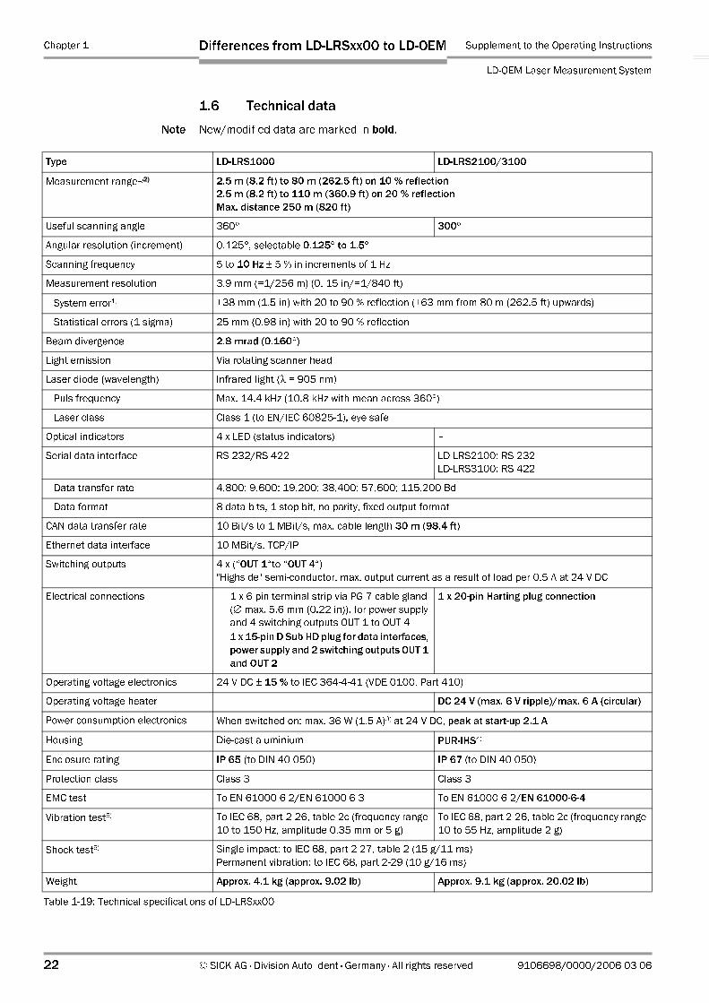
1.6 Technical data
Note New/modified data are marked in bold.
Type LD-LRS1000 LD-LRS2100/3100
Measurement range1)2) 2.5 m (8.2 ft) to 80 m (262.5 ft) on 10 % reflection
2.5 m (8.2 ft) to 110 m (360.9 ft) on 20 % reflection
Max. distance 250 m (820 ft)
Useful scanning angle 360° 300°
Angular resolution (increment) 0.125°, selectable 0.125° to 1.5°
Scanning frequency 5 to 10 Hz ± 5 % in increments of 1 Hz
Measurement resolution 3.9 mm (=1/256 m) (0. 15 in/=1/840 ft)
System error1) ±38 mm (1.5 in) with 20 to 90 % reflection (±63 mm from 80 m (262.5 ft) upwards)
Statistical errors (1 sigma) 25 mm (0.98 in) with 20 to 90 % reflection
Beam divergence 2.8 mrad (0.160°)
Light emission Via rotating scanner head
Laser diode (wavelength) Infrared light (λ = 905 nm)
Puls frequency Max. 14.4 kHz (10.8 kHz with mean across 360°)
Laser class Class 1 (to EN/IEC 60825-1), eye safe
Optical indicators 4 x LED (status indicators) –
Serial data interface RS 232/RS 422 LD-LRS2100: RS 232
LD-LRS3100: RS 422
Data transfer rate 4,800; 9,600; 19,200; 38,400; 57,600; 115,200 Bd
Data format 8 data bits, 1 stop bit, no parity, fixed output format
CAN data transfer rate 10 Bit/s to 1 MBit/s, max. cable length 30 m (98.4 ft)
Ethernet data interface 10 MBit/s, TCP/IP
Switching outputs 4 x (“OUT 1“to “OUT 4“)
"Highside" semi-conductor, max. output current as a result of load per 0.5 A at 24 V DC
Electrical connections – 1 x 6-pin terminal strip via PG 7 cable gland
(∅ max. 5.6 mm (0.22 in)), for power supply
and 4 switching outputs OUT 1 to OUT 4
– 1 x 15-pin D Sub HD plug for data interfaces,
power supply and 2 switching outputs OUT 1
and OUT 2
1 x 20-pin Harting plug connection
Operating voltage electronics 24 V DC ± 15 % to IEC 364-4-41 (VDE 0100, Part 410)
Operating voltage heater – DC 24 V (max. 6 V ripple)/max. 6 A (circular)
Power consumption electronics When switched on: max. 36 W (1.5 A)3) at 24 V DC, peak at start-up 2.1 A
Housing Die-cast aluminium PUR-IHS4)
Enclosure rating IP 65 (to DIN 40 050) IP 67 (to DIN 40 050)
Protection class Class 3 Class 3
EMC test To EN 61000-6-2/EN 61000-6-3 To EN 61000-6-2/EN 61000-6-4
Vibration test5) To IEC 68, part 2-26, table 2c (frequency range
10 to 150 Hz, amplitude 0.35 mm or 5 g)
To IEC 68, part 2-26, table 2c (frequency range
10 to 55 Hz, amplitude 2 g)
Shock test5) Single impact: to IEC 68, part 2-27, table 2 (15 g/11 ms)
Permanent vibration: to IEC 68, part 2-29 (10 g/16 ms)
Weight Approx. 4.1 kg (approx. 9.02 lb) Approx. 9.1 kg (approx. 20.02 lb)
Table 1-19: Technical specifications of LD-LRSxx00
Supplement to the OIs Chapter 1
LD-OEM
Differences from LD-LRSxx00 to LD-OEM
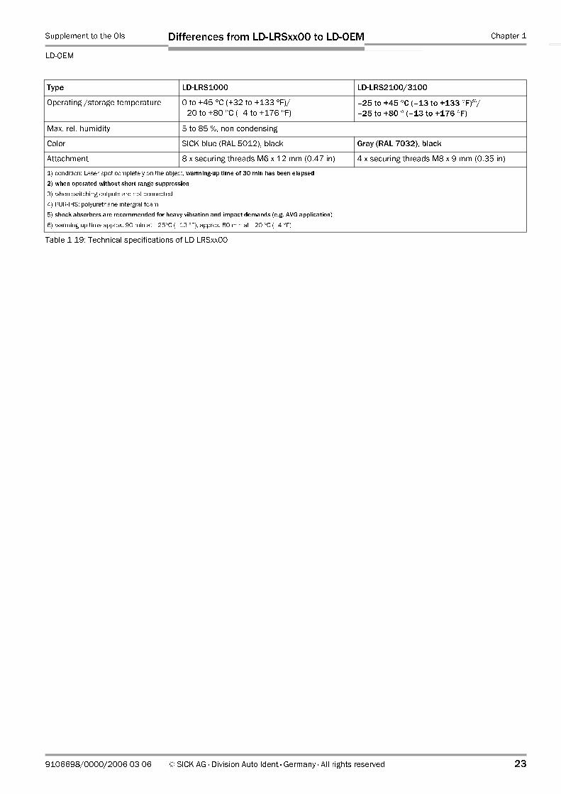
9106698/0000/2006-03-06 © SICK AG · Division Auto Ident · Germany · All rights reserved 23
Operating /storage temperature 0 to +45 °C (+32 to +133 °F)/
–20 to +80 °C (–4 to +176 °F)
–25 to +45 °C (–13 to +133 °F)6)/
–25 to +80 ° (–13 to +176 °F)
Max. rel. humidity 5 to 85 %, non condensing
Color SICK blue (RAL 5012), black Gray (RAL 7032), black
Attachment 8 x securing threads M6 x 12 mm (0.47 in) 4 x securing threads M8 x 9 mm (0.35 in)
1) condition: Laser spot completely on the object, warming-up time of 30 min has been elapsed
2) when operated without short range suppression
3) when switching outputs are not connected
4) PUR-IHS: polyurethane intergral foam
5) shock absorbers are recommended for heavy vibration and impact demands (e.g. AVG application)
6) warming-up time approx. 90 min at –25°C (–13 °F), approx. 80 min at –20 °C (–4 °F)
Type LD-LRS1000 LD-LRS2100/3100
Table 1-19: Technical specifications of LD-LRSxx00

Chapter 1 Supplement to the Operating Instructions
LD-OEM Laser Measurement System
24 © SICK AG · Division Auto Ident · Germany · All rights reserved 9106698/0000/2006-03-06
Differences from LD-LRSxx00 to LD-OEM
1.7 Dimensional drawings
1.7.1 LD-LRS1000
Fig. 1-10: LD-LRS1000: Dimensions of the IP 65 housing
All dimensions in mm
mm
inch
17
0.55
48
1.9
49
1.93
57.5
2.26
94
3.7
96
3.78
103
4
118.5
4.67
120.5
4.75
135
5.32
164.5
6.48
232
9.14
277
10.9
Cable gland PG 7
Supplement to the OIs Chapter 1
LD-OEM
Differences from LD-LRSxx00 to LD-OEM
9106698/0000/2006-03-06 © SICK AG · Division Auto Ident · Germany · All rights reserved 25
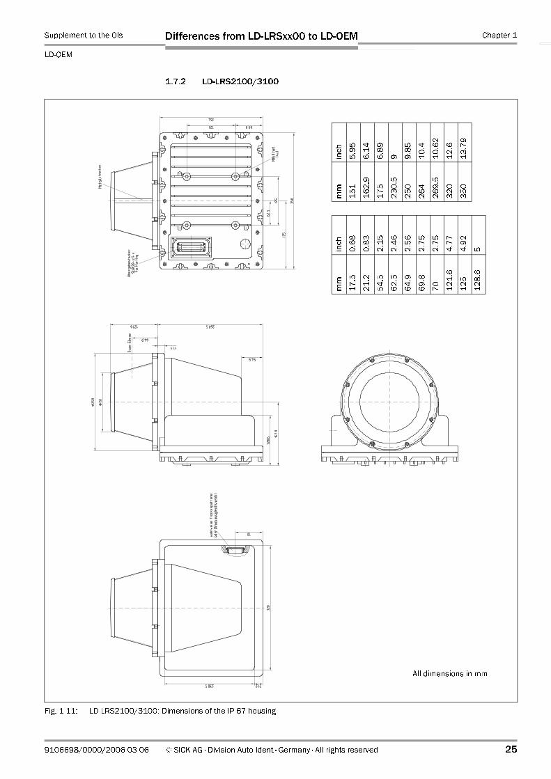
1.7.2 LD-LRS2100/3100
Fig. 1-11: LD-LRS2100/3100: Dimensions of the IP 67 housing
All dimensions in mm
mm
inch
17.5
0.68
21.2
0.83
54.5
2.15
62.5
2.46
64.9
2.56
69.8
2.75
70
2.75
121.6
4.77
125
4.92
128.6
5
mm
inch
151
5.95
162.9
6.14
175
6.89
230.5
9
250
9.85
264
10.4
269.5
10.62
320
12.6
350
13.79
Chapter 1 Supplement to the Operating Instructions
LD-OEM Laser Measurement System
26 © SICK AG · Division Auto Ident · Germany · All rights reserved 9106698/0000/2006-03-06
Differences from LD-LRSxx00 to LD-OEM
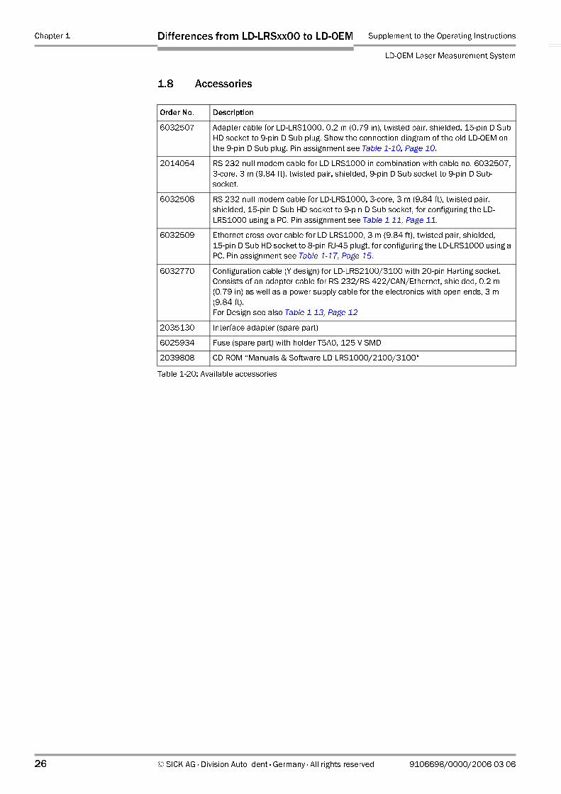
1.8 Accessories
Order No. Description
6032507 Adapter cable for LD-LRS1000, 0.2 m (0.79 in), twisted pair, shielded, 15-pin D Sub
HD socket to 9-pin D Sub plug. Show the connection diagram of the old LD-OEM on
the 9-pin D Sub plug. Pin assignment see Table 1-10, Page 10.
2014054 RS 232 null modem cable for LD-LRS1000 in combination with cable no. 6032507,
3-core, 3 m (9.84 ft), twisted pair, shielded, 9-pin D Sub socket to 9-pin D Sub-
socket.
6032508 RS 232 null modem cable for LD-LRS1000, 3-core, 3 m (9.84 ft), twisted pair,
shielded, 15-pin D Sub HD socket to 9-pin D Sub socket, for configuring the LD-
LRS1000 using a PC. Pin assignment see Table 1-11, Page 11.
6032509 Ethernet cross-over cable for LD-LRS1000, 3 m (9.84 ft), twisted pair, shielded,
15-pin D Sub HD socket to 8-pin RJ-45 plugt, for configuring the LD-LRS1000 using a
PC. Pin assignment see Table 1-17, Page 15.
6032770 Configuration cable (Y design) for LD-LRS2100/3100 with 20-pin Harting socket.
Consists of an adapter cable for RS 232/RS 422/CAN/Ethernet, shielded, 0.2 m
(0.79 in) as well as a power supply cable for the electronics with open ends, 3 m
(9.84 ft).
For Design see also Table 1-13, Page 12
2035130 Interface adapter (spare part)
6025934 Fuse (spare part) with holder T5A0, 125 V SMD
2039808 CD-ROM “Manuals & Software LD-LRS1000/2100/3100“
Table 1-20: Available accessories

Supplement to the OIs Chapter 2
LD-OEM
EC Declaration of Conformity
9106698/0000/2006-03-06 © SICK AG · Division Auto Ident · Germany · All rights reserved 27
2 EC Declaration of Conformity
2.1 Fulfillment of the EU Machine Guidelines
SICK AG confirms that the LD-LRSxx00 conforms to the specifications of the EU machine
guidelines in accordance with EU Machine Guideline 89/392/EEC, Appendix IIC.
2.1.1 EC Declaration of Conformity
Fig. 2-1, Page 28 shows a scaled down copy of the EC Declaration of conformity,
page 1.
Complete copy of the EC Declaration of conformity on request.

Chapter 2 Supplement to the Operating Instructions
LD-OEM Laser Measurement System
28 © SICK AG · Division Auto Ident · Germany · All rights reserved 9106698/0000/2006-03-06
EC Declaration of Conformity
Fig. 2-1: Copy of the EC Declaration of Conformity, page 1 (scaled down)
Supplement to the OIs Chapter 2
LD-OEM
EC Declaration of Conformity
9106698/0000/2006-03-06 © SICK AG · Division Auto Ident · Germany · All rights reserved 29
Notes:
SICK AG | Waldkirch/Reute | Germany | www.sick.com
AustraliaPhone +61 3 9497 4100 1800 33 48 02 – tollfreeE-Mail [email protected]
Belgium/LuxembourgPhone +32 (0)2 466 55 66E-Mail [email protected]
BrasilPhone +55 11 5091-4900E-Mail [email protected]
Ceská RepublikaPhone +420 2 57 91 18 50E-Mail [email protected]
ChinaPhone +852-2763 6966E-Mail [email protected]
DanmarkPhone +45 45 82 64 00E-Mail [email protected]
DeutschlandPhone +49 (0)2 11 53 01-270E-Mail [email protected]
EspañaPhone +34 93 480 31 00E-Mail [email protected]
FrancePhone +33 1 64 62 35 00E-Mail [email protected]
Great BritainPhone +44 (0)1727 831121E-Mail [email protected]
IndiaPhone +91–22–2822 7084E-Mail [email protected]
ItaliaPhone +39 02 27 40 93 19E-Mail [email protected]
JapanPhone +81 (0)3 3358 1341E-Mail [email protected]
NederlandsPhone +31 (0)30 229 25 44E-Mail [email protected]
Norge Phone +47 67 81 50 00E-Mail [email protected]
ÖsterreichPhone +43 (0)22 36 62 28 8-0E-Mail [email protected]
PolskaPhone +48 22 837 40 50E-Mail [email protected]
Republic of KoreaPhone +82-2 786 6321/4E-Mail [email protected]
Republika SlowenijaPhone +386 (0)1-47 69 990E-Mail [email protected]
RussiaPhone +7 95 775 05 30E-Mail [email protected]
SchweizPhone +41 41 619 29 39E-Mail [email protected]
SingaporePhone +65 6744 3732E-Mail [email protected]
SuomiPhone +358-9-25 15 800E-Mail [email protected]
SverigePhone +46 8 680 64 50E-Mail [email protected]
TaiwanPhone +886 2 2365-6292E-Mail [email protected]
TürkiyePhone +90 216 388 95 90 pbxE-Mail [email protected]
USA/Canada/MéxicoPhone +1(952) 941-6780 1 800-325-7425 – tollfreeE-Mail [email protected]
More representatives and agencies in all major industrial nations at www.sick.com
9106
698/
2006
-03-
06 •
5M
/TR
<PM
6.5/
FM7.
0/PD
F>/V
D .
Prin
ted
in G
erm
any
. Su
bjec
t to
chan
ge w
ithou
t not
ice
. Th
e sp
ecifi
ed p
rodu
ct fe
atur
es a
nd te
chni
cal d
ata
do n
ot re
pres
ent a
ny g
uara
ntee
. 0
5 Af
t int
55