lcv 30lb/30xlb/50xlb - cnc services and …csicncservices.com/catalogues/lcv30lb_xlb_50xlb.pdf ·...
TRANSCRIPT

VERTICAL MACHINING CENTER
LCV 30LB/30XLB/50XLB
Ⓒ SMEC 2016.04-NO.1❖ Design and specifications subject to change without notice.
www.esmec.com
SMEC Co., Ltd.157-10, Goldenroot-ro, Juchon-myeon, Gimhae-si, Gyeongsangnam-do, KoreaTel +82 55 340 4800 Fax +82 55 340 4740http://www.esmec.com

Smart One, Global One
SAM
SUN
G M
achi
ning
Too
lsLC
V 3
0LB
/30
XLB
2 3
Item LCV 30LB LCV 30XLB
Table Size 2,200 x 400mm 4,130 x 400mm
Travels (X/Y/Z) 2,000/350/330mm 4,000/350/330mm
Spindle Speed 10,000rpm 10,000rpm
Spindle Motor 3.7/5.5 (5.5/7.5)kW 3.7/5.5 (5.5/7.5)kW
Tool Shank BT30 BT30
Rapid Traverse (X/Y/Z) 30/48/48 m/min 26/48/48 m/min
LCV 30LB/XLB
- Able to handle customer's work size
- Incomparable non-cutting time for large machining center
- Significantly reduced non-cutting time with the ATC attached directly to the column
Offers high productivity and efficiency while meeting the various needs of the production floor with its unique structural design
LCV 30LB/XLB, Designed for Ultra Precision and High Productivity Machining
Z-axis 330mm
X-axis 4,000mm
Y-axis 350mm
•1988 - Started as Samsung Heavy Industries Machine Tools Business
•1989 - Horizontal and vertical machining center technology partnership with OKK Japan
•1991 - Turning center and vertical machining center technology partnership with Mori Seiki
•1996 - 5-sided processing center technology partnership with Toshiba
•1999 - Spun out from Samsung Aerospace Industries and established SMEC Co., Ltd
SMEC Company Engineering Machine Tools Samsung
LCV 30LB/30XLB/50XLBVERTICAL MACHINING CENTER
SAM
SUN
G M
achi
ning
Too
lsLC
V 3
0LB
/30
XLB
4 5
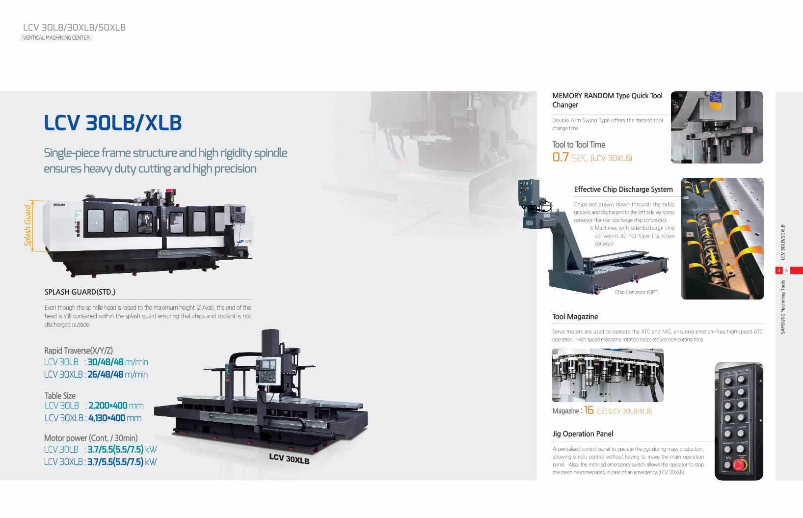
MEMORY RANDOM Type Quick Tool Changer
Double Arm Swing Type offers the fastest tool
change time
Single-piece frame structure and high rigidity spindle ensures heavy duty cutting and high precision
Tool to Tool Time
0.7 sec (LCV 30XLB)
Tool Magazine
Servo motors are used to operate the ATC and MG, ensuring problem-free high-speed ATC
operation. High speed magazine rotation helps reduce non-cutting time.
Magazine : 16 ea (LCV 30LB/XLB)
Rapid Traverse(X/Y/Z)LCV 30LB : 30/48/48 m/minLCV 30XLB : 26/48/48 m/min
Table SizeLCV 30LB : 2,200×400 mmLCV 30XLB : 4,130×400 mm
LCV 30XLB
SPLASH GUARD(STD.)
Even though the spindle head is raised to the maximum height (Z Axis), the end of the
head is still contained within the splash guard ensuring that chips and coolant is not
discharged outside.
Spla
sh G
uard
Jig Operation Panel
A centralized control panel to operate the jigs during mass production,
allowing simple control without having to move the main operation
panel. Also, the installed emergency switch allows the operator to stop
the machine immediately in case of an emergency.(LCV 30XLB)
Effective Chip Discharge System
Chips are drawn down through the table
grooves and discharged to the left side via screw
conveyor (for rear-discharge chip conveyors).
※ Machines with side-discharge chip
conveyors do not have the screw
conveyor.
Chip Conveyor (OPT)
LCV 30LB/XLB
Motor power (Cont. / 30min)LCV 30LB : 3.7/5.5(5.5/7.5) kWLCV 30XLB : 3.7/5.5(5.5/7.5) kW
SAM
SUN
G M
achi
ning
Too
lsLC
V 5
0XL
B
6 7
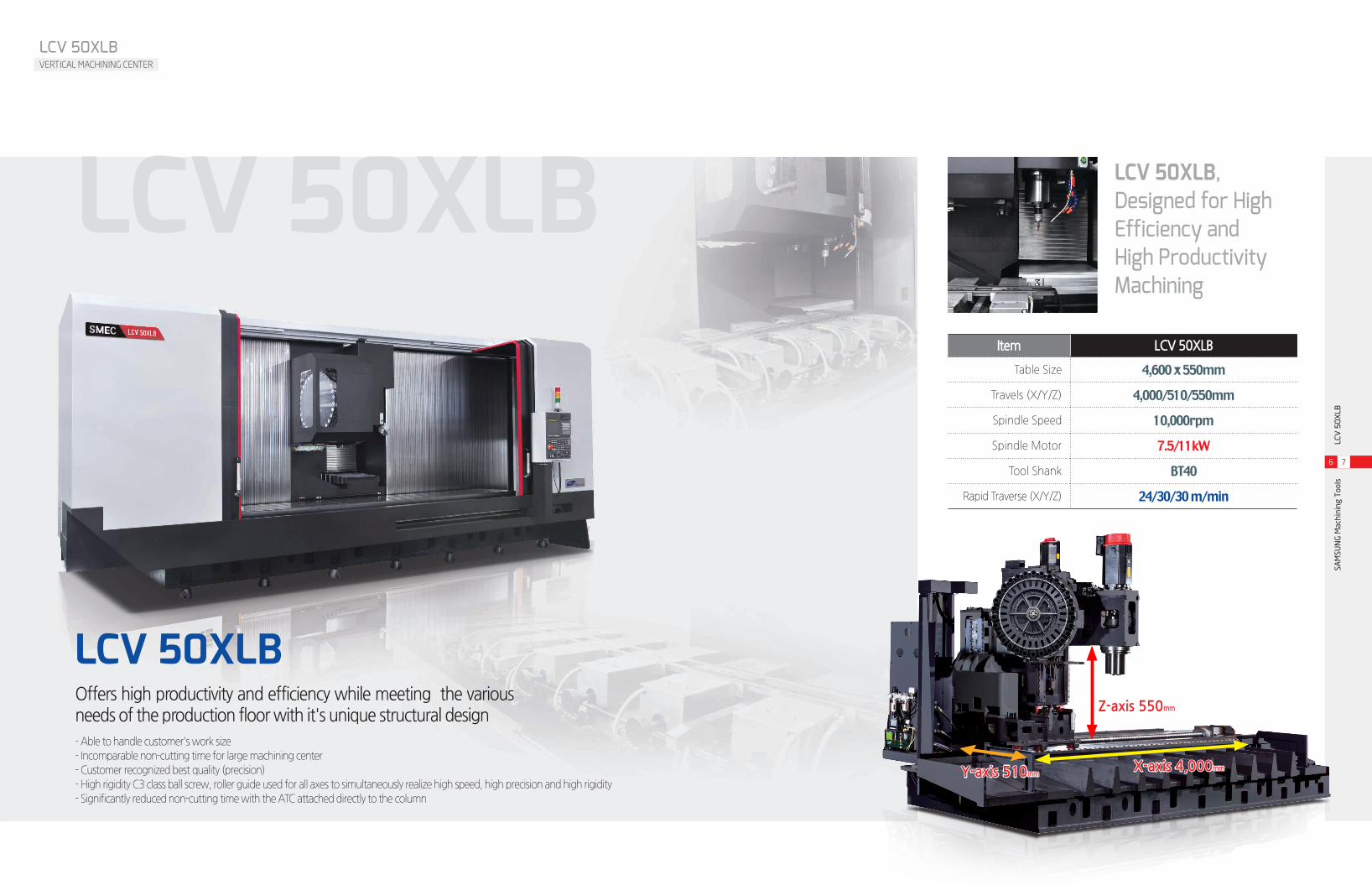
Item LCV 50XLB
Table Size 4,600 x 550mm
Travels (X/Y/Z) 4,000/510/550mm
Spindle Speed 10,000rpm
Spindle Motor 7.5/11kW
Tool Shank BT40
Rapid Traverse (X/Y/Z) 24/30/30 m/min
LCV 50XLBOffers high productivity and efficiency while meeting the various needs of the production floor with it's unique structural design
LCV 50XLB, Designed for High Efficiency and High Productivity Machining
LCV 50XLBVERTICAL MACHINING CENTER
- Able to handle customer's work size
- Incomparable non-cutting time for large machining center
- Customer recognized best quality (precision)
- High rigidity C3 class ball screw, roller guide used for all axes to simultaneously realize high speed, high precision and high rigidity
- Significantly reduced non-cutting time with the ATC attached directly to the column
Z-axis 550mm
X-axis 4,000mmY-axis 510mm
LCV 50XLB

SAM
SUN
G M
achi
ning
Too
lsLC
V 5
0XL
B
8 9
LCV 30LB/30XLB/50XLBVERTICAL MACHINING CENTER
Main Operation Panel
Mounted on a guide rail, the OP panel can be moved from
the right edge of the table to the very center, allowing the
operator to look closely at the workpiece.
FULL SPLASH GUARD(STD.)
The standard Full Splash Guard with front, left and right slide covers keeps the chips and coolant
contained near the table, preventing their discharge into the outside environment, simplifying chip
discharge.(LCV 50XLB)
LCV 50XLB
Spindle Power and Torque Diagram Unit : mm
2000 4000 6000 8000 100000
0
4
8
12
16
SPINDLE SPEED [min¯¹]
PO
WE
R [
KW
]
11kw
7.5kw
30Min, S3 60%Operating zone
ContinuousOperating zone
2000
1500
4000 6000 8000 100000
0
20
40
60
80
SPINDLE SPEED [min¯¹]
PO
WE
R [
N.m
]
30Min, S3 60%Operating zone
ContinuousOperating zone
MEMORY RANDOM Type Quick Tool Changer
Double Arm Swing Type offers the fastest tool
change time
Tool to Tool Time
1.5 sec (LCV 50XLB)
Oil Bath Cam Type (LCV 50XLB)
In general, BT30 sized machines use Drum Type tool changing. But due to the vibration from the
heavy head of Drum Types, SMEC implemented an self-developed high-speed CAM system.
30 ea (LCV 50XLB)
Tool Magazine
Servo motors are used to operate the ATC and MG,
ensuring problem-free high-speed ATC operation.
High speed magazine rotation helps reduce non-
cutting time.
Rapid Traverse(X/Y/Z)LCV 50XLB : 24/30/30 m/min
Table SizeLCV 50XLB : 4,600×550 mm
Motor power (Cont. / 30min)LCV 50XLB : 7.5/11 kW

SAM
SUN
G M
achi
ning
Too
lsLC
V 3
0LB
/30
XLB/
50XL
B
10 11
LCV 30LB/30XLB/50XLBVERTICAL MACHINING CENTER
X-Axis
Rapid Traverse Rate
In order to increase traverse rate, L/M Guides were used
for all the axes, to offer rapids not normally seen in large
machines. To ensure durability and quality assurance
during heavy-duty cutting, German-made Schneeberger
Roller Type LM Guides were used.
X축 이송
Y-Axis Travel
Moveable Column
With the workpiece fixed, the column
travels in the X and Y-axis and
machines, so even if the workpiece is
large and heavy, there is no overhang
of the X and Y axis, enabling precise
machining.
X-Axis Thermal Expansion Prevention
As long workpieces (in the X-Axis) are usually machined,
small changes in temperature changes the length of the
ballscrew on both ends. SMEC minimizes this change by
fixing both ends and applying pre-tension to the ballscrew.
Rapid Traverse(LCV 50XLB)
24/30/30 m/min·X-Axis Ball Screw Diameter
Ø63·X-Axis Feed Motor
6 kW
Rapid Traverse(when X-Axis Stroke is 4 meters)
26/48/48 m/min·X-Axis Ball Screw Diameter
Ø32 → Ø63·X-Axis Feed Motor
1.8 kW → 3 kW ※ When the X-Axis stroke is 4 meters,
the ball screw and motor are much
larger as presented above.
Servo Motor 1
- Power conversion via direct coupling (without using transfer medium)
- Minimized backlash during axis feed
Guide Way 2
- Improved speed, rigidity and durability
- Better wear resistance than BALL LM GUIDES, ensuring better
precision travel and extended machine lifetime
1
2

Unit : inch
SAM
SUN
G M
achi
ning
Too
lsLC
V 3
0LB
/30
XLB/
50XL
B
12 13
Machining Precision
Cable Chain
Smart One, Global OneLCV 30LB/30XLB/50XLBVERTICAL MACHINING CENTER
Unit : mm Machine Dimensions Unit : mm
LCV 30XLB
LCV 50XLB
6,656(FLOOR WIDTH)
6,150(MACHINE WIDTH)
5,950
520 166
650
1,100
1,750(HEIGHT OF S/GUARD)
2,535(MAX.MACHINE HEIGHT)
2,440(MAX.FOR HEIGHT)
2,132(MACHINE HEIGHT)
308
430
1,250.5
312 5121,918
2,742(MACHINE DEPTH)
890(TABLE HEIGHT)
330(Z AXIS STROKE)
350(Y AXIS STROKE) 1,505 252230
256 648(SIDE DOOR)
405
240
2,465(OP.BOX STROKE)
100
4,000 (X-AXIS ST/2) 4502,244
1,7592,226(DOOR OPEN) 2,226(DOOR OPEN) 1,381
286.78
2,806
920
700
200
510(Y-AXIS STROKE) 544.3 720.7
3,092.78(Machine Height)
37,952.05(Machine Width)
2,800(Machine Depth)3,489
1,055550(SIDE DOOR)3001,0178,969
ConditionsMachine LCV 50XLB
Material A 1050P
Tool Ø25×4T
Spindle Speed 1,500RPM
Cutting depth 0.1mm
Tool size Ø180
Feedrate 300m/min
Roundness
7.80㎛
20㎛
-80 500 1000 1500 2000 2500 3000 3500 4000
타겟(mm)
전체 데이타 출력 위치결정도
에러
량(㎛
)
-7
-6
-5
-4
-3
-2
-1
0
1
2
3
: 좌측이동 : 우측이동
■Roundness
■X-axis Positioning AccuracyComplete data output
Movement to left Movement to right
Positioning Accuracy
Target(mm)
ConditionsMeasured axis X-axis
Methodology Roundtrip
Position Accuracy
12㎛/4,000mm
※Measured X-axis ballscrew position accuracy.
All wires to the spindle and stranded wires to the OP Panel are
protected in the Cable Chain, improving the overall design while
protecting the wires from damage caused by repeated movement by
the OP Panel.
Cable Chain

•LEVEL BASE PLATES AND BOLTS
•COOLANT TANK
•TOOLS AND TOOL BOX
•SPLASH GUARD
•DATA SERVER (LCV 50XLB/420UL)
•AICC2 (LCV 50XLB/420UL)
•LIFT UP CHIP CONVEYOR
•SCREW CONVEYOR (FOR REAR TYPE CHIP CONVEYOR)
•3MPG
•DATA SERVER (LCV 30LB/XLB)
•AICC2 (LCV 30LB/XLB)
•T-SLOT TYPE TABLE
SAM
SUN
G M
achi
ning
Too
lsLC
V 3
0LB
/30
XLB/
50XL
B
14 15
Smart One, Global One
Machine Specification
Standard Accessories Optional Accessories
NC Specification (FANUC 0i-MD)
LCV 30LB/30XLB/50XLBVERTICAL MACHINING CENTER
Item LCV 30LB LCV 30XLB LCV 50XLB
Max. travel distance (X/Y/Z) mm 4,000/350/330 4,000/350/330 4,000/510/550
Distance from table surface to spindle nose mm 240 ~ 570 240 ~ 570 150 ~ 700
Distance from spindle center to column mm 397 397 675
Table size mm 2,200×400 4,130×400 4,600×550
Table surface M12 TAP M12 TAP M16 TAP
Spindle
Spindle speed min-1 10,000 10,000 10,000
Spindle taper NT40 NT40 NT40
Spindle bearing I.D. mm Ø50 Ø50 Ø70
Motor power (Cont./30min) kW 3.7/5.5 [5.5/7.5] 3.7/5.5 [5.5/7.5] 7.5/11
FeedrateRapid traverse (X/Y/Z) m/min 30/48/48 26/48/48 24/30/30
Cutting feedrate mm/min 1 ~ 10,000 1 ~ 10,000 1 ~ 10,000
ATC
Tool shank BT30 BT30 BT 40 / BBT 40
Magazine capacity 16 16 30
Tool changing time (T-T) sec 0.7 0.7 1.5
Max. tool length / weight kg 250 / 8 250 / 8 300 / 8
Max. tool dia. (adjacent empty) mm Ø90 (Ø110) Ø90 (Ø110) Ø90 (Ø140)
Power supply KVA 30 30 32
Floor space (L×W×H) mm 6,550×2,787×2,535 6,550×2,787×2,535 7,952×2,810×3,093
Machine weight kg 13,000 13,000 21,000
CNC system Fanuc 0i-MD Fanuc 0i-MD Fanuc 0i-MD
※Design and specifications subject to change without notice. [ ] : Option
Item Specification F 0i-MD
Controlled axis
Controlled axes X,Y,Z,(A,B)
Max. controlled axes 4(6) AXIS
Max. simultaneously controlled axes 4
Least input increment 0.001mm / 0.0001" ◯
Operation functions
Manual handle feed X1, X10, X100 ◯
Feed per minute G94 ◯
Feed per revolution G95 ◯
Interpolation functions
Linear Interpolation G01 ◯
Circular Interpolation G02, G03 ◯
Dwell G04 ◯
Cylindrical Interpolation G70.1 ◯
Reference Position Return G28 ◯
Reference Position Return Check G27 ◯
Feed functionRapid traverse feedrate override F0, 25%, 50%, 100% ◯
Feedrate override 0~200%
Spindle functionSpindle override ◯
Rigid tapping ◯
Tool functions
Tool function T4-Digt / T2-Digt ◯
Tool nose radius compensation G40 ~ G42 ◯
Tool offset pairs 400
Tool geometry / wear offset GEOMETRY & WEAR DATA ◯
Tool life management ◯
Tool path graphic display ◯
Automatic tool compensation ◯
Program input
Absolute / incremental programming ◯
Multiple repetitive cycle G70 ~ G76 ◯
Canned cycle G90, G92, G94 ◯
Inch / metric conversion G20 / G21 ◯
Program restart ◯
Retraction for rigid tapping ◯
Max. programmable dimension ±99999.999mm/±9999.9999" ◯
M function M3 digit ◯
Custom macro ◯
Canned cycle for drilling ◯
Direct drawing dimension programming ◯
Programmable data input G10 ◯
Optional block skip ◯
Workpiece coordinate system G52 ~ G59 ◯
Number of registerable programs 400EA
Setting and display
Help function ALARM & OPERATION DISPLAY ◯
Run hour / parts count display RUNNING TIME & PART NO. DISPLAY ◯
Spindle & servo load display SPINDLE & SERVO LOAD DISPLAY ◯
Self-diagnosis function ◯
Extended part program editing COPY,MOVE, CHANGE OF NC PROGRAM ◯
Display screenLCV 30LB/XLB : 8.4" color
LCV 50XLB/420UL : 10.4" color
Data input/outputMemory card input / output ◯
USB memory input / output ◯
Editing operation Part program storage size 512Kbyte(1280m) 1280M
Manual guide i Manual Guide I Opt.