lcls physics requirements document #€¦ · web view · 2009-06-12basic instrument design...
TRANSCRIPT

ENGINEERING SPECIFICATION DOCUMENT (ESD)
Doc. No.SP-391-000-29
LUSI SUB-SYSTEMX-Ray Correlation
SpectroscopyLUSI X-ray Correlation Spectroscopy (XCS) Instrument
Engineering Specification
Eric BongXCS Lead Engineer, Author Signature Date
Aymeric RobertXCS Scientist Signature Date
Darren MarshLCLS Quality Assurance Manager Signature Date
Tom FornekLUSI System Manager Signature Date
Revision Date Description of Changes Approved0 Initial Release
Table of Contents
ESD SP-391-000-85 Verify that this is the latest revision.1 of 18 Check for change orders or requests

Table of Contents............................................................................................21. Scope...........................................................................................................32. XCS Instrument Summary..........................................................................33. XCS Major Subsystems...............................................................................34. XCS Beamline Schematic............................................................................45. Interface Control Documents......................................................................66. Physics Requirements Documents..............................................................77. Engineering Specification Documents........................................................78. Supplemental Specifications and Requirements Documents.....................79. Project Management Control System (PMCS)............................................810. Basic Instrument Design Criteria.............................................................8
10.1. Hutch PPS Access State Criteria........................................................810.2. Basic Hardware Design Criteria.........................................................910.3. Basic X-ray beam parameters for mechanical design baseline..........910.4. Baseline Instrument Reconfiguration Procedure.............................10
11. Optical-Diagnostic Suites Support System Design Criteria....................1111.1. Materials...........................................................................................1211.2. Thermal Issues..................................................................................1311.3. Structural Issues...............................................................................13
12. Precision motion......................................................................................1313. Alignment/Fiducialization.......................................................................1314. Vacuum System Design Criteria.............................................................1315. Installation Criteria.................................................................................1516. Operations and Maintenance Criteria....................................................1517. Environmental Safety and Health Design Criteria.................................1518. Radiation Shielding Design Criteria.......................................................1519. Inspection, Testing and Commissioning.................................................1520. Quality Assurance Criteria......................................................................1621. Acronyms.................................................................................................16
ESD SP-391-001-29 XCS Instrument2 of 18

1. ScopeThis document is intended to consolidate all engineering requirements and specifications related to the LCLS-LUSI X-Ray Correlation Spectroscopy (XCS) instrument.
The XCS instrument project is managed under LUSI Work Breakdown Structure (WBS) section 1.4. Only items specifically described in WBS 1.4 will be dealt with in detail.
Elements managed outside of WBS 1.4 will be addressed only insofar as their inclusion provides a more complete understanding of XCS WBS 1.4 requirements.
Numerous documents providing guidance and definition for the design and engineering exist. This ESD is to serve as a “roadmap” to all documents related to the execution of the XCS engineering and design effort. Those supporting documents are referenced in the appropriate section of this document.
2. XCS Instrument SummaryThe primary purpose of the X-Ray Correlation Spectroscopy (XCS) instrument is to enable the study of dynamic phenomena in condensed matter systems down to nano-metric scale lengths. The instrument must provide sufficient versatility to perform XCS on samples using Small Angle X-Ray Scattering (SAXS), Wide Angle X-Ray Scattering (WAXS), or Grazing Incidence techniques.
The XCS instrument may operate in either Sequential mode, limited by the beam repetition rate (120 Hz) or in Ultrafast Mode where the beam is split and recombined after a time delay is introduced in one of the split paths. The Ultrafast mode allows dynamic phenomena investigation on the time scales from several nanoseconds down to 200 femptoseconds.
More detail regarding use and performance of the instrument may be found in Physics Requirements Documents SP-391-001-35-0, Physics Requirements for the XCS instrument.
ESD SP-391-001-29 XCS Instrument3 of 18
The XCS instrument shall have portions of its hardware located in both the X-ray Transport Tunnel (XRT) and Hutch 4 (H4) of the LCLS Far Experimental Hall (FEH).
3. XCS Major SubsystemsThe XCS instrument is comprised of seven subsystems:
1. The Monochromator selects a narrow bandwidth about a particular selected wavelength desired to illuminate the sample. Two monochromators may be employed. The first may be a zero offset, wide dynamic range unit covering the entire operating range of the LCLS. The second monochromater would be a large offset design which may be designed to operate in a selected range of energy less than the full range of the LCLS. The inclusion of a zero offset Monochromator could result in earlier use of the XCS instrument. The Monochromator(s) are to be provided by the Diagnostics & Common Optics (DCO) branch of the LUSI project (WBS-1.5).
2. The Split & Delay unit provides the capability of exploring dynamics in time regimes less than the repetition rate of the LCLS. The first split and delay unit would be provided by Deutsches Elektronen Synchrotron (DESY) using a Memorandum of Understanding between SLAC and DESY. The DESY unit operates at a single energy. Space will be provided in the instrument design to upgrade the Split and Delay capability to a tunable range of energies.
3. The XCS Diffractometer provides orientation of the sample in position and angle relative to the photon beam. The diffractometer will allow the sample to be positioned to perform experiments in SAXS, WAXS and grazing incidence configurations. The diffractometer is contained in XCS WBS 1.4.4.
4. The Large Angle Detector Mover positions the detector relative to the sample mounted on the XCS Diffractometer. The mover may position the detector to measure scattered signals in either SAXS, WAXS or grazing incidence configurations. The Large Angle Detector Mover is contained in XCS WBS 1.4.4.
ESD SP-391-001-29 XCS Instrument4 of 18

5. The XCS Detector, mounted on the Large Angle Mover, measures the number of photons in the speckle pattern using a pixel array. The detector will be developed at Brookhaven National Laboratory (BNL) under an MOU. The detector is funded through XCS WBS 1.4.3 but is managed as a separate sub-project.
6. The diagnostics and common optics suite is used to analyze and optimize the X-ray beam properties. These components are located in both the XRT and FEH H4 and consist of a suite of X-ray optic and diagnostic components that are common with the other instruments developed by LUSI as well as XCS specific hardware, (i.e. Large Offset Monochromator). The suite includes slits, focusing optics, attenuators, pulse pickers, intensity monitors and position detectors. The diagnostics and common optics components are provided to XCS by DCO WBS 1.5.
7. The vacuum system will create and support an ultra-high vacuum environment along the entire XCS beamline. Included in this subsystem are vacuum equipment, hardware, bellows, spools and vacuum supports.
In addition to the included components the design of the instrument will provide the capability to upgrade and/or insert additional components such as the following. The diffractometer will be able to manipulate a sample environment provided by a researcher. The space allocated for the split and delay unit will be adequate to accommodate an upgraded split and delay. The hutch floor plan will be large enough to accommodate a future long-arm small-angle detector and vacuum transport. The wide angle mover should be reconfigurable to shorter arm lengths. The diffractometer must be removable to accommodate large sample environments and alternative sample positioning apparatus.
4. XCS Beam-Line SchematicFigure1 - 3 show in schematic form, the XCS components; all are LUSI CD-4C deliverables.
ESD SP-391-001-29 XCS Instrument5 of 18
H4 RegionXRT Region

Figure 1: XCS Beamline Regions and Vacuum Sections
Figure 2: XCS XRT Region and Components
ESD SP-391-001-29 XCS Instrument6 of 18

Figure 3: XCS Hutch 4 Region and Components
5. Interface Control Documents
The documents identified in Table 1 define the interface responsibilities between groups working in support of XCS Instrument.
Document Name Document Number
X-ray End Stations to Conventional Facilities
LCLS 1.1-509
Vacuum controls to Vacuum Mechanical LCLS 1.1-510XES to LUSI ICD LCLS 1.1-523XES Photon Controls to Electron Beam Controls ICD
LCLS 1.1-516
XCS – LUSI Controls ICD 391-001-25LUSI to XTOD 391-000-05XCS - DCO ICD TBDXCS - CXI ICD TBD
ESD SP-391-001-29 XCS Instrument7 of 18

XCS Detector to XCS Mover ICD TBDTable 1: XCS Interface Control Documents
6. Physics Requirements Documents
The documents identified in Table 2 define the physics requirements for XCS Instrument.
Document Name Document Number
XCS Instrument SP-391-001-35XCS Diffractometer system SP-391-001-32XCS Wide Angle Detector Stage SP-391-001-33XCS 2D Detector SP-391-000-98XCS Instrument Start-up Plan SP-391-001-17X-Ray Systems Operational Modes LCLS 1.6-009
Table 2: XCS Physics Requirements Documents
7. Engineering Specification Documents
The documents identified in Table 2 define the engineering specifications for XCS Instrument.
Document Name Document Number
XCS Instrument Specification SP-391-001-29XCS Diffractometer SP-391-001-30XCS Detector Mover SP-391-001-31LUSI Controls and Data System SP-391-000-03Engineering Spec for the XCS Instrument Controls
SP-391-001-24
Data Acquisition Specs for the XCS Experiment
SP-391-001-26
Engineering Specifications for Hutch 4 of the FEH
LCLS 1.9-112
Engineering Spec for the XCS Room of the FEH
LCLS 1.9-115
Engineering Spec for the Common Room of the FEH
LCLS 1.9-116
Table 2: XCS Engineering Specifications Documents
ESD SP-391-001-29 XCS Instrument8 of 18

8. Supplemental Specifications and Requirements Documents
The documents identified in Table 3 define the supplemental specifications and requirements for the XCS Instrument.
Document Name Document Number
LCLS Vacuum Requirements LCLS 1.1-302Vacuum Controls Requirements LCLS 1.1-326Vacuum Controls Reqmts for XTOD and XES
LCLS 1.1-328
LUSI Data Management System SP-391-000-06LUSI Mechanical Design Standards DS-392-000-36LUSI Quality Implementation Procedure PM-391-000-
01Multi-Port Vac Cham Assys for Exp. Stations
PS-391-001-47
Table 3: XCS Supplemental Specifications and Requirements
9. Project Management Control System (PMCS)
The XCS Instrument schedule and cost estimate will be defined and controlled by the LCLS procedures listed in Table 4.
Document Name Document Number
Earned Value Management System Description
LCLS 1.1-015
CA and WP Planning Procedure LCLS 1.1-018Change Control Procedure LCLS 1.1-019Project Schedule Procedure LCLS 1.1-020Cost Estimating Procedure LCLS 1.1-021Monthly Status and Reporting Procedure LCLS 1.1-022WBS Structure PM-391-000-
96WBS Dictionary PM-391-001-
12Risk Registry PM-391-001-
11LCLS Basis of Estimate Methodology LCLS 1.1-100LCLS Design Review Guidelines LCLS 1.1-324LCLS Collaboration Drawing Control LCLS 1.1-320Subcontract Management Procedure LCLS 1.1-023
ESD SP-391-001-29 XCS Instrument9 of 18
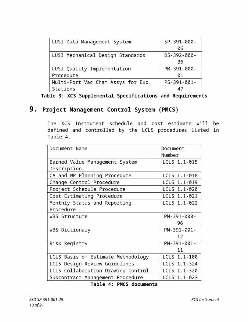
Table 4: PMCS documents
Additional project management control information may be found in the LUSI PMCS SharePoint site including current cost performance reports and detailed cost estimates.
10. Basic Instrument Design Criteria
10.1. Hutch PPS Access State CriteriaNo access to the FEH H4 hutch shall be permitted unless the upstream PPS photon stopper (located in the XRT) is in the closed position. Access is allowed while beam is delivered through evacuated pass-through pipes to downstream hutches. PPS access requirements are discussed in further detail in LCLS ESD 1.1-310, LCLS Personnel Protection System Requirements.
10.2. Basic Hardware Design CriteriaThe design service life of the XCS hardware is at least 10 years.
All hardware downstream of the Monochromator will be capable of operating in the XCS beamline or in the CXI beamline.
There shall be a heating system and an air conditioning system capable of maintaining the operational hutch temperature at 72 ±1 Fahrenheit. Time stability at any given point is required while spatial fluctuations greater than 1 F are allowable.
The XCS hardware will support data acquisition at operational temperature/tolerance.
The XCS hardware will accommodate extreme temperature/tolerance without permanent damage (~32 F - 120F).
All hardware will return to nominal position when hutch temperature returns to operational specifications. Minimal realignment may be required if equipment experiences extreme temperature excursions.
No extraordinary hutch humidity is anticipated.
The nominal experiment duration is on the order of several days. An experiment is defined as use of the FEH H4 hardware during which
ESD SP-391-001-29 XCS Instrument10 of 18

the hardware configuration is not substantially modified or reconfigured.
All tasks to reconfigure the XCS hardware will be within the competency of a typical SLAC mechanical technician. Design of the hardware will accommodate rapid reconfiguration of the instrument. Major reconfiguration could require precision alignment or expert technician effort.
10.3. Basic X-ray beam parameters for mechanical design baselineThe nominal height of the X-ray beam is 1.4 meter above the hutch and XRT floor. Local coordinate systems relative to the X-Ray beam (and LCLS coordinate system) will be established for the XRT and Hutch 4 for local beamline layout. See LUSI Mechanical Design Standards DS-392-000-36.
The actual, nominal, global position of the X-ray beam will be known before XCS hardware is installed in the hutch. Any difference between design beam location and actual beam location will be addressed prior to installation.
The nominal X-ray beam position will drift to such an extent that repositioning-alignment of XCS hardware will be required at every experiment reconfiguration. This includes X-ray optics, sample chamber and detector. Any repositioning should be accomplished using typical SLAC mechanical technicians’ competency.
The X-ray beam will maintain precise position throughout the course of each experiment (on the order of several days) to the extent that realignment during the experiment will not be necessary.
10.4. Instrument ReconfigurationXCS Instrument hardware will be designed to accommodate reconfiguration of the instrument to the specific needs of an experimenter. Common foreseen configuration modifications are as follows:
1. Placement of sample environment
2. Removal/Replacement of Diffractometer
3. Alignment of FEH H4 beamline components
ESD SP-391-001-29 XCS Instrument11 of 18
4. Realignment of large angle detector mover
5. Change operation from XCS to CXI beamline, or CXI to XCS beamline
Standard procedures for common configuration changes must be established and maintained. Access to common procedures must be made available to prospective experimenters. The design of the instrument components should not preclude unforeseen configuration modifications.
11. Diagnostics & Common Optics EquipmentDetailed specifications of each Diagnostics & Commoon Optics device are maintained by the DCO group. In general, design criteria for the position stability of the support structures for the diagnostics & optical elements are as follows.
Prioritized design criteria:
1. All translating beamline elements must be under positive control at all times.
a. All elements will have fixed (immovable) hard stops defining motion extents
b. Human intervention will not be required to confine elements within their intended range of motion.
2. Stable relative optical–diagnostic element position (i.e., elements with respect to other).
a. Goal: < 5 micron (±2.5) relative position stability.b. Assumed sources of deviation:
i. Thermal gradients within supportsii. Loads across bellows due to remote commanded
component motionsiii. Dynamic response to cyclic input loads
3. Stable absolute optic-diagnostic suite position (i.e., elements as a unit in global space)
a. Goal: < 15 micron (±7.5) with 2 (±1) F variationb. Assumed sources of deviation:
i. Gross bulk thermal variation
ESD SP-391-001-29 XCS Instrument12 of 18

ii. Dynamic response to cyclic input loadsiii. Unintended redundant loads
c. Slits to serve as position datum for optic-diagnostic suited. Assumes use of invar component fine align supports
4. High repeatability of translation hardware (i.e., moving between positions 1 and 2)
a. Goal: <25 micron horizontali. Assumed sources of deviation:
ii. Unintended redundant loadsiii. Improper restraint load inputiv. Hard strike while contacting stop
b. Goal: < 15 micron verticali. Same as 3 above
5. Minimize adjacent component motion due to alignment/bellows /external loads
a. Goal: <2 micronb. Assumed sources of deviation:
i. Force couples through support structure from remote command motions
6. Intuitive and clearly marked methods of traversing beamline components.
7. Absolute alignment of support structure
a. Goal: < 200 micron
11.1. MaterialsUse of materials with low coefficients of thermal expansion is highly desirable to reduce thermal motion
Use of materials with low thermal diffusivity to limit the displacement effects of short-term temperature excursions is highly desirable
11.2. Thermal IssuesAll supports for XCS will have deterministic constraints fully compliant to thermal variations or gradients. Thermal variations or gradients will not create redundant loads on the support system.
ESD SP-391-001-29 XCS Instrument13 of 18

11.3. Structural IssuesAll support system hardware will be engineered to be compliant with SLAC-I-720-0A24E-002-R002, Seismic Design Specification for Buildings, Structures, Equipment, and Systems.
12. Precision motionMotion control elements will be specified such that the requirements of section 11 are achieved.
When consistent with physics and engineering requirements manual control of translation hardware is acceptable, i.e., no need for remotely operated motor control.
A high level of repeatability when reconfiguring the instrument between experiments is desirable. All components to be mounted on the support structures will have their own fine alignment supports.
The nominal distance from the center of the diffractometer to the wide angle detector is 8 m. The wide angle detector must be capable of covering at least 0° to 55°.
13. Alignment/FiducializationThe X-ray optic-diagnostic support system hardware will not be fiducialized for precision alignment. Support system hardware will be located in the hutch via measurements taken from nominal features/surfaces/edges.
Individual optic-diagnostic components will be fiducialized and precisely aligned after mounted on the support structures.
14. Vacuum System Design CriteriaIn both the XRT and FEH H4, the average beamline pressure shall be 10-7 Torr or better.
A Residual Gas Analysis (RGA) scan shall be performed prior to opening the XCS beamline to the LCLS XTOD transport line. The predominant gas component should be hydrogen and be at least 60% of the total pressure. The RGA scan should exhibit no evidence of air or other leaks in the system and masses greater than 28 AMU shall be less than 10% of the total pressure. The sum of components
ESD SP-391-001-29 XCS Instrument14 of 18

at mass locations 39, 41, 43, 45 and greater shall total less than 1 x 10-11 (N2 equivalent)
There shall be no evidence of leaks (external, virtual, etc.) in the vacuum system, air or other.
All sections between valves will have a minimum of one gauge set providing pressure sensitivity from atmosphere to 10-9 Torr.
All seals nominally to atmosphere will be all metal construction. Non-metallic seals in normally open valves are acceptable. Normally closed (vent/purge) valves will be all metal seal types.
All sections between valves will have a minimum of one vent/purge valve.
All sections between valves shall have a minimum of one pressure burst disk.
Base pressure at vacuum pumps will be consistent with manufactures recommendations for 10-year life expectancy.
Dry pumping systems shall be used to minimize contamination.
All lubricants, cutting fluids, etc., used in manufacturing shall be "sulfur-free". Reference SLAC document No. SC-700-866-47 for a complete list of approved machining lubricants. The use of sanding discs, abrasive paper or grinding wheels is typically prohibited. In special circumstances good vacuum practices should be followed when grinding and polishing is required. This process shall be reviewed and approved by the engineer for its vacuum compatibility.
All parts and subassemblies shall be cleaned for UHV. Once parts are cleaned for vacuum they are to be handled only with clean latex or nitrile gloves. All components that cannot be made vacuum tight and purged with dry nitrogen shall be wrapped in SLAC approved lint free paper and Aluminum foil or sealed in a purpose approved vacuum container. Components should only be vented, unwrapped or otherwise exposed in a clean room environment. This includes all piece parts, subassemblies and completed instruments. For storage or transportation, place in clean sealed vacuum grade plastic bag that has been back-filled with nitrogen.
ESD SP-391-001-29 XCS Instrument15 of 18

15. Installation CriteriaInstallation requirements will be addressed in the design phase. Access to the 1-ton crane will be factored into the design of components. Building size and access requirements will be considered for large components. Further installation requirements for the XCS instrument will be established during detail design.
16. Operations and Maintenance CriteriaThe XCS instrument shall be designed so that equipment failure or the need for maintenance does not impact the operations of the other LCLS/LUSI instruments.
The reliability and maintenance requirements for each component are described in the individual Physics Requirement Documents and Engineering Specifications Documents associated with each component.
The XCS instrument shall be designed for maintenance operations within a reasonable amount of shutdown time. Component access and handling will be provided in the component design.
17. Environmental Safety and Health Design CriteriaAll hardware designs will be approved via the LCLS Design Review Guidelines, LCLS ESD # 1.1-324)
The implementation of the LCLS Project Environment, Safety and Health Plan, LCLS PMD # 1.1-011 and the LUSI Hazards Analysis Report, PM-391-001-34 will be an integral part of the design and review process for the XCS Instrument. Special attention will be focused on the core functions of the Integrated Safety and Management System (ISMS) in each design reviews.
18. Radiation Shielding Design CriteriaRadiation physics simulations of scattering sources in FEH H4 will be completed by the SLAC Radiation Physics Group. Local or area shielding will be implemented as required to achieve hutch accessibility to support the requirements of section 10 of this document.
ESD SP-391-001-29 XCS Instrument16 of 18
19. Inspection, Testing and CommissioningFull inspection of piece parts, for geometric and material property acceptance will be required. Written reports of inspections will become an element of the component pedigree and archived in a LUSI component database.
Sub-assembly and component level testing will be conducted to establish compliance with engineering specifications and physics requirements. Testing will include, but not be limited to, any required motion accuracy and precision, controls hardware (limit switch, position encoders, etc) performance, vacuum performance, support stability and any safety system performance (interlock, safety covers, etc). System wide integration testing (without X-ray beam) will be conducted to validate component level tests and insure seamless operation of the instrument.
Commissioning of the XCS instrument with beam is not a part of the LUSI MIE Project. The LUSI project provides design, procurement, construction, installation and testing without beam. A start-up test plan, operating procedures and training needed for commissioning (not user operation) of the XCS instrument will be provided. Construction completion shall be confirmed by an Instrument Readiness Review and resolution of all pre-startup (required before receiving beam) issues generated by the review. All testing shall be appropriately documented.
20. Quality Assurance CriteriaThe implementation of the LUSI Quality Implementation Procedure (QIP), PM-391-000-01 will be an integral part of the design and review process for the XCS Instrument. All activities associated with the XCS instrument will be conducted in accordance with accepted engineering standards and practices. Good engineering practices imbedded within the established design process will ensure safe and reliable operation of the instrument and will mitigate conditions that pose a threat to success. In all cases, consensus standards will be used to accomplish design activities. Where standards do not exist to adequately control an activity, appropriate administrative controls will be considered and created if required.
ESD SP-391-001-29 XCS Instrument17 of 18

Thoughtfully derived and properly “graded” controls for design, manufacturing, installation, testing, and operation of the XCS instrument will be established before execution of each of these activities.
Additional controls will only be proposed in cases where they enhance the probability of success. Successful quality assurance (QA) program performance will be verified through validation activities such as design reviews, surveillance activities, inspections, tests, and readiness reviews.
A list of drawings will be developed during detailed design.
21. AcronymsXCS: X-Ray photon Correlation SpectroscopyESD: Engineering Specifications DocumentFEH: Far Experimental HallH4: Hutch 4LCLS: Linear Coherent Light SourceLUSI: LCLS Ultra-fast Science InstrumentationMIE: Major Item of EquipmentPRD: Physics Requirements DocumentQA: Quality AssuranceUHV: Ultra High VacuumXRT: X-Ray Transport tunnel
ESD SP-391-001-29 XCS Instrument18 of 18