lcls front end enclosure pps engineering specification · lcls front end enclosure pps engineering...
TRANSCRIPT

LCLS Front End Enclosure PPS Engineering Specification DCO No. Released By: Effective Date Document No. Rev.
Safety Systems Section 0044 Uncontrolled Copy 04 May 09 CD-SS-PPS-06-11-03 01
Printed copies of this document must be verified as being current prior to use by checking the effective date on the Safety Systems Document Master List.
SLAC National Accelerator Laboratory Page 1 of 22
LCLS Front End Enclosure PPS Engineering Specification
Table of Contents 1.0 Introduction................................................................................................................... 2 2.0 General Information...................................................................................................... 2
2.1 Technical Basis Document ....................................................................................... 2 2.2 Passive Hazard Abatement ....................................................................................... 2 2.3 Engineering Controls for Hazards ............................................................................ 2
3.0 PPS Theory of Operation .............................................................................................. 3 3.1 Access Control Interlocks ......................................................................................... 3 3.2 Three-State Access Control System.......................................................................... 3 3.3 Keybank .................................................................................................................... 3 3.4 Outer Doors and Inner Gates .................................................................................... 3 3.5 Emergency Entry/Exit Provisions............................................................................. 4 3.6 Emergency Off Switches .......................................................................................... 4 3.7 Search Preset and Reset ............................................................................................ 4 3.8 Audio/Visual Warnings ............................................................................................ 5 3.9 Warning Lights and Signs......................................................................................... 5 3.10 FEE Stoppers ............................................................................................................ 5 3.11 Burn Through Monitors (BTM)................................................................................ 6 3.12 Beam Shut Off Ion Chambers (BSOICs).................................................................. 6 3.13 LCLS Security Loop................................................................................................. 6
4.0 Hardware....................................................................................................................... 7 4.1 General Hardware ..................................................................................................... 7 4.2 PPS Architecture....................................................................................................... 7 4.3 Programmable Logic Controllers (PLCs) ................................................................. 8
5.0 Appendix..................................................................................................................... 11 5.1 Appendix A. FEE PPS Component List ................................................................. 11 5.2 Appendix B. FEE Boolean Expressions ................................................................. 11 5.3 Appendix C. PLC Block Diagram .......................................................................... 11 5.4 Appendix D. Failure Analysis of Allen-Bradley PLC Functions ........................... 11 5.1 Appendix A. FEE PPS Component List ................................................................ 12 5.2 Appendix B. FEE Boolean Expressions ................................................................. 14 5.3 Appendix C. PLC Block Diagram .......................................................................... 18 5.4 Appendix D. Failure Analysis of Allen-Bradley PLC Functions ........................... 19
6.0 Revision History ......................................................................................................... 22
LCLS Front End Enclosure PPS Engineering Specification DCO No. Released By: Effective Date Document No. Rev.
Safety Systems Section 0044 Uncontrolled Copy 04 May 09 CD-SS-PPS-06-11-03 01
Printed copies of this document must be verified as being current prior to use by checking the effective date on the Safety Systems Document Master List.
SLAC National Accelerator Laboratory Page 2 of 22
1.0 Introduction
The LCLS Front End Enclosure (FEE) lies between the east end of the Beam Dump and the west end of the Near Experimental Hall (NEH). The electron beam stops at the Beam Dump and only the photon beam is present in the FEE and NEH.
After applying passive hazard abatement controls an engineered protection system was deemed to be necessary. The FEE is a shielded housing with a single entrance from the NEH. This entrance uses the same PPS hardware and protocol employed in similar PPS areas at SLAC.
2.0 General Information
2.1 Technical Basis Document
The Radiation Safety Systems Technical Basis Document (SLAC-I-720-0A05Z-002) is the guideline for designing the Personnel Protection System.
2.2 Passive Hazard Abatement
Shielding has been calculated and is installed in the housing between the FEE and the NEH.
All Electrical Hazards exceeding 50 volts or 10 joules in the FEE will be covered.
2.3 Engineering Controls for Hazards
The source of prompt radiation is an electron beam from the LINAC. The LINAC beam is generated by three guns, the polarized and thermionic guns in CID and the photo-electron gun in the LCLS injector vault. The electron beam is accelerated from RF produced by klystrons located in the LINAC. The klystrons are powered by sixteen Variable Voltage Supplies (VVS) also located in the LINAC. These sources of prompt radiation are interlocked to the LINAC PPS.
Two stoppers, located in LCLS Beam Dump, provide protection to personnel inside the FEE PPS area from the LINAC beam. These stoppers require redundant PPS permits from the FEE PPS for the stoppers to be extracted or turned on. The stoppers provide redundant IN/OFF status to the FEE PPS.
BSOICs (Beam Shut Off Ion Chambers) will be installed in the Front End Enclosure adjacent to the Beam Dump shielding to detect radiation. A BSOIC consists of an electrometer and an ion chamber for radiation detection. The BSOIC is not a redundant device. The BSOIC is interlocked to the LCLS Undulator PPS stopper permits which inhibits the electron beam from reaching the undulator.
LCLS Front End Enclosure PPS Engineering Specification DCO No. Released By: Effective Date Document No. Rev.
Safety Systems Section 0044 Uncontrolled Copy 04 May 09 CD-SS-PPS-06-11-03 01
Printed copies of this document must be verified as being current prior to use by checking the effective date on the Safety Systems Document Master List.
SLAC National Accelerator Laboratory Page 3 of 22
3.0 PPS Theory of Operation
3.1 Access Control Interlocks
The FEE is interlocked with four primary interlock devices that maintain the safety of the area. These devices are the position micro switches (for doors and gates), the keybank, Emergency Entry/Exit devices, and the Emergency Off Switches. These devices are considered to be the primary interlocks because they are the only devices that will inhibit the beam locally with human intervention. Every PPS area is equipped with these four devices.
The primary interlock devices interact with two circuits, the interlock complete circuit and the search reset circuit. All interlock switches must be closed for these circuits to be complete or reset. While some devices in the search reset circuit may be bypassed in Controlled Access to allow access to a PPS area without losing the search, the interlock complete circuit is never bypassed.
3.2 Three-State Access Control System
The FEE has a three-state access control system. The three access states are Permitted Access, Controlled Access and No Access. Bailing from No Access to Controlled Access or between Permitted Access and Controlled Access is allowed when the FEE stoppers are reporting OFF/IN status and the keybank is complete. Bailing between Controlled Access and No Access is allowed when the area has been searched and secured and all FEE interlock devices are reset. In No Access the search is lost when any interlock device changes state.
3.3 Keybank
The access control system has a keybank to provide tokens to personnel accessing the FEE housing. The keybank contains redundant micro switches that sense the keybank door, the key release mechanism, and keybank complete. Keybank keys are released by an operator in MCC. The keybank may only release tokens in Controlled Access when the LCLS FEE stoppers are reporting IN status. No changes in access state are allowed when the keybank is open, during the process of releasing keys, or when tokens are missing.
3.4 Outer Doors and Inner Gates
The entry module into the FEE has an outer double door (left and right) and an inner double gate (left and right). The doors and gates are interlocked with redundant limit switches.
The inner gates are not locked and have passive knob sets to keep them closed when the area is in No Access. The right outer door is locked with a magnetic

LCLS Front End Enclosure PPS Engineering Specification DCO No. Released By: Effective Date Document No. Rev.
Safety Systems Section 0044 Uncontrolled Copy 04 May 09 CD-SS-PPS-06-11-03 01
Printed copies of this document must be verified as being current prior to use by checking the effective date on the Safety Systems Document Master List.
SLAC National Accelerator Laboratory Page 4 of 22
lock (Magnalock) when the FEE is in Controlled Access or No Access. In Permitted Access the Magnalock is de-energized. The left outer door is for equipment access and is locked from the inside with manual slide bolts.
Access to the FEE housing is attained in Controlled Access by obtaining a Keybank key. The key is inserted into a Door Release Keyswitch located next to the right door. The Magnalock is de-energized with simultaneous commands from the Door Release Keyswitch and a door release command from an operator in MCC. Door release commands are inhibited in No Access.
3.5 Emergency Entry/Exit Provisions
In an emergency the Magnalock may be defeated by an Emergency Entry/Exit (E/E) device located near the right door. Activation of the E/E device causes a loss of the interlock summary as well as a loss of the search preset and reset. The E/E status is a latched signal that can only be reset in Controlled Access.
3.6 Emergency Off Switches
Emergency Off switches are placed in both the entryway and hallway at approximately fifty foot intervals. One Emergency Off switch is located in the Electronics Annex which is inside the radiological housing. The Emergency Off summary status is a latched signal that can only be reset in Controlled Access. The loss of the Emergency Off summary in Permitted or Controlled Access causes a loss of the interlock summary. A loss of the Emergency Off summary in No Access causes a loss of the interlock summary as well as a loss of the search preset and reset.
3.7 Search Preset and Reset
Searching the FEE is facilitated by the use of two Search Preset keyswitches inside the FEE housing, and a Search Reset keyswitch outside the entry door. Search Preset and Search Reset are latched status signals that may only be reset in Controlled Access.
After the Search Preset is set, the Search Reset may be obtained when all interlocks are complete. The interlocks that must be complete include the emergency off switches, the emergency entry and exit devices, all door and gate micro switches, and the keybank.
When the area is in Controlled Access and the search has been completed, the search reset circuit ignores the interlocks for the entry module keybank, the inner gates and the emergency off switches. For normal access entries an operator may temporarily bypass the outer door position micro switches with the Door Interlock Bypass (DIB) circuit. In Controlled Access the search is lost if the interlocks for the emergency entry or exit are activated or the outer

LCLS Front End Enclosure PPS Engineering Specification DCO No. Released By: Effective Date Document No. Rev.
Safety Systems Section 0044 Uncontrolled Copy 04 May 09 CD-SS-PPS-06-11-03 01
Printed copies of this document must be verified as being current prior to use by checking the effective date on the Safety Systems Document Master List.
SLAC National Accelerator Laboratory Page 5 of 22
door is opened. The outer door may be opened in Controlled Access without losing the search with the use of the DIB circuit as noted above.
3.8 Audio/Visual Warnings
After the search is complete and all interlocks have been reset the FEE housing may be set to No Access.
When the FEE is set to No Access the overhead fluorescent lights will flash and an audio announcement will play for two minutes. The audio announcement is a klaxon followed by a female voice stating, “Attention! Attention! The FEE housing is closed for beam operation. Push the nearest emergency off button and call extension two-one-five-one immediately!” After two minutes of audio/visual warning the lights are extinguished and the audio is silenced.
3.9 Warning Lights and Signs
The access module has posted warnings to indicate that the FEE enclosure is a radiological area. An annunciator sign above the outer door indicates the current access state. A Yellow/Magenta light indicates the safe/running status of the FEE enclosure. The magenta light will be lit when the enclosure has been searched and is in No Access. The magenta light will flash when the LCLS FEE stoppers do not redundantly report IN status. If the magenta light is neither on nor flashing then the yellow light will be lit.
3.10 FEE Stoppers
Photon beam is prevented from entering the FEE by stoppers ST-1, ST-2 located in the LCLS Beam Dump. The LCLS FEE stopper control chassis contains an inhibit keyswitch, stopper permit status and IN/OUT status of the individual stoppers. The LCLS FEE stopper chassis receives redundant stopper permissive signals when FEE is in No Access, the audio/visual warning is complete, the BSOIC in hutch 1 is OK and the BTM chassis summary is OK
The stoppers are also interfaced to the LCLS Security Loop which inhibits the Undulator stoppers when the loop is interrupted by a stopper security fault. The loop is complete when all stoppers are IN or the LCLS FEE stopper permissive signals are present and is faulted when the stoppers are not reporting IN in the absence of a stopper permissive.
LCLS Front End Enclosure PPS Engineering Specification DCO No. Released By: Effective Date Document No. Rev.
Safety Systems Section 0044 Uncontrolled Copy 04 May 09 CD-SS-PPS-06-11-03 01
Printed copies of this document must be verified as being current prior to use by checking the effective date on the Safety Systems Document Master List.
SLAC National Accelerator Laboratory Page 6 of 22
3.11 Burn Through Monitors (BTM)
There are three BTM associated with the FEE beamline. Each BTM is pressurized and redundantly sensed with pressure switches. The BTM are interlocked to the LCLS Security Loop.
If nitrogen is used, the reserve capacity of the nitrogen supply bottle will be sensed, but not interlocked to the LCLS Security Loop. If the supply pressure drops below approximately 500 psi an alarm will sound on the MCC Primary Annunciator Warning Panel.
A BTM fault is a catastrophic failure that must be repaired before the LCLS Security Loop can be reset. Repair includes, but is not limited to, replacing the nitrogen supply bottle.
3.12 Beam Shut Off Ion Chambers (BSOICs)
BSOICs will be installed inside the Front End Enclosure adjacent to the Beam Dump shielding to detect radiation. A BSOIC consists of an electrometer and an ion chamber for radiation detection. The BSOIC is not a redundant device. The BSOIC is part of the Undulator PPS and will not be interlocked to the LCLS Security Loop.
BSOIC faults will inhibit stoppers ST-1, ST-2 and the BTH stoppers ST-60, ST-61 and D2. When a BSOIC fault occurs BTH stoppers are inhibited from being removed while retaining their permit status. This provision maintains the state of the 30-MCC security loop and does not interrupt VVS permits.
The BSOIC inside the FEE, that monitors radiation from the LCLS Dump enclosure, will be bypassed when the FEE is in No Access and secure.
3.13 LCLS Security Loop
The LCLS Security Loop is a 17mA constant current loop used to monitor the security of the PPS areas downstream of the Undulator stoppers ST-60, ST-61 and D2. Undulator stopper permissive signals are generated when the LCLS Security Loop is complete and reset.
Inputs to the LCLS Security Loop come from the BTM, the IN state of the FEE stoppers and the area secure state of the FEE. An area is secure after the two minute time-out in No Access with a Search Reset.
Input requirements for downstream areas such as the Near Experimental Hall and Far Experimental Hall are contained in the PPS Specification document for those areas.

LCLS Front End Enclosure PPS Engineering Specification DCO No. Released By: Effective Date Document No. Rev.
Safety Systems Section 0044 Uncontrolled Copy 04 May 09 CD-SS-PPS-06-11-03 01
Printed copies of this document must be verified as being current prior to use by checking the effective date on the Safety Systems Document Master List.
SLAC National Accelerator Laboratory Page 7 of 22
4.0 Hardware
4.1 General Hardware
Materials that resist radiation are used for components located in areas where radiation levels are high enough to cause radiation damage. Cables are contained in trays or conduits. Where trays or conduits are not economical or feasible the cables are armored. All logic components and cross-connects are contained in locked racks or locked electrical cabinets.
4.2 PPS Architecture
4.2.1 Safety Critical Status and Control
All PPS hardware that is interlocked to the machine for the safety of personnel is wired to redundant, safety Programmable Logic Controllers (PLCs). Safety PLC inputs are from devices such as Keybanks, Door Interlock Switches, Emergency Entry/Exit Devices, Search Preset and Search Reset Keyswitches, and Emergency Off Switches. All safety critical devices in Appendix A are shown in bold type.
4.2.2 General Status and Control
Devices that are used to control the PPS or provide status to personnel in the FEE, but are not redundant or interlocked for safety, are wired to a general purpose PLC. General purpose PLC inputs include status and control from the controls network, door release keyswitch, and door Magnalock locked status. Outputs include Magnalock control, keybank release, access state indication, and audio and visual warning control. All general status and control devices in Appendix A are shown in italic type.
4.2.3 Operator Control
An EPICS (Experimental Physics and Industrial Control System) display panel is used to control the FEE PPS through the control system. All commands sent to the PPS are accompanied by a control signal (hardware permissive) that is hardwired from MCC. Commands that are not accompanied by the hardware permissive are ignored. All PPS commands are sent through the controls network to an Ethernet card on the general use PLC via an EPICS IOC located in the PPS rack.

LCLS Front End Enclosure PPS Engineering Specification DCO No. Released By: Effective Date Document No. Rev.
Safety Systems Section 0044 Uncontrolled Copy 04 May 09 CD-SS-PPS-06-11-03 01
Printed copies of this document must be verified as being current prior to use by checking the effective date on the Safety Systems Document Master List.
SLAC National Accelerator Laboratory Page 8 of 22
4.2.4 Operator Status
PPS status is sent to an EPICS IOC (Input/Output Controller) through the control system and is displayed on an EPICS display panel.
4.2.5 Fail Safe Design
The PPS control system is designed using an active fail safe philosophy. Circuits are designed for closed-circuit operation which requires that the ON or closed state of sensors and actuators is the normal running condition. The OFF or open state is the safe state. This means that in the event of a fault or safety trip, inputs and outputs revert to the OFF or safe state (zero current/zero voltage).
For doors locked with Magnalocks the safe state is unlocked for fire safety considerations.
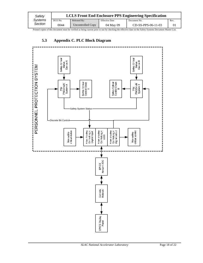
4.2.6 Block Diagram
A block diagram of the FEE PPS architecture is included in Appendix C. Safety critical devices are wired to the redundant, safety PLCs. Each of the redundant PLCs controls one chain of the redundant, safety-critical control. Network communication between the safety PLCs and the general purpose PLC is over a DeviceNet network dedicated to PPS use.
4.3 Programmable Logic Controllers (PLCs)
4.3.1 PLC Selection
a. Safety Critical Status and Control
The PLC selected for critical interlock devices is the Pilz PNOZ m1p. The Programming and Debugging Tool is the Pilz PNOZmulti Configurator. The PNOZ m1p is a modular programmable safety system for use in safety-critical applications up to Category 4 according to EN-954 and Safety Integrity Level 3 (SIL 3) according to IEC 61508.
b. General Status and Control
The PLC selected for general purpose use is the Allen Bradley ControlLogix system. The Programming and Debugging Tool for ControlLogix is RSLogix 5000. This Allen Bradley system was chosen for the body of experience available at SLAC to integrate the safety system into the control system in a safe and reliable manner.
LCLS Front End Enclosure PPS Engineering Specification DCO No. Released By: Effective Date Document No. Rev.
Safety Systems Section 0044 Uncontrolled Copy 04 May 09 CD-SS-PPS-06-11-03 01
Printed copies of this document must be verified as being current prior to use by checking the effective date on the Safety Systems Document Master List.
SLAC National Accelerator Laboratory Page 9 of 22
4.3.2 Modularity
Both the Pilz PNOZ and Allen Bradley ControlLogix systems are modular. The ControlLogix system is a standard industrial PLC with modules that are electronically keyed to prevent incorrectly configuring the system. The Pilz system contains redundant CPUs and I/O in an integrated package. Distributed I/O modules may be added when the 20 inputs and 2 outputs (integrated with the controller) are insufficient.
4.3.3 Self Checking
The ControlLogix architecture provides the user with methods of detecting and reacting to faults in the system. The Pilz architecture provides embedded fault detection routines. When a fault is detected in either system the faulted PLC will set all outputs to a safe state and trigger an alarm hardwired to the MCC Primary Annunciator alarm panel.
The Pilz PLC has four pulsed output voltages that are used as Monitored Interlock Voltages. Inputs look for these diagnostic pulses. The controller fails safe if the pulse is not detected or is not in the correct time frame. The monitored interlock voltages are sensed by the inputs to verify that no cross wiring or shorting has occurred. Chain B monitored interlock voltages are wired (A+2) modulo 4 such that Chain A and Chain B software is incompatible.
4.3.4 Testability
To the maximum extent possible, press-to-test switches and status indicators are incorporated into the design to permit efficient testing and certification of the system.
4.3.5 Redundancy
The FEE PPS is interlocked by redundant, safety PLCs. Each safety PLC receives status from each safety critical device. After interlock conditions are determined to be met, each safety PLC issues one of the two permissives required to actuate a safety critical device. A block diagram is provided in Appendix C.
Each safety PLC runs a version of software developed independently by two different programmers.
4.3.6 Security
The PPS logic package is secured in a locked PPS rack. The ControlLogix PLC has a TCP/IP communications module for system status which is connected to the controls system network through an

LCLS Front End Enclosure PPS Engineering Specification DCO No. Released By: Effective Date Document No. Rev.
Safety Systems Section 0044 Uncontrolled Copy 04 May 09 CD-SS-PPS-06-11-03 01
Printed copies of this document must be verified as being current prior to use by checking the effective date on the Safety Systems Document Master List.
SLAC National Accelerator Laboratory Page 10 of 22
EPICS IOC. The IOC provides status to the control system from the PLC.
Communication from the control system is sent to the PLC through the IOC. The PLC side of the communications is a VPN (Virtual Private Network). A hardwired permissive signal is sent to the PLC together with the control system communication to authenticate all messages sent to the PLC.
The Pilz system sends data to the ControlLogix PLC over a dedicated PPS DeviceNet network. This communication is read-only, therefore the only way to write information to the Pilz PLC is through the serial port. The Pilz PLC program is contained on a Smart Card chip. When the Smart Card is finalized the program can not be modified. The outputs transition to the de-energized state if the Smart Card is removed from the Pilz PLC.
4.3.7 Configuration Control
Configuration of the PPS is tightly controlled in accordance with the SLAC Guidelines for Operations. Requests for system modification must be submitted to the PPS Group Leader. The PPS Group Leader then assigns an engineer to the task. Prior to modification, the PPS group submits relevant documentation to the ADSO (Accelerator Department Safety Officer). The ADSO oversees the review process and grants permission to proceed with the modification. Modification of the PPS continues in accordance with the SLAC Guidelines for Operations, Section 14, Configuration Control of Radiation Safety Systems.
After the system has been modified it undergoes a rigorous Certification Test to ensure that code complies with its specified requirements.
4.3.8 Revision Control
Revision control is specified in the PPS Group Software Configuration Management Procedure (18-17-07).
4.3.9 Regular Certification
The FEE PPS will be certified regularly in accordance with the SLAC Guidelines for Operations, Section 27, Testing of Personnel Protection Systems. Verification of the software version is a prerequisite to performing the certification procedure.
4.3.10 Boolean Expressions
A set of Boolean expressions are provided in Appendix B.
LCLS Front End Enclosure PPS Engineering Specification DCO No. Released By: Effective Date Document No. Rev.
Safety Systems Section 0044 Uncontrolled Copy 04 May 09 CD-SS-PPS-06-11-03 01
Printed copies of this document must be verified as being current prior to use by checking the effective date on the Safety Systems Document Master List.
SLAC National Accelerator Laboratory Page 11 of 22
5.0 Appendix
5.1 Appendix A. FEE PPS Component List
5.2 Appendix B. FEE Boolean Expressions
5.3 Appendix C. PLC Block Diagram
5.4 Appendix D. Failure Analysis of Allen-Bradley PLC Functions
LCLS Front End Enclosure PPS Engineering Specification DCO No. Released By: Effective Date Document No. Rev.
Safety Systems Section 0044 Uncontrolled Copy 04 May 09 CD-SS-PPS-06-11-03 01
Printed copies of this document must be verified as being current prior to use by checking the effective date on the Safety Systems Document Master List.
SLAC National Accelerator Laboratory Page 12 of 22
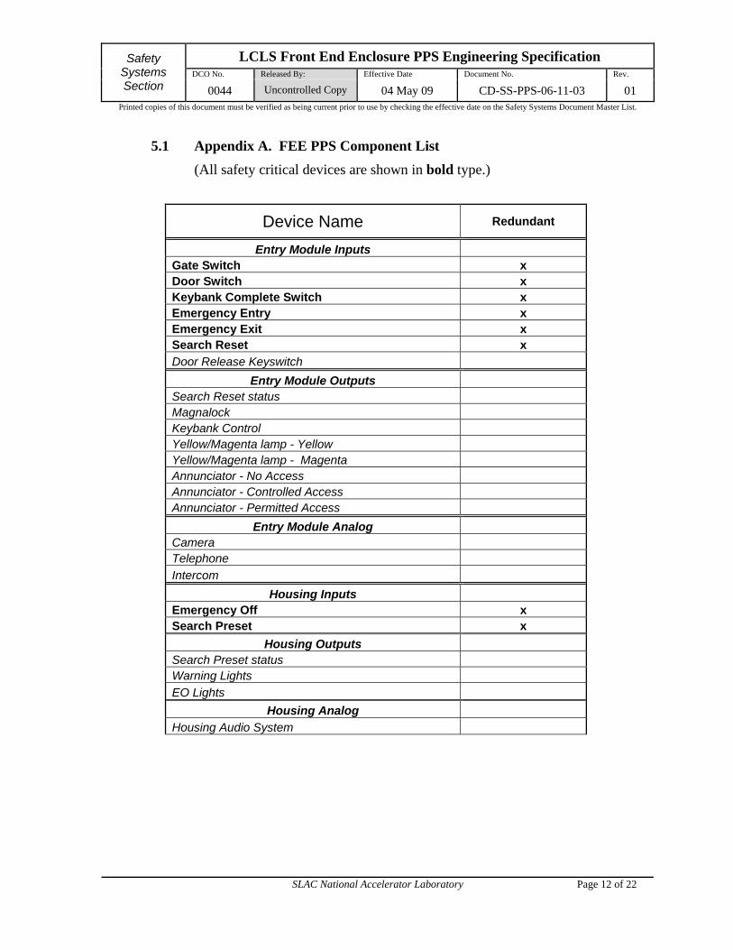
5.1 Appendix A. FEE PPS Component List
(All safety critical devices are shown in bold type.)
Device Name Redundant
Entry Module Inputs Gate Switch x Door Switch x Keybank Complete Switch x Emergency Entry x Emergency Exit x Search Reset x
Door Release Keyswitch
Entry Module Outputs Search Reset status Magnalock Keybank Control Yellow/Magenta lamp - Yellow Yellow/Magenta lamp - Magenta Annunciator - No Access Annunciator - Controlled Access Annunciator - Permitted Access
Entry Module Analog Camera Telephone
Intercom
Housing Inputs Emergency Off x Search Preset x
Housing Outputs Search Preset status Warning Lights
EO Lights
Housing Analog
Housing Audio System
LCLS Front End Enclosure PPS Engineering Specification DCO No. Released By: Effective Date Document No. Rev.
Safety Systems Section 0044 Uncontrolled Copy 04 May 09 CD-SS-PPS-06-11-03 01
Printed copies of this document must be verified as being current prior to use by checking the effective date on the Safety Systems Document Master List.
SLAC National Accelerator Laboratory Page 13 of 22
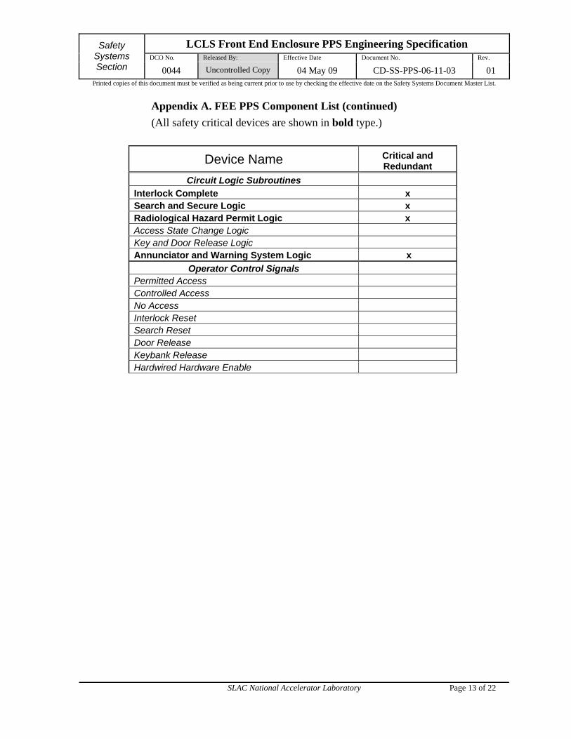
Appendix A. FEE PPS Component List (continued)
(All safety critical devices are shown in bold type.)
Device Name Critical and Redundant
Circuit Logic Subroutines
Interlock Complete x Search and Secure Logic x Radiological Hazard Permit Logic x Access State Change Logic Key and Door Release Logic Annunciator and Warning System Logic x
Operator Control Signals Permitted Access Controlled Access No Access Interlock Reset Search Reset Door Release Keybank Release Hardwired Hardware Enable

LCLS Front End Enclosure PPS Engineering Specification DCO No. Released By: Effective Date Document No. Rev.
Safety Systems Section 0044 Uncontrolled Copy 04 May 09 CD-SS-PPS-06-11-03 01
Printed copies of this document must be verified as being current prior to use by checking the effective date on the Safety Systems Document Master List.
SLAC National Accelerator Laboratory Page 14 of 22
5.2 Appendix B. FEE Boolean Expressions
Safety Critical Interlock Logic The safety critical logic is controlled through redundant Pilz safety controllers. The application software is developed by two PPS engineers working independently using the same specification. The Chain A and Chain B logic are independent of each other with the exception of the stopper permissive which is cross interlocked for safety and reliability. The cross interlock may be bypassed through the use of an external keyswitch to test the logic. In this special test mode stopper permits are displayed on the hardware panel but stoppers are disabled.
EO latch
EO_SUM = EO_01 * EO_02 * EO_03 * ... * EO_XX
EO_LTCH = (EO_SUM * CA * MCC_RST) + (EO_SUM * EO_LTCH)
EE latch
EE_LTCH = (EE * CA * MCC_RST) + (EE * EE_LTCH)
Door latch
DOOR_SUM = DOOR_L * DOOR_R
DOOR_LTCH = (DOOR_SUM * CA * MCC_RST) + (DOOR_SUM * DOOR_LTCH)
Gate latch
GATE_SUM = GATE_L * GATE_R
GATE_LTCH = (GATE_SUM * CA * MCC_RST) + (GATE_SUM * GATE_LTCH)
Keybank latch
KB_LTCH = (KB * CA * MCC_RST) + (KB * EE_LTCH)
Interlocks Complete
ILCK_CMPLT = EO_LTCH * EE_LTCH * DOOR_LTCH * GATE_LTCH * KB_LTCH
LCLS Front End Enclosure PPS Engineering Specification DCO No. Released By: Effective Date Document No. Rev.
Safety Systems Section 0044 Uncontrolled Copy 04 May 09 CD-SS-PPS-06-11-03 01
Printed copies of this document must be verified as being current prior to use by checking the effective date on the Safety Systems Document Master List.
SLAC National Accelerator Laboratory Page 15 of 22
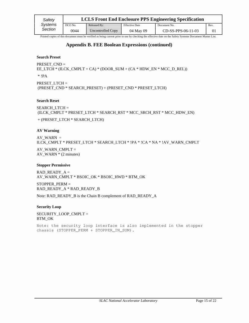
Appendix B. FEE Boolean Expressions (continued)
Search Preset
PRESET_CND = EE_LTCH * (ILCK_CMPLT + CA) * (DOOR_SUM + (CA * HDW_EN * MCC_D_REL))
* !PA
PRESET_LTCH = (PRESET_CND * SEARCH_PRESET) + (PRESET_CND * PRESET_LTCH)
Search Reset
SEARCH_LTCH = (ILCK_CMPLT * PRESET_LTCH * SEARCH_RST * MCC_SRCH_RST * MCC_HDW_EN)
+ (PRESET_LTCH * SEARCH_LTCH)
AV Warning
AV_WARN = ILCK_CMPLT * PRESET_LTCH * SEARCH_LTCH * !PA * !CA * NA * !AV_WARN_CMPLT
AV_WARN_CMPLT = AV_WARN * (2 minutes)
Stopper Permissive
RAD_READY_A = AV_WARN_CMPLT * BSOIC_OK * BSOIC_HWD * BTM_OK
STOPPER_PERM = RAD_READY_A * RAD_READY_B
Note: RAD_READY_B is the Chain B complement of RAD_READY_A
Security Loop
SECURITY_LOOP_CMPLT = BTM_OK
Note: the security loop interface is also implemented in the stopper chassis (STOPPER_PERM + STOPPER_IN_SUM).

LCLS Front End Enclosure PPS Engineering Specification DCO No. Released By: Effective Date Document No. Rev.
Safety Systems Section 0044 Uncontrolled Copy 04 May 09 CD-SS-PPS-06-11-03 01
Printed copies of this document must be verified as being current prior to use by checking the effective date on the Safety Systems Document Master List.
SLAC National Accelerator Laboratory Page 16 of 22
Appendix B. FEE Boolean Expressions (continued)
Access Control Logic The Access Control logic is preformed by an Allen-Bradley PLC. The Allen-Bradley PLC provides a distinct separation of process control functions from safety interlock functions. In addition the Allen-Bradley PLC provides an interface to EPICS to display the status of the safety critical systems and provides summary status to field devices such as the search preset and search reset devices.
Signals from the Safety Critical Interlock Logic are A*B summed. The summary is not explicitly shown to simplify the expressions.
Door release
!MAGNALOCK = PA + !EE_LTCH + (CA * DOOR_REL * MCC_DOOR_REL * MCC_HDW_EN)
KB release
KB_REL = CA * MCC_KB_REL * MCC_HDW_EN
Yellow/Magenta
YELLOW = STOPPER_IN_SUM * (PA + CA)
MAGENTA = !YELLOW * !FLASH_MAGENTA
FLASH_MAGENTA = !STOPPER_IN_SUM
EO Indicator Lights
EO_FLASH = STOPPER_PERM
EO_STEADY = !EO_FLASH
LCLS Front End Enclosure PPS Engineering Specification DCO No. Released By: Effective Date Document No. Rev.
Safety Systems Section 0044 Uncontrolled Copy 04 May 09 CD-SS-PPS-06-11-03 01
Printed copies of this document must be verified as being current prior to use by checking the effective date on the Safety Systems Document Master List.
SLAC National Accelerator Laboratory Page 17 of 22
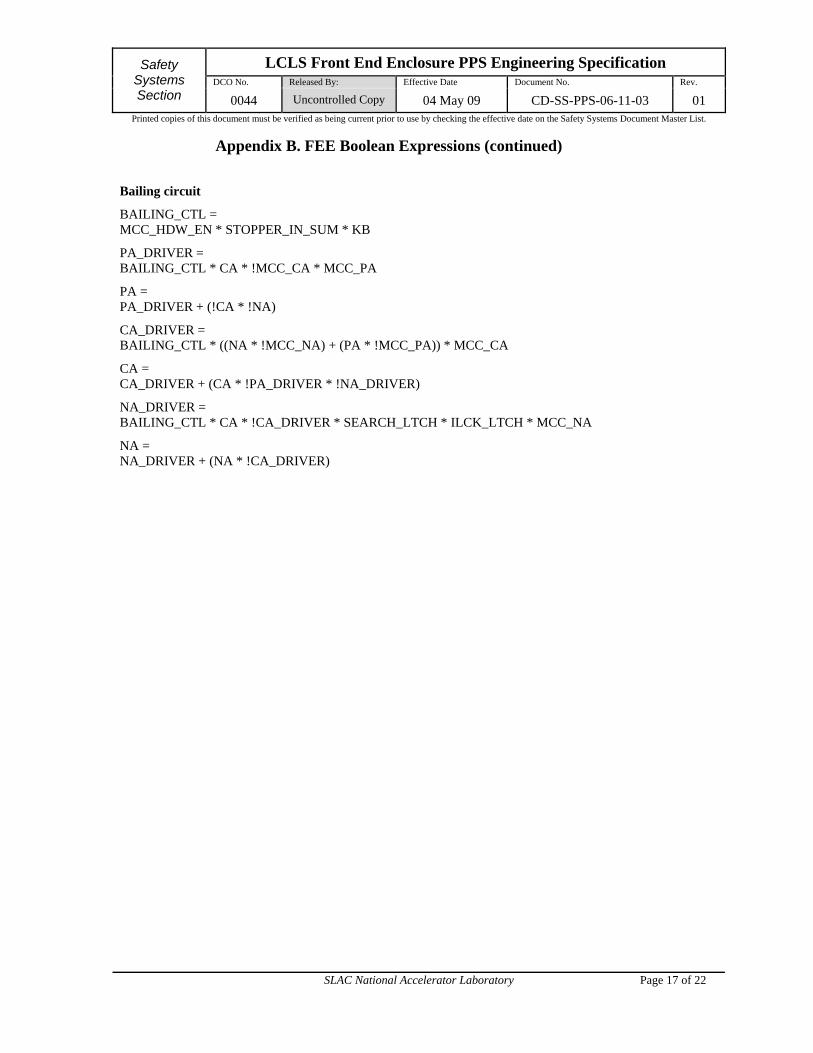
Appendix B. FEE Boolean Expressions (continued)
Bailing circuit
BAILING_CTL = MCC_HDW_EN * STOPPER_IN_SUM * KB
PA_DRIVER = BAILING_CTL * CA * !MCC_CA * MCC_PA
PA = PA_DRIVER + (!CA * !NA)
CA_DRIVER = BAILING_CTL * ((NA * !MCC_NA) + (PA * !MCC_PA)) * MCC_CA
CA = CA_DRIVER + (CA * !PA_DRIVER * !NA_DRIVER)
NA_DRIVER = BAILING_CTL * CA * !CA_DRIVER * SEARCH_LTCH * ILCK_LTCH * MCC_NA
NA = NA_DRIVER + (NA * !CA_DRIVER)
LCLS Front End Enclosure PPS Engineering Specification DCO No. Released By: Effective Date Document No. Rev.
Safety Systems Section 0044 Uncontrolled Copy 04 May 09 CD-SS-PPS-06-11-03 01
Printed copies of this document must be verified as being current prior to use by checking the effective date on the Safety Systems Document Master List.
SLAC National Accelerator Laboratory Page 18 of 22
5.3 Appendix C. PLC Block Diagram
Discrete Bit Control
Safety System Status
LCLS Front End Enclosure PPS Engineering Specification DCO No. Released By: Effective Date Document No. Rev.
Safety Systems Section 0044 Uncontrolled Copy 04 May 09 CD-SS-PPS-06-11-03 01
Printed copies of this document must be verified as being current prior to use by checking the effective date on the Safety Systems Document Master List.
SLAC National Accelerator Laboratory Page 19 of 22
5.4 Appendix D. Failure Analysis of Allen-Bradley PLC Functions
This appendix provides an exhaustive failure analysis of all Allen-Bradley PLC functions. All functions performed by the Allen-Bradley are considered non safety-critical and this analysis is intended to affirm that assertion. All safety-critical functions are implemented redundantly with the two Pilz PNOZmulti PLCs.
A function is deemed non safety-critical if its failure does not compromise full redundant protection of personnel from prompt radiation. Overall safety is not compromised by performing these functions with non-redundant methods. Most, if not all, of these functions pose serious technical challenges to perform redundantly.
Only the worst-case for several similar cases are analyzed below. For example, setting No Access without keybank complete is included below; setting Controlled Access or Permitted Access without the keybank complete is not. Setting No Access with a door open is included below, setting Controlled Access or Permitted Access with a door open is not.

LCLS Front End Enclosure PPS Engineering Specification DCO No. Released By: Effective Date Document No. Rev.
Safety Systems Section 0044 Uncontrolled Copy 04 May 09 CD-SS-PPS-06-11-03 01
Printed copies of this document must be verified as being current prior to use by checking the effective date on the Safety Systems Document Master List.
SLAC National Accelerator Laboratory Page 20 of 22
Table 1: Safety-Critical Hazard Mitigation of Non Safety-Critical Function Failures
Allen-Bradley Subroutine
Inappropriate Allen-Bradley Function
Redundant Safety-Critical Hazard Mitigation by Pilz PNOZmulti PLCs
Access Control Keybank key release in No Access
Each safety-critical PLC directly and independently senses ‘keybank complete’ status. Loss of this status in No Access will result in loss of ‘search set’ status. In addition, the PPS door must actually be opened in order to expose personnel to a hazardous condition. This is equivalent to an emergency entry.
Access Control Door release in No Access Each safety-critical PLC directly and independently senses ‘door closed’ status. Loss of door-closed status in No Access will result in loss of ‘search set’ status. This is equivalent to an emergency entry.
Access Control Door release in Controlled Access without MCC Hardwire Enable
Each safety-critical PLC directly and independently senses ‘door closed’ status and the MCC Hardwire Enable. Loss of door-closed status in Controlled Access without simultaneously sensing the MCC Hardwire Enable will result in loss of ‘search set’ status. This is equivalent to an emergency entry.
Bailing Control No Access is set to Controlled Access or Permitted Access with Stoppers ‘out’ and/or RF ‘on’
Each safety-critical PLC
has its own search ‘set’ status,
directly and independently monitors stopper position,
transmits a stopper permit.
Therefore, this condition will result in a loss of permits to all radiation hazards. This is equivalent to an emergency entry.
Bailing Control No Access is set without Search Reset set
Each safety-critical PLC has its own search ‘set’ status; without this search status, permits will never be sent to equipment. This is equivalent to the post emergency entry state of the PPS.
Bailing Control No Access is set without Keybank ‘complete’ status
Each safety-critical PLC directly and independently senses ‘keybank complete’ status. Bailing to No Access without ‘keybank complete’ will immediately result in loss of ‘search set’ status. This is equivalent to an emergency entry.
LCLS Front End Enclosure PPS Engineering Specification DCO No. Released By: Effective Date Document No. Rev.
Safety Systems Section 0044 Uncontrolled Copy 04 May 09 CD-SS-PPS-06-11-03 01
Printed copies of this document must be verified as being current prior to use by checking the effective date on the Safety Systems Document Master List.
SLAC National Accelerator Laboratory Page 21 of 22
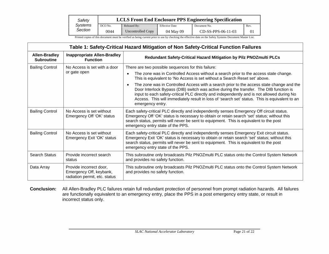
Table 1: Safety-Critical Hazard Mitigation of Non Safety-Critical Function Failures
Allen-Bradley Subroutine
Inappropriate Allen-Bradley Function
Redundant Safety-Critical Hazard Mitigation by Pilz PNOZmulti PLCs
Bailing Control No Access is set with a door or gate open
There are two possible sequences for this failure:
The zone was in Controlled Access without a search prior to the access state change. This is equivalent to ‘No Access is set without a Search Reset set’ above.
The zone was in Controlled Access with a search prior to the access state change and the Door Interlock Bypass (DIB) switch was active during the transfer. The DIB function is input to each safety-critical PLC directly and independently and is not allowed during No Access. This will immediately result in loss of ‘search set’ status. This is equivalent to an emergency entry.
Bailing Control No Access is set without Emergency Off ‘OK’ status
Each safety-critical PLC directly and independently senses Emergency Off circuit status. Emergency Off ‘OK’ status is necessary to obtain or retain search ‘set’ status; without this search status, permits will never be sent to equipment. This is equivalent to the post emergency entry state of the PPS.
Bailing Control No Access is set without Emergency Exit ‘OK’ status
Each safety-critical PLC directly and independently senses Emergency Exit circuit status. Emergency Exit ‘OK’ status is necessary to obtain or retain search ‘set’ status; without this search status, permits will never be sent to equipment. This is equivalent to the post emergency entry state of the PPS.
Search Status Provide incorrect search status
This subroutine only broadcasts Pilz PNOZmulti PLC status onto the Control System Network and provides no safety function.
Data Array Provide incorrect door, Emergency Off, keybank, radiation permit, etc. status
This subroutine only broadcasts Pilz PNOZmulti PLC status onto the Control System Network and provides no safety function.
Conclusion: All Allen-Bradley PLC failures retain full redundant protection of personnel from prompt radiation hazards. All failures
are functionally equivalent to an emergency entry, place the PPS in a post emergency entry state, or result in incorrect status only.
LCLS Front End Enclosure PPS Engineering Specification DCO No. Released By: Effective Date Document No. Rev.
Safety Systems Section 0044 Uncontrolled Copy 04 May 09 CD-SS-PPS-06-11-03 01
Printed copies of this document must be verified as being current prior to use by checking the effective date on the Safety Systems Document Master List.
SLAC National Accelerator Laboratory Page 22 of 22
6.0 Revision History
Rev No. Effective Date DCO No.
01 04 May 09 0044