lc sensor rotation detection with msp430 extended · pdf filelc sensor rotation detection with...
TRANSCRIPT
1SLAA639–July 2014Submit Documentation Feedback
Copyright © 2014, Texas Instruments Incorporated
LC Sensor Rotation Detection With MSP430™ Extended Scan Interface(ESI)
Application ReportSLAA639–July 2014
LC Sensor Rotation Detection With MSP430™ ExtendedScan Interface (ESI)
ThomasKot
ABSTRACTThis application report describes the implementation of a flow meter using the Texas InstrumentsMSP430FR6989 microcontroller with the Extended Scan Interface (ESI) module. This module can providea contactless sensing approach to detecting a rotating disc. The number of rotations of the disc indicatesthe volume flow of gas or water and can be used to calculate the fee for the user. This application is goodfor gas or water meters. This application also includes the necessary information with regard to softwareand hardware procedures for the Water Meter Reference Design for two LC Sensors, Using ExtendedScan Interface (ESI) (TIDM-LC-WATERMTR).
The software described in this app note can be downloaded from http://www.ti.com/lit/zip/tidc583.
Topic ........................................................................................................................... Page
1 Introduction ........................................................................................................ 22 Working Principle of LC Sensors ........................................................................... 23 Hardware Implementation With ESI ........................................................................ 64 Software Implementation ...................................................................................... 85 Runtime Calibration With AFE2 ............................................................................ 176 Demo and Operation........................................................................................... 197 References ........................................................................................................ 268 Schematics........................................................................................................ 26
Introduction www.ti.com
2 SLAA639–July 2014Submit Documentation Feedback
Copyright © 2014, Texas Instruments Incorporated
LC Sensor Rotation Detection With MSP430™ Extended Scan Interface(ESI)
TrademarksMSP430 is a trademark of Texas Instruments.All other trademarks are the property of their respective owners.
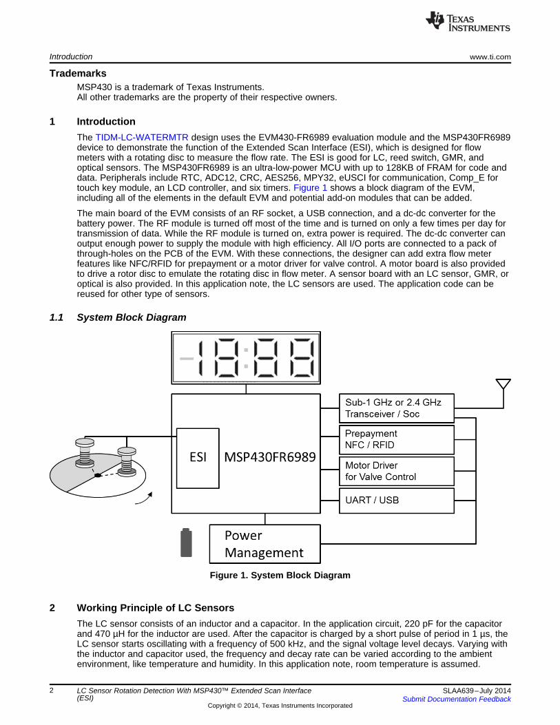
1 IntroductionThe TIDM-LC-WATERMTR design uses the EVM430-FR6989 evaluation module and the MSP430FR6989device to demonstrate the function of the Extended Scan Interface (ESI), which is designed for flowmeters with a rotating disc to measure the flow rate. The ESI is good for LC, reed switch, GMR, andoptical sensors. The MSP430FR6989 is an ultra-low-power MCU with up to 128KB of FRAM for code anddata. Peripherals include RTC, ADC12, CRC, AES256, MPY32, eUSCI for communication, Comp_E fortouch key module, an LCD controller, and six timers. Figure 1 shows a block diagram of the EVM,including all of the elements in the default EVM and potential add-on modules that can be added.
The main board of the EVM consists of an RF socket, a USB connection, and a dc-dc converter for thebattery power. The RF module is turned off most of the time and is turned on only a few times per day fortransmission of data. While the RF module is turned on, extra power is required. The dc-dc converter canoutput enough power to supply the module with high efficiency. All I/O ports are connected to a pack ofthrough-holes on the PCB of the EVM. With these connections, the designer can add extra flow meterfeatures like NFC/RFID for prepayment or a motor driver for valve control. A motor board is also providedto drive a rotor disc to emulate the rotating disc in flow meter. A sensor board with an LC sensor, GMR, oroptical is also provided. In this application note, the LC sensors are used. The application code can bereused for other type of sensors.
1.1 System Block Diagram
Figure 1. System Block Diagram
2 Working Principle of LC SensorsThe LC sensor consists of an inductor and a capacitor. In the application circuit, 220 pF for the capacitorand 470 µH for the inductor are used. After the capacitor is charged by a short pulse of period in 1 µs, theLC sensor starts oscillating with a frequency of 500 kHz, and the signal voltage level decays. Varying withthe inductor and capacitor used, the frequency and decay rate can be varied according to the ambientenvironment, like temperature and humidity. In this application note, room temperature is assumed.

www.ti.com Working Principle of LC Sensors
3SLAA639–July 2014Submit Documentation Feedback
Copyright © 2014, Texas Instruments Incorporated
LC Sensor Rotation Detection With MSP430™ Extended Scan Interface(ESI)
When there is a metal approaching the oscillating LC, the signal decays faster due to the energyabsorption by eddy current of the metal part. As shown in Figure 2, by using this characteristic, the LCsensor is used to identify metal (signal in red) or nonmetal part (signal in blue). A disc that is half coveredby metal and half by nonmetal can be constructed as a moving component to detect the flow rate. Therotation speed of the disc can then be detected by the LC sensor.
Figure 2. Oscillation Signal of Detection of Metal And Nonmetal Portions of the Rotor Disc
When overlapping these two oscillating signals of metal and nonmetal, the signal level difference of themis not constant. It starts from a small level to a largest difference in somewhere in the middle part of thesignals and then decreasing to zero. For a maximum detection distance, only the portion of signals withmaximum difference in signal level is measured (see Figure 3). This needs a timer to form a time delaybefore comparing these two signals.
Figure 3. Maximum Difference Along the Decaying LC Signal
To detect the metal and nonmetal signals, the EVM needs a reference signal with a voltage level be set inbetween the "red" and "blue" of the LC signals. In the ESI module, a DAC with 12-bit resolution isprovided for this function. For analog hysteresis, two voltage references are provided from the DACmodule of the ESI (see Figure 4). A comparator is then used to identify the metal and nonmetal parts ofthe disc.
Working Principle of LC Sensors www.ti.com
4 SLAA639–July 2014Submit Documentation Feedback
Copyright © 2014, Texas Instruments Incorporated
LC Sensor Rotation Detection With MSP430™ Extended Scan Interface(ESI)
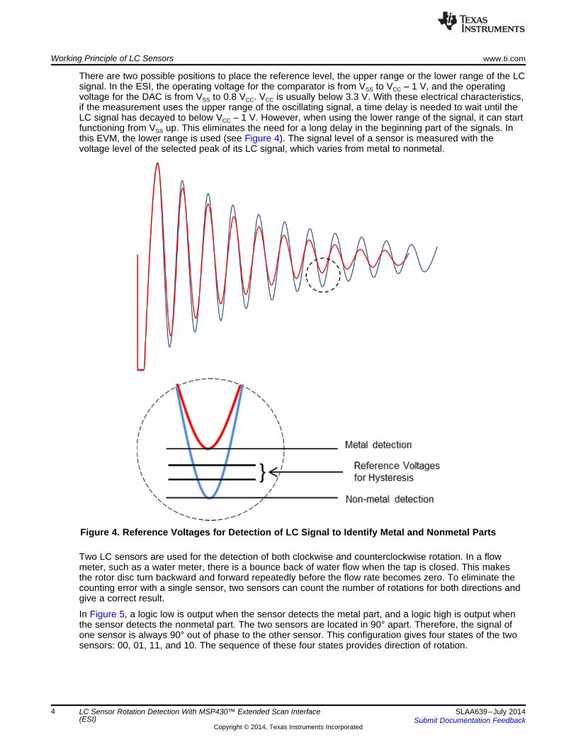
There are two possible positions to place the reference level, the upper range or the lower range of the LCsignal. In the ESI, the operating voltage for the comparator is from VSS to VCC – 1 V, and the operatingvoltage for the DAC is from VSS to 0.8 VCC. VCC is usually below 3.3 V. With these electrical characteristics,if the measurement uses the upper range of the oscillating signal, a time delay is needed to wait until theLC signal has decayed to below VCC – 1 V. However, when using the lower range of the signal, it can startfunctioning from VSS up. This eliminates the need for a long delay in the beginning part of the signals. Inthis EVM, the lower range is used (see Figure 4). The signal level of a sensor is measured with thevoltage level of the selected peak of its LC signal, which varies from metal to nonmetal.
Figure 4. Reference Voltages for Detection of LC Signal to Identify Metal and Nonmetal Parts
Two LC sensors are used for the detection of both clockwise and counterclockwise rotation. In a flowmeter, such as a water meter, there is a bounce back of water flow when the tap is closed. This makesthe rotor disc turn backward and forward repeatedly before the flow rate becomes zero. To eliminate thecounting error with a single sensor, two sensors can count the number of rotations for both directions andgive a correct result.
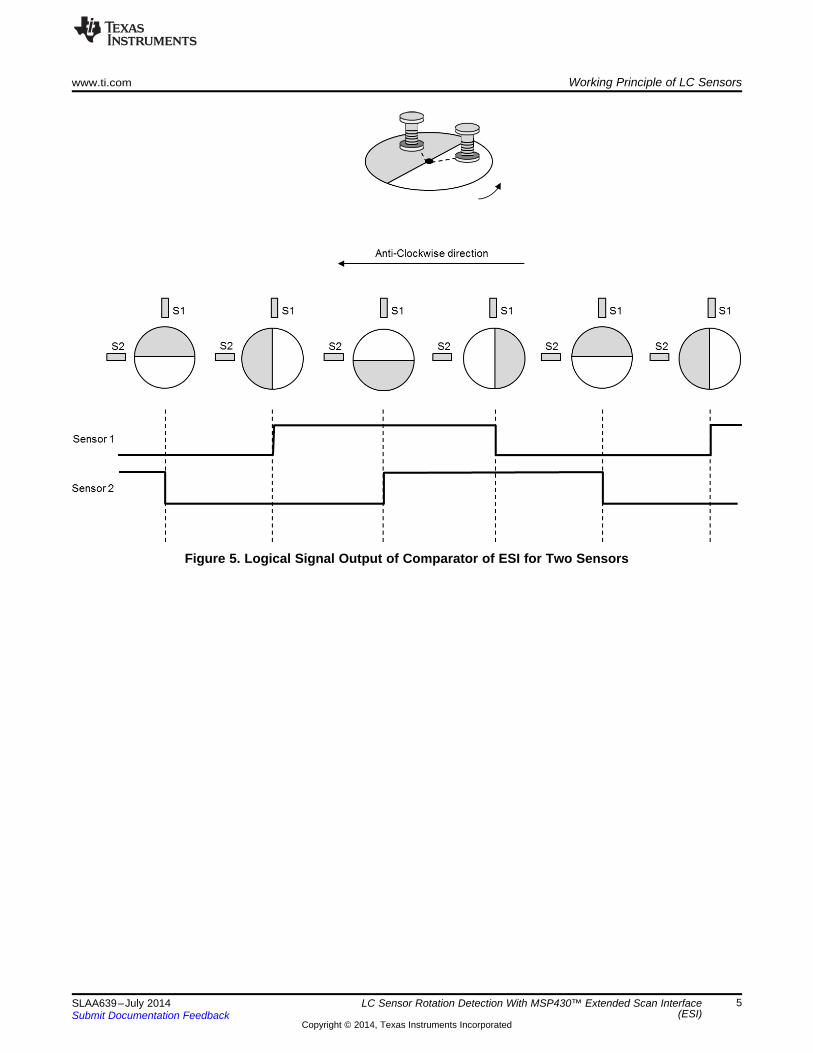
In Figure 5, a logic low is output when the sensor detects the metal part, and a logic high is output whenthe sensor detects the nonmetal part. The two sensors are located in 90° apart. Therefore, the signal ofone sensor is always 90° out of phase to the other sensor. This configuration gives four states of the twosensors: 00, 01, 11, and 10. The sequence of these four states provides direction of rotation.
www.ti.com Working Principle of LC Sensors
5SLAA639–July 2014Submit Documentation Feedback
Copyright © 2014, Texas Instruments Incorporated
LC Sensor Rotation Detection With MSP430™ Extended Scan Interface(ESI)
Figure 5. Logical Signal Output of Comparator of ESI for Two Sensors

Hardware Implementation With ESI www.ti.com
6 SLAA639–July 2014Submit Documentation Feedback
Copyright © 2014, Texas Instruments Incorporated
LC Sensor Rotation Detection With MSP430™ Extended Scan Interface(ESI)
3 Hardware Implementation With ESIFigure 6 shows the block diagram of the ESI. There are three clock sources, ACLK of 32768 Hz, a built-ininternal oscillator (ESIOSC) of ESI for a high-frequency clock source, and the SMCLK using the DCO. Inthe EVM, ACLK and ESIOSC are used.
Figure 6. Block Diagram of the ESI
There are two analog front ends, AFE1 and AFE2. AFE1 provides VCC/2 as the ac ground of the LC signaland an excitation circuit to provide a short pulse in the range of microseconds for the excitation of LCoscillation. Up to four sensors can be connected to the four channels of the ESI. For each channel, thesensors are excited one by one.
The input signal of a sensor is connected to the positive input of a comparator. The negative input isconnected to the 12-bit DAC. Two registers of the DAC for each channel provide two reference levels toimplement hysteresis that avoids signal oscillation in the output of the comparator.
The 32 registers of the Timing State Machine (TSM) provide the timing sequence to control the on and offof the internal parts of the ESI module. The output of the comparator for each channel is stored in aregister of the Preprocessing Unit (ESIPPU). After the completion of one cycle of measurement for allsensors (using two sensors in this EVM), an ESISTOP signal is generated to trigger the operation ofProcessing State Machine (PSM) to analysis the rotation direction and count the rotation number. Themaximum number of processing channels is three out of four selectable channels. The channels areselected in ESIPPU, and their outputs are processed by PSM.
The AFE2 has DAC registers and a comparator. The inputs to the AFE2 share the same channelsselection circuit of AFE1. With this configuration, the AFE2 measures the same signal that is beingmeasured by AFE1. The outputs of AFE2 are stored in the ESIPPU. This design enables AFE2 to be themirror of AFE1 and to perform a runtime recalibration of AFE1 without interfering with the normal operationof AFE1.

www.ti.com Hardware Implementation With ESI
7SLAA639–July 2014Submit Documentation Feedback
Copyright © 2014, Texas Instruments Incorporated
LC Sensor Rotation Detection With MSP430™ Extended Scan Interface(ESI)
3.1 Rotor Plate and Detection DistanceThe rotor plate or disc is used to detect the flow rate. This is a round disc that is half covered with metaland half covered with nonmetal. For a reasonable detection distance, the metal area cannot be too small,because a larger metal area has more absorption rate of the magnetic energy from the inductor of the LCsensor. The detection distance also relies on the concentration of the magnetic field from the inductor.When the disc is rotating, the LC sensor gives a large signal in the nonmetal part and a small signal in themetal part. The signal level is a continuous change from high to low and low to high. When the sensor islocated in between the metal and nonmetal area, the signal is also between the maximum and minimumlevels (see Figure 7).
Figure 7. Signal Levels From Two Sensors
Each sensor signal has a 90° phase angle from the other. When the rotor disc rotates in clockwisedirection, sensor 2 detects a high signal level when it is in the middle of nonmetal portion, and the signallevel gradually decreases to a low level when detecting the middle of the metal portion.
There are two voltage references from DAC. When signal is in high level, the lower voltage reference isused, interpreting with logic high. As the rotor disc is rotating, the signal level changes from high to low,then low to high, and repeats continuously. A logic low results when the signal is lower than the lowerreference. At the same time, the voltage reference is switched to the upper voltage reference to formanalog hysteresis. It has logic high again only when the signal level is higher than the upper voltagereference. Similarly at this time, the voltage reference is switched to lower voltage reference.
Four states (11, 01, 00, and 10) are obtained, and each state occupies the same period of time. If thesensors are not placed 90° apart, some states have a shorter time period. This implies that a highersampling rate is required to detect them, which increases power consumption.
The maximum detection distance is obtained with a large area of metal portion and an inductor designedto concentrate the magnetic field on to the metal area. Sensors have to output 90° phase angle. For amaximized solution, the rotor disc must be half covered with metal and half with nonmetal.
Software Implementation www.ti.com
8 SLAA639–July 2014Submit Documentation Feedback
Copyright © 2014, Texas Instruments Incorporated
LC Sensor Rotation Detection With MSP430™ Extended Scan Interface(ESI)
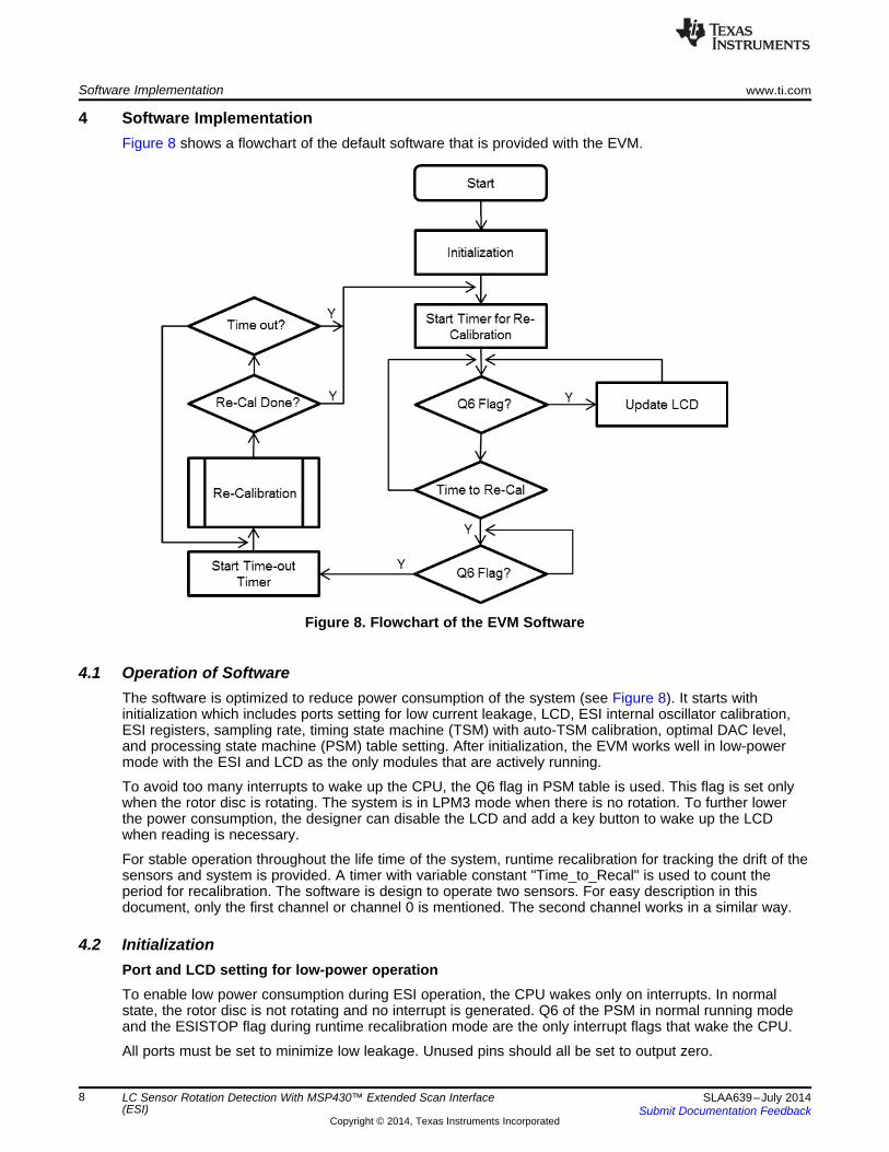
4 Software ImplementationFigure 8 shows a flowchart of the default software that is provided with the EVM.
Figure 8. Flowchart of the EVM Software
4.1 Operation of SoftwareThe software is optimized to reduce power consumption of the system (see Figure 8). It starts withinitialization which includes ports setting for low current leakage, LCD, ESI internal oscillator calibration,ESI registers, sampling rate, timing state machine (TSM) with auto-TSM calibration, optimal DAC level,and processing state machine (PSM) table setting. After initialization, the EVM works well in low-powermode with the ESI and LCD as the only modules that are actively running.
To avoid too many interrupts to wake up the CPU, the Q6 flag in PSM table is used. This flag is set onlywhen the rotor disc is rotating. The system is in LPM3 mode when there is no rotation. To further lowerthe power consumption, the designer can disable the LCD and add a key button to wake up the LCDwhen reading is necessary.
For stable operation throughout the life time of the system, runtime recalibration for tracking the drift of thesensors and system is provided. A timer with variable constant "Time_to_Recal" is used to count theperiod for recalibration. The software is design to operate two sensors. For easy description in thisdocument, only the first channel or channel 0 is mentioned. The second channel works in a similar way.
4.2 InitializationPort and LCD setting for low-power operationTo enable low power consumption during ESI operation, the CPU wakes only on interrupts. In normalstate, the rotor disc is not rotating and no interrupt is generated. Q6 of the PSM in normal running modeand the ESISTOP flag during runtime recalibration mode are the only interrupt flags that wake the CPU.
All ports must be set to minimize low leakage. Unused pins should all be set to output zero.
www.ti.com Software Implementation
9SLAA639–July 2014Submit Documentation Feedback
Copyright © 2014, Texas Instruments Incorporated
LC Sensor Rotation Detection With MSP430™ Extended Scan Interface(ESI)
Port 1.2 is used as ADC input for the key pad. This port pin is set to be input mode with the pullup resistorenabled.
For Port 9 pins that are multiplexed with ESICH0 to ESICH3, all P9SEL0 and P9SEL1 register bits mustbe set to 1 for the operation of the ESI function, even when working with two channels. At the same time,the peripheral comparator has pins multiplexed with ESI. The port disable register must be set to preventparasitic current during the transition level of the gates in the port pins. To disable the port, CECTL3 mustbe set to 1.
In the application code, the LCD is always on. To further lower the power consumption, it is suggested toturn the LCD off and to turn it only for reading.
4.3 ESI Internal Oscillator CalibrationThere are three clock sources associated with the ESI: ACLK, SMCLK, and the internal oscillator of ESI.The internal oscillator and the SMCLK are the sources of high-frequency clocks which could be used inthe TSM timing control. For low power and standalone operation of ESI, the internal oscillator is preferred.However, this clock frequency varies from device to device, so an initial calibration is required. Thecalibration code can be found in ESI_ESIOSC.c.
4.4 Sensor Sampling Rate SettingFor normal operation, the sampling rate of ESI is the frequency of triggering a LC oscillation so as todetect the position of the sensors over the rotating disc. The register used is ESITSM. The equation todetermine the rate is as follows:
Sampling Rate = Maximum Rotation Rate × Number of Samples per RotationNumber of Samples per Rotation = 2 × 360 / (Angle of smaller portion of the Disc – Angle of sensorpair)
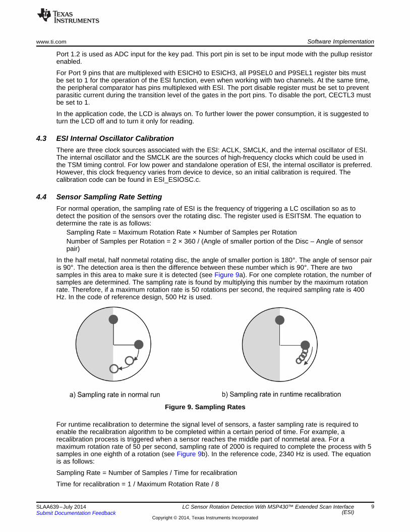
In the half metal, half nonmetal rotating disc, the angle of smaller portion is 180°. The angle of sensor pairis 90°. The detection area is then the difference between these number which is 90°. There are twosamples in this area to make sure it is detected (see Figure 9a). For one complete rotation, the number ofsamples are determined. The sampling rate is found by multiplying this number by the maximum rotationrate. Therefore, if a maximum rotation rate is 50 rotations per second, the required sampling rate is 400Hz. In the code of reference design, 500 Hz is used.
Figure 9. Sampling Rates
For runtime recalibration to determine the signal level of sensors, a faster sampling rate is required toenable the recalibration algorithm to be completed within a certain period of time. For example, arecalibration process is triggered when a sensor reaches the middle part of nonmetal area. For amaximum rotation rate of 50 per second, sampling rate of 2000 is required to complete the process with 5samples in one eighth of a rotation (see Figure 9b). In the reference code, 2340 Hz is used. The equationis as follows:
Sampling Rate = Number of Samples / Time for recalibration
Time for recalibration = 1 / Maximum Rotation Rate / 8

Software Implementation www.ti.com
10 SLAA639–July 2014Submit Documentation Feedback
Copyright © 2014, Texas Instruments Incorporated
LC Sensor Rotation Detection With MSP430™ Extended Scan Interface(ESI)
4.5 Auto-TSM CalibrationThe Timing State Machine (TSM) is to control the timing of each state and the registers used areESITSMx. Referring to the user guide, the 5 most significant bits of the register are to determine theperiod of time for the corresponding state to last for. Afterwards, the TSM jumps to the next state.Repeating this process until the ESISTOP bit is set to complete one TSM cycle. An ESISTOP flag isgenerated and the TSM is repeated after waiting for a time interval of one sampling period. (An autorepeating setting is used in this reference code. However the TSM can be set to be restarted by softwarecontrol).
The following is the initial setting of TSM registers.ESITSM0 = 0x0400; // DAC=off, CA=off, 1xACLKESITSM1 = 0x202C; // DAC=off, CA=off, 5xESICLK, excitationESITSM2 = 0x0404; // DAC=off, CA=off, 1xACLKESITSM3 = 0x0024; // DAC=off, CA=off, 1xESIFCLK, delay tunableESITSM4 = 0x0024; // DAC=off, CA=off, 1xESIFCLK, delay tunableESITSM5 = 0x0024; // DAC=off, CA=off, 1xESIFCLK, delay tunableESITSM6 = 0x0024; // DAC=off, CA=off, 1xESIFCLK, delay tunableESITSM7 = 0x0024; // DAC=off, CA=off, 1xESIFCLK, delay tunableESITSM8 = 0x0024; // DAC=off, CA=off, 1xESIFCLK, delay tunableESITSM9 = 0xF134; // DAC=on, CA=on, 31xESIFCLK,ESITSM10 = 0x5974; // DAC=on, CA=on, OUTPUT LATCHES ENABLED, 12xESICLKESITSM11 = 0x0400; // DAC=off, CA=off, 1xACLCK, internally dampedESITSM12 = 0x0400; // DAC=off, CA=off, 1xACLCK, internally dampedESITSM13 = 0x20AD; // DAC=off, CA=off, 5xESICLK, excitationESITSM14 = 0x0485; // DAC=off, CA=off, 1xACLKESITSM15 = 0x00A5; // DAC=off, CA=off, 1xESIFCLK, delay tunableESITSM16 = 0x00A5; // DAC=off, CA=off, 1xESIFCLK, delay tunableESITSM17 = 0x00A5; // DAC=off, CA=off, 1xESIFCLK, delay tunableESITSM18 = 0x00A5; // DAC=off, CA=off, 1xESIFCLK, delay tunableESITSM19 = 0x00A5; // DAC=off, CA=off, 1xESIFCLK, delay tunableESITSM20 = 0x00A5; // DAC=off, CA=off, 1xESIFCLK, delay tunableESITSM21 = 0xF1B5; // DAC=on, CA=on, 31xESIFCLKESITSM22 = 0x59F5; // DAC=on, CA=on, OUTPUT LATCHES ENABLED, 12xESICLKESITSM23 = 0x0200; // stop
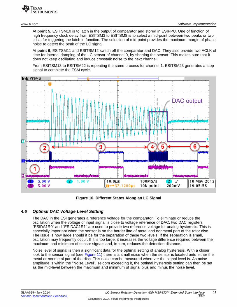
The corresponding LC signal of channel 0 is shown in Figure 10.
At point 1, the TSM starts with ESITSM0 of 0x0400 which is the beginning state of TSM cycle. This stateis to synchronize with the rising edge of ACLK. This ensures the following timing of states to be the samefor every TSM cycles.
At point 2, ESITSM1 is to make an excitation pulse for the channel 0 with timing last for 5 clock of ESIinternal oscillation. The length of the pulse must be long enough to ensure the first shot of oscillation toreach the voltage of VCC + Vdiode ( an internal protection diode of I/O). This makes every oscillationidentical.
At point 3, the LC sensor starts oscillating and its signal amplitude is getting smaller. ESITSM2 last for 1ACLK. An additional delay with high frequency clock from ESI oscillator is turned on to fine tune the delaytime and last for a period which is the sum of the time delay from ESITSM3 to ESITSM8. By usingESITSM2 to ESITSM8, an auto TSM time delay function "TSM_Auto_cal()" is constructed to tune the timedelay of the LC signal, so as to reach an optimal signal level and timing to capture a signal ( in point 5).This function is to add on one high frequency clock cycle delay every time. The captured signal is thenmeasured by a function "FindDAC()" to find its voltage level, by using the comparator and the DAC asreference voltage. With this setting, only the peak level is measured. In the reference design, an inverter isenabled to invert the output of comparator so that the crisis of LC signal is measured. If plotting the valueof the measured level into a graph, an envelope of the signal with a stair-case-shaped curve is obtained.when the signal level has reached the pre-defined level "LC_Threshold_TSM_CAL", an optimal delay isobtained at a point which is the mid-way to the next crisis.
At point 4, ESITSM9 is to turn on the comparator and DAC output. A proper delay is taken for the settlingtime.
www.ti.com Software Implementation
11SLAA639–July 2014Submit Documentation Feedback
Copyright © 2014, Texas Instruments Incorporated
LC Sensor Rotation Detection With MSP430™ Extended Scan Interface(ESI)
At point 5, ESITSM10 is to latch in the output of comparator and stored in ESIPPU. One of function ofhigh frequency clock delay from ESITSM3 to ESITSM8 is to select a mid-point between two peaks or twocrisis for triggering the latch in function. The selection of mid-point provides the maximum margin of phasenoise to detect the peak of the LC signal.
At point 6, ESITSM11 and ESITSM12 switch off the comparator and DAC. They also provide two ACLK oftime for internal damping of the LC sensor of channel 0, by shorting the sensor. This makes sure that itdoes not keep oscillating and induce crosstalk noise to the next channel.
From ESITSM13 to ESITSM22 is repeating the same process for channel 1. ESITSM23 generates a stopsignal to complete the TSM cycle.
Figure 10. Different States Along an LC Signal
4.6 Optimal DAC Voltage Level SettingThe DAC in the ESI generates a reference voltage for the comparator. To eliminate or reduce theoscillation when the voltage of input signal is close to voltage reference of DAC, two DAC registers"ESIDA1R0" and "ESIDAC1R1" are used to provide two reference voltage for analog hysteresis. This isespecially important when the sensor is on the border line of metal and nonmetal part of the rotor disc.The issue is how large should it be for the separation of these two levels. If the separation is small,oscillation may frequently occur. If it is too large, it increases the voltage difference required between themaximum and minimum of sensor signals and, in turn, reduces the detection distance.
Noise level of signal is then a significant data for the optimal setting of analog hysteresis. With a closerlook to the sensor signal (see Figure 11) there is a small noise when the sensor is located onto either themetal or nonmetal part of the disc. This noise can be measured wherever the signal level is. As noiseamplitude is within the "Noise Level", seldom exceeding it, the optimal hysteresis setting can then be setas the mid-level between the maximum and minimum of signal plus and minus the noise level.

Software Implementation www.ti.com
12 SLAA639–July 2014Submit Documentation Feedback
Copyright © 2014, Texas Instruments Incorporated
LC Sensor Rotation Detection With MSP430™ Extended Scan Interface(ESI)
ESIDAC1R1 = (Max_DAC_Ch0 + Min_DAC_Ch0)/2 + Noise_level; // "+" for INV version, "-" for nonINV versionESIDAC1R0 = (Max_DAC_Ch0 + Min_DAC_Ch0)/2 - Noise_level; // "-" for INV version, "+" for nonINV version
Figure 11. Noise Level of Signal Determines Values of Two Reference Voltages of DAC
The noise level is measured when the rotor disc is not turning. The function "Find_Noise_level()" isresponsible for this measurement, in which "FindDAC_Fast_Range()" is the algorithm to search for thesignal level. This function is to measure the variation of signal for 0.5 second with the sensors staying atthe same position over the disc. The noise level is then the difference between the maximum andminimum of the measured data.
The Max_DAC_Ch0 and Min_DAC_Ch0 of channel 0 are respectively the maximum and minimum valueof the sensor signal with the rotor disc rotating. To measure these two data, in the function "Set_DAC()",the rotor must be rotating for 1 second, making sure the metal and nonmetal part of the disc aremeasured. The channel 1 is also going through the process at the same time.
To ensure the data correctly measured, the axis of rotor disc must be mounted tightly and in aperpendicular position in reference to the senors. If it is loosely mounted, the minimum of the signal variesbecause of the varying distance between the sensors and the metal part of the disc. For nonmetal part,there is no such variation (see Figure 12a).
To increase the difference between the maximum and minimum of the signal, a metal with higher energyabsorption rate can work. From the testing, stainless steel has better absorption rate than copper, whilecopper is better than aluminum (see Figure 12b).

www.ti.com Software Implementation
13SLAA639–July 2014Submit Documentation Feedback
Copyright © 2014, Texas Instruments Incorporated
LC Sensor Rotation Detection With MSP430™ Extended Scan Interface(ESI)
Figure 12. Signal Levels
4.7 Processing State Machine (PSM)The function of PSM is to process the input from ESIPPU so as to detect the position of the sensors onthe rotor disc and then increase or decrease the rotation counters ESICNT0, ESICNT1 and ESICNT2when the rotor disc is rotating. ESICNT0 is to record the number of rotation when the rotor disc is rotatingin clockwise direction, in parallel to the direction of water flow, while the ESICNT2 is for anti-clockwiserotation. ESICNT1 is the resultant number of rotations, which records the data equivalent to ESICNT0 –ESICNT2. Interrupt flags can be set on Q6 and Q7 of the PSM vector. There are some other interruptsettings with the outputs of the counters. The family user's guide (SLAU367) explains them in more detail.In this application code, only the Q6 of PSM vector is used for the interrupt call.
There are two channels, Ch0 and Ch1. The sensors for these channels report their detection in a timelymanner according to the sampling rate. When the rotor disc is rotating, there generates four inputsnamely: 00, 01, 11 and 10 (see Figure 13). At the same time, the position of sensors over the rotor disccan be determined. Four states are used to represent the location of the sensors, namely: S0, S1, S2, andS3, with S0 indicating both sensors are on metal part; S1 for Ch0 on nonmetal and Ch1 on metal; S2 forboth sensors on nonmetal part; and S3 for Ch0 on metal and Ch1 on nonmetal part. The direction ofrotation can then be found by processing the sequence of the states.

Software Implementation www.ti.com
14 SLAA639–July 2014Submit Documentation Feedback
Copyright © 2014, Texas Instruments Incorporated
LC Sensor Rotation Detection With MSP430™ Extended Scan Interface(ESI)
Figure 13. Different States of LC Sensors When Rotor is Rotating
4.7.1 State DiagramA state diagram can then be used to clearly show the flow of the states (see Figure 14) with differentinputs and outputs. At the starting of the ESI module, the sensors are located at one of the four positionsover the rotor disc and a state is given. If the disc is not rotating, there the sensor input does not changeand the same state is kept. The output is 0. For this description, assume that the initial state is S0. Thenonrotating disc makes the sensors have 00 as input to the PSM. The state is be kept in S0 and theoutput is 0.
When the rotor is rotating clockwise, the state diagram flows from S0 to S1, S1 to S2, S2 to S3, S3 to S0,with inputs of 01, 11, 10, and 00, respectively, and continuously repeats this sequence as it keepsrotating. At the same time, the state diagram also outputs 1 when there is a state change. This increasesthe counters ESICNT0 and ESICNT1 by 4 for a complete clockwise rotation.
Figure 14. State Diagram of Two Sensors
www.ti.com Software Implementation
15SLAA639–July 2014Submit Documentation Feedback
Copyright © 2014, Texas Instruments Incorporated
LC Sensor Rotation Detection With MSP430™ Extended Scan Interface(ESI)
When the rotor disc is rotating in an anti-clockwise direction, the state diagram flows in the other direction,from S0 to S3, S3 to S2, S2 to S1, S1 to S0, with inputs of 00, 11, 01, and 10, respectively, and continuesto repeat this sequence when it keeps rotating. The output is -1 for each change of state, which decreasesthe counts ESICNT1 and ESICNT2 by 4 for a complete anti-clockwise rotation.
This state diagram includes a feature to adjust to vibration of the rotor disc. Assuming that the disc isrotating in clockwise when water is flowing, the counter increases in this direction. However, there is abouncing back of water when the tap is closed. A backward flow causes the rotor to rotate in an oppositedirection, and the state diagram reduces the counters accordingly. In the critical moment when the wateris flowing forth and backwards rapidly, the counters have to count up and down without missing a singlecount.
The state diagram also provides a state change when there is an error input, for example, from S0 to S2or S1 to S3. This can happen when the rotation speed is too high for the sample rate or when there is anerror from the sensor input. To eliminate the error input, the sampling rate must be set high enough inreference to the maximum rotation speed. In addition, proper noise level and DAC level settings arerequired. If there has error input from a sensor, the error state simply outputs 0, which does not affect thecounter, and quickly returns to the normal state. The worst case would miss two counts if it does not goback to the previous state. In this application code, there is no extra error handling for this type of error.However, Q7 of the PSM table is defined for generating an interrupt flag for this error. If designers need tobuild a dedicated error handling code, an interrupt is needed. Designers have to enable the interruptenable bit for their interrupt coding.
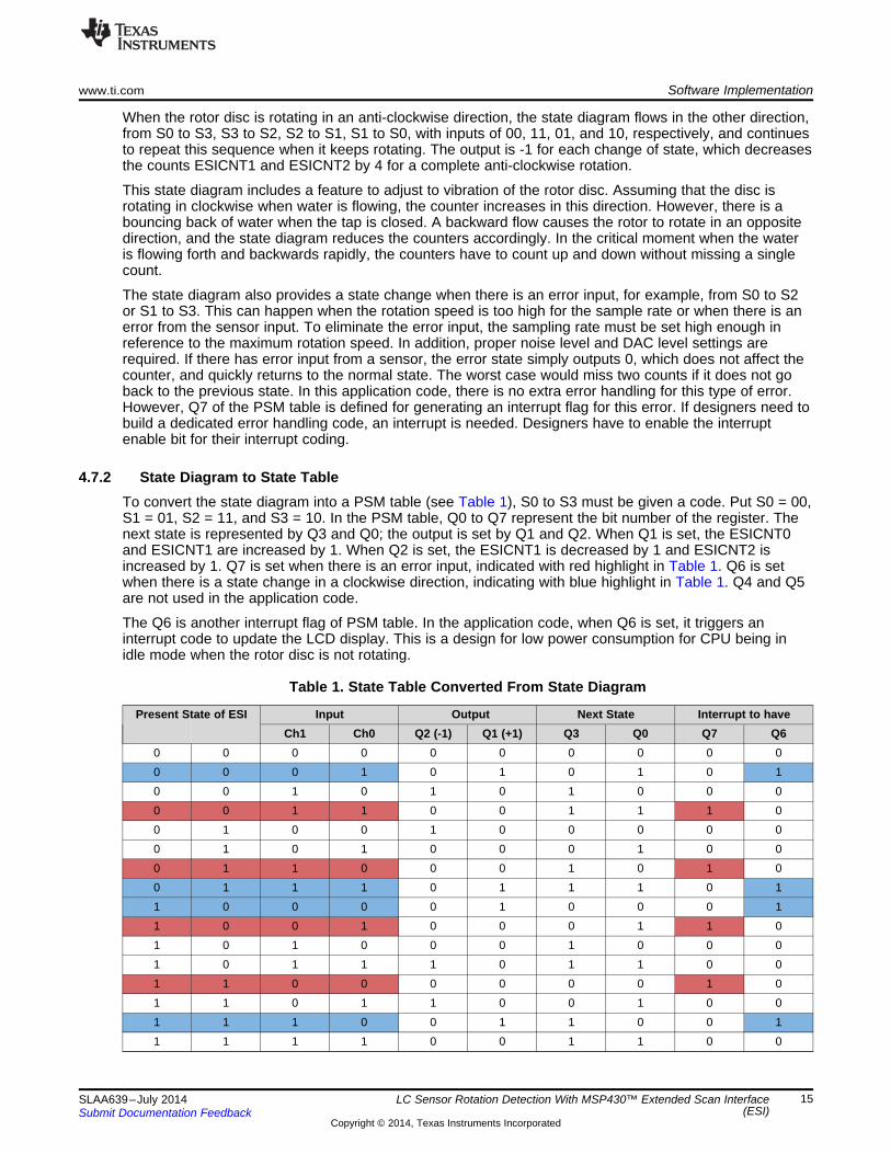
4.7.2 State Diagram to State TableTo convert the state diagram into a PSM table (see Table 1), S0 to S3 must be given a code. Put S0 = 00,S1 = 01, S2 = 11, and S3 = 10. In the PSM table, Q0 to Q7 represent the bit number of the register. Thenext state is represented by Q3 and Q0; the output is set by Q1 and Q2. When Q1 is set, the ESICNT0and ESICNT1 are increased by 1. When Q2 is set, the ESICNT1 is decreased by 1 and ESICNT2 isincreased by 1. Q7 is set when there is an error input, indicated with red highlight in Table 1. Q6 is setwhen there is a state change in a clockwise direction, indicating with blue highlight in Table 1. Q4 and Q5are not used in the application code.
The Q6 is another interrupt flag of PSM table. In the application code, when Q6 is set, it triggers aninterrupt code to update the LCD display. This is a design for low power consumption for CPU being inidle mode when the rotor disc is not rotating.
Table 1. State Table Converted From State Diagram
Present State of ESI Input Output Next State Interrupt to haveCh1 Ch0 Q2 (-1) Q1 (+1) Q3 Q0 Q7 Q6
0 0 0 0 0 0 0 0 0 00 0 0 1 0 1 0 1 0 10 0 1 0 1 0 1 0 0 00 0 1 1 0 0 1 1 1 00 1 0 0 1 0 0 0 0 00 1 0 1 0 0 0 1 0 00 1 1 0 0 0 1 0 1 00 1 1 1 0 1 1 1 0 11 0 0 0 0 1 0 0 0 11 0 0 1 0 0 0 1 1 01 0 1 0 0 0 1 0 0 01 0 1 1 1 0 1 1 0 01 1 0 0 0 0 0 0 1 01 1 0 1 1 0 0 1 0 01 1 1 0 0 1 1 0 0 11 1 1 1 0 0 1 1 0 0
Software Implementation www.ti.com
16 SLAA639–July 2014Submit Documentation Feedback
Copyright © 2014, Texas Instruments Incorporated
LC Sensor Rotation Detection With MSP430™ Extended Scan Interface(ESI)
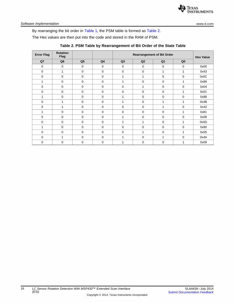
By rearranging the bit order in Table 1, the PSM table is formed as Table 2.
The Hex values are then put into the code and stored in the RAM of PSM.
Table 2. PSM Table by Rearrangement of Bit Order of the State Table
Error Flag RotationFlag Rearrangement of Bit Order
Hex ValueQ7 Q6 Q5 Q4 Q3 Q2 Q1 Q00 0 0 0 0 0 0 0 0x000 1 0 0 0 0 1 1 0x430 0 0 0 1 1 0 0 0x0C1 0 0 0 1 0 0 1 0x890 0 0 0 0 1 0 0 0x040 0 0 0 0 0 0 1 0x011 0 0 0 1 0 0 0 0x880 1 0 0 1 0 1 1 0x4B0 1 0 0 0 0 1 0 0x421 0 0 0 0 0 0 1 0x810 0 0 0 1 0 0 0 0x080 0 0 0 1 1 0 1 0x0D1 0 0 0 0 0 0 0 0x800 0 0 0 0 1 0 1 0x050 1 0 0 1 0 1 0 0x4A0 0 0 0 1 0 0 1 0x09
www.ti.com Runtime Calibration With AFE2
17SLAA639–July 2014Submit Documentation Feedback
Copyright © 2014, Texas Instruments Incorporated
LC Sensor Rotation Detection With MSP430™ Extended Scan Interface(ESI)
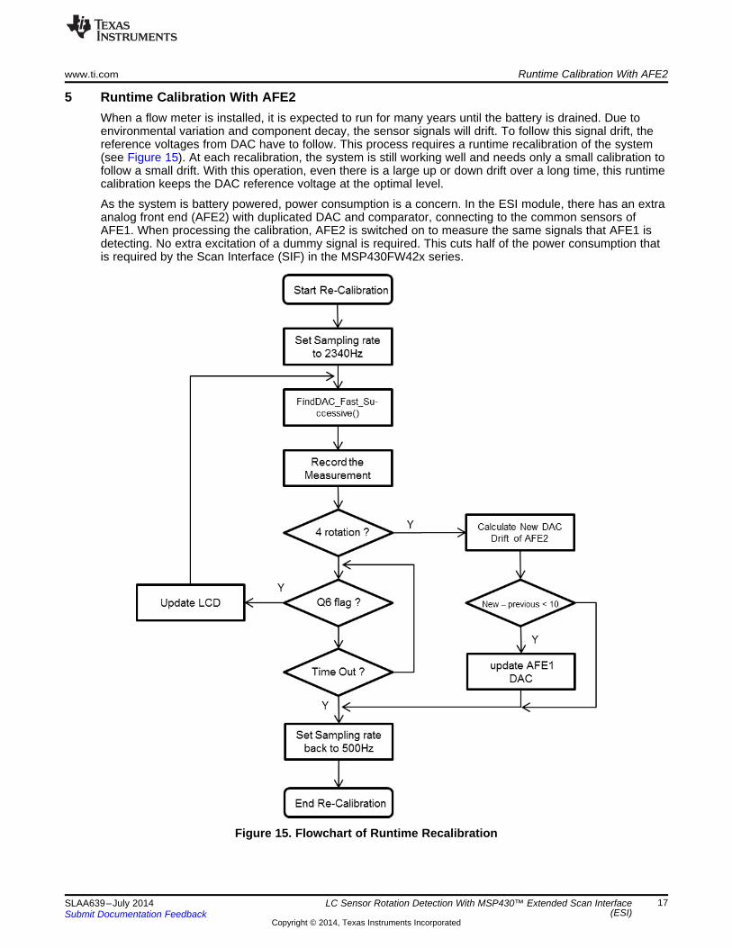
5 Runtime Calibration With AFE2When a flow meter is installed, it is expected to run for many years until the battery is drained. Due toenvironmental variation and component decay, the sensor signals will drift. To follow this signal drift, thereference voltages from DAC have to follow. This process requires a runtime recalibration of the system(see Figure 15). At each recalibration, the system is still working well and needs only a small calibration tofollow a small drift. With this operation, even there is a large up or down drift over a long time, this runtimecalibration keeps the DAC reference voltage at the optimal level.
As the system is battery powered, power consumption is a concern. In the ESI module, there has an extraanalog front end (AFE2) with duplicated DAC and comparator, connecting to the common sensors ofAFE1. When processing the calibration, AFE2 is switched on to measure the same signals that AFE1 isdetecting. No extra excitation of a dummy signal is required. This cuts half of the power consumption thatis required by the Scan Interface (SIF) in the MSP430FW42x series.
Figure 15. Flowchart of Runtime Recalibration

Runtime Calibration With AFE2 www.ti.com
18 SLAA639–July 2014Submit Documentation Feedback
Copyright © 2014, Texas Instruments Incorporated
LC Sensor Rotation Detection With MSP430™ Extended Scan Interface(ESI)
5.1 Operation of RecalibrationDuring the normal operation, there is a timer to activate the recalibration process. The timer intervalshould be set within a period during which a small drift expected. The designer can modify the constant"Time_to_Recal" to change the timing. The input clock for the timer is 32768 Hz.
When the process is activated, the MCU is in LPM3 mode until an interrupt is triggered by the Q6 flagfrom the PSM connected to AFE1. During recalibration, AFE1 continues normal operation, and AFE2 isturned on for signal level measurement. The Q6 flag is set only when the rotor disc is rotating in clockwisedirection and there is a change of state of a sensor. This ensures low-power operation duringrecalibration. See the flow chart of runtime recalibration in Figure 15.
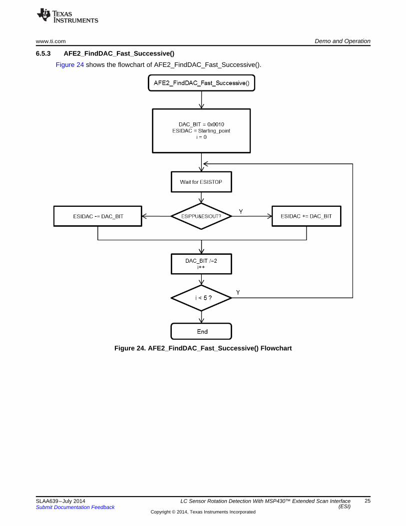
As the two sensors are located in 90° apart, one sensor must be located at the center of the metal ornonmetal area of the rotor disc when the other sensor detects a change of state by AFE1 (see Figure 16).Using this property, the signal level of this sensor is always the maximum or minimum. As this ismeasured with the rotor disc rotating, the measurement algorithm is required to be fast and timedeterministic. By using the function AFE2_FindDAC_Fast_Successive() for AFE2, the signal level can bemeasured in five measuring cycles. A faster sampling rate of 2340 Hz is required to make sure that thesensor under measurement is kept on the same side of the disc and the signal level remains in a constantlevel. For sampling rate setting, see the section of sampling rate.
Figure 16. Transition States Of A Sensor
Because AFE1 and AFE2 are both inside the single MCU, the environment is identical to both of them.When there is a drift in AFE2, there is a similar drift in AFE1. Therefore, when a drift is determined inAFE2, the new level of AFE1 can be added with the same level of drift.
After four complete rotations, the recorded measurements are used to calculate the drift of AFE2 and thenew DAC level of AFE1, as follows for channel 0. similar for channel 1.
AFE2_drift0 = (AFE2_Max_DAC_Ch0 + AFE2_Min_DAC_Ch0)/2 - AFE2_base0;New_level = AFE1_base0 + AFE2_drift0;Delta = (ESIDAC1R0+ESIDAC1R1)/2 - New_level;
If "Delta", the difference between the new level and previous level of DAC of AFE1, is less than 10, a validmeasurement is confirmed and the new DAC values are set for channel 0 of AFE1, as calculated in theseequations.
The designer can modify the condition value for a validation of measurement, but it cannot be larger thanthe half of the normal separation of maximum and minimum. If the condition exceeds this value, it can betreated as noise, because the ESI is still working during recalibration, and expects a small drift.
ESIDAC1R0 = New_level - Noise_level;ESIDAC1R1 = New_level + Noise_level;
After that, the recalibration is finished. The sampling rate is changed back to normal rate and the timerrestarts for the next calibration. There is a timeout timer of two seconds during the recalibration process. Ifthe rotor does not move for two seconds, the process times out, the sampling rate is changed back to thenormal rate, and the application waits for the next calibration.
www.ti.com Demo and Operation
19SLAA639–July 2014Submit Documentation Feedback
Copyright © 2014, Texas Instruments Incorporated
LC Sensor Rotation Detection With MSP430™ Extended Scan Interface (ESI)
6 Demo and Operation
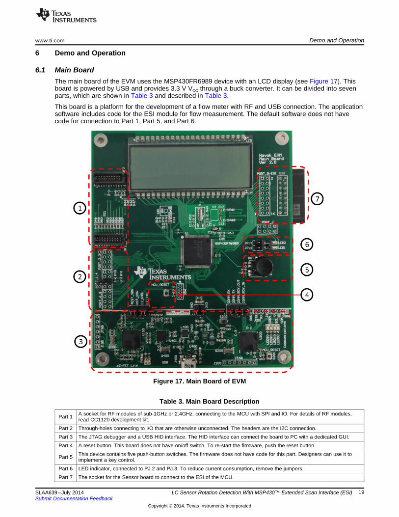
6.1 Main BoardThe main board of the EVM uses the MSP430FR6989 device with an LCD display (see Figure 17). Thisboard is powered by USB and provides 3.3 V VCC through a buck converter. It can be divided into sevenparts, which are shown in Table 3 and described in Table 3.
This board is a platform for the development of a flow meter with RF and USB connection. The applicationsoftware includes code for the ESI module for flow measurement. The default software does not havecode for connection to Part 1, Part 5, and Part 6.
Figure 17. Main Board of EVM
Table 3. Main Board Description
Part 1 A socket for RF modules of sub-1GHz or 2.4GHz, connecting to the MCU with SPI and IO. For details of RF modules,read CC1120 development kit.
Part 2 Through-holes connecting to I/O that are otherwise unconnected. The headers are the I2C connection.Part 3 The JTAG debugger and a USB HID interface. The HID interface can connect the board to PC with a dedicated GUI.Part 4 A reset button. This board does not have on/off switch. To re-start the firmware, push the reset button.
Part 5 This device contains five push-button switches. The firmware does not have code for this part. Designers can use it toimplement a key control.
Part 6 LED indicator, connected to PJ.2 and PJ.3. To reduce current consumption, remove the jumpers.Part 7 The socket for the Sensor board to connect to the ESI of the MCU.
Demo and Operation www.ti.com
20 SLAA639–July 2014Submit Documentation Feedback
Copyright © 2014, Texas Instruments Incorporated
LC Sensor Rotation Detection With MSP430™ Extended Scan Interface (ESI)
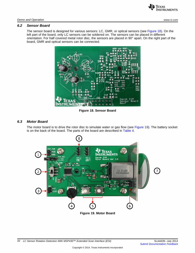
6.2 Sensor BoardThe sensor board is designed for various sensors: LC, GMR, or optical sensors (see Figure 18). On theleft part of the board, only LC sensors can be soldered on. The sensors can be placed in differentorientation. For half covered metal rotor disc, the sensors are placed in 90° apart. On the right part of theboard, GMR and optical sensors can be connected.
Figure 18. Sensor Board
6.3 Motor BoardThe motor board is to drive the rotor disc to simulate water or gas flow (see Figure 19). The battery socketis on the back of the board. The parts of the board are described in Table 4.
Figure 19. Motor Board
www.ti.com Demo and Operation
21SLAA639–July 2014Submit Documentation Feedback
Copyright © 2014, Texas Instruments Incorporated
LC Sensor Rotation Detection With MSP430™ Extended Scan Interface(ESI)
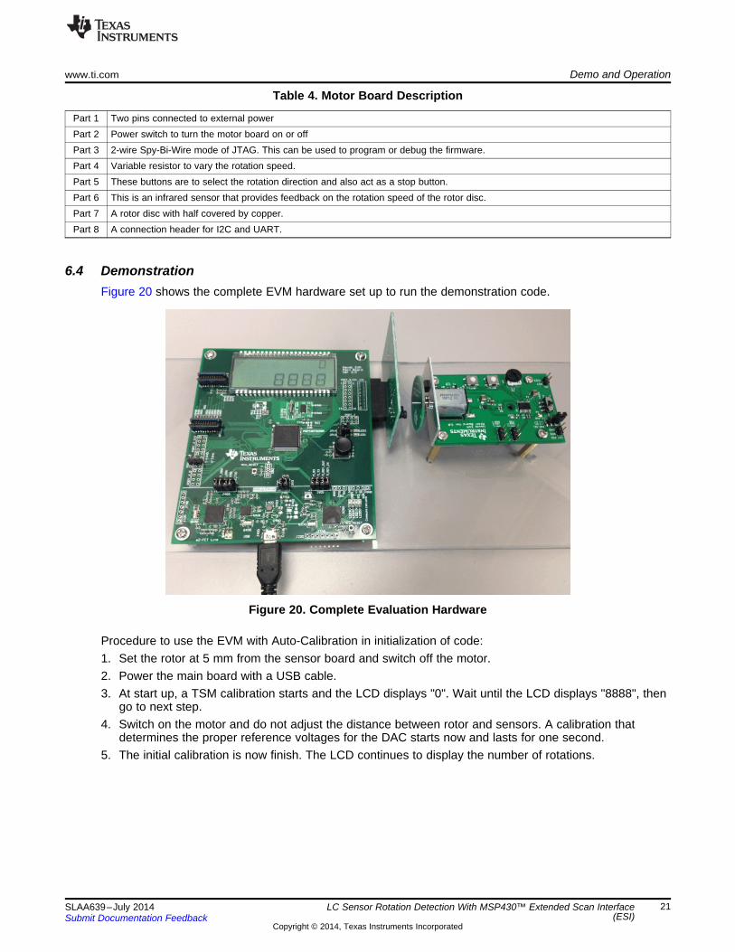
Table 4. Motor Board Description
Part 1 Two pins connected to external powerPart 2 Power switch to turn the motor board on or offPart 3 2-wire Spy-Bi-Wire mode of JTAG. This can be used to program or debug the firmware.Part 4 Variable resistor to vary the rotation speed.Part 5 These buttons are to select the rotation direction and also act as a stop button.Part 6 This is an infrared sensor that provides feedback on the rotation speed of the rotor disc.Part 7 A rotor disc with half covered by copper.Part 8 A connection header for I2C and UART.
6.4 DemonstrationFigure 20 shows the complete EVM hardware set up to run the demonstration code.
Figure 20. Complete Evaluation Hardware
Procedure to use the EVM with Auto-Calibration in initialization of code:1. Set the rotor at 5 mm from the sensor board and switch off the motor.2. Power the main board with a USB cable.3. At start up, a TSM calibration starts and the LCD displays "0". Wait until the LCD displays "8888", then
go to next step.4. Switch on the motor and do not adjust the distance between rotor and sensors. A calibration that
determines the proper reference voltages for the DAC starts now and lasts for one second.5. The initial calibration is now finish. The LCD continues to display the number of rotations.

Demo and Operation www.ti.com
22 SLAA639–July 2014Submit Documentation Feedback
Copyright © 2014, Texas Instruments Incorporated
LC Sensor Rotation Detection With MSP430™ Extended Scan Interface(ESI)
6.4.1 Current ConsumptionFigure 21 shows the current consumption of the MCU with two LC sensors, excluding the current into theLCD, power, and other modules on the board. The data is taken by measuring the current flowing into theMCU connected to two sensors with the LCD off, varying with different sampling rate in the SIF ofMSP430FW42x and the ESI of MSP430FR6989.
Figure 21. Current Consumption of ESI With Two Sensors
From the experimental data, the current consumption in MSP430FR6989 is half of that for aMSP430FW42x system with the same type of LC sensors.• For the MSP430FR6989 with two LC sensors, the current per sample is less than 9 nA.• For the MSP430FW42x with two LC sensors, the current per sample is less than 17 nA.
Current consumption of the MSP430FR6989 running the ESI without sensors is also given. This showsthat the LC sensors account for half of the total current consumption of the system. To further reduce thecurrent consumption, well designed LC sensors are necessary.

www.ti.com Demo and Operation
23SLAA639–July 2014Submit Documentation Feedback
Copyright © 2014, Texas Instruments Incorporated
LC Sensor Rotation Detection With MSP430™ Extended Scan Interface(ESI)
6.5 Signal Level Searching AlgorithmThere are two channels in the algorithm. For simplicity in the following flow charts, only the first channel isshown. The other channel is processed with the same algorithm.
6.5.1 FindDAC()Figure 22 shows the flowchart of FindDAC().
Figure 22. FindDAC() Flowchart

Demo and Operation www.ti.com
24 SLAA639–July 2014Submit Documentation Feedback
Copyright © 2014, Texas Instruments Incorporated
LC Sensor Rotation Detection With MSP430™ Extended Scan Interface(ESI)
6.5.2 FindDAC_Fast_Range()Figure 23 shows the flowchart of FindDAC_Fast_Range().
Figure 23. FindDAC_Fast_Range Flowchart
www.ti.com Demo and Operation
25SLAA639–July 2014Submit Documentation Feedback
Copyright © 2014, Texas Instruments Incorporated
LC Sensor Rotation Detection With MSP430™ Extended Scan Interface(ESI)
6.5.3 AFE2_FindDAC_Fast_Successive()Figure 24 shows the flowchart of AFE2_FindDAC_Fast_Successive().
Figure 24. AFE2_FindDAC_Fast_Successive() Flowchart
References www.ti.com
26 SLAA639–July 2014Submit Documentation Feedback
Copyright © 2014, Texas Instruments Incorporated
LC Sensor Rotation Detection With MSP430™ Extended Scan Interface(ESI)
7 References1. MSP430FR698x(1), MSP430FR598x(1) Mixed-Signal Microcontrollers (SLAS789)
2. MSP430FR58xx, MSP430FR59xx, MSP430FR68xx, and MSP430FR69xx Family User's Guide(SLAU367)
3. Code Composer Studio (CCSTUDIO) Version 5.5
4. Rotation Detection With the MSP430 Scan Interface (SLAA222)
5. SmartRF Transceiver Evaluation Board User's Guide (SWRU294)
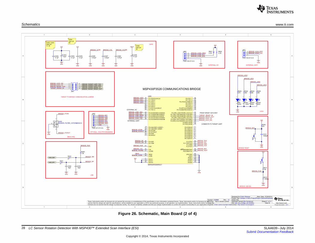
8 SchematicsThe following figures show the schematics of the main, sensor, and motor boards in the EVM430-FR6989.

1
1
2
2
3
3
4
4
5
5
6
6
D D
C C
B B
A A
1 4
27/05/2014
usb_hub_and_po wer_sch.SchDoc
Sheet Title:
Size:
Mod. Date:
File:Sheet: of
B http://www.ti.comContact: http://www.ti.com/support
Change in menu Project|Project Options|ParametersProject Title:Designed for:Public Release
Assembly Variant: [No Variations]
?Texas Instruments 2014
Drawn By:Engineer: Enter name of project lead
Texas Instruments and/or its licensors do not warrant the accuracy or completeness of this specification or any information contained therein. Texas Instruments and/or its licensors do notwarrant that this design will meet the specifications, will be suitable for your application or fit for any particular purpose, or will operate in an implementation. Texas Instruments and/or itslicensors do not warrant that the design is production worthy. You should completely validate and test your design implementation to confirm the system functionality for your application.
Not in version controlSVN Rev:XX####Number: Rev: E1
DP01
DM02
VCC3
RESET4
EECLK5
EEDATA/GANGED6
GND7
BUSPWR8
PWRON19
OVRCUR110
DM111
DP112
PWRON213
OVRCUR214
DM215
DP216
PWRON317
OVRCUR318
DM319
DP320
PWRON421
OVRCUR422
DM423
DP424
VCC25
EXTMEM26
TSTPLL/48MCLK27
GND28
XTAL229
XTAL130
TSTMODE31
SUSPND32
EP33
U401
TUSB2046BIRHBR
MODE1
SW2
VIN3
4
EN5
FB6
GND
U403TPS62237DRYR
VCC1
NC2
IO13
GND4
IO25
U400
TPD2E001DRLR
OUT1
N/C2
NR/FB3
GND4
EN5
N/C6
N/C7
IN8
PAD
U402
TPS73533DRB (DNP)
POWER SWITCHES
GND
GND
D-
D+
MICRO USB
0.1µFC402
GND
3V3
22pFC403
22pFC404
GNDGND
GND
GND
GND
DP0
DM0
3V3
0.1µFC400
GND
HUB RESET
HUB_RESET
HUB_RESET
DP0DM0
GND
DP4
DM4
DP3
DM3
HUB3 and HUB4 NOT USED
DP3DM3
DP4DM4
GND
6MHZ XTAL
1
2
3
Q400CSTCR4M00G15L99
GND
HUB_XTAL1
HUB_XTAL1
HUB_XTAL2
0.01µF (DNP)C416
GND GNDGND
OPTIONAL 3.3V LDO
3.3V BUCK REGULATOR
NC
THERMAL CONNECTION ONLY
NC
BUCK_3V3LDO_3V3
3V3
3V3
USB HUB
3V3
500mA LDO LDO_3V3
BUCK_3V3
10pFC405
10pFC406
GNDGND
EZFET USB HUB FILTER
HUB_DM2
HUB_DP2
GND GND
10pFC410
10pFC412
GNDGNDGND GND
HUB_DM1
HUB_DP1
DM1DP1
DM2DP2
DM2
DP2
DM1
DP1
BRIDGE USB HUB FILTER
GND
4.7µFC401
2.2µF (DNP)C418
1µF (DNP)C414
1µFC417
1µFC415
GND
0.1µFC407
0.1µFC408
GND
27
R406 HUB_XTAL2
USB_SHIELD
15.0kR410
15.0kR415
15.0kR414
15.0kR411
1.5kR408
33
R405
47kR404
15.0k
R403
15.0k
R402
15.0k
R401
15.0k
R400
10k (DNP)
R418
22
R413
22
R412
22
R417
22
R416
22
R407
22
R409
1
2
3
4
5
6
7
10
11
8
9
J400
ZX62R-B-5P
2.2µHL400
NR3010T2R2M
DNP
R419
0
R420
3V3
NC
NCNCNCNC
VBUS
VBUS
VBUS
Place 0.1uF as close toU400 vcc as possible.Also ensure sufficient metalfor Vcc and Gnd for ESDconduction.
www.ti.com Schematics
27SLAA639–July 2014Submit Documentation Feedback
Copyright © 2014, Texas Instruments Incorporated
LC Sensor Rotation Detection With MSP430™ Extended Scan Interface (ESI)
Figure 25. Schematic, Main Board (1 of 4)
1
1
2
2
3
3
4
4
5
5
6
6
D D
C C
B B
A A
2 4
27/05/2014
usb_mcu_bridge_sch.SchDoc
Sheet Title:
Size:
Mod. Date:
File:Sheet: of
B http://www.ti.comContact: http://www.ti.com/support
Change in menu Project|Project Options|ParametersProject Title:Designed for:Public Release
Assembly Variant: [No Variations]
?Texas Instruments 2014
Drawn By:Engineer: Enter name of project lead
Texas Instruments and/or its licensors do not warrant the accuracy or completeness of this specification or any information contained therein. Texas Instruments and/or its licensors do notwarrant that this design will meet the specifications, will be suitable for your application or fit for any particular purpose, or will operate in an implementation. Texas Instruments and/or itslicensors do not warrant that the design is production worthy. You should completely validate and test your design implementation to confirm the system functionality for your application.
Not in version controlSVN Rev:XX####Number: Rev: E1
P6.0/CB0/A01
P6.1/CB1/A12
P6.2/CB2/A23
P6.3/CB3/A34
P6.4/CB4/A45
P6.5/CB5/A56
P6.6/CB6/A67
P6.7/CB7/A78
P5.0/A8/VREF+/VEREF+9
P5.1/A9/VREF-/VEREF-10
AVCC111
P5.4/XIN12
P5.5/XOUT13
AVSS114
DVCC115
DVSS116
VCORE17
P1.0/TA0CLK/ACLK18
P1.1/TA0.019
P1.2/TA0.120
P1.3/TA0.221
P1.4/TA0.322
P1.5/TA0.423
P1.6/TA1CLK/CBOUT24
P1.7/TA1.025
P2.0/TA1.126
P2.1/TA1.227
P2.2/TA2CLK/SMCLK28
P2.3/TA2.029
P2.4/TA2.130
P2.5/TA2.231
P2.6/RTCCLK/DMAE032
P2.7/UCB0STE/UCA0CLK33
P3.0/UCB0SIMO/UCB0SDA34
P3.1/UCB0SOMI/UCB0SCL35
P3.2/UCB0CLK/UCA0STE36
P3.3/UCA0TXD/UCA0SIMO37
P3.4/UCA0RXD/UCA0SOMI38
DVSS239
DVCC240
P4.0/PM_UCB1STE/PM_UCA1CLK41
P4.1/PM_UCB1SIMO/PM_UCB1SDA42
P4.2/PM_UCB1SOMI/PM_UCB1SCL43
P4.3/PM_UCB1CLK/PM_UCA1STE44
P4.4/PM_UCA1TXD/PM_UCA1SIMO45
P4.5/PM_UCA1RXD/PM_UCA1SOMI46
P4.6/PM_NONE47
P4.7/PM_NONE48
VSSU49
PU.0/DP50
PUR51
PU.1/DM52
VBUS53
VUSB54
V1855
AVSS256
P5.2/XT2IN57
P5.3/XT2OUT58
TEST/SBWTCK59
PJ.0/TDO60
PJ.1/TDI/TCLK61
PJ.2/TMS62
PJ.3/TCK63
RST/NMI/SBWTDIO64
QFN PAD65
U200
MSP430F5528IRGCT
BRIDGE_DM
BRIDGE_DP
10pFC200
10pFC201
GNDGNDUSB
4MHZ XTAL
1
2
3
Q200MURATA -FILTER_CSTCR4M00G15
GND
BRIDGE_XT2IN
BRIDGE_XT2OUT
3V3
GND
CAPS
0.1µFC205
GND
3V3
0.1µFC202
0.22µFC206
GND
BRIDGE_VUSB
0.47µFC208
0.22µFC207
GND GND
BRIDGE_V18 BRIDGE_VCORE
BRIDGE_DMBRIDGE_DP
3V3
GND GND
VBUS
VBUSBRIDGE_VUSB
BRIDGE_V18BRIDGE_VCORE
3V3
GNDBRIDGE USB BSL
BRIDGE_PUR
BRIDGE_PUR
3V3
1000pFC210
GNDBRIDGE RESET
BRIDGE_PUR
EXTERNAL UART
BRIDGE_XT2INBRIDGE_XT2OUT
EXTERNAL I2C
BRIDGE_TDOBRIDGE_TDIBRIDGE_TMSBRIDGE_TCK
CONNECTS TO TARGET UART
FROM TARGET DATA RDYLEDS
Green
12
D201
GND
BRIDGE_LED0
BRIDGE_LED1
Green
12
D203
BRIDGE_LED2
BRIDGE_LED3
BRIDGE_LED0BRIDGE_LED1BRIDGE_LED2BRIDGE_LED3
HUB_DM1
HUB_DP1
MSP430F5528 COMMUNICATIONS BRIDGE
10µFC203
4.7µFC209
0.1µFC204
1
2
3
J201
TSW-103-07-G-S
BRIDGE_UCA0_RXDBRIDGE_UCA0_TXD
EXTERNAL UART
GND
BRIDGE_UCA0_RXDBRIDGE_UCA0_TXD
OPTIONAL JTAG PROGRAMMING
BRIDGE_RSTBRIDGE_TEST
BRIDGE_RST
Red
12
D200Green
12
D202
47kR209
100R211
1.0MegR210
27
R203
27
R201
1.5kR206
390R202
390R204
390R205
470R200
BRIDGE_TARGET_READY_OUT
1 2
3 4
5 6
7 8
J601
BRIDGE_TARGET_UART_RXD
BRIDGE_TARGET_UART_TXD
TARGET TO BRIDGE COMMUNICATION JUMPER
BRIDGE_TARGET_READY_IN
EXTERNAL I2C
2.2KR601
2.2KR600
3V3
GND
GNDBRIDGE_TESTBRIDGE_TDOBRIDGE_TDIBRIDGE_TMSBRIDGE_TCKBRIDGE_RST
5
4
1
2
3
6
7
J200
TSW-107-07-G-SGND
BRIDGE_UCB0_SCLBRIDGE_UCB0_SDA
BRIDGE_UCB0_SDABRIDGE_UCB0_SCL
TARGET_READY_INBRIDGE_READY_OUTBRIDGE_UCA1_TXBRIDGE_UCA1_RX
BRIDGE_UCA1_TXBRIDGE_UCA1_RX
BRIDGE_READY_OUTTARGET_READY_IN
4
1
2
3
J600
TSW-104-07-G-S
BRIDGE_UCB0_DRDY
BRIDGE_UCB0_DRDY
S201
S202
C202, C203near pin11,15
C204near pin40
C208near pin53
Schematics www.ti.com
28 SLAA639–July 2014Submit Documentation Feedback
Copyright © 2014, Texas Instruments Incorporated
LC Sensor Rotation Detection With MSP430™ Extended Scan Interface (ESI)
Figure 26. Schematic, Main Board (2 of 4)
1
1
2
2
3
3
4
4
5
5
6
6
D D
C C
B B
A A
3 4
27/05/2014
ezFET_lite_sch.SchDoc
Sheet Title:
Size:
Mod. Date:
File:Sheet: of
B http://www.ti.comContact: http://www.ti.com/support
Change in menu Project|Project Options|ParametersProject Title:Designed for:Public Release
Assembly Variant: [No Variations]
?Texas Instruments 2014
Drawn By:Engineer: Enter name of project lead
Texas Instruments and/or its licensors do not warrant the accuracy or completeness of this specification or any information contained therein. Texas Instruments and/or its licensors do notwarrant that this design will meet the specifications, will be suitable for your application or fit for any particular purpose, or will operate in an implementation. Texas Instruments and/or itslicensors do not warrant that the design is production worthy. You should completely validate and test your design implementation to confirm the system functionality for your application.
Not in version controlSVN Rev:XX####Number: Rev: E1
P6.0/CB0/A01
P6.1/CB1/A12
P6.2/CB2/A23
P6.3/CB3/A34
P6.4/CB4/A45
P6.5/CB5/A56
P6.6/CB6/A67
P6.7/CB7/A78
P5.0/A8/VREF+/VEREF+9
P5.1/A9/VREF-/VEREF-10
AVCC111
P5.4/XIN12
P5.5/XOUT13
AVSS114
DVCC115
DVSS116
VCORE17
P1.0/TA0CLK/ACLK18
P1.1/TA0.019
P1.2/TA0.120
P1.3/TA0.221
P1.4/TA0.322
P1.5/TA0.423
P1.6/TA1CLK/CBOUT24
P1.7/TA1.025
P2.0/TA1.126
P2.1/TA1.227
P2.2/TA2CLK/SMCLK28
P2.3/TA2.029
P2.4/TA2.130
P2.5/TA2.231
P2.6/RTCCLK/DMAE032
P2.7/UCB0STE/UCA0CLK33
P3.0/UCB0SIMO/UCB0SDA34
P3.1/UCB0SOMI/UCB0SCL35
P3.2/UCB0CLK/UCA0STE36
P3.3/UCA0TXD/UCA0SIMO37
P3.4/UCA0RXD/UCA0SOMI38
DVSS239
DVCC240
P4.0/PM_UCB1STE/PM_UCA1CLK41
P4.1/PM_UCB1SIMO/PM_UCB1SDA42
P4.2/PM_UCB1SOMI/PM_UCB1SCL43
P4.3/PM_UCB1CLK/PM_UCA1STE44
P4.4/PM_UCA1TXD/PM_UCA1SIMO45
P4.5/PM_UCA1RXD/PM_UCA1SOMI46
P4.6/PM_NONE47
P4.7/PM_NONE48
VSSU49
PU.0/DP50
PUR51
PU.1/DM52
VBUS53
VUSB54
V1855
AVSS256
P5.2/XT2IN57
P5.3/XT2OUT58
TEST/SBWTCK59
PJ.0/TDO60
PJ.1/TDI/TCLK61
PJ.2/TMS62
PJ.3/TCK63
RST/NMI/SBWTDIO64
QFN PAD65
U100
MSP430F5528IRGCR
GND
47kR106
150kR109
1.5kR103
1.0MegR102
VBUS
GND
3V3
1000pFC111
GND
EZFET_VREF
EZFET_V18
EZFET_VUSB
EZFET_AVBUS
33pFC110
EZFET_AVCCOUT2ADC
EZFET_DPEZFET_DM
EZFET_PUR
EZFET_TDOEZFET_TDIEZFET_TMSEZFET_TCK
EZFET_TEST
GND
EZFET_DM
EZFET_DP
GNDEZFET_TESTEZFET_TDOEZFET_TDIEZFET_TMSEZFET_TCKEZFET_RST
3V3
GND
33pFC109
TARGET VCC SENSE
EZFET_AVCCOUT2ADC
EZFET_AVBUS
VBUS SENSE
EZFET_PROGRAM/DEBUG
EZFET_RST
EZFET RESET
EZFET_RST
LEDS4MHZ XTAL
470R104
390R105
Green
12
D101Red
12
D100
GND
EZFET_LED0
EZFET_LED1
EZFET_LED0EZFET_LED1
1
2
3
Q100
GND
EZFET_XT2IN
EZFET_XT2OUT
EZFET_XT2INEZFET_XT2OUT
CAPS
GND
3V3
0.1µFC102
3V3
0.22µFC105
GND
EZFET_VUSB
0.47µFC107
0.22µFC106
GND GND
EZFET_V18 EZFET_VCORE
EZFET_VCORE
0.1µFC108
GND
EZFET_VREF
27
R100
10pFC100
27
R101
10pFC101
GNDGNDUSB
EZFET_PUR
HUB_DM2
HUB_DP2
MSP430F5528 EZFET-LITE
0.1µFC10410µF
C103
240kR110
220kR108
220kR107
5
4
1
2
3
6
7
J100
TSW-107-07-G-S
EZFET
EZFET_TARGET_TEST_SBWTCK
EZFET_TARGET_RST_SBWTDIO
EZFET_TARGET_UART_RXD
EZFET_TARGET_UART_TXD
GND TARGET_GND
3V3
TARGET_3V3
10µFC409
1µFC411
EZFET_UART_TXDEZFET_UART_RXD
EZFET_UART_RXDEZFET_UART_TXD
EZFET_SBW_RST
EZFET_SBW_RSTEZFET_SBW_TST
EZFET_SBW_TST 1 2
3 4
5 6
7 8
J402
1 2
3 4
J401
TSW-102-07-G-D
VBUS
www.ti.com Schematics
29SLAA639–July 2014Submit Documentation Feedback
Copyright © 2014, Texas Instruments Incorporated
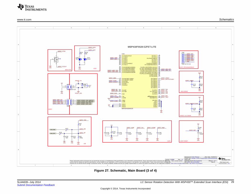
LC Sensor Rotation Detection With MSP430™ Extended Scan Interface (ESI)
Figure 27. Schematic, Main Board (3 of 4)

1
1
2
2
3
3
4
4
5
5
6
6
D D
C C
B B
A A
4 4
27/05/2014
MCU.SchDoc
Sheet Title:
Size:
Mod. Date:
File:Sheet: of
C http://www.ti.comContact: http://www.ti.com/support
Change in menu Project|Project Options|ParametersProject Title:Designed for: Public Release
Assembly Variant: [No Variations]
© Texas Instruments 2014
Drawn By:Engineer: Enter name of project lead
Texas Instruments and/or its licensors do not warrant the accuracy or completeness of this specification or any information contained therein. Texas Instruments and/or its licensors do notwarrant that this design will meet the specifications, will be suitable for your application or fit for any particular purpose, or will operate in an implementation. Texas Instruments and/or itslicensors do not warrant that the design is production worthy. You should completely validate and test your design implementation to confirm the system functionality for your application.
Not in version controlSVN Rev:XX####Number: Rev: E1
DNPR11
DNPR12
DNPR13
4u7C33
DNPVR1
TARGET_GND
TARGET_GND
0.1uF
C9
TARGET_3V3
TARGET_ GND
AGND
22pFC10
22pFC11
1 2
X2 DNP
DNFC12
DNFC13
AGND AGND
0.1uF
C7
0.1uF
C5
TARGET_GND
0.1uFC3
TARGET_3V3
TARGET_ GND
TARGET_3V3
AVCC
DNPR62
DNPR61
DNPR60
DNPR59
DNPC34
DNPC35
DNP
R63
TARGET_GND
AGNDTARGET_GND
P2.0/UCA0SIMO/UCA0TXD/TB0.6/TB0CLK51
P7.0/TA0CLK/S1752
P7.1/TA0.0/S1653
P7.2/TA0.1/S1554
P7.3/TA0.2/S1455
P7.4/SMCLK/S1356
DVSS257
DVCC258
P8.4/A7/C759
P8.5/A6/C660
P8.6/A5/C561
P8.7/A4/C462
P1.3/ESITEST4/TA1.2/A3/C363
P1.2/TA1.1/TA0CLK/COUT/A2/C264
P1.1/TA0.2/TA1CLK/COUT/A1/C1/VREF+/VeREF+65
P1.0/TA0.1/DMAE0/RTCCLK/A0/C0/VREF-/VeREF66
P9.0/ESICH0/ESITEST0/A8/C867
P9.1/ESICH1/ESITEST1/A9/C968
P9.2/ESICH2/ESITEST2/A10/C1069
P9.3/ESICH3/ESITEST3/A11/C1170
P9.4/ESICI0/A12/C1271
P9.5/ESICI1/A13/C1372
P9.6/ESICI2/A14/C1473
P9.7/ESICI3/A15/C1574
ESIVCC75
ES
IVS
S76
ES
ICI
77
ES
ICO
M78
AV
CC
179
AV
SS
380
PJ.7
/HF
XO
UT
81
PJ.6
/HF
XIN
82
AV
SS
183
PJ.4
/LF
XIN
84
PJ.5
/LF
XO
UT
85
AV
SS
286
P5.4
/UC
A1S
IMO
/UC
A1T
XD
/S12
87
P5
.5/U
CA
1S
OM
I/U
CA
1R
XD
/S11
88
P5
.6/U
CA
1C
LK
/S10
89
P5
.7/U
CA
1S
TE
/TB
0C
LK
/S9
90
P4
.4/U
CB
1S
TE
/TA
1C
LK
/S8
91
P4
.5/U
CB
1C
LK
/TA
1.0
/S7
92
P4
.6/U
CB
1S
IMO
/UC
B1
SD
A/T
A1.1
/S6
93
P4.7
/UC
B1S
OM
I/U
CB
1S
CL/T
A1.2
/S5
94
P1
0.0
/SM
CL
K/S
495
P4.0
/UC
B1S
IMO
/UC
B1S
DA
/MC
LK
/S3
96
P4.1
/UC
B1S
OM
I/U
CB
1S
CL
/AC
LK
/S2
97
DV
SS
398
DV
CC
399
P4.2
/UC
A0S
IMO
/UC
A0T
XD
/UC
B1C
LK
100
DV
SS
126
DV
CC
127
TE
ST
/SB
WT
CK
28
RE
SE
T/N
MI/S
BW
TD
IO29
PJ.0
/TD
O/T
B0
OU
TH
/SM
CL
K/S
RS
CG
130
PJ.1
/TD
I/T
CLK
/MC
LK
/SR
SC
G0
31
PJ.2
/TM
S/A
CLK
/SR
OS
CO
FF
32
PJ.3
/TC
K/C
OU
T/S
RC
PU
OF
F33
P6
.7/T
A0C
LK
/S3
134
P7
.5/T
A0.2
/S3
035
P7
.6/T
A0.1
/S2
936
P1
0.1
/TA
0.0
/S28
37
P7
.7/T
A1.2
/TB
0O
UT
H/S
27
38
P3
.3/T
A1.1
/TB
0C
LK
/S26
39
P3
.4/U
CA
1S
IMO
/UC
A1
TX
D/T
B0.0
/S25
40
P3
.5/U
CA
1S
OM
I/U
CA
1R
XD
/TB
0.1
/S24
41
P3
.6/U
CA
1C
LK
/TB
0.2
/S2
342
P3
.7/U
CA
1S
TE
/TB
0.3
/S22
43
P8
.0/R
TC
CLK
/S21
44
P8
.1/D
MA
E0
/S20
45
P8
.2/S
19
46
P8
.3/M
CLK
/S18
47
P2
.3/U
CA
0S
TE
/TB
0O
UT
H48
P2
.2/U
CA
0C
LK
/TB
0.4
/RT
CC
LK
49
P2
.1/U
CA
0S
OM
I/U
CA
0R
XD
/TB
0.5
/DM
AE
050
P4.3/UCA0SOMI/UCA0RXD#/UCB1STE1
P1.4/UCB0CLK/UCA0STE/TA1.0/S12
P1.5/UCB0STE/UCA0CLK/TA0.0/S03
P1.6/UCB0SIMO/UCB0SDA/TA0.14
P1.7/UCB0SOMI/UCB0SCL/TA0.25
R33/LCDCAP6
P6.0/R237
P6.1/R13/LCDREF8
P6.2/COUT/R039
P6.3/COM010
P6.4/TB0.0/COM111
P6.5/TB0.1/COM212
P6.6/TB0.2/COM313
P2.4/TB0.3/COM4/S4314
P2.5/TB0.4/COM5/S4215
P2.6/TB0.5/COM6/S4116
P2.7/TB0.6/COM7/S4017
P10.2/TA1.0/SMCLK/S3918
P5.0/TA1.1/MCLK/S3819
P5.1/TA1.2/S3720
P5.2/TA1.0/TA1CLK/ACLK/S3621
P5.3/UCB1STE/S3522
P3.0/UCB1CLK/S3423
P3.1/UCB1SIMO/UCB1SDA/S3324
P3.2/UCB1SOMI/UCB1SCL/S3225
U1MSP430FR6989
AGNDAGND
X132.768
NT0
Net-Tie
47KR1
2.2nFC1
MC
U_R
ES
ET
TARGET_GND
TARGET_3V3
5K6R5
5K6R6
5K6R7
5K6R8
100KR3
TARGET_3V3
11
22
33
44
55
66
77
88
99
10
10
11
11
12
12
13
13
14
14
15
15
16
16
17
17
18
18
19
19
20
20
21
21
22
22
23
23
24
24
CO
M3
25
CO
M2
26
CO
M1
27
CO
M0
28
29
29
30
30
31
31
32
32
33
33
34
34
35
35
36
36
37
37
38
38
39
39
40
40
41
41
42
42
43
43
44
44
LCD LCD
LCDFH-1152P
LED1
470RR9
LED2
470RR10
TARGET_3V3
1 2
JP13
1 2
JP14
1
2
3
4
5
6
SBW
Header 6
TARGET_GND
UART0_TXD
UART0_RXD
TEST/SBWTCKRST/NMI/SBWTDIO
RST/NMI/SBWTDIO
LC
D0
LC
D1
LC
D2
LC
D3
LC
D4
LC
D5
LC
D6
LC
D7
LC
D8
LC
D9
LC
D1
0L
CD
11
LC
D1
2L
CD
13
LC
D1
4L
CD
15
LC
D1
6L
CD
17
LC
D1
8L
CD
19
LC
D2
0L
CD
21
LC
D22
LC
D23
LC
D24
LC
D25
LC
D26
LC
D27
LC
D28
LC
D29
LC
D30
LC
D32
LC
D33
LC
D34
LC
D35
LC
D36
LC
D37
LC
D38
LC
D39
LC
D31
CO
M0
CO
M1
CO
M2
CO
M3
LCD28LCD29LCD30LCD31LCD32LCD33LCD34LCD35LCD36LCD37LCD38LCD39
COM0COM1COM2COM3
LCD0LCD1
LC
D2
LC
D3
LC
D4
LC
D5
LC
D6
LC
D7
LC
D8
LC
D9
LC
D1
0L
CD
11
LC
D1
2
LCD13LCD14LCD15LCD16LCD17
LC
D1
8L
CD
19
LC
D2
0L
CD
21
LC
D2
2L
CD
23
LC
D2
4L
CD
25
LC
D2
6L
CD
27
TE
ST
/SB
WT
CK
RS
T/N
MI/S
BW
TD
IOP
J.0
LE
D1
LE
D2
BUT_AIN
BUT_AIN
ESITEST4
ESICI0ESICI1ESICI2ESICI3
ESICH1/ESITEST1ESICH2/ESITEST2ESICH3/ESITEST3
ESICH0/ESITEST0
ESICOM
ESIVSS
ESIVCC
ES
IVS
SE
SIC
IE
SIC
OM
ESIVCC
LED1
LED2
UART0_RXD
UA
RT
0_
TX
D
I2C_SDAI2C_SCL
RF_RESETRF_GPIO_81RF_GPIO_10RF_GPIO_82
RF_GPIO_17RF_GPIO_13
RF_SPI1_MOSI/RF_UART_RXD
RF
_S
PI1
_M
ISO
/RF
_U
AR
T_
TX
DR
F_
SP
I1_S
CLK
RF
_S
PI1
_C
SN
RF
_S
PI_
CS
N
RF
_S
PI_
SC
LK
RF
_S
PI_
MIS
OR
F_
SP
I_M
OS
I
TARGET_3V3
10RR65
AVCC
EZFET_TA RGET_UART_RXD
EZFET_TA RGET_UART_TXD
BR
IDG
E_T
AR
GE
T_
RE
AD
Y_O
UT
BR
IDG
E_T
AR
GE
T_R
EA
DY
_IN
1 2
3 4
5 6
7 8
9 10
11 12
13 14
15 16
PORT_9/ESI
MHDR2X8
TARGET_GND
TARGET_3V3
ESIVCCESICIESICI2ESICI0ESICH2/ESITEST2ESICH0/ESITEST0ESITEST4
TARGET_GNDESIVSSESICOMESICI3ESICI1ESICH3/ESITEST3ESICH1/ESITEST1
1 2
3 4
5 6
7 8
9 10
11 12
13 14
15 16
ESI
MHDR2X8
TARGET_GND
TARGET_3V3
ESIVCCESICIESICI2ESICI0ESICH2/ESITEST2ESICH0/ESITEST0ESITEST4
TARGET_GNDESIVSSESICOMESICI3ESICI1ESICH3/ESITEST3ESICH1/ESITEST1
12
34
56
78
PORT_1_4
MHDR2X4
12
34
56
78
PORT_2_3
MHDR2X4
12
34
56
78
PORT_6_8
MHDR2X4
12
34
56
78
PORT_J
MHDR2X4
1 2
3 4
5 6
7 8
9 10
11 12
13 14
15 16
17 18
19 20
RF2
MHDR2X10
1 2
3 4
5 6
7 8
9 10
11 12
13 14
15 16
17 18
19 20
RF1
MHDR2X10
0.1uFC32
TARGET_GND
0RR440RR450RR46
0RR47
TARGET_GND
0RR480RR490RR500RR51
TARGET_GND
0RR570RR560RR550RR54
0RR530RR52
TARGET_3V3
RF_SPI1_CSNRF_GPIO_82RF_SPI1_MISO/RF_UART_TXDRF_SPI1_MOSI/RF_UART_RXD
RF_GPIO_17RF_GPIO_13
RF_SPI_CSNRF_SPI_SCLKRF_SPI_MOSIRF_SPI_MISO
RF_RESETRF_GPIO_81RF_GPIO_10
RF_SPI1_SCLK
LF
XO
UT
LF
XIN
HF
XO
UT
HF
XIN
PJ.0
PJ.1
PJ.1LED1LED2LFXINLFXOUTHFXINHFXOUTP6.0
P6.1P6.2
P6.0P6.1P6.2
RF_RESET RF_GPIO_81RF_GPIO_10 RF_GPIO_82
RF_SPI1_MOSI/RF_UART_RXDRF_SPI1_MISO/RF_UART_TXDRF_SPI1_SCLKRF_SPI1_CSN
RF_SPI_CSNRF_SPI_SCLKRF_SPI_MISORF_SPI_MOSI
RF_GPIO_17RF_GPIO_13
I2C_SDAI2C_SCLUART0_RXD UART0_TXD
P4.3P1.7
P1.0P1.1
P1.6P4.2
P2.0P2.1P2.2P2.3P3.4
P3.5 P3.6P3.7
P6.0P6.1P6.2P8.4P8.5P8.6P8.7
PJ.0PJ.1PJ.2PJ.3PJ.4PJ.5PJ.6PJ.7
EZFET_TA RGET_TEST_SBWTCK
EZFET_TA RGET_RST_SBWTDIO
BR
IDG
E_T
AR
GE
T_U
AR
T_R
XD
BR
IDG
E_T
AR
GE
T_U
AR
T_T
XD
0.1uF
C36
TARGET_GND
COM1
COM2
Up3
Down4
Select5
Right6
Left7
BUT
TARGET_GND
BUT_AIN
BUT_AIN2
BUT_AIN3
BUT_AIN4
BUT_AIN5
BUT_AIN2
BUT_AIN3
BUT_AIN4
BUT_AIN5 TARGET_GND
TARGET_GND TARGET_GND
DNP
R41
DNP
R40
TARGET_3V3
TARGET_3V3
Schematics www.ti.com
30 SLAA639–July 2014Submit Documentation Feedback
Copyright © 2014, Texas Instruments Incorporated
LC Sensor Rotation Detection With MSP430™ Extended Scan Interface (ESI)
Figure 28. Schematic, Main Board (4 of 4)

www.ti.com Schematics
31SLAA639–July 2014Submit Documentation Feedback
Copyright © 2014, Texas Instruments Incorporated
LC Sensor Rotation Detection With MSP430™ Extended Scan Interface (ESI)
Figure 29. Schematic, Sensor Board

Schematics www.ti.com
32 SLAA639–July 2014Submit Documentation Feedback
Copyright © 2014, Texas Instruments Incorporated
LC Sensor Rotation Detection With MSP430™ Extended Scan Interface (ESI)
Figure 30. Schematic, Motor Board
IMPORTANT NOTICE FOR TI DESIGN INFORMATION AND RESOURCES
Texas Instruments Incorporated (‘TI”) technical, application or other design advice, services or information, including, but not limited to,reference designs and materials relating to evaluation modules, (collectively, “TI Resources”) are intended to assist designers who aredeveloping applications that incorporate TI products; by downloading, accessing or using any particular TI Resource in any way, you(individually or, if you are acting on behalf of a company, your company) agree to use it solely for this purpose and subject to the terms ofthis Notice.TI’s provision of TI Resources does not expand or otherwise alter TI’s applicable published warranties or warranty disclaimers for TIproducts, and no additional obligations or liabilities arise from TI providing such TI Resources. TI reserves the right to make corrections,enhancements, improvements and other changes to its TI Resources.You understand and agree that you remain responsible for using your independent analysis, evaluation and judgment in designing yourapplications and that you have full and exclusive responsibility to assure the safety of your applications and compliance of your applications(and of all TI products used in or for your applications) with all applicable regulations, laws and other applicable requirements. Yourepresent that, with respect to your applications, you have all the necessary expertise to create and implement safeguards that (1)anticipate dangerous consequences of failures, (2) monitor failures and their consequences, and (3) lessen the likelihood of failures thatmight cause harm and take appropriate actions. You agree that prior to using or distributing any applications that include TI products, youwill thoroughly test such applications and the functionality of such TI products as used in such applications. TI has not conducted anytesting other than that specifically described in the published documentation for a particular TI Resource.You are authorized to use, copy and modify any individual TI Resource only in connection with the development of applications that includethe TI product(s) identified in such TI Resource. NO OTHER LICENSE, EXPRESS OR IMPLIED, BY ESTOPPEL OR OTHERWISE TOANY OTHER TI INTELLECTUAL PROPERTY RIGHT, AND NO LICENSE TO ANY TECHNOLOGY OR INTELLECTUAL PROPERTYRIGHT OF TI OR ANY THIRD PARTY IS GRANTED HEREIN, including but not limited to any patent right, copyright, mask work right, orother intellectual property right relating to any combination, machine, or process in which TI products or services are used. Informationregarding or referencing third-party products or services does not constitute a license to use such products or services, or a warranty orendorsement thereof. Use of TI Resources may require a license from a third party under the patents or other intellectual property of thethird party, or a license from TI under the patents or other intellectual property of TI.TI RESOURCES ARE PROVIDED “AS IS” AND WITH ALL FAULTS. TI DISCLAIMS ALL OTHER WARRANTIES ORREPRESENTATIONS, EXPRESS OR IMPLIED, REGARDING TI RESOURCES OR USE THEREOF, INCLUDING BUT NOT LIMITED TOACCURACY OR COMPLETENESS, TITLE, ANY EPIDEMIC FAILURE WARRANTY AND ANY IMPLIED WARRANTIES OFMERCHANTABILITY, FITNESS FOR A PARTICULAR PURPOSE, AND NON-INFRINGEMENT OF ANY THIRD PARTY INTELLECTUALPROPERTY RIGHTS.TI SHALL NOT BE LIABLE FOR AND SHALL NOT DEFEND OR INDEMNIFY YOU AGAINST ANY CLAIM, INCLUDING BUT NOTLIMITED TO ANY INFRINGEMENT CLAIM THAT RELATES TO OR IS BASED ON ANY COMBINATION OF PRODUCTS EVEN IFDESCRIBED IN TI RESOURCES OR OTHERWISE. IN NO EVENT SHALL TI BE LIABLE FOR ANY ACTUAL, DIRECT, SPECIAL,COLLATERAL, INDIRECT, PUNITIVE, INCIDENTAL, CONSEQUENTIAL OR EXEMPLARY DAMAGES IN CONNECTION WITH ORARISING OUT OF TI RESOURCES OR USE THEREOF, AND REGARDLESS OF WHETHER TI HAS BEEN ADVISED OF THEPOSSIBILITY OF SUCH DAMAGES.You agree to fully indemnify TI and its representatives against any damages, costs, losses, and/or liabilities arising out of your non-compliance with the terms and provisions of this Notice.This Notice applies to TI Resources. Additional terms apply to the use and purchase of certain types of materials, TI products and services.These include; without limitation, TI’s standard terms for semiconductor products http://www.ti.com/sc/docs/stdterms.htm), evaluationmodules, and samples (http://www.ti.com/sc/docs/sampterms.htm).
Mailing Address: Texas Instruments, Post Office Box 655303, Dallas, Texas 75265Copyright © 2017, Texas Instruments Incorporated