lc 120 (lhd) - toyota service information6898db2f-5765-41dd-a2ed...table of contents land cruiser...
TRANSCRIPT

TOYOTA MOTOR CORPORATIONPdf for ADPA N3LJ12/J-0-1.pdf
T O Y O T A N A V I G A T I O N S Y S T E M
EINBAUANLEITUNGINSTALLATION INSTRUCTIONS
INSTRUCTIONS D’INSTALLATION
TEILENUMMER - PART NUMBER - NUMERO DE PIECE
NAVIGATIONSSATZNAVIGATION KIT 08545-00805KIT DE NAVIGATION
FÜR - FOR - POUR
**J12*L
LC 120 (LHD)

PRECAUTIONS
• Be sure to disconnect the negative (-)lead from the battery terminals.
PLEASE READ THOROUGHLY THESEPRECAUTIONSFOR THIS SYSTEM INSTALLATION
• Do not pinch the rear wiring or har-ness in the tightened part.
• When passing the wires through thebulkhead or other panels, use a grom-met to ensure waterproofing.
• Protect the wiring with tape when it ispassed through a hole.
waterproof - O.K.!!
Grommet
Taping
• When disconnecting the connectors,be sure to grip the connector body.Do not tug on the wiring.
Stop it!
• Do not forcibly pull any car wiringharness. Rough tugging may result inopened connections, or a broken wireor harness.
• Confirm that lamps, horn, wiper andother car accessories operate normal-ly.
• Protect your car with wing covers,seat and so on.
• Use the correct tool when tighteningbolts or nuts.
• Before drilling a hole, check that therear of the mounting wall is clear.
• Be sure to firmly tighten connectorsand terminals.
Insertcompletely
• Before connecting the power wiring tothe battery, check the wiring connec-tions, harness, etc. to see that theyare properly secured.
• Check body and trim near area of installation to be cer-tain no dirt or scratches resulted from the installation.
LAND CRUISER (LHD) - 2
TNS 300LAND CRUISER
INSTALLATION PRECAUTIONS
Before installing:
1. Always make sure to disconnect the (-) battery cable.2. Place a cover on the vehicle to protect it from scratches or
damages during installation work.
Installation of parts:
1. Select a slit for installation work that does not impair opera-tion and offers adequate comfort,
2. Always check to make sure there are no objects present onthe reverse side when drilling mounting holes.
3. When tightening parts using bolts, nuts or other fasteners onthe vehicle, never attempt to use those involved in the steer-ing or brake systems.
4. When tightening parts, make sure not to pinch the wire har-ness on the reverse side.
Wiring:
1. Do not pull with excessive force on the vehicle’s wire har-ness. this can cause connectors to become disconnected ordamage to the wire harness.
2. Gather the wire harness of the vehicle together in a bundleso that they do not hang loose, and fasten in position usingclamps.
3. Do not pass wires through locations in contact with hot partsor parts that move in linking motion due to vibrations.
4. When passing wire through a hole, the lead wire must beprotected.
5. Make sure that connectors and terminals are securely con-nected.
6. When handling connectors, hold onto the connector with theconnector body and do not pull on the lead wire.

TABLE OF CONTENTS
LAND CRUISER (LHD) - 3
TNS 300LAND CRUISER
REMARK : Be sure to read the General Installation Instructions (Common Section) before installing TNS 300.
Precautions . . . . . . . . . . . . . . . . . . . . . . . . . . . . . . . . . . . . . . . . . . . . . . . . . . . . . . . . . . . . . . . . . . . . . . . 2
TNS 300 Navigation System Assy . . . . . . . . . . . . . . . . . . . . . . . . . . . . . . . . . . . . . . . . . . . . . . . . . . . . . . 4
How to Connect . . . . . . . . . . . . . . . . . . . . . . . . . . . . . . . . . . . . . . . . . . . . . . . . . . . . . . . . . . . . . . . . . . . 6
System Layout . . . . . . . . . . . . . . . . . . . . . . . . . . . . . . . . . . . . . . . . . . . . . . . . . . . . . . . . . . . . . . . . . . . . 5
Vehicle Disassembly . . . . . . . . . . . . . . . . . . . . . . . . . . . . . . . . . . . . . . . . . . . . . . . . . . . . . . . . . . . . . . . . 7
GPS Antenna Installation . . . . . . . . . . . . . . . . . . . . . . . . . . . . . . . . . . . . . . . . . . . . . . . . . . . . . . . . . . . . . 13
Wire Harness Installation . . . . . . . . . . . . . . . . . . . . . . . . . . . . . . . . . . . . . . . . . . . . . . . . . . . . . . . . . . . . . 15
Computer Installation . . . . . . . . . . . . . . . . . . . . . . . . . . . . . . . . . . . . . . . . . . . . . . . . . . . . . . . . . . . . . . . 20
System Start Up . . . . . . . . . . . . . . . . . . . . . . . . . . . . . . . . . . . . . . . . . . . . . . . . . . . . . . . . . . . . . . . . . . . 23
Final Check . . . . . . . . . . . . . . . . . . . . . . . . . . . . . . . . . . . . . . . . . . . . . . . . . . . . . . . . . . . . . . . . . . . . . . . 24

LAND CRUISER (LHD) - 4
TNS 300LAND CRUISER
TNS 300 NAVIGATION SYSTEM ASSY 08545-00805
4
32
8 9
1
5 6 7*1
10 11
NO. Description Qty
COMPUTER 1
WIRE HARNESS 1
GPS ANTENNA 1
NAVIGATION DISC (*1) 1
COMPUTER BRACKET 2
BOLT (M5 x 8) 4
CORD CLAMP 2
FOAM TAPE 2
WIRE TIE
EARTH PLATE 1
ADHESIVE TAPE 4
5
1
2
3
4
5
6
7
8
9
10
11
*1:NAVIGATION DISC (DVD-ROM) is not included in the navigation kit.4

LAND CRUISER (LHD) - 5
TNS 300LAND CRUISER
SYSTEM LAYOUTSYSTEM LAYOUT
Wire harness2
Antenna cordGPS antenna3
Computer1
Splicing connector (Reverse sensor wire)
Splicing connector (Speed sensor wire) Splicing connector (TX+ sensor wire)
Splicing connector (TX- sensor wire)
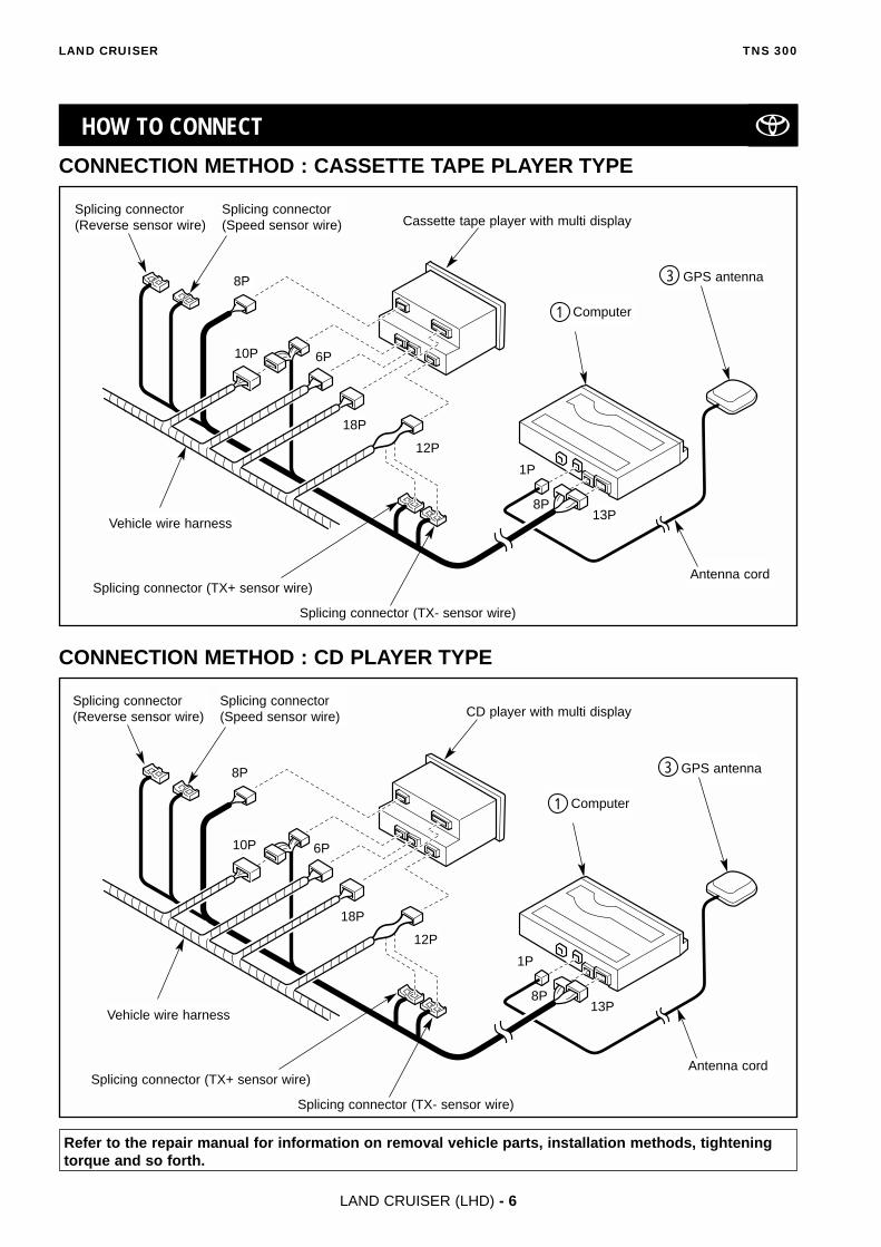
CONNECTION METHOD : CASSETTE TAPE PLAYER TYPE
CONNECTION METHOD : CD PLAYER TYPE
Refer to the repair manual for information on removal vehicle parts, installation methods, tighteningtorque and so forth.
TNS 300LAND CRUISER
LAND CRUISER (LHD) - 6
HOW TO CONNECT
Vehicle wire harness
Splicing connector(Speed sensor wire)
Splicing connector (TX+ sensor wire)
Splicing connector (TX- sensor wire)
Splicing connector(Reverse sensor wire)
10P
8P
18P
1P
13P8P
Antenna cord
GPS antenna3
Computer1
Cassette tape player with multi display
12P
6P
Vehicle wire harness
Splicing connector(Speed sensor wire)
Splicing connector (TX+ sensor wire)
Splicing connector (TX- sensor wire)
Splicing connector(Reverse sensor wire)
10P
8P
18P
1P
13P8P
Antenna cord
GPS antenna3
Computer1
CD player with multi display
12P
6P
LAND CRUISER (LHD) - 7
TNS 300LAND CRUISER
Figure 1
Figure 2
Figure 3
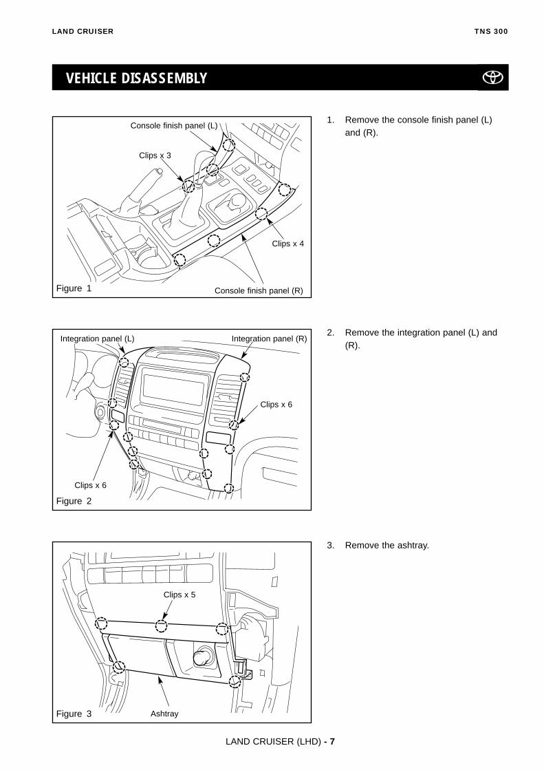
VEHICLE DISASSEMBLY
3. Remove the ashtray.
2. Remove the integration panel (L) and(R).
1. Remove the console finish panel (L) and (R).
Clips x 3
Console finish panel (R)
Clips x 6
Clips x 6
Integration panel (R)Integration panel (L)
Clips x 5
Ashtray
Clips x 4
Console finish panel (L)

LAND CRUISER (LHD) - 8
TNS 300LAND CRUISER
Figure X
Figure X
Figure X
Figure 4
Figure 5
Figure 6
6. Remove the cowl side panel (R).
5. Remove the front door scuff plate (R).
4. Remove the heater control panel.
Clips x 4
Heater control panel
Bolts x 5
Hooks x 11
Front door scuff plate (R)
Hooks x 2
Nut
Cowl side panel (R)
Bolt
LAND CRUISER (LHD) - 9
TNS 300LAND CRUISER
Figure X
Figure X
Figure X
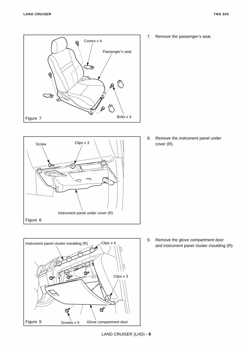
Figure 7
Figure 8
Figure 9 Screws x 5
9. Remove the glove compartment door and instrument panel cluster moulding (R).
8. Remove the instrument panel undercover (R).
7. Remove the passenger’s seat.
Bolts x 4
Passenger’s seat
Clips x 3Screw
Instrument panel under cover (R)
Clips x 4
Glove compartment door
Clips x 3
Instrument panel cluster moulding (R)
Covers x 4

LAND CRUISER (LHD) - 10
TNS 300LAND CRUISER
Figure X
Figure X
Figure X
10. Remove the foot rest.
11. Remove the front door scuff plate (L).
12. Remove the cowl side panel (L).
Figure 10
Figure 11
Figure 12
Foot rest
Clips x 2
Hooks x 11
Front door scuff plate (L)
Hooks x 2
Nut
Cowl side panel (L)

LAND CRUISER (LHD) - 11
TNS 300LAND CRUISER
Figure X
Figure X
Figure X
Figure 13
Figure 14
Figure 15
13. Remove the instrument panel undercover (L).
14. Remove the instrument panel clustermoulding (L).
15. Remove the ignition switch bezel andinstrument panel finish lower panel.
Clips x 2
Instrument panel cluster moulding (L)
Clips x 4
Bolts x 3
Instrument panel finish lower panel
Ignition switch bezel
Clips x 2
Screw
Instrument panel under cover (L)

LAND CRUISER (LHD) - 12
TNS 300LAND CRUISER
Figure X
Figure X
Figure 16
Figure 17
16. Remove the front console panel sidecover (R).
17. Remove the meter cluster panel.Clips x 2
Clips x 2
Meter cluster panel
Front console panel side cover (R)
Hooks x 2 Hook

LAND CRUISER (LHD) - 13
TNS 300LAND CRUISER
GPS ANTENNA INSTALLATION
Figure 18
FOAM TAPE CUT PROCEDURES
a) Cut the foam tape into 3 largepieces, 9 middle pieces and 12 smallpieces as shown in the illustration.
8
Foam tape8
<Large piece>• For computer• For computer corner cover
<Middle piece>• For wire harness & antenna cord routing• For extra length of reverse & speed
sensor wire
<Small piece>• For antenna cord routing• For reverse sensor wire routing• For speed sensor wire routing
Figure 19
ADHESIVE TAPE CUT PROCEDURES
a) Cut the adhesive tape into 1 largepieces and 2 small pieces as shown inthe illustration.
11
<Large piece>
• For bracket (Adhesive tape )
<Small piece>
• For earth plate (Adhesive tape )B
A
1. Using a knife, to cut off the weatherstrip of the antenna cord .
CAUTION : Be careful not to damagethe antenna cord .3
3GPS antenna 3
Weather strip
Knife
Figure 20
10mm
Adhesive tape11
x 1
x 2
x 3
x 9
x 12

LAND CRUISER (LHD) - 14
TNS 300LAND CRUISER
Figure 22
5. Route the antenna cord as shown inthe illustration.
6. Return the meter cluster to its originalposition, without rubbing GPS antenna
against the instrument panel.
CAUTION : Be careful not to slipaway GPS antenna from the earthplate .10
3
3
3
2. Remove the release paper of the earthplate and apply the adhesive tape .
3. Attach the earth plate to the metercluster panel as shown and mount theGPS antenna to the earth plate .
CAUTION : Make sure to clean theinstallation position surface beforeattaching the earth plate .
4. Fix the antenna cord using thefoam tapes .8
3
10
103
10
11
10
Figure 21
Adhesive tapes x 2 11
GPS antenna 3
Earth plate10
Antenna cord3
Foam tapes x 38
GPS antenna 3
Earth plate10Center
Meter cluster panel
B
Meter cluster panel
LAND CRUISER (LHD) - 15
TNS 300LAND CRUISER
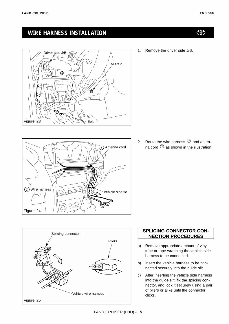
Figure 23
Figure 25
WIRE HARNESS INSTALLATION
2. Route the wire harness and anten-na cord as shown in the illustration.3
2
1. Remove the driver side J/B.
SPLICING CONNECTOR CON-NECTION PROCEDURES
a) Remove appropriate amount of vinyltube or tape wrapping the vehicle sideharness to be connected.
b) Insert the vehicle harness to be con-nected securely into the guide slit.
c) After inserting the vehicle side harnessinto the guide slit, fix the splicing con-nector, and lock it securely using a pairof pliers or alike until the connectorclicks.
Pliers
Splicing connector
Vehicle wire harness
Figure 24
Antenna cord3
Wire harness2
Bolt
Nut x 2
Driver side J/B
Vehicle side tie

LAND CRUISER (LHD) - 16
TNS 300LAND CRUISER
Figure 26
Figure 27
11
Figure 28
3. Route the speed sensor wire asshown in the illustration, and secure thespeed sensor wire using the foam tapes .8
2
4. Disconnect the 16P connector (White)
5. Connect the speed sensor wire (Violet /White) of the wire harness to the16P connector (White) terminal 11 har-ness.
6. Reconnect the 16P connector (white) todriver side J/B.
2
Driver side J/B
16P (White)
Foam tape x 38
Wire harness speed sensor wire2
Vehicle wire harness
16P (White)
Tab
Wire harness side 16P
Wire harness speed sensor wire (Violet / White)2
Splicing connector
LAND CRUISER (LHD) - 17
TNS 300LAND CRUISER
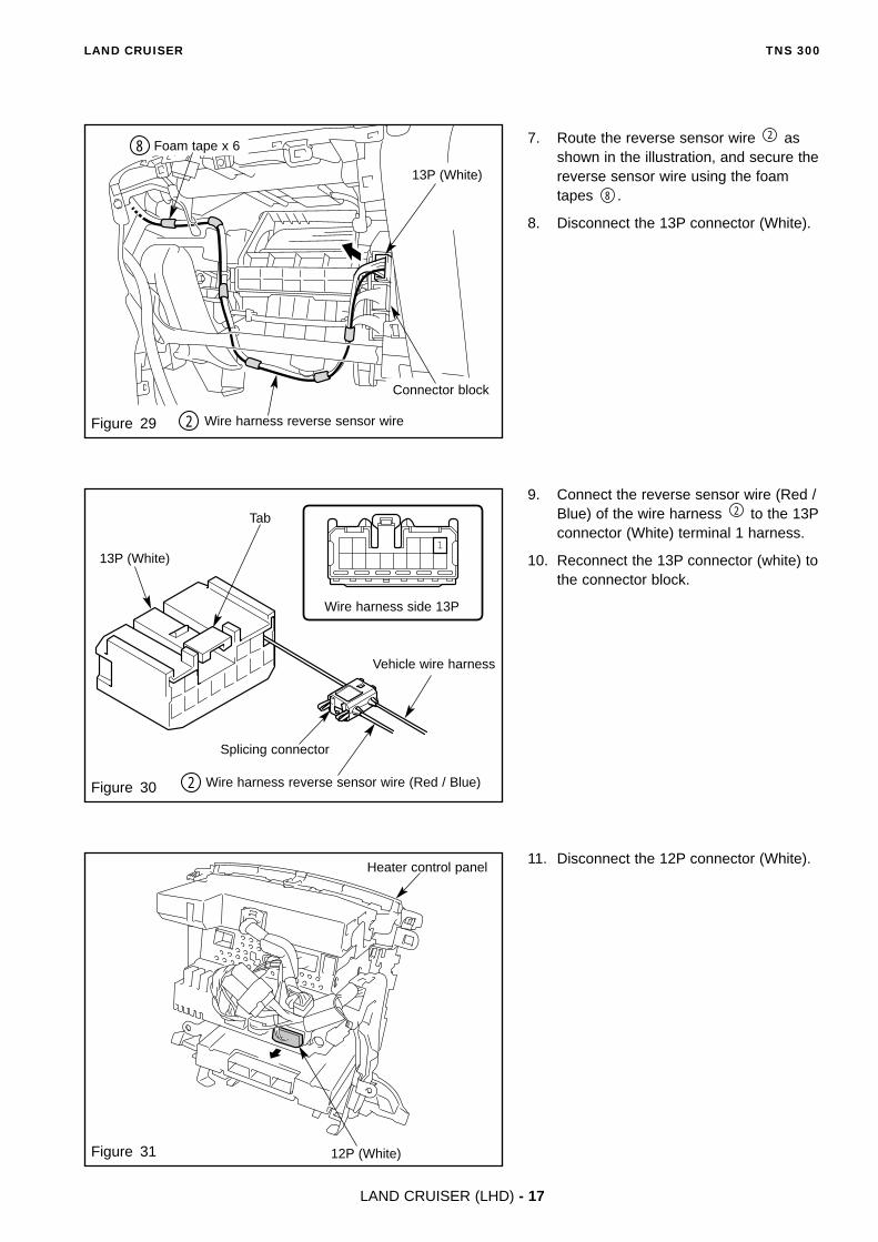
Figure 29
1
Figure 30
Figure 31
9. Connect the reverse sensor wire (Red /Blue) of the wire harness to the 13Pconnector (White) terminal 1 harness.
10. Reconnect the 13P connector (white) tothe connector block.
2
7. Route the reverse sensor wire asshown in the illustration, and secure thereverse sensor wire using the foamtapes .
8. Disconnect the 13P connector (White).
8
2
11. Disconnect the 12P connector (White).
Wire harness reverse sensor wire (Red / Blue)2
Vehicle wire harness
Splicing connector
13P (White)
Tab
Wire harness side 13P
12P (White)
Wire harness reverse sensor wire2
Foam tape x 68
13P (White)
Connector block
Heater control panel
LAND CRUISER (LHD) - 18
TNS 300LAND CRUISER
10 9
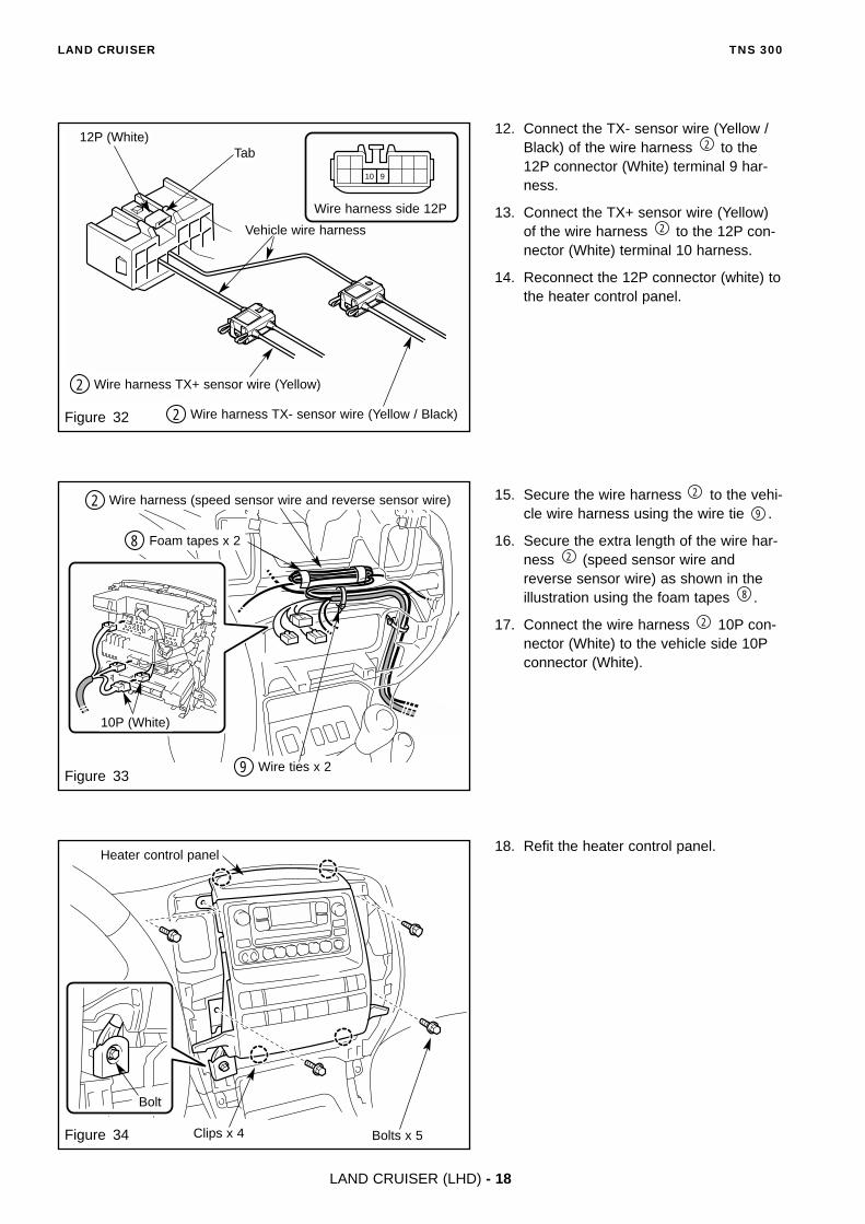
Figure 32
Figure 33
Figure 34
15. Secure the wire harness to the vehi-cle wire harness using the wire tie .
16. Secure the extra length of the wire har-ness (speed sensor wire andreverse sensor wire) as shown in theillustration using the foam tapes .
17. Connect the wire harness 10P con-nector (White) to the vehicle side 10Pconnector (White).
2
8
2
9
2
12. Connect the TX- sensor wire (Yellow /Black) of the wire harness to the12P connector (White) terminal 9 har-ness.
13. Connect the TX+ sensor wire (Yellow)of the wire harness to the 12P con-nector (White) terminal 10 harness.
14. Reconnect the 12P connector (white) tothe heater control panel.
2
2
18. Refit the heater control panel.
Clips x 4
Heater control panel
Bolts x 5
Wire harness TX- sensor wire (Yellow / Black)2
Wire harness TX+ sensor wire (Yellow)2
12P (White)Tab
Vehicle wire harness
Wire harness side 12P
10P (White)
Wire harness (speed sensor wire and reverse sensor wire)2
Foam tapes x 28
Wire ties x 29
Bolt

LAND CRUISER (LHD) - 19
TNS 300LAND CRUISER
�����������������������������
����
Figure 35
19. Route the wire harness and anten-na cord to the computer installa-tion area and attach them with foamtapes .
20. Secure the extra length of the wire har-ness and antenna cord asshown in the illustration using the foamtapes .8
32
8
13
2Foam tapes x 78
Wire harness2
Antenna cord3

LAND CRUISER (LHD) - 20
TNS 300LAND CRUISER
Figure 37
Figure 36
COMPUTER INSTALLATION
1. Fit the computer brackets to thecomputer using the bolts .
2. Attach the rest of the adhesive tapesused to fix install the plate, to the
bottom of the computer bracket asshown.
3. Attach the foam tape to the comput-er as shown in the illustration.
CAUTION : Do not remove therelease paper on the under side ofthe adhesive tapes yet.11
1
8
5
11
61
5Bracket installing position
Bolts x 46
Computer brackets x 25
Computer1
Front
115mm
50m
m
4. Cut the floor carpet in the computer installation area as shown in the illus-tration.
1
Computer1
260mm
Computer installation area
Foam tapes x 38
Vehicle Slit
Adhesive tape 11 A
Adhesive tapes x 311
Center

LAND CRUISER (LHD) - 21
TNS 300LAND CRUISER
Figure 38
6. Connect 1P connector (GPS antenna), 8P connector and 13P connector
(wire harness ) to the computer .12
3
Vehicle wire harness
5. Route the Vehicle wire harness.
Figure 39
13P
Computer1
8P 1P
Vehicle slit
Vehicle slit

Figure 40
LAND CRUISER (LHD) - 22
TNS 300LAND CRUISER
CAUTION : Put the computer ,after adjusting it in a horizontal posi-tion.
7. Install the computer on the prede-termined position.
CAUTION : When affixing the com-
puter , make sure to carefullywipe off any dirt, moisture or oilfrom the surface of the locationwhere it is to be affixed.
1
1
1
Computer1
Computer1
LAND CRUISER (LHD) - 23
TNS 300LAND CRUISER
SYSTEM START UP
POST-INSTALLATION INSPECTION
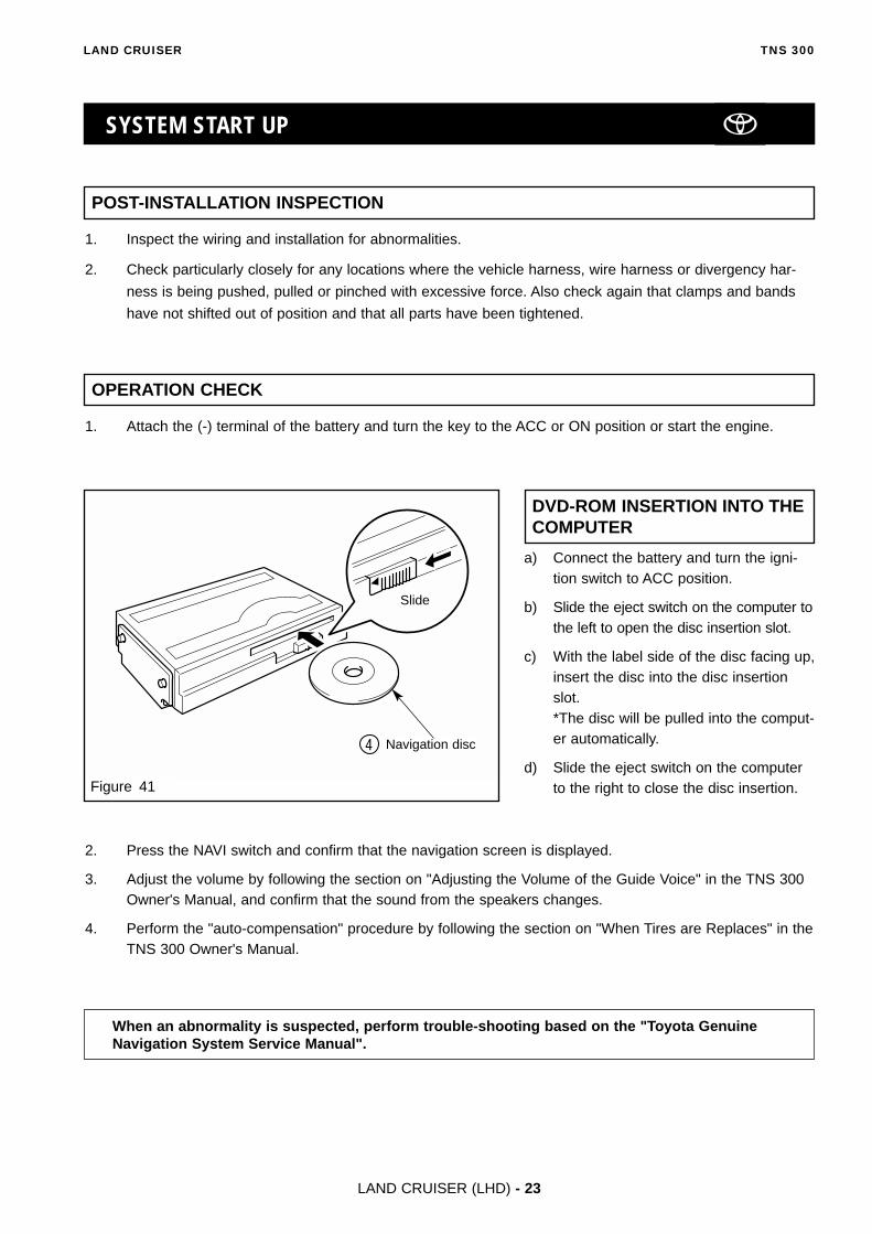
DVD-ROM INSERTION INTO THECOMPUTER
OPERATION CHECK
a) Connect the battery and turn the igni-tion switch to ACC position.
b) Slide the eject switch on the computer tothe left to open the disc insertion slot.
c) With the label side of the disc facing up,insert the disc into the disc insertionslot.*The disc will be pulled into the comput-er automatically.
d) Slide the eject switch on the computerto the right to close the disc insertion.
1. Inspect the wiring and installation for abnormalities.
2. Check particularly closely for any locations where the vehicle harness, wire harness or divergency har-
ness is being pushed, pulled or pinched with excessive force. Also check again that clamps and bands
have not shifted out of position and that all parts have been tightened.
1. Attach the (-) terminal of the battery and turn the key to the ACC or ON position or start the engine.
2. Press the NAVI switch and confirm that the navigation screen is displayed.
3. Adjust the volume by following the section on "Adjusting the Volume of the Guide Voice" in the TNS 300Owner's Manual, and confirm that the sound from the speakers changes.
4. Perform the "auto-compensation" procedure by following the section on "When Tires are Replaces" in theTNS 300 Owner's Manual.
Figure 41
Slide
Navigation disc4
When an abnormality is suspected, perform trouble-shooting based on the "Toyota GenuineNavigation System Service Manual".

LAND CRUISER (LHD) - 24
TNS 300LAND CRUISER
RESTORATION WORK
Return all vehicle parts that have been removed to their original locations. Especially make sure to attach trim
and other interior materials properly so that they do not have a detrimental effect on the function of the vehicle.
During restoration, make sure that wires are not pinched and all bolts and screws are tightened.
FINAL CHECK
1. Check that there are no locations where harnesses are pinched or abnormalities in attachment of vehicle
parts.
2. Check that there are no abnormalities in vehicle functions, including light switches, front wiper and wash-
er switches, meters, indicator lamps and warning lamps.
FINAL CHECK
