lbnco pty ltd - frasers property australia · fibre wall outlet (fwo) fibre wall outlet -...
TRANSCRIPT
LBNCo Pty Ltd Detailed Specifications, Requirements and Guidelines for
Builders and Cabling Providers
Last Updated: 30/09/2015
Issue 1

ph. 1300 667 863
2
p. 1300 667 863 e. [email protected] w. www.lbnco.com.au
Document Control © Copyright LBNCo Pty Ltd. All rights reserved. This document contains information proprietary to LBNCo Pty Ltd. Except for the purposes of evaluation; this document may not be reproduced, in whole or in part, in any form, or distributed to any party outside of LBNCo Pty Ltd, by any means, without permission in writing, from LBNCo Pty Ltd.
This document is classified to the level indicated at the top of this page. Any classification containing the word confidence or confidential means the document is to be placed out of sight when not in use and placed in a drawer or cupboard when the room will be unattended. Any classification containing the word secret means the document is always to be in someone’s hand or under secure lock when not in use.
Issue #
Issue Date Revision Revision Date
Comments Prepared By Authorised By
1 30/09/15 0 Document created for builders and owners
Tim O’Dea Ben Seaman
Distribution List
Document Approval
Name Association Signature Date Tim O’Dea Document creator Lachlan Delaney Field Support Manager Terry Limnidis Connections Manager Ben Seaman Chief Technical Officer Stephen Picton Chief Executive Officer

ph. 1300 667 863
3
p. 1300 667 863 e. [email protected] w. www.lbnco.com.au
PURPOSE
The purpose of this document is to provide detailed technical guidance and information to developers, builders, electrical contractors, telecommunications cabling providers ‘cablers’ and end-users about connection of premises to the LBNCo Fibre to the Premises (FttP) network.
This document is referenced by other summary documents which are specifically aimed at Builders and Premises (Home) Owners.
SCOPE Applies to connecting any building constructed for use as a dwelling or small business within greenfields broadacre real estate developments where LBNCo has been selected as the FttP provider.
It applies to detached buildings (single dwellings) and semi-detached buildings such as town houses, duplexes, triplexes etc.
It also applies to group and strata housing on ‘Super Lots’ although special arrangements would have to be made to accommodate these.
It is specifically for the end-user end of the network from the LBNCo Service Drop Pit in the street reserve and for FttP connections where the Network Termination Device (NTD) is installed internally within the premises.
GLOSSARY and DEFINITIONS Builder Contracted by the Owner to build the premises. Developer The seller of the Lot of land. Builds and provides
infrastructure in the estate. Finished Ground Level (FGL) This is the level of the ground external to the home after the
Lot is Levelled Fibre-to-the-Premises (FttP) Telecommunication Network using an optical fibre to each of
the premises Fibre Wall Outlet (FWO) Fibre Wall Outlet - termination point of the fibre from PCD to
NTD General Power Outlet (GPO) General Power Outlet - switched electrical power socket used
in premises Electricity Connection Pillar Owned by the electricity supplier and connects the
underground electricity network to the premises. In the form of an above ground green dome or box.
Home Distributor (HD) Equipment from which telecommunications and TV cabling is distributed to outlets throughout the premises. Is usually housed within and enclosure or cabinet and can also be described as a Smart Wiring Hub or Distribution Hub. Can also house LBNCo’s NTD equipment.
Internal Conduit Conduit inside the premises that carriers the optic fibre cable from the PCD to the NTD
LBNCo Licenced carrier building and operating the FttP network. Wholesale Service Provider.

ph. 1300 667 863
4
p. 1300 667 863 e. [email protected] w. www.lbnco.com.au
Lot The parcel of land purchased by the landowner from the Developer. Sometimes known as the house lot or block.
Network Termination Device (NTD) The device where the optical fibre terminates at the premises and converts electronic signals to and from light signals. It provides the interface with customer wiring.
Occupant The occupier of the premises once built. Can be the Owner or Tennant
Optical Network Unit (ONU) LBNCo term for the NTD, also known as ONT Optical Network Transceiver
Owner The purchaser of the Lot of land and owner of premises to be built
Premises Termination Device (PCD)
The device where the lead-in fibre terminates and is connected to the Internal Fibre between the PCD and the NTD. Can be referred to as the Utility Box.
Pit Plastic communications enclosure part buried in the ground that contains the network distribution equipment
Uninterruptable Power Supply (UPS)
Battery back-up power supply
Utility Box Another description of the PCD Radio Frequency (RF) Radio Frequency signal Retail Service Provider (RSP) Retail Service Provider - provides the services to the end-
user Service Drop 'Lead-in' - The connection from the Pit to the PCD Service Drop Conduit The conduit from the Pit to the PCD that carries the Optical
Fibre lead-in fibre cable Starter Conduit Conduit from the Pit that is joined to the Service Drop Conduit
and carries the lead-in fibre User Network Interface Data (UNI-D)
User Network Interface – Data (RJ45 Ethernet data port)
User Network Interface Voice (UNI-V)
User Network Interface – Voice (RJ11 telephone port)

ph. 1300 667 863
5
p. 1300 667 863 e. [email protected] w. www.lbnco.com.au
RESPONSIBILITIES The following table shows who is responsible for what components in the installation and connection process. Developer Ensures that the land purchaser and potential building owner are aware of
the requirements for the premises to be connected to the LBNCo FttP network as laid out in this document including the consequences of not complying.
Provides the land purchaser with access to documents or websites laying out the requirements during the planning, design and building stages, including this document.
Note: The land purchaser can be an owner who engages a builder to plan and construct the premises or could be a developer/ builder who offers the land as part of a house and land package.
Land Purchaser /Premises Owner
Ensures that the Builder has access to this and other relevant documents prior to finalising plans for the building.
Discusses the requirements and reaches agreement with the builder about: Telecommunications services required and where Entertainment services required and where (Free-to-air TV, pay TV,
Subscription TV etc) Location and placement of the LBNCo fibre equipment Internal customer cabling Compliance with these guidelines
o Space and pathway requirements o Equipment specifications (conduits etc)
Note: Where the premises are to be rented/leased after completion, the
premises owner ensures that the premises are suitably prepared during the building stage prior to tenanting to allow for LBNCo equipment to be installed when the tenant applies for services from a Retail Service Provider. In particular pre-installation of Service Drop and Internal Conduits, allocation of space for the Premises Connection Device (PCD) and NTD and provision of a General Power Outlet (GPO) at the NTD location is essential.

ph. 1300 667 863
6
p. 1300 667 863 e. [email protected] w. www.lbnco.com.au
Builder (including sub-contractors such as electricians and cabling providers)
Installs the facilities required to connect the LBNCo fibre network to the premises including:
Service Drop (Lead-in) Conduit with draw rope Internal conduit from the PCD location to the NTD location with draw
rope GPO at the NTD location
Internal customer cabling and outlets to the Building owners requirements including for:
Telephone Data Security Home care and safety Entertainment Home automation Routing, patching and splitting Power circuits
Installs the Home Distributor (HD) as required by the Owner Connects internal cabling to the Network Boundary at the NTD LBNCo Provides and operates the FttP infrastructure to which the premises are to
be connected to enable provision of services by the Retail Service Provider (RSP)
Provides the Street Pit and Starter Conduit Supply and install
PCD (Utility box) NTD including
o NTD device (ONU) o Fibre Wall Outlet (FWO) o Power supply
Service Drop ‘Lead-in’ fibre optic cable Internal ‘PCD to NTD’ fibre optic cable
Occupant (including tenants)
Contacts and applies to the RSP of their choice for provision of services
Retail Service Provider (RSP)
Provides Services via the Network Boundary Ports at the NTD including: Superfast Broadband Telephone Entertainment
Initiates the installation and activation of the LBNCo equipment at the premises

ph. 1300 667 863
7
p. 1300 667 863 e. [email protected] w. www.lbnco.com.au
IMPORTANT INFORMATION – READ BEFORE YOU START Network Boundary Point The network boundary in the LBNCo FttP network is at the Service Ports of the NTD as shown here:
ACMA Wiring Rules All cabling work performed on the customer side of the Network Boundary Point is subject to the Australian Communications and Media Authority (ACMA) administered Telecommunications Cabling Provider Rules 2014 (CPRs) and must be cabled according to the standard AS CA S009-2013 Installation requirements for customer cabling (Wiring Rules).
Cabling work includes the connection, installation or maintenance (repair) of Customer cabling.
Cabling work must be carried out by installers registered to install customer premises cabling.
Cabling on the LBNCo side of the Network Boundary, up to and including the Network Boundary, is not covered by these ACMA rules.

ph. 1300 667 863
8
p. 1300 667 863 e. [email protected] w. www.lbnco.com.au
Building Project Timeline The following is provided to assist with determining who needs to do what and when, and what to expect during the lifecycle of the building project with reference to the LBNCo installation and connection. There will be variations with different types of developments, buildings, customers, builders, connections and RSPs, however this is typical of a home building project in a greenfields broadacre development. Project Stage What Who Prior to building commencement
FttP network installed Pipe and pit installed Service Drop Starter Conduit
installed FttP fibre network installed and
commissioned
LBNCo
Prior to building commencement (pre-start)
Plan and design telecommunications and entertainment requirements for the building including:
Location of PCD Location of NTD Internal cabling
Owner and Builder
From building commencement and prior to driveways and landscaping – at the same time as the power lead-in conduit is installed
Install Service Drop Conduit including connection to the Starter Conduit and installing the Draw Rope
Builder
Before plate height (before roof completed) when electrical conduits and wiring is installed
Install Internal Conduit including Draw Rope
Builder
Provide for installation of GPO at NTD location
Builder
After lock-up (final fit-off) Install GPO faceplate at NTD location Builder Prior to handover Contact RSP of choice and apply for
services Owner
At completion of building can be prior to or after handover (requires power connection)
Install and commission LBNCo equipment
LBNCo (initiated by the RSP)
After installation of LBNCo equipment
Connect Customer Cabling to LBNCo NTD at the Network Boundary
RSP, Builder, Owner
Activate services RSP and Owner

ph. 1300 667 863
9
p. 1300 667 863 e. [email protected] w. www.lbnco.com.au
OVERALL DESCRIPTION AND SPECIFICATIONS Overall System Diagram
ph. 1300 667 863
10
p. 1300 667 863 e. [email protected] w. www.lbnco.com.au
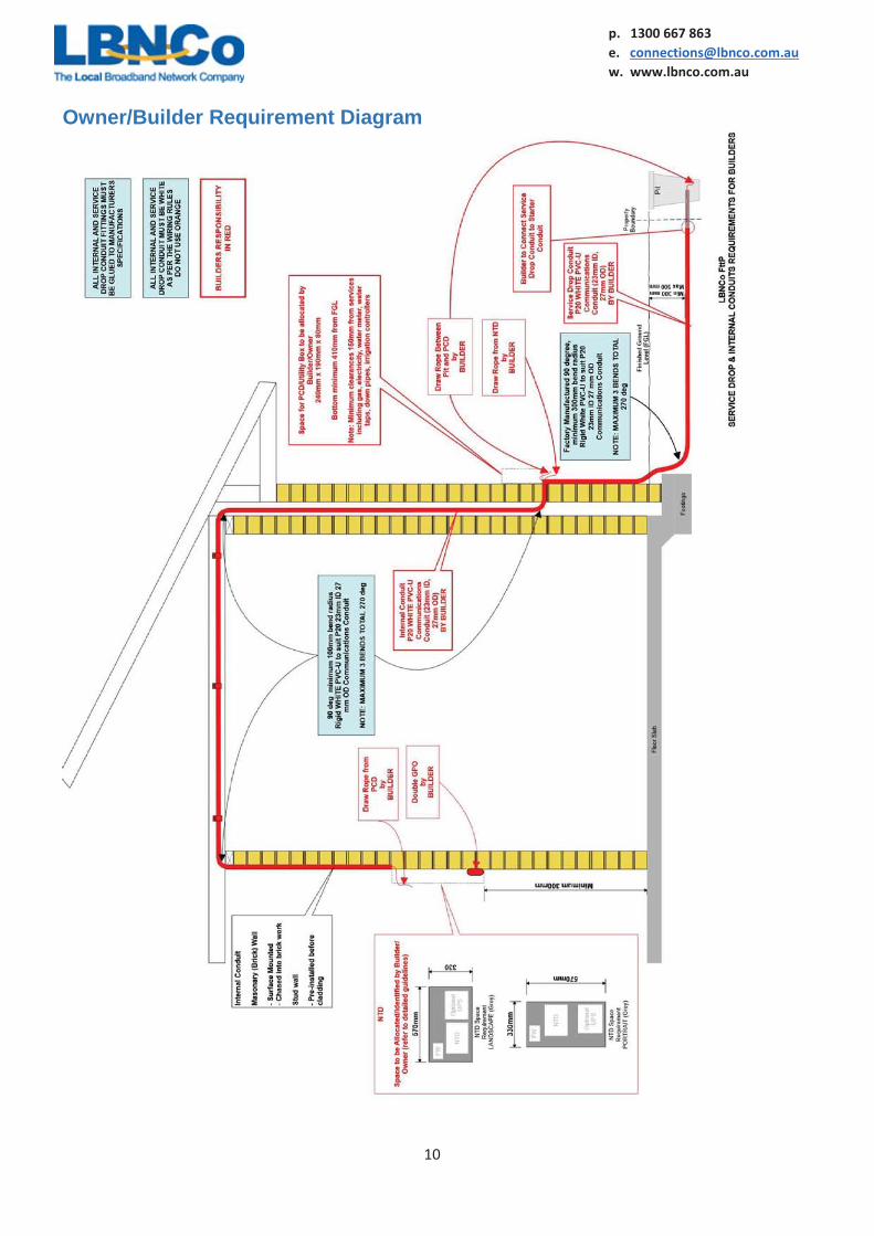
Owner/Builder Requirement Diagram

ph. 1300 667 863
11
p. 1300 667 863 e. [email protected] w. www.lbnco.com.au
System Components PIT Provided and installed by LBNCo Located, usually for a standard front loaded Lot, in the street verge near to the front boundary at the
junction with one of the side boundaries of the Lot.
The following is a table showing the Pit types used by LBNCo and the most common location for those pits and Starter Conduits in relation to the Lot boundaries. This is to assist builders in locating the Starter Conduit.
Type Image/Drawing P2
ph. 1300 667 863
12
p. 1300 667 863 e. [email protected] w. www.lbnco.com.au
P5
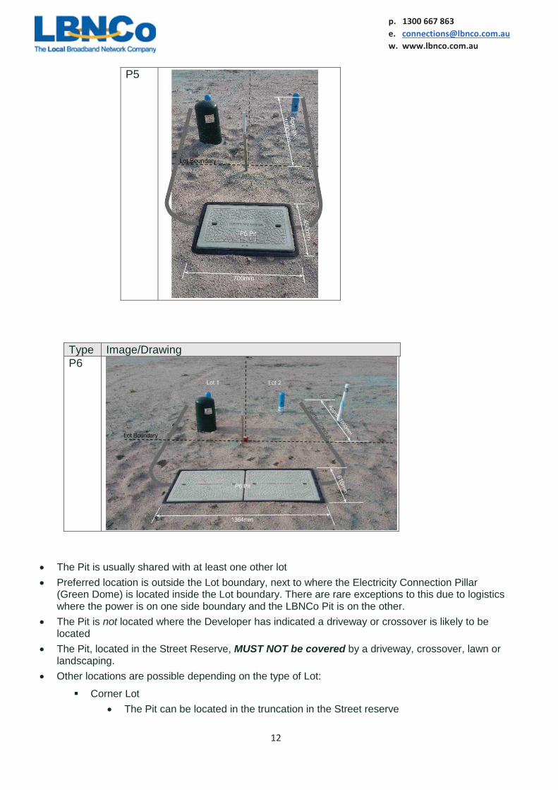
Type Image/Drawing P6
The Pit is usually shared with at least one other lot Preferred location is outside the Lot boundary, next to where the Electricity Connection Pillar
(Green Dome) is located inside the Lot boundary. There are rare exceptions to this due to logistics where the power is on one side boundary and the LBNCo Pit is on the other.
The Pit is not located where the Developer has indicated a driveway or crossover is likely to be located
The Pit, located in the Street Reserve, MUST NOT be covered by a driveway, crossover, lawn or landscaping.
Other locations are possible depending on the type of Lot:
Corner Lot The Pit can be located in the truncation in the Street reserve

ph. 1300 667 863
13
p. 1300 667 863 e. [email protected] w. www.lbnco.com.au
The Pit can be located at the rear of the Lot because that boundary is on the narrow side of the Lot
Front loaded Lot Retaining Wall – the pit will be located in the street reserve on the junction of the
Front Boundary (which is usually the front surface of the wall) and a side boundary. Refer to the Starter Conduit Special Case – Retaining Wall below.
Rear Loaded Lot (Rear Laneway)
Power and Communications provided from a Laneway at the rear of the Lot Not usually located in the roadway An easement is usually provided by the Developer on a common boundary with
another Lot (this is NOT the Power Exclusion Zone for the Electricity Power Pillar (Green Dome))
The future location of garages, carports and associated driveways and crossovers are taken into account by the Developer in siting these pits and other utilities
STARTER CONDUIT Provided by LBNCo Connected to the Pit The building end is located approximately 1,000mm (1metre) inside the front boundary between
300mm and 500mm below the FGL (see the pictures in the table above) Special case – Retaining Wall
The Pit is in the street reserve. The Starter Conduit passes under the Retaining Wall in a 50mm sleeve conduit to protect it
against crushing. The Stater Conduit rises vertically within the Lot and is swept back toward the Retaining
Wall so that its end is as close to the wall as possible.
ph. 1300 667 863
14
p. 1300 667 863 e. [email protected] w. www.lbnco.com.au
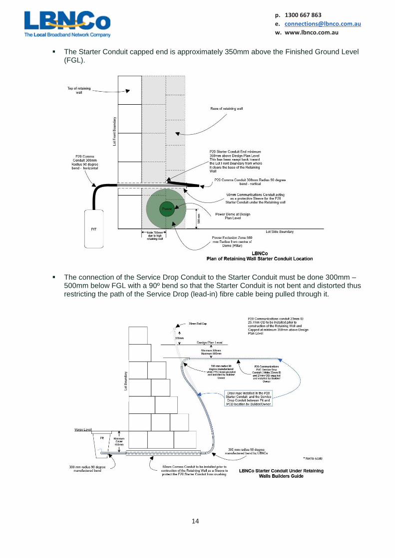
The Starter Conduit capped end is approximately 350mm above the Finished Ground Level (FGL).
The connection of the Service Drop Conduit to the Starter Conduit must be done 300mm –
500mm below FGL with a 90º bend so that the Starter Conduit is not bent and distorted thus restricting the path of the Service Drop (lead-in) fibre cable being pulled through it.
ph. 1300 667 863
15
p. 1300 667 863 e. [email protected] w. www.lbnco.com.au
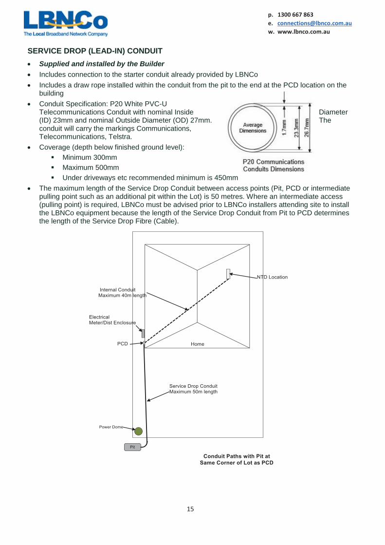
SERVICE DROP (LEAD-IN) CONDUIT Supplied and installed by the Builder Includes connection to the starter conduit already provided by LBNCo Includes a draw rope installed within the conduit from the pit to the end at the PCD location on the
building Conduit Specification: P20 White PVC-U
Telecommunications Conduit with nominal Inside Diameter (ID) 23mm and nominal Outside Diameter (OD) 27mm. The conduit will carry the markings Communications, Telecommunications, Telstra.
Coverage (depth below finished ground level): Minimum 300mm Maximum 500mm Under driveways etc recommended minimum is 450mm
The maximum length of the Service Drop Conduit between access points (Pit, PCD or intermediate pulling point such as an additional pit within the Lot) is 50 metres. Where an intermediate access (pulling point) is required, LBNCo must be advised prior to LBNCo installers attending site to install the LBNCo equipment because the length of the Service Drop Conduit from Pit to PCD determines the length of the Service Drop Fibre (Cable).

ph. 1300 667 863
16
p. 1300 667 863 e. [email protected] w. www.lbnco.com.au
Where practical it is recommended that a trench be shared with the electrical power lead-in cabling/conduit because, normally, both go to common locations at either end (the PCD should be located near the power meter/distribution box).
Communications conduit should be at a higher level in the trench than power: Power minimum cover is 500mm Communications minimum cover is 300mm
Because the communications conduit carries no metallic cables there is no strict requirement for separation from the power conduit
All bends and fittings will suit this conduit and will be rigid. Flexible or corrugated conduit, fittings and bends are not acceptable. These must be factory fabricated.
All joints will be glued to the manufacturer’s specification for water proofing and to prevent the conduit and fittings from separating due to external pressure or during the pulling of cable through the conduit
Bends: All bends must be factory fabricated. The use of bends manufactured from conduit using heat is not accepted because distortion
of the conduit will impede pulling of the connectorised service drop fibre through it. Tight bending of conduit which results in distortion of the conduit is also not acceptable. The inside bend angle is to be minimum 90º.
Minimum Bend Radius 300mm (note: pre-fabricated bends are usually specified at 305mm
bend radius)
ph. 1300 667 863
17
p. 1300 667 863 e. [email protected] w. www.lbnco.com.au
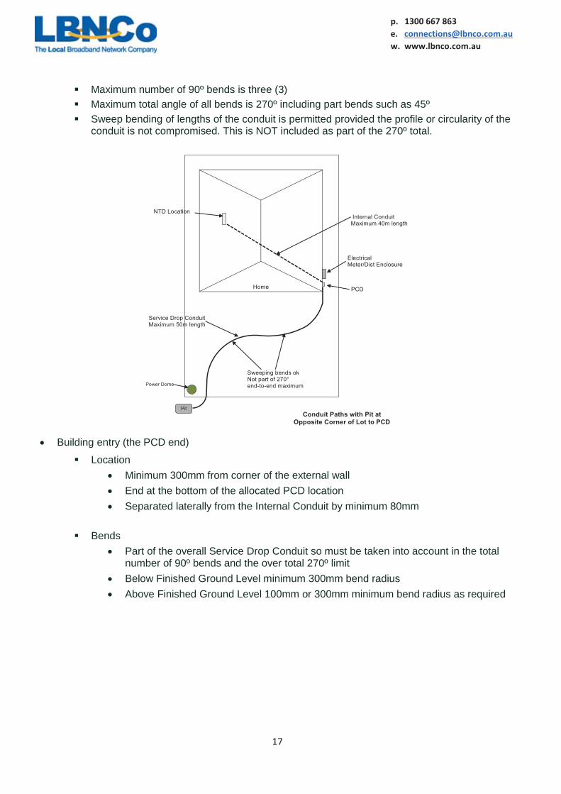
Maximum number of 90º bends is three (3) Maximum total angle of all bends is 270º including part bends such as 45º Sweep bending of lengths of the conduit is permitted provided the profile or circularity of the
conduit is not compromised. This is NOT included as part of the 270º total.
Building entry (the PCD end)
Location Minimum 300mm from corner of the external wall End at the bottom of the allocated PCD location Separated laterally from the Internal Conduit by minimum 80mm
Bends
Part of the overall Service Drop Conduit so must be taken into account in the total number of 90º bends and the over total 270º limit
Below Finished Ground Level minimum 300mm bend radius Above Finished Ground Level 100mm or 300mm minimum bend radius as required


ph. 1300 667 863
19
p. 1300 667 863 e. [email protected] w. www.lbnco.com.au
PREMISES CONNECTION DEVICE (PCD) Location
Allocated by the Builder/Owner based on the following requirements: Near to the Electrical Meter/Distribution Enclosure Footprint - the space required for the equipment is:
W 190mm x H 240mm x D 80mm plus clearances (see exclusion zone below)
The height from Finished Ground Level to bottom side of PCD equipment is minimum 410mm to maximum 1500mm.
ph. 1300 667 863
20
p. 1300 667 863 e. [email protected] w. www.lbnco.com.au
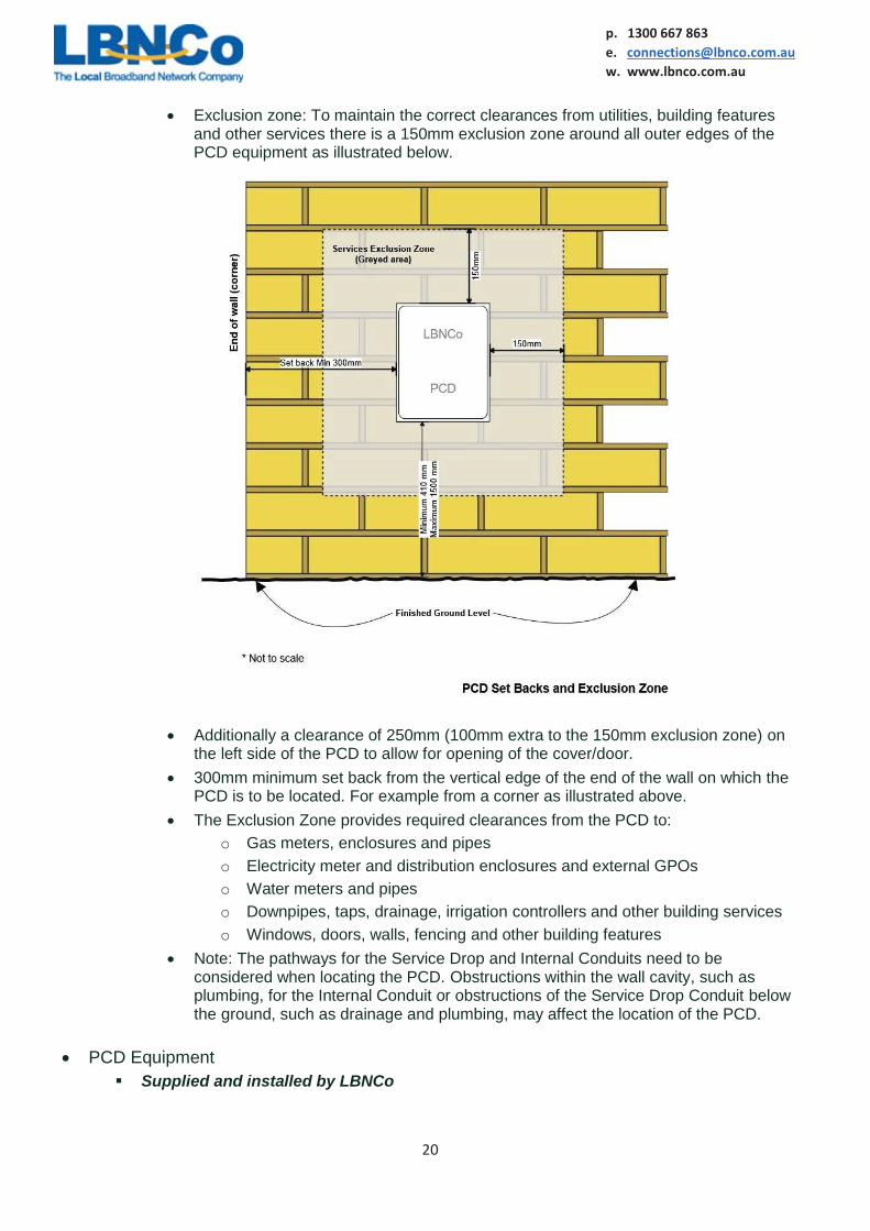
Exclusion zone: To maintain the correct clearances from utilities, building features and other services there is a 150mm exclusion zone around all outer edges of the PCD equipment as illustrated below.
Additionally a clearance of 250mm (100mm extra to the 150mm exclusion zone) on
the left side of the PCD to allow for opening of the cover/door. 300mm minimum set back from the vertical edge of the end of the wall on which the
PCD is to be located. For example from a corner as illustrated above. The Exclusion Zone provides required clearances from the PCD to:
o Gas meters, enclosures and pipes o Electricity meter and distribution enclosures and external GPOs o Water meters and pipes o Downpipes, taps, drainage, irrigation controllers and other building services o Windows, doors, walls, fencing and other building features
Note: The pathways for the Service Drop and Internal Conduits need to be considered when locating the PCD. Obstructions within the wall cavity, such as plumbing, for the Internal Conduit or obstructions of the Service Drop Conduit below the ground, such as drainage and plumbing, may affect the location of the PCD.
PCD Equipment Supplied and installed by LBNCo

ph. 1300 667 863
21
p. 1300 667 863 e. [email protected] w. www.lbnco.com.au
INTERNAL CONDUIT Supplied and installed by Builder The Internal Conduit will be installed according to the requirements and specifications of the AS/CA
S009:2013 Installation requirements for customer cabling (Wiring rules) for internal telecommunications conduits and fittings
The Internal Conduit includes a draw rope installed within the conduit from the PCD to the end at the NTD location within the building
Conduit Specification: P20 White PVC-U Telecommunications Conduit with nominal Inside Diameter (ID) 23mm and nominal Outside Diameter (OD) 27mm. The conduit will carry the markings Communications, Telecommunications, Telstra.
All bends and fittings will suit this conduit and will be rigid. Flexible or corrugated conduit, fittings and bends are not acceptable. Must be factory fabricated.
All joints will be glued to the manufacturer’s specification for water proofing and to prevent the conduit and fittings from separating due to external pressure or during the pulling of cable through the conduit.
Bends: All bends must be factory fabricated. The use of bends manufactured from conduit using heat is not accepted because distortion
of the conduit will impede pulling of the connectorised optic fibre lead between the PCD and NTD.
Tight bending of conduit which results in distortion of the conduit is also not acceptable. The inside bend angle to be minimum 90º.

ph. 1300 667 863
22
p. 1300 667 863 e. [email protected] w. www.lbnco.com.au
Minimum Bend Radius 100mm (note: pre-fabricated bends are usually specified at 105mm bend radius)
Maximum number of 90º bends in the end-to-end Internal Conduit is three (3) Maximum total of all bends is 270º including part bends such as 45º Sweep bending of lengths of the conduit is permitted provided the profile or circularity of the
conduit is not compromised. This is NOT included as part of the 270º total.
NETWORK TERMINATION DEVICE (NTD) The location of the NTD and associated equipment needs to be included as part of the planning
and design for the premises by the Owner and Builder based on the following requirements and parameters.
Overall telecommunications and electronic entertainment requirements need to be considered during this planning and design process. The complexity relates more to the internal cabling of the premises which connects to the LBNCo equipment. This has a bearing on the location and housing of the LBNCo equipment. For instance an HD enclosure may be required to house the customer distribution equipment and this can also house the LBNCo NTD equipment. The following are the minimum requirements and specifications for the installation of LBNCo NTD equipment that form the pre-requisite for connection to the LBNCo FttP Network:
ph. 1300 667 863
23
p. 1300 667 863 e. [email protected] w. www.lbnco.com.au
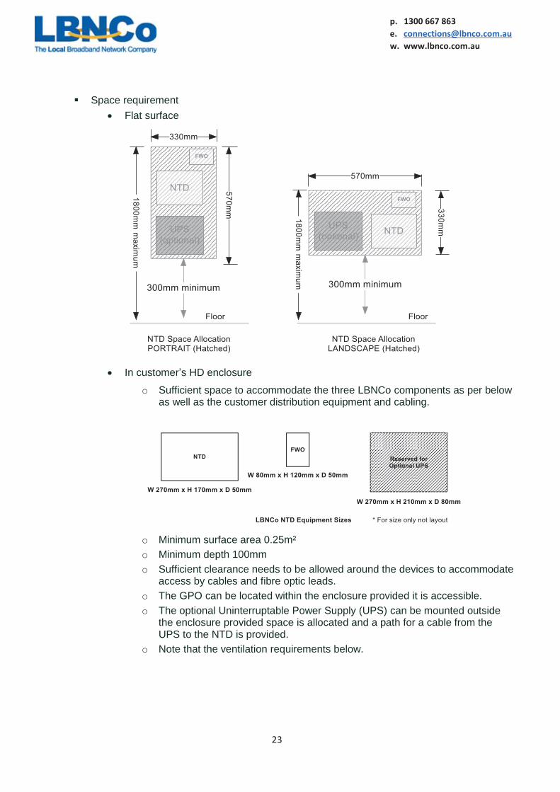
Space requirement Flat surface
In customer’s HD enclosure
o Sufficient space to accommodate the three LBNCo components as per below as well as the customer distribution equipment and cabling.
o Minimum surface area 0.25m² o Minimum depth 100mm o Sufficient clearance needs to be allowed around the devices to accommodate
access by cables and fibre optic leads. o The GPO can be located within the enclosure provided it is accessible. o The optional Uninterruptable Power Supply (UPS) can be mounted outside
the enclosure provided space is allocated and a path for a cable from the UPS to the NTD is provided.
o Note that the ventilation requirements below.

ph. 1300 667 863
24
p. 1300 667 863 e. [email protected] w. www.lbnco.com.au
Location
General requirements
o Ventilation; the equipment generates heat and the space surrounding the equipment must be sufficient to allow for air circulation through the equipment’s vents and for the heated air to dissipate.
Open wall mounted equipment in a room or garage with no obstructions, 200mm clearance to all equipment surfaces, near the equipment; the volume of the space should be sufficient.
Open wall mounted within a cupboard, storeroom or wardrobe with no obstructions near the equipment (refer to “clearance” below) the volume of the space should be greater than 1.0 m³ (1,000 lt) or the space must be ventilated.
Mounted within an HD enclosure The enclosure must have built in ventilation openings (vents)
that allow circulation of air through the equipment There must be sufficient space surrounding the enclosure to
dissipate the heated air from the enclosure o Such an enclosure can be used within a large room or
garage o Where mounted within a cupboard, storeroom or
wardrobe the volume of the space must be greater than 1.0 m³ (1,000 lt)
o Ambient temperature; the equipment must not be exposed to consistent ambient temperatures above 40º Celsius or below 0º Celsius.
o Exposure; the location must be fully enclosed (internal to the building) and must not be on the outside of external walls of the building.
o Safety; the location must not present potential trip, choking, electrical shock, exposure to laser light or physical injury hazards from the equipment, including cables, when installed.
o Clearance; there must be no objects which will come into direct contact with, block ventilation for or prevent access to the equipment installed; minimum 200mm clearance to all equipment surfaces (top, bottom, sides and front).
o Appliances and plant; the NTD equipment MUST NOT be mounted near to or within the same space as gas appliances, hot water systems, SPA’s or pools.
Permitted locations o Enclosed garage under the main roof (LBNCo preferred location). o Storage room or cupboard of sufficient volume to accommodate the
ventilation requirements and meets the clearance requirements. o Walk-in wardrobe of sufficient volume to accommodate the ventilation
requirements and meets the clearance requirements. o Office or study. o Living room provided it meets safety requirements (should not be accessible
by children). o Theatre/multimedia room.
ph. 1300 667 863
25
p. 1300 667 863 e. [email protected] w. www.lbnco.com.au
Locations Not permitted for safety and environmental reasons:
o Wet areas Bathroom Toilet Laundry Kitchen
o Safety hazards Children’s bedroom Play area Anywhere cables could present a choke or trip hazard
o Exposure Under a window that opens to the outside Carport Patio Veranda Balcony Anywhere not fully enclosed and internal to the building
o Other technical Standalone sheds Standalone garage (not under main roof) Coolroom, freezer Sauna
NTD Equipment Components
All of the components listed below must be located together within one meter and within the same room or space:
GPO Supplied and installed by Builder Recommended double GPO to allow for requirements for customer equipment
FWO Supplied and installed by LBNCo
NTD Supplied and installed by LBNCo
Power Supply Standard
o Supplied and installed by LBNCo UPS (Battery backup) – Optional
o Supplied and installed by LBNCo Customer Cabling – to connect into the LBNCo equipment at the Network Boundary