lbi-38986 - edacs conventional network interface getc
TRANSCRIPT

EDACS®
CONVENTIONAL NETWORK INTERFACE (CNI)GETC CONFIGURATION MANUAL
TABLE OF CONTENTSSPECIFICATIONS* . . . . . . . . . . . . . . . . . . . . . . . . . . . . . . . . . . . . . . . . . . . . . . . . . . 3
SCOPE . . . . . . . . . . . . . . . . . . . . . . . . . . . . . . . . . . . . . . . . . . . . . . . . . . . . . . . . . 3
INTRODUCTION . . . . . . . . . . . . . . . . . . . . . . . . . . . . . . . . . . . . . . . . . . . . . . . . . . . 3
SOFTWARE REQUIREMENTS . . . . . . . . . . . . . . . . . . . . . . . . . . . . . . . . . . . . . . . . . . . 4
RELATED PUBLICATIONS . . . . . . . . . . . . . . . . . . . . . . . . . . . . . . . . . . . . . . . . . . . . . 5
OPERATION . . . . . . . . . . . . . . . . . . . . . . . . . . . . . . . . . . . . . . . . . . . . . . . . . . . . . 5
GENERAL . . . . . . . . . . . . . . . . . . . . . . . . . . . . . . . . . . . . . . . . . . . . . . . . . . . . 5
INTERFACE TO EDACS . . . . . . . . . . . . . . . . . . . . . . . . . . . . . . . . . . . . . . . . . . . . 5
CONSOLE PREEMPT . . . . . . . . . . . . . . . . . . . . . . . . . . . . . . . . . . . . . . . . . . . . . 6
CHANNEL GUARD MAPPING . . . . . . . . . . . . . . . . . . . . . . . . . . . . . . . . . . . . . . . . 6
MAPPING WITHOUT CHANNEL GUARD . . . . . . . . . . . . . . . . . . . . . . . . . . . . . . . . . 6
INSTALLATION . . . . . . . . . . . . . . . . . . . . . . . . . . . . . . . . . . . . . . . . . . . . . . . . . . . 6
EQUIPMENT REQUIRED . . . . . . . . . . . . . . . . . . . . . . . . . . . . . . . . . . . . . . . . . . . 7
HARDWARE INSTALLATION . . . . . . . . . . . . . . . . . . . . . . . . . . . . . . . . . . . . . . . . 7Logic Board Modification . . . . . . . . . . . . . . . . . . . . . . . . . . . . . . . . . . . . . . . 7Rockwell Modem Installation . . . . . . . . . . . . . . . . . . . . . . . . . . . . . . . . . . . . . 8Turbo Board Installation . . . . . . . . . . . . . . . . . . . . . . . . . . . . . . . . . . . . . . . . 9GETC Cable Modifications . . . . . . . . . . . . . . . . . . . . . . . . . . . . . . . . . . . . . . 10Jumper Installation . . . . . . . . . . . . . . . . . . . . . . . . . . . . . . . . . . . . . . . . . . . 11
GETC FIRMWARE INSTALLATION . . . . . . . . . . . . . . . . . . . . . . . . . . . . . . . . . . . . . 11EPROM Installation . . . . . . . . . . . . . . . . . . . . . . . . . . . . . . . . . . . . . . . . . . 11
TURBO SOFTWARE INSTALLATION . . . . . . . . . . . . . . . . . . . . . . . . . . . . . . . . . . . . 11Preparation . . . . . . . . . . . . . . . . . . . . . . . . . . . . . . . . . . . . . . . . . . . . . . . 12Programming Mode . . . . . . . . . . . . . . . . . . . . . . . . . . . . . . . . . . . . . . . . . . 12Normal Mode . . . . . . . . . . . . . . . . . . . . . . . . . . . . . . . . . . . . . . . . . . . . . 12
CONFIGURATION . . . . . . . . . . . . . . . . . . . . . . . . . . . . . . . . . . . . . . . . . . . . . . . . . . 15
PERSONALITY PROGRAMMING . . . . . . . . . . . . . . . . . . . . . . . . . . . . . . . . . . . . . . 15Programming Set-up . . . . . . . . . . . . . . . . . . . . . . . . . . . . . . . . . . . . . . . . . . 15Programming the Personality . . . . . . . . . . . . . . . . . . . . . . . . . . . . . . . . . . . . . 15
REPEATER PERSONALITY . . . . . . . . . . . . . . . . . . . . . . . . . . . . . . . . . . . . . . . . . . 17
DIP SWITCH SETTINGS . . . . . . . . . . . . . . . . . . . . . . . . . . . . . . . . . . . . . . . . . . . . 17
MODEM ALIGNMENT . . . . . . . . . . . . . . . . . . . . . . . . . . . . . . . . . . . . . . . . . . . . 17
CEC/IMC PERSONALITY CONFIGURATION . . . . . . . . . . . . . . . . . . . . . . . . . . . . . . . . 20
ERICSSONZ
LBI-38986
TABLE OF CONTENTS - Cont.LED INDICATORS . . . . . . . . . . . . . . . . . . . . . . . . . . . . . . . . . . . . . . . . . . . . . . . . . . 20
TEST AND ALIGNMENT . . . . . . . . . . . . . . . . . . . . . . . . . . . . . . . . . . . . . . . . . . . . . . 20
FUNCTIONAL CHECKOUT . . . . . . . . . . . . . . . . . . . . . . . . . . . . . . . . . . . . . . . . . 20Locally Initiated Call . . . . . . . . . . . . . . . . . . . . . . . . . . . . . . . . . . . . . . . . . 20Multisite Initiated Call . . . . . . . . . . . . . . . . . . . . . . . . . . . . . . . . . . . . . . . . . 21
REPEATER ADJUSTMENTS . . . . . . . . . . . . . . . . . . . . . . . . . . . . . . . . . . . . . . . . . 21MASTR II and IIe Repeaters . . . . . . . . . . . . . . . . . . . . . . . . . . . . . . . . . . . . . 21MASTR IIIRepeaters . . . . . . . . . . . . . . . . . . . . . . . . . . . . . . . . . . . . . . . . . 22
TROUBLESHOOTING . . . . . . . . . . . . . . . . . . . . . . . . . . . . . . . . . . . . . . . . . . . . . . . . 22
CNI INTERFACE REQUIREMENTS . . . . . . . . . . . . . . . . . . . . . . . . . . . . . . . . . . . . . . . . 23
INTERCONNECT DIAGRAMS . . . . . . . . . . . . . . . . . . . . . . . . . . . . . . . . . . . . . . . . . . . 27
INSTALLATION DIAGRAMS . . . . . . . . . . . . . . . . . . . . . . . . . . . . . . . . . . . . . . . . . . . . 29
FIGURES and TABLESFigure 1- CNI Block Diagram . . . . . . . . . . . . . . . . . . . . . . . . . . . . . . . . . . . . . . . . . . . . 4
Figure 2 - DataCommunication . . . . . . . . . . . . . . . . . . . . . . . . . . . . . . . . . . . . . . . . . . . . 6
Figure 3 - Logic Board (19D904266) Modification . . . . . . . . . . . . . . . . . . . . . . . . . . . . . . . . . 8
Figure 4 - Simplified Diagram of Modified Circuit . . . . . . . . . . . . . . . . . . . . . . . . . . . . . . . . . 8
Figure 5 - GETC Shelf (Rear View) . . . . . . . . . . . . . . . . . . . . . . . . . . . . . . . . . . . . . . . . . 10
Figure 6 - Simplified Diagram of Modified Harness . . . . . . . . . . . . . . . . . . . . . . . . . . . . . . . . . 11
Figure 7 - CNI GETC(19D904266) Jumper Locations . . . . . . . . . . . . . . . . . . . . . . . . . . . . . . . . 13
Figure 8 - Turbo Board Programming . . . . . . . . . . . . . . . . . . . . . . . . . . . . . . . . . . . . . . . . 13
Figure 9 - Switch Settings for Personality Programming Mode . . . . . . . . . . . . . . . . . . . . . . . . . . . 15
Figure 10 - Personality Programming . . . . . . . . . . . . . . . . . . . . . . . . . . . . . . . . . . . . . . . . . 16
Figure 11 - CNI GETC Switch Settings . . . . . . . . . . . . . . . . . . . . . . . . . . . . . . . . . . . . . . . 17
Figure 12 - GETCPhone Line Level Adjustments . . . . . . . . . . . . . . . . . . . . . . . . . . . . . . . . . . 18
Figure 13 - Sample CNI Personality . . . . . . . . . . . . . . . . . . . . . . . . . . . . . . . . . . . . . . . . . 19
Figure 14 - CNI Troubleshooting Chart . . . . . . . . . . . . . . . . . . . . . . . . . . . . . . . . . . . . . . . . 25
Figure 15 - Typical CNI to Conventional Repeater Interface . . . . . . . . . . . . . . . . . . . . . . . . . . . . . 26
Table 1 - Software Requirements . . . . . . . . . . . . . . . . . . . . . . . . . . . . . . . . . . . . . . . . . . . 4
Table 2 - Jumper Settings . . . . . . . . . . . . . . . . . . . . . . . . . . . . . . . . . . . . . . . . . . . . . . . 14
Table 3 -Front Panel LED State Indicators . . . . . . . . . . . . . . . . . . . . . . . . . . . . . . . . . . . . . . 20
Copyright® October 1994, Ericsson GE Mobile Communications Inc.
This manual is published by Ericsson Inc., without any warranty. Improvements and changes to this manual necessitated by typographicalerrors, inaccuracies of current information, or improvements to programs and/or equipment, may be made by Ericsson Inc., at any time andwithout notice. Such changes will be incorporated into new editions of this manual. No part of this manual may be reproduced or transmittedin any form or by any means, electronic or mechanical, including photocopying and recording, for any purpose, without the express writtenpermission of Ericsson Inc.
LBI-38986
2

SCOPE
The Conventional Network Interface (CNI) provides thecommunication link between a conventional repeater(MASTR II, IIe, or III) and an Enhanced Digital AccessCommunication System (EDACS). This communicationlink is provided by modifying the Ericsson GE TrunkingCard (GETC) which interfaces with the Console ElectronicsController (CEC) or Integrated Multisite and Console(IMC) Controller. This manual explains the CNI operationand the steps necessary to reconfigure and program theGETC for CNI operation.
INTRODUCTION
The CNI station equipment is part of a wide area net-work that is interfaced to a CEC/IMC through an Uplinkconfigured GETC. Figure 1 shows the CNI and Uplinkconnection which is implemented using a four-wire, datagrade, type 3002 audio (telephone) line. The audio connec-tion between the CEC/IMC and the repeater is also a four-wire audio (telephone) line.
The CNI GETC converts analog Channel Guard tonesinto EDACS Group ID’s (GID) based on mapping informa-
SPECIFICATIONS*
Input Voltage +13.8 Vdc •20%
Current Drain with 9600 Baud Modem 1.5 Amp (typ), 2.0 Amp (max.)
Operating Temperature -22°F to +140°F(-30°C to +60°C)
Dimensions (H x W) 1.75 x 19 inches (EIA rack mount)(4.5 x 48.3 cm)
Repeater Compatibility MASTR II or IIe, all frequency bandsMASTR III, all frequency bands
Network Interface: 2 & 4 wire circuits(audio and data) Bell Std 3002 grade
Data Rate 9600 BaudTransmit Level 0.77 Volts rms (0 dBm)Receive Level 0.16 Volts rms on J3A-32 of GETC Logic Board
Repeater AudioTransmit Level 0 dBm, 0 Vdc offsetReceive Level 0 dBm, 0 Vdc offset
Channel Access 500 to 750 ms (IMC site)
Valid Channel Guard Tones (Hz) 67.0, 71.9, 74.4, 77.0, 79.7,82.5, 85.4, 88.5, 91.5, 94.8,100.0, 103.5, 107.2, 110.9, 114.8,118.8, 123.0, 127.3, 131.8, 136.5, 141.3, 146.2, 151.4, 156.7, 162.2, 167.9, 173.8, 179.9, 186.2, 192.8
CNI Group/Channel Guard Pair 4
* These specifications are intended primarily for the use of the service technician. Refer to the appropriate Specification Sheet for the complete specifications.
LBI-38986
3

tion stored in the CNI GETC personality EEPROM. Whena conventional transmission is received, the GETC decodesthe analog Channel Guard tones and associates the tonewith an EDACS GID. The inbound Channel Guard tone isdefined in the personality EEPROM along with a corre-sponding GID in the EDACS System.When the CEC/IMCtransmits a Group Assignment, the GETC converts the GIDto an outbound conventional transmission with its corre-sponding analog Channel Guard tone. The analog ChannelGuard tone is generated in the GETC and sent to the re-peater to accompany voice for transmission.
The CNI option may be installed in a conventionalMASTR II or IIe (option STCP3Z) or MASTR III (optionSXCP5T) repeater that uses EIA RS-220A Channel Guardtones. The options include the following major componentswith associated hardware, interconnect cables, and modifi-cation instructions:
• GETC Shelf 19D901868G3(using GETC Logic Board 19D904266)
• Turbo Board 19D903536P1
• Rockwell Modem 19A705178P1
• CNI GETC PROM Kit 344A3497G1
Figure 1 - CNI Block Diagram
SOFTWARE REQUIREMENTS
The CNI installation requires the following software:
Table 1 - Software Requirements
APPLICATION SOFTWARE
CNI GETC 344A3497G1 or later
Turbo board 344A4414G1 or later
CEC/IMC Uplink GETC 344A4895G1 or later
GETC Shelf - PC Program TQ-3357 V3.00 or later
MASTR II, IIe, III PC Program
TQ-3357 V9.00 or later
The CNI software is, to this date, compatible with allversions of the 19D904266 GETC Logic Board.
The CNI GETC software, 344A3497G1, does not sup-port Control Stations or Simplex Base Stations.
NOTE
LBI-38986
4

RELATED PUBLICATIONS
It may be necessary to consult one or more of thefollowing documents during the installation process. Thesemanuals will also provide additional guidance if youencounter technical difficulties during the configurationprocess.
LBI-33031 - Rockwell Modem Model R96FT (19A705178) Maintenance Manual
LBI-38430 - MASTR II, IIe Control Shelf Maintenance Manual
LBI-38636 - MASTR III Installation Manual
LBI-38662 - IMC Maintenance Manual
LBI-38822 - Turbo Board (GETC 1e) Maintenance Manual
LBI-38894 - GETC Trunking Card Maintenance Manual
LBI-38896 - EDACS Site Downlink and CEC/IMC Uplink Configuration Manual
LBI-38984 - EDACS System Manager User’s Guide
LBI-38988 - EDACS Station GETC Configuration Manual
LBI-39024 - CEC/IMC Manager (MOM), Version 3.xx Operations Guide.
SRN-1008 - Software Release Notes for GETC CNI Software
SRN-1010 - Software Release Notes for Turbo Board Software
SRN-1061 - Software Release Notes for Link GETC Software
TQ-3353 - MASTR II, IIe, and III PC Programming Manual
TQ-3357 - GETC Shelf Programming Manual
OPERATION
GENERAL
The CNI GETC performs two basic operations. First, itconverts the Channel Guard tone information in aconventional transmission to an EDACS compatible GroupCall Assignment message. It then functions as a DownlinkGETC and transfers the EDACS message to the CEC/IMC’sUplink GETC.
Second, the CNI GETC functions as a Downlink GETCwhen receiving an EDACS message from the CEC/IMC’sUplink GETC. For example, the CNI GETC receives anEDACS message representing a Group Channel Request. Itthen converts the EDACS message to a conventionaltransmission including the appropriate Channel Guard toneinformation using Carrier Activated Squelch (CAS) only.
The CNI GETC performs the conversions betweenChannel Guard and EDACS Group ID’s based oninformation stored in the CNI GETC’s personality. It is alsopossible to convert a single EDACS group to a conventionaltransmission without Channel Guard tone.
INTERFACE TO EDACS
The CNI GETC provides the control and conversionfunctions necessary to implement EDACS access to theconventional service area. In addition to performingconversions between Channel Guard and EDACS formats,the CNI GETC acts as a message conduit providing a datacommunication path between the CNI GETC and theCEC/IMC. The CNI GETC supports any Channel GuardFrequency defined in EIA RS-220A between 67.0 Hz and192.8 Hz (see Specification data for a listing of supportedfrequencies).
The CNI GETC decodes Channel Guard informationwhen receiving a conventional transmission. If the ChannelGuard information matches with the data in the CNIGETC’s Personality, a Group Call Assignment Messagegoes to the CEC/IMC’s Uplink GETC. The CNI GETCalso regenerates the Channel Guard tone information for useby the CNI GETC’s repeater.
The CNI GETC’s phone modem data is synchronous at9600 baud using the full duplex operating mode. Dataflows simultaneously in both directions as illustrated inFigure 2.
This software is subject to change resulting from im-provements or enhancements. When upgrading thesoftwaare, refer to the accompanying software releasenotes for software compatibility information.
NOTE
LBI-38986
5
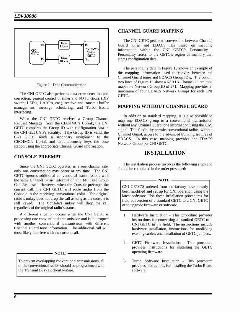
The CNI GETC also performs data error detection andcorrection, general control of timer and I/O functions (DIPswitch, LED’s, UART’s, etc.), receive and transmit buffermanagement, message scheduling, and Turbo Boardinterfacing.
When the CNI GETC receives a Group ChannelRequest Message from the CEC/IMC’s Uplink, the CNIGETC compares the Group ID with configuration data inthe CNI GETC’s Personality. If the Group ID is valid, theCNI GETC sends a secondary assignment to theCEC/IMC’s Uplink and simultaneously keys the basestation using the appropriate Channel Guard information.
CONSOLE PREEMPT
Since the CNI GETC operates as a one channel site,only one conversation may occur at any time. The CNIGETC ignores additional conventional transmissions withthe same Channel Guard information and Multisite GroupCall Requests. However, when the Console preempts thecurrent call, the CNI GETC will route audio from theConsole to the receiving conventional radio. The originalradio’s unkey does not drop the call as long as the console isstill keyed. The Console’s unkey will drop the callregardless of the original radio’s status.
A different situation occurs when the CNI GETC isprocessing one conventional transmission and is interruptedwith another conventional transmission with differentChannel Guard tone information. The additional call willmost likely interfere with the current call.
CHANNEL GUARD MAPPING
The CNI GETC performs conversions between ChannelGuard tones and EDACS IDs based on mappinginformation within the CNI GETC’s Personality. Personality refers to the GETC’s region of memory thatstores configuration data.
The personality data in Figure 13 shows an example ofthe mapping information used to convert between theChannel Guard tones and EDACS Group ID’s. The bottomtwo lines of Figure 13 show a 67.0 Hz Channel Guard tonemaps to a Network Group ID of 271. Mapping provides a maximum of four EDACS Network Groups for each CNIGETC.
MAPPING WITHOUT CHANNEL GUARD
In addition to standard mapping, it is also possible tomap one EDACS group to a conventional transmissionwithout any Channel Guard tone information using the CASsignal. This flexibility permits conventional radios, withoutChannel Guard, access to the advanced trunking features ofEDACS. In this case, mapping provides one EDACSNetwork Group per CNI GETC.
INSTALLATION
The installation process involves the following steps andshould be completed in the order presented:
1. Hardware Installation - This procedure providesinstructions for converting a standard GETC to aCNI GETC in the field. The instructions includehardware installation, instructions for modifyingexisting cables, and installation of GETC jumpers.
2. GETC Firmware Installation - This procedureprovides instructions for installing the GETCoperating firmware.
3. Turbo Software Installation - This procedureprovides instructions for installing the Turbo Boardsoftware.
Figure 2 - Data Communication
To prevent overlapping conventional transmissions, allof the conventional radios should be programmed withthe Transmit Busy Lockout feature.
NOTE
CNI GETC’S ordered from the factory have alreadybeen modified and set up for CNI operation using thelatest software. Use these installation procedures forfield conversion of a standard GETC to a CNI GETCor to upgrade firmware or software.
NOTE
LBI-38986
6

EQUIPMENT REQUIRED
The following equipment and software may be requiredto modify and configure the CNI GETC:
IBM compatible PC with at least 640K memory,monitor, and keyboard.
• Hard disk is recommended; but, not required.
• Serial Port configured as either COM1 or COM2.
• TQ-3360 programming cable.
• Male DB-25 to female DB-9 adapter.
• Software distribution diskette 344A4414.
• Oscilloscope.
• Standard hard tools.
• Temperature controlled soldering station.
HARDWARE INSTALLATION
Typically, a CNI GETC is installed in the repeatercabinet, just above the repeater’s radio assembly, usinghardware kit 19A130031G30. The tray containing the sub-assemblies is mounted within a slide out shelf measuring1.75 inches high (one rack unit) by 19 inches wide.
Install the GETC Shelf into the repeater cabinet, refer tothe MASTR II, IIe, or MASTR III Application Assembly and Installation Diagrams for detailed information oninstalling the GETC Shelf. Installation or removal of theshelf sub-assemblies involves sliding the GETC tray out ofthe cabinet and into the service position. This positionallows access to the shelf’s sub-assemblies.
Observe basic safety precautions to prevent injury orequipment damage.
Logic Board Modification
The following steps provide instructions for modifyingthe GETC Logic Board. Materials for this modification areprovided in Hardware Kits 344A3845 and 344A4019. Foradditional GETC assembly and maintenance information,refer to LBI-38894 and LBI-38988.
1. Place the GETC shelf in the service position.
2. Disconnect all cables from the GETC Logic Board.
3. Remove the GETC Logic Board 19D904266 fromthe shelf. Refer to the GETC Service Manual LBI-38894 for detailed instructions for removing andinstalling the printed circuit board in the GETCshelf.
4. Solder an orange wire jumper 19A115663P4 (partof Hardware Kit 344A4019) from TP107 to J7-7. Route the wire as shown in Figure 4. This allowsaccess to the test point which will be covered bythe Turbo Board installation.
5. Solder the white wire 19A115871P22 (part ofHardware Kit 344A3845) between TP102 and J18-2 as shown in Figure 4. This essentially connectsthe output of the Low Speed Decode Filter to U1’sinterrupt line, INT0 as shown in Figure 3.
6. Reinstall the Logic Board into the GETC Shelfusing the installation instructions provided in LBI-38894. Omit the three (3) screws on the J3 end ofthe board (these will be used to secure the TurboBoard).
The modified circuit functions as follows:
The conventional received audio (VOL/SQ HI) entersthe GETC at J7-2. This audio includes sub-audible signalsthat represents the Channel Guard tone information. TheLow Speed Decode Filter removes the received audio androutes the Channel Guard tone information to U1, theGETC’s main processor.
The standard parallel input at U1-3 is unused in the CNIconfiguration. Instead, U1 processes the Channel Guardtone information using the interrupt line at U1-12. The CNIapplication also requires a jumper from J18 pin 1 to pin 2.
The CNI uses the signal at INT0 to convert aconventional transmission with Channel Guard toneinformation into a digital EDACS message representingGroup Call Assignments. This process results in theCEC/IMC seeing a normal EDACS Group Call channelassignment message based on the sub-audible ChannelGuard tone information embedded in a conventionaltransmission.
Observe precautions for handling
ELECTROSTATIC SENSITIVE DEVICES
CAUTION
Do Not install the jumper wire between TP107 and J7-7 when the CNI GETC is used in MASTR IIIrepeaters. If the wire was previously installed,disconnect it from J7-7.
NOTE
LBI-38986
7

Rockwell Modem Installation
The Rockwell Modem provides a high speedsynchronous serial interface between the CNI GETC andthe CEC/IMC’s Uplink. The CNI GETC uses the modem tosend and receive serial digital data representing GIDinformation, polling messages, keying messages, andchannel assignments. Data transfer rates are typically 9600bits per second (bps) using 3002 grade four-wire audiolines. Additional information on installing and testing themodem may be found in LBI-33031, LBI-38894, and LBI-38822.
Install the Rockwell Modem using the followingprocedure:
1. Insert the Rockwell Modem into J3 on the GETCBoard and align the mounting holes over theGETC shelf standoffs.
Figure 4 - Logic Board (19D904266) Modification
Figure 3 - Simplified Diagram of Modified Circuit
LBI-38986
8

2. Isolate the modem from the shelf by installing theeight (8) fiber washers (4035306P25, part ofHardware Kit 344A4019). Insert four (4) washersbetween the modem and the shelf standoffs andplace the other four (4) washers on top of themodem board over the mounting holes.
3. Secure the modem by installing two screws (leftover from the Logic Board installation) through thewashers and modem board into the standoffslocated on the end opposite J3.
Turbo Board Installation
The Turbo Board provides the CNI with additionalmemory and processing capability through dual 8051 basedprocessors and support circuitry. It primarily providesadditional processing power. However, it also provides realtime debug capability during development, testing, andtroubleshooting.
The Turbo Board uses mostly surface mountedcomponents and mounts on stand offs above the GETCLogic Board. Electrical connections are made through a 28conductor ribbon cable on the Turbo Board to the XU3socket on the GETC Logic Board. Installation of a smallmechanical shield above the Turbo Board protects it frominadvertent damage when sliding the GETC drawer in andout of the cabinet. Additional information on the TurboBoard assembly and maintenance instructions for the boardmay be found in LBI-38822.
Use the following procedures to install the Turbo Board.Mounting hardware for the Turbo Board is contained inHardware Kit 344A4019.
1. Remove U3 (19A705558P1) from the XU3 socketon the GETC Logic Board. Observe precautionsfor handling electrostatic sensitive devices
2. Bend over or slightly move any components on theLogic Board whose height will interfere with theTurbo Board installation.
3. Install three (3) threaded spacers 19B201955P9 inplace of the screws omitted when Logic Board wasreinstalled.
4. Install two (2) threaded spacers 19B201955P9through the modem and into the shelf standoffsnext to J3.
5. Align the Turbo Board holes over the threadedspacers installed in steps 3 and 4 (orient the TurboBoard so connectors J2 and J3 are toward the rearof the GETC Shelf).
6. Secure the Turbo Board by installing two (2) panhead screws N80P13004B6 and two (2) lockwashers N404P13B6 through the board and intothe threaded spacers located near the front of theGETC Shelf (near S1 and Y1).
7. Install three threaded spacers 19B201955P9through the Turbo Board into the remainingspacers. These will be used to mount the guard.
8. Install the guard 19B802166P1 using three (3) flathead screws N404P13B6. The guard protects theTurbo Board from inadvertent damage whensliding the GETC Shelf in and out of the serviceposition.
9. Plug the ribbon cable from J1 on the Turbo Boardinto the XU3 socket on the GETC Logic Board.
10. Install the harness assembly, 19C337712G1, bysliding the P2/P3 end of the harness through thehole provided into the back of the GETC shelf.
11. Connect the 19C337712G1 Harness P2 and P3 tothe J2 and J3 Turbo Board connectors,respectively.
12. Secure the harness to the GETC shelf usingretaining strap 19J706152P5.
13. Mount the other end of the harness on the rear ofthe GETC Shelf. Secure the J103/J104 supportbracket to the shelf using the two (2) nut clips7160861P33 and self tapping screws19A134011P1 included with the harness.
When the installation is complete, examine the GETCShelf for any loose hardware. You may now proceed tomodify and reconnect the GETC cables.
The modem must be insulated from the shelf mountingstandoffs using eight washers. Four washers mount ontop of the modem’s printed circuit board and fourwashers mount on the bottom of the modem’s printedcircuit board.
NOTE
LBI-38986
9

GETC Cable Modifications
Use the following procedures to modify and reconnectcables in the CNI GETC. Be sure to follow the correctprocedures. Instructions titled MASTR II or IIe are for CNIGETC’s installed in MASTR II or MASTR IIe repeaters,instructions titled MASTR III are for CNI GETC’s installedin MASTR III repeaters only.
MASTR II & IIe
The following procedure provides instructions formodifying the cables when the CNI GETC (optionSTCP3Z) is used with a MASTR II or IIe repeater. Materials for the modification are provided as part of theHardware Kit 344A3845G1.
1. Mount the Terminal block, 19C301087P10, on theback of the GETC Shelf using the four (4) screws,N80P13007B6, and two (2) nuts, 7160508P2provided. Refer to Figure 5.
2. Disconnect the two (2) pairs of twisted wireconnected to P26-6, P26-7, P26 8 and P26-9 (partof cable harness 19C320811G15/G16) from theBackplane (19D417214) TB1201-18, -17, 11, and10 or from the Control Panel (19B234871) or MIIeBackplane (19D902459) TB1201-5, -2, -3, and -4respectively.
3. Connect the pair from P26-8 and P26-9 to theterminal block terminals 1 and 2 respectively. Thisis the GETC Transmit Data pair, see Figure 6.
4. Connect the pair from P26-6 and P26-7 to theterminal block terminals 3 and 4 respectively. This is theGETC Receive Data pair.
5. Connect the harness assembly (19C320811) plugP26 to the GETC Logic Board connector J6.
6. Connect the harness assembly (19C320811) plugP27 to the GETC Logic Board connector J7.
7. Connect the harness assembly (19C320811) plugP10 to the GETC Logic Board connector J10.
8. Connect the harness assembly (19C336863) plugP8 to the GETC Logic Board connector J8.
9. Connect the harness assembly (part of 19C320811and 19C336863) plug P19 to the GETC LogicBoard connector J19.
10. Connect the Regulator Board harness assembly(A2W1) plug P1 to the GETC Logic Boardconnector J27.
MASTR III
The following procedure provides instructions formodifying the cables when the CNI GETC is used with aMASTR III repeater. Materials for the modification areprovided as part of the MIII option SXCP5T.
1. Route the header (P26) on the Harness19C337792P1 through the terminal block hole andmount the terminal block to the back of the GETCShelf using the four (4) screws, N80P13007B6,and two (2) nuts, 7160508P2 provided. Refer toFigure 5.
Figure 5 - GETC Shelf (Rear View)
Modification of the GETC for use with MASTR II(IIe) and MASTR III repeaters differ. Use theprocedure applicable to the type of repeater associatedwith the CNI GETC.
NOTE
On MASTR IIe stations only, using wire harness19C320811G16. Cut the solid white jumpersconnected from P27-14 to P27-15 and from P27-6 toP27-16.
NOTE
LBI-38986
10
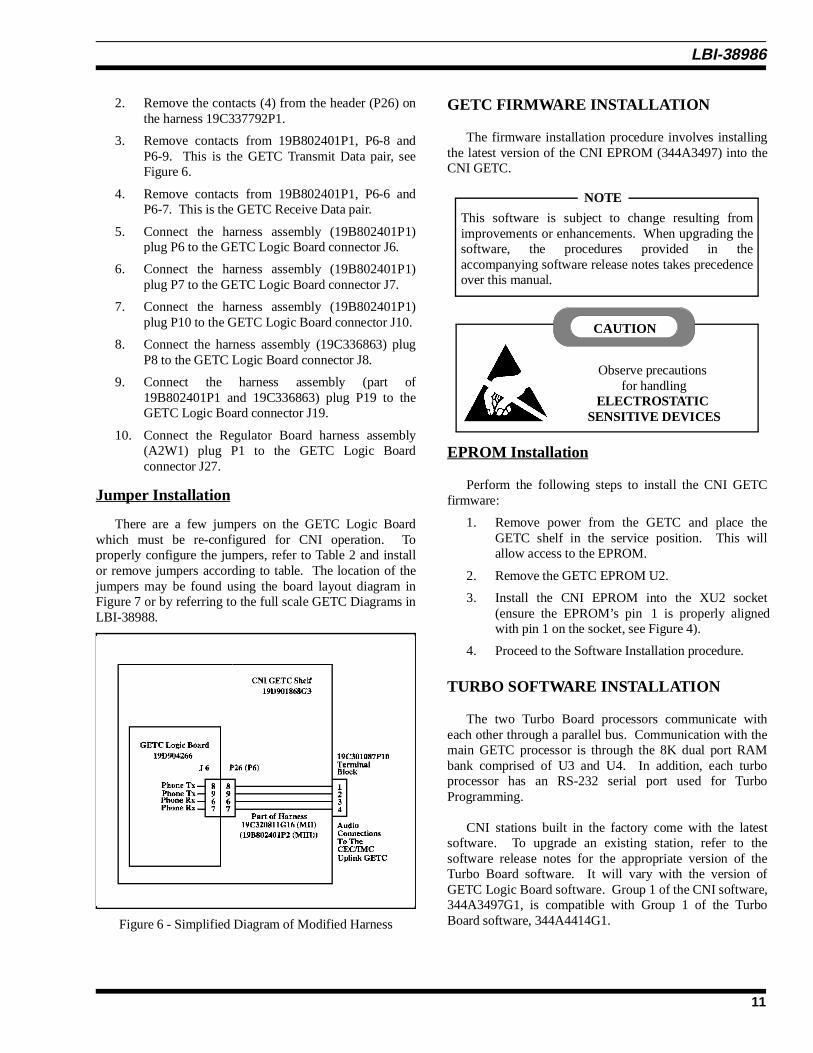
2. Remove the contacts (4) from the header (P26) onthe harness 19C337792P1.
3. Remove contacts from 19B802401P1, P6-8 andP6-9. This is the GETC Transmit Data pair, seeFigure 6.
4. Remove contacts from 19B802401P1, P6-6 andP6-7. This is the GETC Receive Data pair.
5. Connect the harness assembly (19B802401P1)plug P6 to the GETC Logic Board connector J6.
6. Connect the harness assembly (19B802401P1)plug P7 to the GETC Logic Board connector J7.
7. Connect the harness assembly (19B802401P1)plug P10 to the GETC Logic Board connector J10.
8. Connect the harness assembly (19C336863) plugP8 to the GETC Logic Board connector J8.
9. Connect the harness assembly (part of19B802401P1 and 19C336863) plug P19 to theGETC Logic Board connector J19.
10. Connect the Regulator Board harness assembly(A2W1) plug P1 to the GETC Logic Boardconnector J27.
Jumper Installation
There are a few jumpers on the GETC Logic Boardwhich must be re-configured for CNI operation. Toproperly configure the jumpers, refer to Table 2 and installor remove jumpers according to table. The location of thejumpers may be found using the board layout diagram inFigure 7 or by referring to the full scale GETC Diagrams inLBI-38988.
GETC FIRMWARE INSTALLATION
The firmware installation procedure involves installingthe latest version of the CNI EPROM (344A3497) into theCNI GETC.
EPROM Installation
Perform the following steps to install the CNI GETCfirmware:
1. Remove power from the GETC and place theGETC shelf in the service position. This willallow access to the EPROM.
2. Remove the GETC EPROM U2.
3. Install the CNI EPROM into the XU2 socket(ensure the EPROM’s pin 1 is properly alignedwith pin 1 on the socket, see Figure 4).
4. Proceed to the Software Installation procedure.
TURBO SOFTWARE INSTALLATION
The two Turbo Board processors communicate witheach other through a parallel bus. Communication with themain GETC processor is through the 8K dual port RAMbank comprised of U3 and U4. In addition, each turboprocessor has an RS-232 serial port used for TurboProgramming.
CNI stations built in the factory come with the latestsoftware. To upgrade an existing station, refer to thesoftware release notes for the appropriate version of theTurbo Board software. It will vary with the version ofGETC Logic Board software. Group 1 of the CNI software,344A3497G1, is compatible with Group 1 of the TurboBoard software, 344A4414G1.Figure 6 - Simplified Diagram of Modified Harness
This software is subject to change resulting fromimprovements or enhancements. When upgrading thesoftware, the procedures provided in theaccompanying software release notes takes precedenceover this manual.
NOTE
Observe precautions for handling
ELECTROSTATIC SENSITIVE DEVICES
CAUTION
LBI-38986
11

This procedure provides instructions for programmingthe Turbo Board installed in the CNI GETC. Theinstallation process uses the software diskette 344A4414, anIBM compatible personal computer (PC), and aninterconnecting cable (TQ-3360).
The PC reads data from the files on the 344A4414diskette and transfers the data to the Turbo Boardmicroprocessor through connectors J103 and J104 at therear of the GETC Shelf.
Running the "load1e.exe" executable program seriallymoves data from the "1etop.hex" and "1ebot.hex" files tothe code segment of the Turbo Board’s memory.
The "1ecrc.hex" file provides Cyclical RedundancyCheck (CRC) information for use in error checking andverification during the file transfer or "programming"process. Any errors encountered during this proceduregenerally indicate a defective communication link betweenthe PC and Turbo Board.
Preparation
Prepare the PC for programming the CNI GETC TurboBoard by performing the following steps:
1. Connect the TQ-3360 programming cable from thePC’s serial port connector to the GETC Shelfconnector J104 (see Figure 8). (A DB-25 to DB-9adapter may be needed.)
2. Using standard DOS commands or a software filemanager, create a directory named "LOAD1E" onthe PC’s hard drive.
3. Make "LOAD1E" the current default directory andcopy the following files from the software disketteinto the "LOAD1E" directory:
• load1e.exe
• 1etop.hex
• 1ecrc.hex
• 1ebot.hex
4. Move the Turbo Board run/load switches S2 andS3 to the load position (toward the front of theGETC shelf). The front position of S2 and S3places the processors U1 and U2 into theprogramming mode. If either switch is alreadytoward the front, move the switch to the rear andthen back to the front position.
5. The Turbo Board LEDs D1 and D2 should turnOFF indicating that the Turbo Board is in theprogramming mode.
Programming Mode
This procedure downloads the Turbo Board software tothe microprocessors U1 and U2 on the Turbo board.
1. Execute the "load1e.exe" program on the PC andfollow the on screen instructions.
The "load1e.exe" program loads the file"1etop.hex" into the Turbo Board’s upper half ofmemory for use by the top processor U1.
2. Monitor the PC’s on screen instructions andprompts.
3. When directed, move the TQ-3360 programmingcable from the GETC Shelf J104 to J103.
4. The PC will indicate it is loading the "1ebot.hex"file into the Turbo Board’s lower half of memoryfor use by the bottom processor U2.
Normal Mode
Upon successful completion of the programming mode,the PC displays a "FINISHED" message. It will alsoprovide instructions to switch S2 and S3 to the rear positionfor normal operation.
If an error occurs, check connectors and cables. CycleS2 and S3 from the front position, to the rear position,and again to the front position. If the PC continues toindicate an error, refer to the Turbo BoardMaintenance Manual LBI-38822.
NOTE
Re-programming the GETC Turbo Board will not alterpreviously stored Personality Data. When PersonalityData is present, "load1e.exe" clears and performs CRCfunctions over the code portion of memory only.
NOTE
LBI-38986
12

Figure 7 - CNI GETC (19D904266) Jumper Locations
Figure 8 - Turbo Board Programming
LBI-38986
13

Table 2 - Jumper Settings
Jumper setting for CNI GETC (19D904266 ONLY).
JumperPosition
WidebandCNI
GETC
Narrow bandCNI
GETC FUNCTION
P11 1&2 1&2 Enables Receive Data from 9600 baud modem board.
P12 1&2 1&2 Enables Clear-To-Send (CTS) from 9600 baud modem board.
P13 1&2 1&2 BSL Tx output to BSL Rx input.
P14 1&2 1&2 Master site controller path selection enable.
P15 1&2 1&2 Backup site controller path selection enable.
P16 1&2 1&2 BSL selection enable.
P17 1&2 1&2 LSD encode path enable.
P18 1&2 1&2 LSD decode path enable.
P20 OMIT OMIT
P21 1&2 1&2 Enable high-speed data acquisition rate control, HSACQ.
P24 1&2 1&2 BSL selection (Failsoft) enable.
P25 1&2 1&2 LSD encode path enable.
P26 1&2 1&2 Lock-detect path enable.
P28 1&2 1&2 Sync line input path enable.
P29 1&2 1&2 Enable site controller RxD, J8-4.
P44 1&2 1&2 Use for 256K or 512K EPROM.
P46 1&2 1&2 Used for normal communications.
P47 1&2 1&2 BSL select.
P48 1&2 1&2 BSL select.
P50 1&2 1&2 Enable tone control for voted system
P51 OMIT OMIT
P52 2&3 2&3 TxD polarity invert.
P53 1&2 1&2 RxD polarity normal.
P54 1&2 1&2 Enable MODCNTL local control.
P55 OMIT OMIT
P60 1&2 1&2 Enables HSD path.
P61 2&3 2&3 Use for 512K EPROM.
P62 1&2 2&3 1 & 2 selects 11.0592 MHz clock Freq. for 9600 baud data (Wideband).2 & 3 selects 5.5296 MHz clock freq. for 4800 baud data (Narrow band).
P63 OMIT 1&2 1 & 2 for 4800 baud (900 MHz Narrow band)
P64 OMIT 1&2 1 & 2 for 4800 baud (900 MHz Narrow band)
P65 OMIT 1&2 1 & 2 for 4800 baud (900 MHz Narrow band)
P66 OMIT 1&2 1 & 2 for 4800 baud (900 MHz Narrow band)
P67 OMIT OMIT
P68 1&2 1&2 Selects Local (on)/Remote (off) control of station PTT.
P69 OMIT OMIT
P71 1&2 1&2 Enables phone modem RTS control.
P72 1&2 1&2 Selects internal oscillator.
P73 2&3 2&3 Enables NOR gate U22B for EDACS applications.
P74 2&3 2&3 CAS polarity normal.
Legend: LSD = Low Speed Data BSL = Backup Serial Link RxD = Receive Data HSD = High Speed Data MSL = Main Serial Link TxD = Transmit Data
LBI-38986
14
1. Move switches S2 and S3 to the "run" position(toward the back of the GETC shelf).
2. Press S4 to reset the GETC.
3. The Turbo Board LEDs, D1 and D2, will lightindicating the station code is executing.
4. Disconnect the TQ-3360 programming cable uponsuccessful completion of the programmingprocedure.
For additional information on programming the TurboBoard, refer to the Turbo Board Maintenance Manual LBI-38822 and Software Release Note SRN-1062.
CONFIGURATION
The configuration process involves the followingoperations:
1. Personality Programming - Use this procedure toset up the CNI GETC Personality.
2. Repeater Personality - Describes the procedure forsetting up the MASTR III or IIe RepeaterPersonality (not required for MASTR II).
3. Dip Switch Settings - Provides instructions forsetting DIP switches for CNI operation.
4. Modem Alignment - Provides Instructions foradjusting phone line levels.
5. CEC/IMC Personality Configuration - Describesthe procedures necessary for setting up the SystemManager and CEC/IMC for Conventional Networkand Group ID’s.
PERSONALITY PROGRAMMING
Personality refers to the system configuration datastored in the GETC’s memory. The GETC’s Personalityincludes system configuration information such as channelfrequencies, call parameters, operating modes, andidentification information.
The Personality Programming process stores thePersonality data in EEPROM U35 on the GETC LogicBoard (CNI GETC’s with EPROM 344A3497G1). Thisprocess involves using the TQ-3357 (Version 3.00 or later)GETC Shelf PC programming Guide which includes theprogramming software.
Programming Set-up
Prepare the PC for Personality Programming byperforming the following steps:
1. Connect the TQ-3360 programming cable from thePC’s serial port connector (COM1/COM2) to theCNI GETC Shelf connector J100 (see Figure 10). (A DB-25 to DB-9 adapter may be needed.)
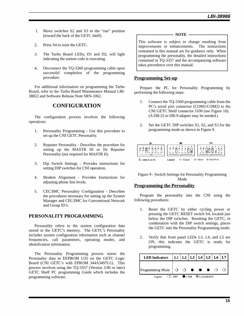
2. Set the GETC DIP switches S1, S2, and S3 for theprogramming mode as shown in Figure 9.
Programming the Personality
Program the personality into the CNI using thefollowing procedures:
1. Reset the GETC by either cycling power orpressing the GETC RESET switch S4, located justbelow the DIP switches. Resetting the GETC, incombination with the DIP switch settings, placesthe GETC into the Personality Programming mode.
2. Verify that front panel LEDs L3, L4, and L5 areON, this indicates the GETC is ready forprogramming.
This software is subject to change resulting fromimprovements or enhancements. The instructionscontained in this manual are for guidance only. Whenprogramming the personality, the detailed instructionscontained in TQ-3357 and the accompanying softwaretakes precedence over this manual.
NOTE
Figure 9 - Switch Settings for Personality ProgrammingMode
LBI-38986
15
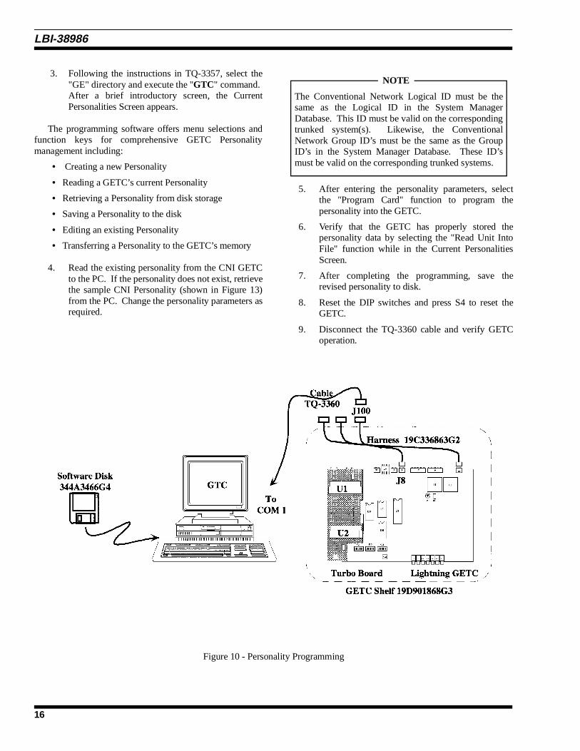
3. Following the instructions in TQ-3357, select the"GE" directory and execute the "GTC" command. After a brief introductory screen, the CurrentPersonalities Screen appears.
The programming software offers menu selections andfunction keys for comprehensive GETC Personalitymanagement including:
• Creating a new Personality
• Reading a GETC’s current Personality
• Retrieving a Personality from disk storage
• Saving a Personality to the disk
• Editing an existing Personality
• Transferring a Personality to the GETC’s memory
4. Read the existing personality from the CNI GETCto the PC. If the personality does not exist, retrievethe sample CNI Personality (shown in Figure 13)from the PC. Change the personality parameters asrequired.
5. After entering the personality parameters, selectthe "Program Card" function to program thepersonality into the GETC.
6. Verify that the GETC has properly stored thepersonality data by selecting the "Read Unit IntoFile" function while in the Current PersonalitiesScreen.
7. After completing the programming, save therevised personality to disk.
8. Reset the DIP switches and press S4 to reset theGETC.
9. Disconnect the TQ-3360 cable and verify GETCoperation.
Figure 10 - Personality Programming
The Conventional Network Logical ID must be thesame as the Logical ID in the System ManagerDatabase. This ID must be valid on the correspondingtrunked system(s). Likewise, the ConventionalNetwork Group ID’s must be the same as the GroupID’s in the System Manager Database. These ID’smust be valid on the corresponding trunked systems.
NOTE
LBI-38986
16

REPEATER PERSONALITY
It may be necessary to reprogram the personality of theMASTR III or IIe repeater. Refer to TQ-3353 (Version 9.0or later). Select “GETC” from the Control Screen to accessthe GETC Data Screen.
Follow the instructions for making a change to theCurrent Personalities Screen and select the CNI field. Setting the field selection to YES disables the High SpeedData audio routing and routes the Channel Guard tones toand from the CNI GETC.
Use the procedures described in TQ-3353 and downloadthe revised personality data into the MASTR III or IIerepeater.
DIP SWITCH SETTINGS
Three DIP switches on the GETC Logic Board must beproperly set for CNI operation. S1-1 thru S1-7 and S2-1thru S2-4 set the CNI’s transmitting frequency for MASTRII and IIe repeaters. S3-1 through S3-5 select the channelnumber which is normally set to Channel One.
Set the GETC DIP switches using the followingprocedures (refer to Figure 11):
1. Set S1-1 thru S1-7 and S2-1 thru S2-4 to therepeater’s operating frequency (except MASTRIII). Refer to the Station GETC manual, LBI-38988, for the DIP switch settings whichcorrespond to the operating frequency.
2. Set S1-8 to the Closed position (not used).
3. Set S2-5 to the Closed position (ConventionalFailsoft enabled).
4. Set S2-6 thru S2-8 to the Closed position.
5. Set S3-1 to Open and S3-2 thru S3-5 to the Closedposition. This sets the CNI GETC for operation onchannel number 1.
6. Set S3-6 thru S3-8 to the Closed position. Thissets the GETC to the normal trunked messagemode.
MODEM ALIGNMENT
Use the following steps to set up the basic audio linelevels. If the CNI GETC is linked to a multisite systemother than the CEC/IMC (i.e. Data Gateway), differentlevels may be required. Consult the applicable systeminstallation manual for the required levels.
1. Ensure jumpers are installed on J11 and J12 pins 1& 2.
2. Apply power to the GETC.
3. Adjust the receive level by monitoring U18 pin 1(refer to Figure 12) and adjusting the receive levelpotentiometer R1 (located on the GETC LogicBoard) for 400 mVpp as measured with anoscilloscope (85 mVrms if using an RMSVoltmeter).
4. Verify the presence of demodulated signal data atmonitor jumper wire for MASTR II or IIe.
5. Adjust the transmit level potentiometer R2 for themaximum output level allowed by the phone line,microwave link, or equivalent communication line.For telephone lines linking the CNI GETC to theCEC/IMC Uplink GETC, adjust R2 for .77 Vrms(0 dBm) measured across J6-8 and J6-9 (TB10-1and 2). For microwave links, adjust R2 for -10dBm across J6-8 and J6-9.
6. Initialize the modem by pressing S4 (on the GETCLogic Board) to reset the CNI GETC or cycle theGETC Shelf’s operating power.
7. Verify proper modem initialization and operationby observing the CNI GETC front panel LED’s. Proper operation is indicated by illuminating LEDindicator L1.
Be sure the DIP switch settings correspond to thePersonality data created.
NOTE
In MASTR III repeaters the operating frequency isprogrammed directly into the MASTR III’spersonality. Set S1-1 thru S1-7 and S2-1 thru S2-4 tothe Closed position.
NOTE
Figure 11 - CNI GETC Switch Settings
LBI-38986
17

Figure 12 - GETC Phone Line Level Adjustments
LBI-38986
18

Figure 13 - Sample CNI Personality
LBI-38986
19

CEC/IMC PERSONALITYCONFIGURATION
At the System Manager (refer to LBI-38984), configurethe CNI groups as TRACKED. This enables the CEC/IMCto route only Wide Area Group Calls to the CNI GETCcorresponding to the last conventional CNI transmission. Also use the System Manager to set up the Logical ID’s forthe conventional repeaters. These ID’s must be valid on thetrunked systems for patching and should be the same ID’sset in the GETC Personality during the CNI GETCPersonality Programming.
Configuring the CNI as Forced in the CEC/IMC’sPersonality will result in the CNI receiving Wide AreaGroup Calls, regardless of the last call on the repeater. Remember, the CNI responds only to the Group ID’sconfigured in the CNI’s Personality.
A site must be set up in the CEC/IMC using theCEC/IMC Manager (MOM PC). It needs one (1) slot forCNI. Audio Board 1, Channel 1 should be used. We alsorecommend that CNI Systems not be Confirmed. Refer toLBI-39024.
The CEC/IMC bypasses the CNI system with othermultisite calls making the CNI channel available for userswithin the CNI system coverage area for System Managerprogramming.
LED INDICATORS
The CNI’s front panel LEDs indicate the CNI’soperational state (refer to Table 3). Upon power up, L1turns ON indicating proper CNI operation. For NarrowBand CNI GETC’s, L3 also turns ON. These LED’s willcontinue to remain ON.
When a conventional radio transmission with validChannel Guard tone information is initiated, L6 alsoilluminates.
When the CNI GETC receives a valid Group CallChannel Request from the CEC/IMC’s Uplink GETC,LED’s L2 and L6 illuminate.
TEST AND ALIGNMENT
This section provides instructions for performing afunctional checkout of the CNI GETC and repeater usingradios programmed for CNI operation.
In the event the repeater requires minor adjustments, thissection also provides supplemental information for settingup MASTR II, IIe, or III repeaters for CNI operation.
FUNCTIONAL CHECKOUT
Verify the proper installation of the CNI software byreading the GETC’s coded LED display.
Look for normal operation while placing several testcalls. Test the system’s fault tolerance by keying a radiothen turning the radio power off without releasing the PTTswitch. The channel should drop the call and return to anidle state within two to three seconds.
Locally Initiated Call
This procedure assumes that the test radios being usedhave their personalities set to the proper Channel Guardtones and are operating in the conventional mode.
1. Cycle power the repeater (or reset the GETC). Therepeater should default to the Idle State.
Table 3 - Front Panel LED State Indicators
LBI-38986
20

2. Verify the CNI GETC LED’s indicate the Idle State(see Table 3), L1 is ON, L2 thru L7 are OFF. (IfNarrow Band repeater, L3 is also ON).
3. Initiate a call from the test radio to the console.
4. Verify that the CNI GETC switches to theConventional Call mode and indicators L1 and L6turn ON (also L3 for Narrow Band repeaters).
This indicates the CNI GETC has decoded theChannel Guard tone and has sent the Group CallAssignment message to the CEC/IMC UplinkGETC
5. Verify that voice can be heard on both radios.
6. Unkey the radio and verify that the CNI GETCreturns to the Idle State.
Multisite Initiated Call
1. Initiate a multisite call or a console call to a radioassigned to the CNI repeater.
2. When the call is received, verify that CNI GETCswitches to the Trunked Call mode and indicatorsL1, L2, and L6 turn ON (also L3 for Narrow Bandrepeaters).
This indicates the CNI GETC has received aGroup Channel Request Message with a validGroup ID.
3. Verify that voice can be heard on the radio.
4. When the call is finished, verify that the CNIGETC returns to the Idle State.
REPEATER ADJUSTMENTS
The following adjustment information supplements thebasic repeater alignment instructions found in the associatedrepeater maintenance or installation manuals. Theseprocedures should be performed only when the repeater’sperformance is in doubt.
MASTR II and IIe Repeaters
Steps 1 thru 4 are for setting the TX MOD ADJUST inMASTR IIe repeaters only. For MASTR II repeaters, skipto step 5.
1. Key the transmitter by grounding DELAYED PTT(J931-8). Do not apply any audio to themicrophone input so no microphone modulation isobtained.
2. Connect an Audio Oscillator between TX AUDIOHI (P8-6) and TX AUDIO LO (P8-5) and adjust
the oscillator for an output level of 1.0 Vrms at1000 Hz.
3. Set the MOD ADJUST pot on the transmitterexciter for 3.75 kHz deviation.
4. Unkey the transmitter by removing the groundfrom J931-8 and disconnect the Audio Oscillator.
The following steps are applicable to the MASTR II andMASTR IIe repeaters.
5. Verify the CNI Software 344A3497 is installed(refer to the GETC FIRMWARE INSTALLATIONsection).
6. Verify the jumper wire has been installed betweenTP102 and J18-2 on the GETC Logic Board (referto Figure 4 in the Logic Board Modificationsection).
7. Verify the GETC DIP switches are properly set forCNI operation (refer to Figure 11 in the DIPSWITCH SETTING section).
8. Ensure the CNI GETC’s personality ChannelGuard Mapping has one Conventional NetworkChannel Guard set for 123.0 Hz. (Refer to thepersonality example, Figure 13, in theProgramming The Personality section.)
9. Verify the jumpers are properly installed as shownin Table 2.
10. Turn ON the Station Power Supply and verify L1on the GETC is turned ON. This confirms properoperation of the modem. (For 900 Mhzapplications, both L1 and L3 will be ON.)
11. Apply an “on channel” RF signal, modulated witha 123.0 Hz tone at 0.75 kHz deviation. Verify thatindicator L6 turns ON. Verify the transmitteroutput deviation is 0.75 kHz • 50 Hz. Adjust theCG ADJUST POT on the receiver/exciter door ifnecessary.
12. Modulate the signal with an additional 1000 Hztone at 3.0 kHz of deviation. Verify the transmitteroutput deviation is 3.75 kHz • 100 Hz. AdjustPOT 2 (TX POT at MASTR IIe Control Shelf) ifnecessary.
13. Adjust the POT 1, Remote Audio Level, for 0 dBminto 600 ohms.
14. Remove the 1000 Hz tone from the signalgenerator, but leave Channel Guard (123.0 Hz)tone ON.
15. Apply a 2175 Hz tone at -30 dBm (25 mV rms) toTB1201-2,5. Verify that indicator L2 turns ON.
LBI-38986
21

Apply an additional 1000 Hz tone at 0 dBm. Verify the output deviation of the transmitter is3.75 kHz • 100 Hz. If necessary, adjust POT 7,Compressor Gain Pot.
16. Disconnect the signal from the remote audioreceive ports (TB1201-2,5). Verify that indicatorL2 turns OFF.
17. Re-apply the 1000 Hz tone to the signal generator(removed in step 14) and verify the repeater is nowrepeating the 1000 Hz tone and 123.0 Hz ChannelGuard tone at 3.75 Hz deviation.
18. Disconnect the RF signal generator and verify thatonly indicator L1 is ON (L1 and L3 for 900 Mhzapplications).
MASTR III Repeaters
The following adjustment information supplements thebasic repeater alignment instructions found in the MASTRIII maintenance or installation manuals.
1. Verify the CNI Software 344A3497 is installed(refer to the GETC FIRMWARE INSTALLATIONsection).
2. Verify the jumper wire has been installed betweenTP102 and J18-2 on the GETC Logic Board (referto Figure 4 in the Logic Board Modificationsection).
3. Verify the GETC DIP switches are properly set forCNI operation (refer to Figure 11 in the DIPSWITCH SETTING section).
4. Ensure the CNI GETC’s personality ChannelGuard Mapping has one Conventional NetworkChannel Guard set for 123.0 Hz. (Refer to thepersonality example, Figure 13, in theProgramming The Personality section.)
5. Verify the jumpers are properly installed as shownin Table 2.
6. Turn ON the Station Power Supply and verify L1on the GETC is turned ON. This confirms properoperation of the modem
7. Apply an “on channel” RF signal, modulated witha 123.0 Hz tone at 0.75 kHz deviation (0.6 kHz ifNASPAC). Verify that indicator L6 turns ON. Verify the transmitter output deviation is 0.75 kHz± 50 Hz (0.6 kHz if NASPAC). Adjust the CG(Channel Guard) software pot if necessary.
8. Modulate the signal with an additional 1000 Hztone at 3.0 kHz of deviation(2.4 kHz if NASPAC).
Verify the transmitter output deviation is 3.75 kHz± 100 Hz (3.0 kHz if NASPAC).
9. Remove the 1000 Hz tone from the signalgenerator, but leave Channel Guard (123.0 Hz)tone ON.
10. Apply a 2175 Hz tone at -30 dBm (25 mV rms) toTB101-2,5 on the MIII T/R Shelf Interface Board. Verify that indicator L2 turns ON. Apply anadditional 1000 Hz tone at -10 dBm (245 mV rms).Verify the output deviation of the transmitter is3.75 kHz ± 100 Hz (3.0 kHz if NASPAC). Ifnecessary, adjust the deviation using the DI (DSPLine Input) software pot.
11. Disconnect the signal TB101-2,5. Verify thatindicator L2 turns OFF.
12. Disconnect the RF signal generator and verify thatonly indicator L1 is ON.
TROUBLESHOOTING
Refer to the Troubleshooting Chart in Figure 14 as aguide for troubleshooting the CNI configuration. Inaddition, the following steps provide additional help inisolating problem areas while troubleshooting.
1. Check the CNI’s Personality. Verify the followingis correct:
• Channel Frequency
• Group ID and Channel Guard Frequency pairsare correct.
• Repeater’s Logical ID
• Site ID
2. Check the Conventional Repeater. Verify that:
• Limited Channel Guard signal appears at TP 102.
• Channel Guard encode signal appears at J19-5.
3. Check CEC/IMC Data connections:
• CEC/IMC Data connections consist of 2 pairs of9600 Baud links. Make sure they are correctlyconnected. Refer CEC/IMC manual LBI-38662.
LBI-38986
22

4. Check CEC/IMC Switch Audio connections.
• This refers to audio connections between theCEC/IMC Switch and the CNI GETC orRepeater. Refer to CEC/IMC manualLBI-38662.
If the problem is isolated to the CNI GETC, refer to theGETC Maintenance Manual LBI-38894 for detailed boardlevel test procedures.
CNI INTERFACE REQUIREMENTS
Refer to Figure 15 for the required connections betweenthe CNI and a repeater, when using a repeater other thanEGE’s MASTR II (IIe) or MASTR III stations.
The CNI GETC requires the following voltages andsignals:
POWER (J10-1)(Ground, J10-2)
+13.8 Vdc, 2A
VOL\SQ HI (J7-2)(Vol/Sq LO, J7-1)
Unfiltered receiver audio,including Voice and ChannelGuard tone.
Once in the GETC, this signal isrouted to the Low Speed DataFilter where it is checked for thepresence of a Channel Guardtone.
Typically, the repeater is set upfor a 1 V rms output when an“on channel” RF signalmodulated with a 1000 Hz toneat 3 kHz deviation is applied.
Carrier Activated SQ.(RUS IN) (J7-14)
Input line should be set high (5Vdc) when the receiver isunsquelched by an “on channel”carrier.
The line is low when the receiveris squelched.
E & M Signalling voltage or Secur-it tonehold detect(Remote PTT IN, J7-9)
A ground (active low) needs tobe applied to the GETC whenthe repeater decodes a 2175 Hztone or E & M contact closure isused.
This signal (low) alerts theGETC to the presence of a callfrom a remote source(CEC/IMC) for the duration ofthe low condition.
The CNI GETC provides the following output signals:
Channel Guard tone (J19-5)
GETC outputs a 3 Vpp, EIARS-220A Channel Guard tone(67 Hz to 192.8 Hz) to therepeater.
Signal is sent for transmissionwith voice as an indicator ofvalid channel activity or to passon priority scan information.
Delay PTT (J6-1) This line is pulled low (4 mAO/C output) when the GETCwants to key the repeater’stransmitter for any reason.
REPEAT/REMOTEREM PTT OUT (J6-16)
Output is High (5 Vdc) forRepeat Audio.
Output is Low (0 Vdc) forRemote Audio.
CEC/IMC Switch levels:
Remote Audio Level(In & Out)
0 dBm, 0 Vdc offset
Impedance 600 ohms
E & M Signallingvoltage or 2175 Hz tone
-20 dBm
LBI-38986
23

CEC/IMC Data signals:
Data Rate 9600 baud
Transmit level 0.77 Vrms
Receive level 0.16 Vrms on J3A-32(U18A-1)
Repeater Configurations:
For Four Wire Tone Remote (transmit pair and receivepair), the repeater should be configured in such a way that:
• Allows the CNI GETC to key the transmitter.
• Transmits Channel Guard Tone generated by CNIGETC.
• Always routes the received audio to its remotereceive pair.
• Allows local or remote audio to be transmitteddepending on the REM PTT line.
LBI-38986
24

Figure 14 - CNI Troubleshooting Chart
TROUBLESHOOTING CHART
LBI-38986
25

INTERCONNECT DIAGRAM
Figure 15 - Typical CNI to Conventional Repeater Interface
LBI-38986
26
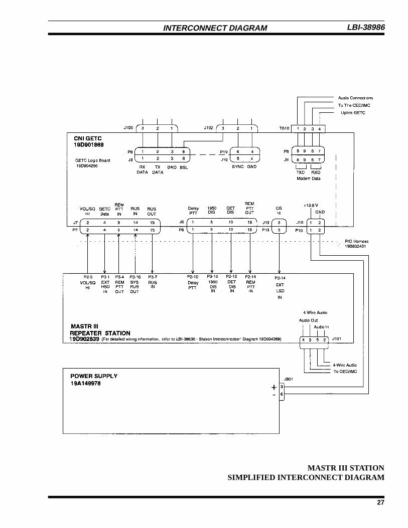
INTERCONNECT DIAGRAM
MASTR III STATIONSIMPLIFIED INTERCONNECT DIAGRAM
LBI-38986
27

INTERCONNECTION DIAGRAM
MASTR II, IIe STATIONSIMPLIFIED INTERCONNECT DIAGRAM
LBI-38986
28
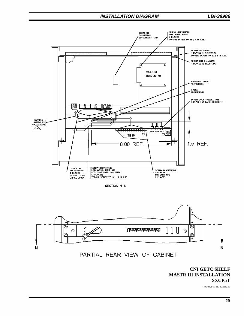
INSTALLATION DIAGRAM
CNI GETC SHELFMASTR III INSTALLATION
SXCP5T(19D902845, Sh. 30, Rev. 1)
LBI-38986
29

INSTALLATION DIAGRAM
CNI GETC SHELFMASTR II, IIe INSTALLATIONSTCP3Z(19D417483, Sh. 12, Rev. 27)
When installing GETC Panel 19D901868,Mount GETC Panel above Radio housing.If not CNI Application, connect 19C336861P2 sensor to transmitantenna connector. Remove wire from P19-5 on 19C320811 andinstall in P19-5 on 19C336863. Use Hardware Kit19A130031G30. For CNI Application, refer to Mod. Instruction344A3498P1, replace PROM Kit 19A149256 with PROM Kit344A3497 provided, after tune and test. On MIIe Stations, cut thesolid white jumper wires on harness 19C320811G16 from P27-14to P27-15 and P27-6 to P27-16.
Ericsson Inc.Private Radio SystemsMountain View RoadLynchburg, Virginia 245021-800-528-7711 (Outside USA, 804-528-7711) Printed in U.S.A.
LBI-38986