lbi-38985b - edacs site controller - repeater builder · alarm and control unit (acu) ......
TRANSCRIPT

LBI-38985B
ericssonzericssonz
Maintenance Manual
EDACS
Site Controller
LBI-38985B NOTICES
Copyright November 1993, Ericsson GE Mobile Communications Inc.
2
REVISION HISTORY
Revision Date Reason for Change
- Nov 1993 Original Release.
A Jan 1994 Changed numbering plan that identifies position of Application Software PROMs, and AC andDC Interconnection Diagrams.
B Jan 1996 Additional information and corrections for original equipment, and new information forGuardog, DB8860-based PMU, ELI (Enhanced Local Interconnect), Multiple ChannelPartition, Orion Test Unit, and MASTR III Alarms.
NOTICE!
This Manual covers Ericsson and General Electric products manufactured and sold by Ericsson Inc.
NOTICE!
Repairs to this equipment should be made only by an authorized service technician or facility designated by the supplier.Any repairs, alterations or substitution of recommended parts made by the user to this equipment not approved by themanufacturer could void the user’s authority to operate the equipment in addition to the manufacturer’s warranty.
NOTICE!The software contained in this device is copyrighted by Ericsson Inc. Unpublished rights are reserved under the copyrightlaws of the United States.
This manual is published by Ericsson Inc., without any warranty. Improvements and changes to this manual necessitated by typographical errors,inaccuracies of current information, or improvements to programs and/or equipment, may be made by Ericsson Inc., at any time and without notice. Suchchanges will be incorporated into new editions of this manual. No part of this manual may be reproduced or transmitted in any form or by any means,electronic or mechanical, including photocopying and recording, for any purpose, without the express written permission of Ericsson Inc.

CONTENTS LBI-38985B
3
TABLE OF CONTENTS
PAGESPECIFICATIONS ..................................................................................................................................... 11INTRODUCTION....................................................................................................................................... 12DESCRIPTION........................................................................................................................................... 13
STANDARD EQUIPMENT................................................................................................................ 13Cabinet .......................................................................................................................................... 13Exhaust Fan................................................................................................................................... 13Main AC Power Strip.................................................................................................................... 13Auxiliary AC Power Strip ............................................................................................................. 13EDACS Interface Panels ............................................................................................................... 13Downlink GETC ........................................................................................................................... 13Site Controller Computer .............................................................................................................. 15System Manager Modem............................................................................................................... 15DC Power Supply.......................................................................................................................... 15Uninterruptible Power Supply (UPS)............................................................................................ 15
OPTIONAL EQUIPMENT.................................................................................................................. 15Cabinets & Racks.......................................................................................................................... 15230V, 50 Hz Power....................................................................................................................... 15Power Monitor Unit (PMU) .......................................................................................................... 15Local Telephone Interconnect....................................................................................................... 16Redundant Downlink GETC ......................................................................................................... 16Alarm and Control Unit (ACU)..................................................................................................... 16Test Unit (TU)............................................................................................................................... 16Guardog......................................................................................................................................... 17
INSTALLATION........................................................................................................................................ 18CABINET ............................................................................................................................................ 18PROTECTIVE GROUND ................................................................................................................... 18AC POWER ......................................................................................................................................... 18INTERFACE PANEL #1 ..................................................................................................................... 18
Power Sensor Module ................................................................................................................... 18“RIC AUDIO” Modules................................................................................................................ 20“GETC DATA” Modules.............................................................................................................. 20“SERIAL MODULE” Module...................................................................................................... 21
INTERFACE PANEL #2 ..................................................................................................................... 21“DOWNLINK DATA” Module.................................................................................................... 22“PHONE LINE” Modules............................................................................................................. 22
DIRECT CONNECTIONS .................................................................................................................. 23ELI Local Telephone Interconnect................................................................................................ 23Alarm & Control Unit (ACU) ....................................................................................................... 24Test Unit (TU)............................................................................................................................... 25Guardog......................................................................................................................................... 25System Manager............................................................................................................................ 26
INITIAL POWER-UP.......................................................................................................................... 27

LBI-38985B CONTENTS
4
TABLE OF CONTENTS (Continued)
PAGEFULL-FEATURED TRUNKING ............................................................................................................... 28
SITE CONTROLLER STARTUP........................................................................................................ 28Initialization .................................................................................................................................. 28Request for Site Database.............................................................................................................. 28Switch Operational Mode of Site .................................................................................................. 28
GETC COMMUNICATION................................................................................................................ 28GETC Data Links.......................................................................................................................... 28Frame Sync Line (FSL) ................................................................................................................. 28
CONTROL CHANNEL SELECTION................................................................................................. 28Startup ........................................................................................................................................... 29Control Channel Failure ................................................................................................................ 29
WORKING CHANNEL ASSIGNMENTS .......................................................................................... 29Communication Modes.................................................................................................................. 29Call Sequence................................................................................................................................ 29
CALL VALIDATION.......................................................................................................................... 30CALL QUEUING................................................................................................................................. 30DOWNLINK SELECTION ................................................................................................................. 30SITE CONTROLLER FAILURE......................................................................................................... 31SITE CONTROLLER RECOVERY.................................................................................................... 31
SYSTEM MANAGER ................................................................................................................................ 32DATA LINK ........................................................................................................................................ 32
Protocol ......................................................................................................................................... 32Baud Rate ...................................................................................................................................... 32Data Link....................................................................................................................................... 32
PARAMETERS.................................................................................................................................... 32ACTIVITY REPORTS......................................................................................................................... 35
ALARMS..................................................................................................................................................... 36ALARM DETECTION ........................................................................................................................ 36
Site Controller ............................................................................................................................... 36Power Monitor Unit....................................................................................................................... 36Alarm & Control Unit.................................................................................................................... 36Test Unit........................................................................................................................................ 36Station GETC ................................................................................................................................ 37Downlink GETC............................................................................................................................ 37
ALARM MANAGEMENT .................................................................................................................. 38Channel Failure/Recovery ............................................................................................................. 38Polling Failure/Recovery............................................................................................................... 38Fault Tolerance Threshold............................................................................................................. 39ACU Display Panel ....................................................................................................................... 40
CRITICAL FAULT ALARMS............................................................................................................. 40Description .................................................................................................................................... 40System Requirements .................................................................................................................... 40Compatibility with PMU Option ................................................................................................... 40Channel Failure / Recovery ........................................................................................................... 41

CONTENTS LBI-38985B
5
TABLE OF CONTENTS (Continued)
PAGEALARM & CONTROL UNIT .................................................................................................................... 42
DESCRIPTION.................................................................................................................................... 42INPUTS................................................................................................................................................ 42OUTPUTS............................................................................................................................................ 42PARAMETERS ................................................................................................................................... 42
Alarm Inputs.................................................................................................................................. 42Control Outputs............................................................................................................................. 42
MESSAGING ...................................................................................................................................... 42OPERATION....................................................................................................................................... 42
Startup........................................................................................................................................... 42Alarm Inputs.................................................................................................................................. 43Control Outputs............................................................................................................................. 43ACU Front Panel Alarm Display .................................................................................................. 43System Manager Alarm Display.................................................................................................... 43
TEST UNIT................................................................................................................................................. 44DESCRIPTION.................................................................................................................................... 44
RANGR Test Unit......................................................................................................................... 44MDX Test Unit ............................................................................................................................. 44Orion Test Unit ............................................................................................................................. 44
PARAMETERS ................................................................................................................................... 44MESSAGING ...................................................................................................................................... 44OPERATION....................................................................................................................................... 45
Modes of Operation ...................................................................................................................... 45Background Test Calls .................................................................................................................. 45Recovery Test Calls ...................................................................................................................... 45
POWER MONITOR UNIT......................................................................................................................... 47DB8860-BASED PMU ........................................................................................................................ 47
Description.................................................................................................................................... 47System Requirements .................................................................................................................... 47Parameters..................................................................................................................................... 47
DB8843-BASED PMU ........................................................................................................................ 48Description.................................................................................................................................... 48System Requirements .................................................................................................................... 48Parameters..................................................................................................................................... 48
MESSAGING ...................................................................................................................................... 49OPERATION....................................................................................................................................... 50
Power Sensors ............................................................................................................................... 50PMU Activity ................................................................................................................................ 50Site Controller Activity ................................................................................................................. 50

LBI-38985B CONTENTS
6
TABLE OF CONTENTS (Continued)
PAGEGUARDOG ................................................................................................................................................. 52
DESCRIPTION.................................................................................................................................... 52INPUTS................................................................................................................................................ 52OUTPUTS............................................................................................................................................ 52OPERATION ....................................................................................................................................... 52
Automatic Reset Cycle .................................................................................................................. 52External Reset Disable Cycle ........................................................................................................ 53
LOCAL INTERCONNECT ........................................................................................................................ 54GENERAL ........................................................................................................................................... 54
Equipment Versions ...................................................................................................................... 54Parameters ..................................................................................................................................... 54Interconnect Timing Settings......................................................................................................... 57Toll Call Restrictions..................................................................................................................... 59Dedicated Lines............................................................................................................................. 59Interconnect Rotary Definition ...................................................................................................... 59
RIC / LIC INTERCONNECT .............................................................................................................. 59Description .................................................................................................................................... 59Additional Parameter..................................................................................................................... 60
ELI INTERCONNECT ........................................................................................................................ 60Description .................................................................................................................................... 60System Requirements .................................................................................................................... 60Additional Parameter..................................................................................................................... 60
OPERATION (RIC/LIC & ELI) .......................................................................................................... 60Definitions..................................................................................................................................... 60Telephone-Originated Call ............................................................................................................ 61Radio-Originated Call ................................................................................................................... 63
MULTIPLE CHANNEL PARTITION........................................................................................................ 66DESCRIPTION.................................................................................................................................... 66COMPATIBILITY............................................................................................................................... 66
Channel Test.................................................................................................................................. 66Test Calls....................................................................................................................................... 66Mixing MCP Enabled & Disabled Systems................................................................................... 66
SYSTEM REQUIREMENTS............................................................................................................... 66System Manager ............................................................................................................................ 66Site Controller ............................................................................................................................... 66
PARAMETERS.................................................................................................................................... 66MCP Channel Data........................................................................................................................ 67MCP ID Data................................................................................................................................. 67
PARTITION PLANNING.................................................................................................................... 67Overview ....................................................................................................................................... 67Channel Partitions ......................................................................................................................... 67Active & Allowed Control Channels............................................................................................. 68IDs Subject to Partitioning ............................................................................................................ 69Primary Partition ........................................................................................................................... 70Backup Partitions .......................................................................................................................... 70
EXAMPLES......................................................................................................................................... 71Single-Site System with One Partition........................................................................................... 71Single-Site System with Multiple Partitions .................................................................................. 71

CONTENTS LBI-38985B
7
TABLE OF CONTENTS (Continued)
PAGEINITIAL MCP DATA.......................................................................................................................... 72
MCP Channel Data ....................................................................................................................... 72MCP ID Data ................................................................................................................................ 72
MCP CHANNEL DATA CONFIGURATION.................................................................................... 72MC Partitioning Enabled............................................................................................................... 72Allowed CC................................................................................................................................... 73MC Partition.................................................................................................................................. 73Database Uploads.......................................................................................................................... 73Temporary Uploads....................................................................................................................... 73
MCP ID DATA CONFIGURATION .................................................................................................. 74MCP Availability .......................................................................................................................... 74ID Subject to Partitioning.............................................................................................................. 74Primary Partition ........................................................................................................................... 74Backup Partitions .......................................................................................................................... 74Database Uploads.......................................................................................................................... 75Temporary Uploads....................................................................................................................... 76
OPERATION....................................................................................................................................... 76MCP Disabled Systems................................................................................................................. 76Which Partition Is Searched.......................................................................................................... 76Conditions for Searching Backup Partitions ................................................................................. 76Primary Level of Search................................................................................................................ 76First Backup Level of Search ........................................................................................................ 79Second Backup Level of Search.................................................................................................... 80Third Backup Level of Search ...................................................................................................... 81Call Queuing ................................................................................................................................. 82Call Denial .................................................................................................................................... 82Examples of Non-Emergency Individual Calls ............................................................................. 83Examples of Non-Emergency Group Calls ................................................................................... 84Examples of Emergency Group Calls ........................................................................................... 84
MAINTENANCE........................................................................................................................................ 85SOFTWARE REPLACEMENT .......................................................................................................... 85
PROM Card Removal ................................................................................................................... 85PROM Replacement...................................................................................................................... 86
CABINET VENTILATION................................................................................................................. 87POWER SENSOR CALIBRATION.................................................................................................... 87
TROUBLESHOOTING .............................................................................................................................. 88GENERAL ........................................................................................................................................... 88RECOVERY FROM FAILSOFT......................................................................................................... 88SITE CONTROLLER RESET............................................................................................................. 88TROUBLESHOOTING GUIDES ....................................................................................................... 88
PARTS LIST............................................................................................................................................... 93GLOSSARY................................................................................................................................................ 94

LBI-38985B CONTENTS
8
TABLE OF CONTENTS (Continued)
PAGEAPPENDIX A DB8843-BASED PMU .......................................................................................................114
INTRODUCTION................................................................................................................................114DUPLEXER APPLICATION ..............................................................................................................114INTERCONNECTIONS ......................................................................................................................114POWER SENSOR CALIBRATION....................................................................................................114
Unidirectional Power Sensors .......................................................................................................114Bi-directional Power Sensors ........................................................................................................115
DIP SWITCHES...................................................................................................................................117PARAMETERS....................................................................................................................................117
Channel Fault Tolerance Threshold ..............................................................................................118Channel PMU Enable....................................................................................................................118Site PMU Enable...........................................................................................................................118PMU Low Power Alarm Threshold...............................................................................................118MIN IPF ........................................................................................................................................118MAX SWR....................................................................................................................................118CHNL DES ...................................................................................................................................118
PROGRAMMING................................................................................................................................118Memory Clear................................................................................................................................119CHNL DES (Antenna Mapping) ...................................................................................................119MIN IPF ........................................................................................................................................119MAX SWR....................................................................................................................................119
TROUBLESHOOTING .......................................................................................................................120Site Controller Personality ............................................................................................................120Speed Up Clearing Alarm..............................................................................................................120Three Coinciding Alarms ..............................................................................................................120Fault Tolerance Threshold.............................................................................................................120Miscellaneous Symptoms ..............................................................................................................120
APPENDIX B - MCP ASSISTANTS .........................................................................................................123MULTIPLE CHANNEL PARTITION (MCP) FEATURE CHECKLIST...........................................123
1. System Requirements ................................................................................................................1232. Running the System with Default MCP Data ............................................................................1233. Creating Partition Plan ..............................................................................................................1234. Implementing Partition Plan......................................................................................................1245. Partition Plan Operational Verification .....................................................................................1286. Partition Plan Updates...............................................................................................................1287. Partition Plan Deactivation........................................................................................................128
MULTIPLE CHANNEL PARTITION (MCP) PLANNING WORKSHEETS ...................................129MCP Template: Channel Data......................................................................................................129MCP Template: ID Data...............................................................................................................130MCP Template: ID Data...............................................................................................................131
S

CONTENTS LBI-38985B
9
FIGURES & TABLES
PAGEFigure 1 - Location of Standard and Optional Equipment in 69-Inch Cabinet ............................................ 14Figure 2 - External Connections to EDACS Interface Panel #1 .................................................................. 19Figure 3 - External Connections to EDACS Interface Panel #2 .................................................................. 21Figure 4 - Direct Connections (Rear View)................................................................................................. 23Figure 5 - Alarm Input Configurations ........................................................................................................ 24Figure 6 - Control Output Configurations ................................................................................................... 25Figure 7 - Back View of Modem / Reset Unit Chassis ................................................................................ 26Figure 8 - Inside View of Reset Unit ........................................................................................................... 26Figure 9 - System Manager Data Link without Modems............................................................................. 26Figure 10 - Location of Fastener Screws ..................................................................................................... 85Figure 11 - PROM Card Location In Later VAX........................................................................................ 85Figure 12 - Fastener Screw Location In Earlier VAX ................................................................................. 85Figure 13 - PROM Card Location In Earlier VAX ..................................................................................... 86Figure 14 - PROM Card Location for Top Entry ........................................................................................ 86Figure 15 - Location of PROMs on PROM Card ........................................................................................ 86Figure 16 - Application Software PROM Label .......................................................................................... 87Figure 17 - Personality PROM Label .......................................................................................................... 87
Table 1 - Downlink Connection Pin Identification...................................................................................... 22Table 2 - Telephone Line Connection Pin Identification............................................................................. 22Table 3 - Alarm Input Connections ............................................................................................................. 24Table 4 - Control Output Connections......................................................................................................... 25Table 5 - Local Interconnect Timing Parameter Adjustments For Release 7 .............................................. 58Table 6 - Which Partition Is Searched......................................................................................................... 77Table 7 - When Is Backup Partition Searched............................................................................................. 78Table 8 - Example 1 .................................................................................................................................... 83Table 9 - Example 2 .................................................................................................................................... 83Table 10 - Example 3 .................................................................................................................................. 83Table 11 - Example 4 .................................................................................................................................. 83Table 12 - Example 5 .................................................................................................................................. 84Table 13 - Example 6 .................................................................................................................................. 84Table 14 - Example 7 .................................................................................................................................. 84Table 15 - Example 8 .................................................................................................................................. 84Table 16 - Multiple Channel Partition (MCP) Troubleshooting Guide ....................................................... 89
LBI-38985B CONTENTS
10
INTERCONNECTION DIAGRAMS
PAGEInterconnection Diagram 1 Latest Overall Configuration (3 or 4 Repeaters / Cabinet)............................ 97Interconnection Diagram 2 Earlier Overall Configuration (2 Repeaters / Cabinet) .................................. 98Interconnection Diagram 3 Earlier Overall Configuration (3 Repeaters / Cabinet) .................................. 99Interconnection Diagram 4 Latest System Manager Data Link (with ZyXEL Modem)............................100Interconnection Diagram 5 Earlier System Manager Data Link (with U.S. Robotics Modem) ................100Interconnection Diagram 6 Latest Station GETC Data Links (3 or 4 Repeaters / Cabinet)......................101Interconnection Diagram 7 Earlier Station GETC Data Links (2 Repeaters / Cabinet) ............................102Interconnection Diagram 8 Downlink GETCs..........................................................................................103Interconnection Diagram 9 RIC/LIC Local Telephone Interconnect (2 Repeaters / Cabinet) ..................104Interconnection Diagram 10 RIC/LIC Local Telephone Interconnect (3 Repeaters / Cabinet) ..................105Interconnection Diagram 11 Latest DB8860-Based Power Monitor Unit (No Keypad on Front)..............106Interconnection Diagram 12 Earlier DB8843-Based PMU (Keypad on Front) ..........................................107Interconnection Diagram 13 Alarm and Control Unit.................................................................................108Interconnection Diagram 14 Guardog.........................................................................................................109Interconnection Diagram 15 Orion Test Unit .............................................................................................110Interconnection Diagram 16 120 V, 60 Hz AC Power ...............................................................................111Interconnection Diagram 17 230 V, 50/60 Hz AC Power ..........................................................................112Interconnection Diagram 18 12 VDC Power Distribution..........................................................................113

SPECIFICATIONS LBI-3898 5
11
SPECIFICATIONS
Environmental:Storage:
Altitude ......................................................... 0 to 4876.8 m (0 to 16,000 ft)Temperature .................................................. -40° to 66° C (-40° to 150.8° F) at sea levelRelative Humidity ......................................... 0 to 95%, non-condensing
Operation:Altitude ......................................................... 0 to 2438.4 m (0 to 8,000 ft)Temperature .................................................. 5° to 50° C (41° to 122° F) at sea levelRelative Humidity ......................................... 10 to 95%, non-condensing
Mechanical:Dimensions:
69" Cabinet ................................................... 69" H x 23" W x 21" D83" Cabinet ................................................... 83" H x 23" W x 21" D86" Open Rack .............................................. 86" H x 23" W x 12.00" D
Weight:69" Cabinet ................................................... 160 to 200 lb.83" Cabinet ................................................... 170 to 210 lb.86" Open Rack .............................................. 100 to 140 lb.
Input Power:Voltage ............................................................... 120 VAC ± 20% or 230 VAC + 10% to − 15%Frequency............................................................. 60 Hz ± 2% 50 Hz ± 2%External Breaker Size........................................... 20 A 10 A
LBI-38985 DESCRIPTION
12
INTRODUCTION
EDACS, an acronym which stands for Enhanced DigitalAccess Communications System, is a registered trademarkof Ericsson Inc. EDACS is used in the names of thedigitally-trunked radio systems (and their majorcomponents) sold by Ericsson Inc. to differentiate them fromconventional systems and equipment, also available.
An EDACS Repeater consists of a conventionalMASTR III repeater and a Station GETC. Three or moreEDACS Repeaters connected together at one location makesa Basic EDACS system. In a Basic EDACS system, oneEDACS Repeater serves as the Control Channel, and itsStation GETC is referred to as the Control Channel GETC.All other EDACS Repeaters serve as Working Channels,and their Station GETCs are referred to as Working ChannelGETCs. In a Basic EDACS system, the Control ChannelGETC supervises the trunking of the Working Channels.Trunking under the supervision of the Control ChannelGETC is referred to as Failsoft Trunking.
With the addition of an EDACS Site Controller, the SiteController (computer) takes over the supervision of thetrunking and adds an expanded set of features, whileretaining the ability to fall back to Failsoft Trunking in theevent the Site Controller should ever fail. Trunking underthe supervision of the Site Controller is referred to as Full-Featured Trunking.
Except where noted otherwise, this instruction manualdescribes the latest standard and optional EDACS SiteController equipment (hardware and software) suppliedfrom the factory. Occasionally information is provided forearlier equipment. For additional information about theequipment, see one or more of the following instructionmanuals:
LBI 39074 - EDACS MASTR III Repeater (SystemInstallation)
LBI-38984 - System Manager (User’s Guide)
LBI-38812 - EDACS Interface Panel
LBI-39128 - DB8860 Power Monitor Unit
LBI-38513 - EDACS Local Telephone Interconnect(RIC/LIC Interconnect)
LBI-39076 - EDACS Enhanced Local Interconnect(ELI Interconnect)
LBI-39077 - EDACS Enhanced Local Interconnect,GTI Configurator Software (ELI Interconnect)
LBI-38896 - Downlink GETC (Configuration Manual)
LBI-38894 - GETC Shelf (Includes LBI-38822 forGETC 1e Turbo Board)
LBI-33031 - Downlink/System Manager Modem
LBI-31939 - Test and Alarm Unit (Includes the Alarmand Control Unit, and the RANGR Test Unit)
LBI-38980 - 900 MHz MDX Test Unit
LBI-39167 - Orion Test Unit
LBI-39004 - Guardog
LBI-38550 - Station Power Supply
LBI-4841 - 120 VAC Outlet Strip
LBI-4842 - Cabinet Top Fan

DESCRIPTION LBI-38985
13
DESCRIPTION
The EDACS Site Controller is made up of the SiteController cabinet, the Site Controller computer, and all ofthe standard and optional supporting equipment that getsmounted in the Site Controller cabinet. The standardarrangement for a fully-equipped EDACS Site Controller isshown in Figure 1. The actual arrangement may varysomewhat, depending upon which options or specialcustomer requirements are supplied. Blank panels areprovided in place of non-supplied optional front-mountedequipment. The Auxiliary AC Power Strip is used in placeof the AC Relay Panel when the Guardog option is notsupplied. The 230V, 50Hz version of the Main AC PowerStrip is mounted in a different position than the 120V, 60Hzversion. For more information, see Interconnection Diagram16 or Interconnection Diagram 17 at the end of this manual.
The EDACS Site Controller supports up to 20 channelsfor a Level 1 EDACS system, or up to 24 channels for aVoted (non-Simulcast) or Simulcast (Voted or non-Voted)system. In a Level 1 system, the EDACS Site Controller islocated at the site with the EDACS Repeaters. In a Voted(non-Simulcast) system, the EDACS Site Controller islocated at the Main Site. In a Simulcast system, the EDACSSite Controller is located at the Control Point.
STANDARD EQUIPMENT
The standard EDACS Site Controller consists of thefollowing standard equipment:
• Cabinet
• Exhaust Fan
• Main AC Power Strip
• Auxiliary AC Power Strip
• EDACS Interface Panels
• Downlink GETC
• Site Controller
• System Manager Modem
• DC Power Supply
• Uninterruptible Power Supply
Cabinet
The 69-inch enclosed cabinet provides physical,electrical, and dust protection for the Site Controllerequipment.
Exhaust Fan
The 120V AC exhaust fan provides additional air flowfor cooling the Site Controller equipment. For connectionsto the Exhaust Fan, see Interconnection Diagram 16 at theend of this manual.
Main AC Power Strip
The 6-outlet 120V main AC power strip provides the15-foot AC power cord for the Site Controller cabinet, andAC outlets for the exhaust fan, uninterruptible power supply,and DC power supply. For connections to the Main ACPower Strip, see Interconnection Diagram 16 at the end ofthis manual.
Auxiliary AC Power Strip
The 2-outlet 120V auxiliary AC power strip plugs intothe uninterruptible power supply, and provides AC outletsfor the Site Controller computer and the modem for the datalink to the System Manager. For connections to theAuxiliary AC Power Strip, see Interconnection Diagram 16at the end of this manual.
EDACS Interface Panels
Two EDACS Interface Panels provide the connectionpoint between circuits outside the cabinet and circuits insidethe cabinet. For connections to the EDACS Interface Panels,see Interconnection Diagram 1 at the end of this manual.
Downlink GETC
The Downlink GETC provides the interface at thesystem end of the data link (Downlink) between the systemand the network. During Failsoft Trunking, it provides theinterface between the Station GETCs and the network.During Full-Featured Trunking, it provides the interfacebetween the Site Controller computer and the network. Forconnections to the Downlink GETC, see InterconnectionDiagram 8 at the end of this manual.

LBI-38985B DESCRIPTION
14
36 RU
34 RU
32 RU
30 RU
28 RU
26 RU
24 RU
22 RU
20 RU
18 RU
16 RU
14 RU
12 RU
10 RU
8 RU
6 RU
4 RU
2 RU
0 RU
BACK-MOUNTED EQUIPMENT FRONT-MOUNTED EQUIPMENT
DB8860-Based PMU
2-RU Blank Panel
2-RU Blank Panel
1-RU Blank Panel
Site Controller
1-RU Blank Panel
Alarm & Control Unit
Reset Unit & Modem
1-RU Blank Panel
1-RU Blank Panel
EDACS3-RU Blank Panel
Downlink GETC
Redundant Downlink GETCL1 L7L2L3L4L5L6
L1 L7L2L3L4L5L6
Power Supply
DC Power Supply
AC Relay Panel(Guardog)
Orion TU
Interface Panel#1
EDACSInterface Panel
#2
Uninterruptible
Figure 1 - Location of Standard and Optional Equipment in 69-Inch Cabinet
DESCRIPTION LBI-38985B
15
Site Controller Computer
The Site Controller is a 32-port DEC computer withapplication software to provide system-level supervision forthe EDACS equipment in a single or multisite EDACSsystem. Earlier models are referred to as PDP-11 models.Later models are referred to as VAX models. Earlier PDP-11 models and later VAX models (except the current VAXmodel) are identified by the use of EMULEX or DILOGpanels as connection points to the Site Controller. Thecurrent VAX model is identified by the 8-pin modularconnectors mounted directly in the back panel of the SiteController. For connections to the Site Controller, seeInterconnection Diagram 1 at the end of this manual.
System Manager Modem
The modem for the data link to the System Managerprovides the interface at the Site Controller end when avoice-frequency data link is used between the SiteController and the System Manager. For connections to theSystem Manager, see Interconnection Diagram 4 at the endof this manual.
DC Power Supply
The DC Power Supply provides regulated +13.8 VDCfor the standard Downlink GETC and the optional PowerMonitor Unit, Redundant Downlink GETC, Alarm andControl Unit, Test Unit, and Guardog (Reset Unit and ACRelay Panel). For connections to the DC Power Supply, seeInterconnection Diagram 18 at the end of this manual.
Uninterruptible Power Supply (UPS)
The Uninterruptible Power Supply (UPS) provides anuninterrupted, filtered, and regulated 120V, 60Hz outputover a wide range of AC line input voltages (including shortpower outages of up to ten minutes) for the Site Controllercomputer and the modem for the data link to the SystemManager. For connections to the Uninterruptible PowerSupply, see Interconnection Diagram 16 at the end of thismanual.
OPTIONAL EQUIPMENT
EDACS Site Controller options may add equipment to,or substitute equipment for, the standard equipment. TheEDACS Site Controller may therefore include some of thefollowing optional equipment:
• Cabinets & Racks
• 230V, 50 Hz Power
• Power Monitor Unit (PMU)
• Local Telephone Interconnect
• Redundant Downlink GETC
• Alarm and Control Unit (ACU)
• Test Unit (TU)
• Guardog
Cabinets & Racks
The EDACS Site Controller equipment may also bemounted in one of the following optional cabinets or openracks:
83” standard-depth cabinet
83” extra-deep cabinet
86” standard-depth open rack
86” extra-deep open rack
96” open rack.
230V, 50 Hz Power
The 230V, 50 Hz power option substitutes 230V, 50 Hzversions for the following standard equipment: cabinet fan,6-outlet main AC power strip, 2-outlet auxiliary AC powerstrip, modem for the data link to the System Manager, DCpower supply, and uninterruptible power supply. Forconnections to the 230V, 50 Hz equipment, seeInterconnection Diagram 17 at the end of this manual.
Power Monitor Unit (PMU)
The DB8860-based PMU option replaces the previouslyused DB8843-Based PMU option. Both are used for Level 1system applications, but not for Voted system or Simulcastsystem applications.
DB8860-Based PMU
The DB8860-based PMU option provides a transmitteralarm when a transmitter’s output power drops below aminimum level, or rises above a maximum level. The PMUalso provides an antenna alarm when an antenna’s inputSWR rises above a maximum value. Up to 20 transmittersand 2 antennas can be monitored. The PMU operates underthe direction of, and reports alarms to, the Site Controllercomputer.

LBI-38985B DESCRIPTION
16
The DB8860-based PMU option requires a PMUmounted in the Site Controller cabinet, one transmitterpower sensor installed at the output of each transmitter, andone antenna power sensor installed at the input of the coaxto each transmit antenna. The transmitter power sensors aremounted in the EDACS Repeater cabinets; the antennapower sensors in the RF Equipment cabinets. Forconnections to the DB8860-based PMU, see InterconnectionDiagram 11 at the end of this manual.
DB8843-Based PMU
The DB8843-based PMU option provides a transmitteralarm when a transmitter’s output power drops below aminimum level. The PMU also provides an antenna alarmwhen the antenna’s input SWR rises above a maximumvalue. Up to 20 transmitters and 2 antennas can bemonitored. The PMU operates under the direction of, andreports alarms to, the Site Controller computer.
The DB8843-based PMU option requires a PMUmounted in the Site Controller cabinet, one transmitterpower sensor installed at the output of each transmitter, andone antenna power sensor installed at the input of the coaxto each transmit antenna. The transmitter power sensors aremounted in the EDACS Repeater cabinets; the antennapower sensor(s) in the RF Equipment cabinet(s). Forconnections to the DB8843-based PMU, see InterconnectionDiagram 12 at the end of this manual.
Local Telephone Interconnect
The Enhanced Local Interconnect (ELI) option replacesthe previously used RIC/LIC Local Telephone Interconnectoption.
Enhanced Local Interconnect (ELI)
The Enhanced Local Interconnect (ELI) option providesthe connection of authorized radios to a local telephonesystem, for telephone or radio initiated calls, withoutdispatcher assistance. ELI operates under the direction of theSite Controller computer.
The ELI option requires no hardware installation in theSite Controller cabinet, but does require one GlobalTelephone Interconnect (GTI) Unit installed with each radiochannel to be used for local telephone interconnect calls.Each GTI Unit can be connected to one telephone line,which will be shared with all other GTI Units. Forconnections to the ELI Local Telephone Interconnect, seeInterconnection Diagram 1 at the end of this manual.
RIC/LIC Local Telephone Interconnect
The RIC/LIC Local Telephone Interconnect optionprovides the connection of authorized radios to a localtelephone system, for telephone or radio initiated calls,without dispatcher assistance. The RIC/LIC LocalTelephone Interconnect operates under the direction of theSite Controller computer.
The RIC/LIC Local Telephone Interconnect optionrequires a LIX/LIC shelf mounted in the Site Controllercabinet and a RIC shelf installed with each radio channel tobe used for local telephone interconnect calls. Forconnections to the RIC/LIC Local Telephone Interconnect,see Interconnection Diagram 9 or Interconnection Diagram10 at the end of this manual.
Redundant Downlink GETC
The Redundant Downlink GETC option provides abackup for the Downlink GETC. The Redundant DownlinkGETC provides the interface at the system end of theredundant data link (Redundant Downlink) between thesystem and the network.
The Redundant Downlink GETC option requires theinstallation of a second Downlink GETC in the SiteController cabinet (and the availability of a secondDownlink to the CEC or IMC). For connections to theRedundant Downlink GETC, see Interconnection Diagram 8at the end of this manual.
Alarm and Control Unit (ACU)
The Alarm and Control Unit (ACU) option providesalarm inputs for up to 32 customer-supplied alarms,normally-open and normally-closed control relay outputs forup to 8 customer-supplied devices, and a display panelindicating the status of up to 56 alarm or control parameters.The ACU also provides the data interface between theRANGR or MDX Test Unit and the Site Controller. TheAlarm and Control Unit (ACU) can be operated with orwithout the Test Unit (TU). The ACU operates under thedirection of the Site Controller computer. For connections tothe ACU, see Interconnection Diagram 13 at the end of thismanual.
Test Unit (TU)
The Orion Test Unit (TU) replaces the previously usedRANGR and 900 MHz MDX Test Units.

DESCRIPTION LBI-38985B
17
Orion
The Orion TU option provides a means of testing theradio channels by monitoring the messages on the ControlChannel and making mobile-simulated test calls. The TUoperates under the direction of the Site Controller computer.
The Orion TU option requires the installation of theOrion TU shelf (with radio) in the Site Controller cabinet.For connections to the Orion TU, see InterconnectionDiagram 15 at the end of this manual.
RANGR
The RANGR TU option provides a means of testing theradio channels by monitoring the messages on the ControlChannel and making mobile-simulated test calls. The TUoperates under the direction of the Site Controller computer.
The RANGR TU option requires the presence of theAlarm and Control Unit (ACU) option and the installation ofthe RANGR TU radio in the shelf provided by the ACUoption. For connections to the RANGR TU, seeInterconnection Diagram 2 at the end of this manual.
900 MHz MDX
The 900 MHz MDX TU option provides a means oftesting the radio channels by monitoring the messages on theControl Channel and making mobile-simulated test calls.The TU operates under the direction of the Site Controllercomputer.
The 900 MHz MDX TU option requires the presence ofthe Alarm and Control Unit (ACU) option and theinstallation of the TU radio in the shelf provided by thatoption. For connections to the 900 MHz MDX TU, seeInterconnection Diagram 2 at the end of this manual.
Guardog
The Guardog option provides automatic local andmanual remote resetting of the Station GETCs, SystemManager Modem, and Site Controller computer. TheGuardog can operate automatically (by looking at the localFailsoft Status line from the Station GETCs) or manually(by receiving instructions from a system administrator at aremote location).
The Guardog option requires the installation of an ACRelay Panel and a Reset Unit in the Site Controller cabinet.For connections to the Guardog, see InterconnectionDiagram 14 at the end of this manual.

LBI-38985B INSTALLATION
18
INSTALLATION
Each step of the installation consists of one or moreinformation paragraphs followed by one or more action
items (identified by the ❏ symbol so it can be checked offwhen completed). Skip steps for equipment not supplied.
CABINET
The cabinet or open rack has four holes in the bottomfor 1/2-inch bolts or lag screws to fasten the cabinet or openrack directly to the floor, or to a raised platform (which isitself secured directly to the floor). An open rack also comeswith two holes in each side (one near the top; one near thebottom) for 3/8-inch bolts for securing the rack to anotherrack on either side.
❏ Secure the Site Controller cabinet (or open rack) tothe floor or the raised platform using four 1/2-inch bolts orlag screws. If the EDACS Site Controller is mounted in anopen rack, also fasten the rack to any adjoining rack usingtwo 3/8-inch bolts.
PROTECTIVE GROUND
A protective ground wire must connect the SiteController cabinet to the same single-point ground that isused by all equipment in the room. Use annealed copperwire with a cross section no smaller than that of #2 AWGwire and no longer than 25 feet. Solid wire is better thanstranded wire. Use as straight and direct a route as practical.If bends are unavoidable, they should have no less than a 12-inch bending radius. Do not run the wire through metalconduit.
The Site Controller cabinet is equipped with a copperground bus running vertically along the left side rail, asviewed from the back of the cabinet. The protective groundwire can be run through the top of the cabinet and connectedto the upper end of this ground bus, or run through thebottom of the cabinet and connected to the bottom end ofthis ground bus.
❏ Connect a protective ground wire from the groundbus in the Site Controller cabinet, to the single-point groundthat is used by all equipment in the room.
AC POWER
The AC power for the Site Controller cabinet must besupplied through a separate circuit breaker. Use a 20-ampcircuit breaker for 120 V, 60 HZ, or a 10-amp circuitbreaker for 230 V, 50 Hz. The outlet for this circuit must beplaced within reach of the Site Controller cabinet’s powercord.
The Site Controller cabinet is equipped with an ACpower cord terminated with a NEMA 5-15 type plug for120V, 60 Hz, or a CEE 7/7 type plug for 230V, 50 Hz. TheAC power cord may be routed through the top or bottom ofthe cabinet. The AC power cord is approximately 15 feetlong from the point where it is fastened to a power strip nearthe bottom of the cabinet. Therefore, routing the cordthrough the top of the cabinet will make it appear shorter bythe approximate height of the cabinet.
❏ Turn off the AC circuit breaker for the EDACS SiteController cabinet. Plug the EDACS Site Controller’s ACpower cord into the AC outlet provided for the SiteController cabinet. Do not turn the AC circuit breaker on.
INTERFACE PANEL #1
The EDACS Site Controller is equipped with twoEDACS Interface Panels mounted in the back of the cabinetnear the top. The upper panel is referred to as EDACSInterface Panel #1 (part number 19D904009G12) and isshown in Figure 2.
Power Sensor Module
If the EDACS Site Controller is equipped with a PowerMonitor Unit, the upper interface panel is equipped with aPower Sensor module. The Power Sensor module providesthe connection points between the transmitter power sensorcircuits from the repeater cabinets and the Power MonitorUnit in the Site Controller cabinet. The Power Sensormodule also provides the connection points for the antennapower sensor circuits between each antenna power sensor inan RF cabinet and the Power Monitor Unit in the SiteController cabinet.
The 19C852632G1 Power Sensor module is used withthe present DB8860-based Power Monitor Unit as shown inInterconnection Diagram 11 at the end of this manual. Theearlier 19C852213G1 Power Sensor module was used withthe earlier DB8843-based Power Monitor Unit as shown inInterconnection Diagram 12 at the end of this manual.
INSTALLATION LBI-38985 B
19
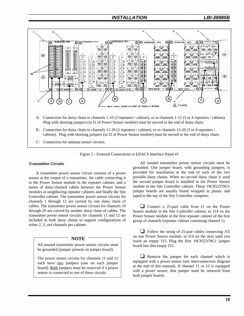
A: Connection for daisy chain to channels 1-10 (2 repeaters / cabinet), or to channels 1-12 (3 or 4 repeaters / cabinet).Plug with shorting jumpers (in J1 of Power Sensor module) must be moved to the end of daisy chain.
B: Connection for daisy chain to channels 11-20 (2 repeaters / cabinet), or to channels 13-20 (3 or 4 repeaters /cabinet). Plug with shorting jumpers (in J2 of Power Sensor module) must be moved to the end of daisy chain.
C: Connection for antenna sensor circuits.
Figure 2 - External Connections to EDACS Interface Panel #1
Transmitter Circuits
A transmitter power sensor circuit consists of a powersensor at the output of a transmitter, the cable connecting itto the Power Sensor module in the repeater cabinet, and aseries of daisy-chained cables between the Power Sensormodules in neighboring repeater cabinets and finally the SiteController cabinet. The transmitter power sensor circuits forchannels 1 through 12 are carried by one daisy chain ofcables. The transmitter power sensor circuits for channels 10through 20 are carried by another daisy chain of cables. Thetransmitter power sensor circuits for channels 11 and 12 areincluded in both daisy chains to support configurations ofeither 2, 3, or4 channels per cabinet.
All unused transmitter power sensor circuits mustbe grounded (jumper present on jumper board).
The power sensor circuits for channels 11 and 12each have two jumpers (one on each jumperboard). Both jumpers must be removed if a powersensor is connected to one of these circuits.
NOTE
All unused transmitter power sensor circuits must begrounded. One jumper board, with grounding jumpers, isprovided for installation at the end of each of the twopossible daisy chains. When no second daisy chain is usedthe second jumper board is installed in the Power Sensormodule in the Site Controller cabinet. These 19C852379G1jumper boards are usually found wrapped in plastic andtaped to the top of the Site Controller computer.
❏ Connect a 25-pair cable from J1 on the PowerSensor module in the Site Controller cabinet, to J14 on thePower Sensor module in the first repeater cabinet of the firstgroup of channels (repeater cabinet containing channel 1).
❏ Follow the string of 25-pair cables connecting J15on one Power Sensor module, to J14 on the next until youreach an empty J15. Plug the first 19C852379G1 jumperboard into this empty J15.
❏ Remove the jumper for each channel which isequipped with a power sensor (see interconnection diagramat the end of this manual). If channel 11 or 12 is equippedwith a power sensor, that jumper must be removed fromboth jumper boards.

LBI-38985B INSTALLATION
20
❏ Connect a 25-pair cable from J2 on the PowerSensor module in the Site Controller cabinet, to J14 on thePower Sensor module in the first repeater cabinet of thesecond group of channels (repeater cabinet containingchannel 11 or 13).
❏ Follow the string of 25-pair cables connecting J15on one Power Sensor module, to J14 on the next until youreach an empty J15. Plug the second 19C852379G1 jumperboard into this empty J15 (or into J2 on the Power Sensormodule in the Site Controller cabinet if there was no secondgroup of channels).
❏ Remove the jumper for each channel which isequipped with a power sensor (see interconnection diagramat the end of this manual). If channel 11 or 12 is equippedwith a power sensor, that jumper must be removed fromboth jumper boards.
Antenna Circuits
An antenna power sensor circuit consists of a powersensor at the input to a transmit antenna in that antenna’s RFcabinet and the cable connecting it directly to the PowerSensor module in the Site Controller cabinet. Both forwardand reflected antenna power sensor circuits for each of twopossible antennas share the same connector on the PowerSensor module in the Site Controller cabinet. All unusedantenna power sensor circuits must be grounded. No jumperboard is provided for this purpose, as was the case for thetransmitter power sensor circuits.
All unused antenna power sensor circuits must begrounded.
NOTE
❏ Plug the 19C852677P3 antenna power sensor cableinto J9 on the Power Sensor module. Run the branch of thecable containing the power sensor circuits for antenna #1(end of cable marked “1”) to the RF cabinet for antenna #1and plug the two phono plugs into the power sensor at theinput to the coax to antenna #1. The phono plug withblue/white wires is for forward power; the phono plug withorange/white wires is for reflected power.
❏ Run the branch of the cable containing the powersensor circuits for antenna #2 (end of cable marked “2”) tothe RF cabinet for antenna #2 and plug the two phono plugsinto the power sensor at the input to the coax to antenna #2.The phono plug with blue/white wires is for forward power;the phono plug with orange/white wires is for reflected
power. If the antenna power sensor circuits for antenna #2are not connected to a power sensor, they must be grounded(shorted). To ground the unused power sensor circuits forantenna #2, make up two shorted phono jacks and plug thetwo unused phono plugs into them.
“RIC AUDIO” Modules
If the EDACS Site Controller is equipped with aRIC/LIC Local Telephone Interconnect, the upper interfacepanel is equipped with two RIC AUDIO modules. Thesemodules provide the connection point for telephoneinterconnect audio circuits between each RIC (in a repeatercabinet) and the LIX/LIC Shelf (in the Site Controllercabinet). See Interconnection Diagram 9 or InterconnectionDiagram 10 at the end of this manual.
❏ Connect a 25-pair daisy-chain cable from J14 orJ15 (both are equal) on the “RIC AUDIO” module in thefirst EDACS Repeater cabinet for the 1st group of channels,to J14 or J15 (both are equal) on the “RIC AUDIO 1-12”module in the Site Controller cabinet.
❏ If the EDACS Trunked site is large enough to havea 2nd group of channels, connect a 25-pair daisy-chain cablefrom J14 or J15 (both are equal) on the “RIC AUDIO”module in the first EDACS Repeater cabinet for the 2ndgroup of channels, to J14 or J15 (both are equal) on the“RIC AUDIO 13-20” module in the Site Controller cabinet.
“GETC DATA” Modules
The upper interface panel is equipped with two GETCDATA modules which provide the connection point for thedata links between each Station GETC (in a repeatercabinet) and the Site Controller. See InterconnectionDiagram 6 at the end of this manual.
❏ Connect a 25-pair daisy-chain cable from J14 orJ15 (both are equal) on the “GETC DATA” module in thefirst EDACS Repeater cabinet for the 1st group of channels,to J14 on the left-hand “GETC DATA” module in the SiteController cabinet.
❏ If the EDACS Trunked site is large enough to havea 2nd group of channels, connect a 25-pair daisy-chain cablefrom J14 or J15 (both are equal) on the “GETC DATA”module in the first EDACS Repeater cabinet for the 2ndgroup of channels, to J14 on the right-hand “GETC DATA”module in the Site Controller cabinet.

INSTALLATION LBI-38985 B
21
“SERIAL MODULE” Module
The upper interface panel is equipped with a “SERIALMODULE” which provides the connection point for thefollowing signal lines:
• Backup Serial Line and Frame Sync Line betweenall Station GETCs (in a repeater cabinet) and theDownlink (and Redundant Downlink) GETC
• GETC Reset Line and Failsoft Status Line betweenall Station GETCs (in a repeater cabinet) and the ResetUnit for the Guardog option
• Serial data line between all RICs (in a repeatercabinet) and the Site Controller
The daisy chain from the first group of EDACSRepeater cabinets connects to J1 or J2; the second group toJ1 or J2. See Interconnection Diagram 8 (DownlinkGETCs), Interconnection Diagram 9 or InterconnectionDiagram 10 (RIC/LIC Interconnect), and InterconnectionDiagram 14 (Guardog) at the end of this manual.
❏ Connect a 15-conductor daisy-chain cable from J1or J2 (both are equal) on the “SERIAL MODULE” modulein the first EDACS Repeater cabinet for the 1st group ofchannels, to J1 or J2 (both are equal) on the “SERIALMODULE” module in the Site Controller cabinet.
❏ If the EDACS Trunked site is large enough to havea 2nd group of channels, connect a 15-conductor daisy-chaincable from J1 or J2 (both are equal) on the “SERIALMODULE” module in the first EDACS Repeater cabinet forthe 2nd group of channels, to J1 or J2 (both are equal) onthe “SERIAL MODULE” module in the Site Controllercabinet.
INTERFACE PANEL #2
The EDACS Site Controller is equipped with twoEDACS Interface Panels mounted in the back of the cabinetnear the top. The lower panel is referred to as EDACSInterface Panel #2 (part number 19D904009G13) and isshown in Figure 3.
A: Connection for Downlink and Redundant Downlink to CEC/IMC.
B: Connection for telephone lines # 1-16 (used for RIC/LIC Interconnect only).
C: Connection for telephone lines # 17-32 (used for RIC/LIC Interconnect only).
Figure 3 - External Connections to EDACS Interface Panel #2

LBI-38985B INSTALLATION
22
“DOWNLINK DATA” Module
The lower interface panel is equipped with a“DOWNLINK DATA” module which provides theconnection points between the Downlink and RedundantDownlink to the Console Electronics Controller (CEC) orIntegrated Multisite and Console Controller (IMC), and theBackup Serial Line (BSL) during Failsoft Trunking or theSite Controller during Full-Featured Trunking. SeeInterconnection Diagram 8 at the end of this manual orTable 1 for pin identification.
Table 1 - Downlink Connection Pin Identification
J14 PIN # DATA DIRECTION DATA CIRCUIT
261
Outgoing(To CEC/IMC)
MainDownlink
272
Incoming(From CEC/IMC)
MainDownlink
283
Outgoing(To CEC/IMC)
RedundantDownlink
294
Incoming(From CEC/IMC)
RedundantDownlink
❏ If the EDACS Site Controller is to be connected toa Console Electronics Controller (CEC) or IntegratedMultisite and Console Controller (IMC), connect a 25-pairdaisy-chain cable from J14 or J15 (both are equal) on the“DOWNLINK DATA” module to the protected punch-blockfor the Downlink and optional Redundant Downlink.
All telephone lines (or equivalent circuits) mustpass through protected punch blocks (orequivalent protection) before being connected tothe EDACS Interface Panel.
CAUTION
“PHONE LINE” Modules
If the EDACS Site Controller is equipped with aRIC/LIC Local Telephone Interconnect, the lower interfacepanel is equipped with two PHONE LINE modules. Thesemodules provide the connection point for the audio circuitsbetween the local telephone lines and the LIX/LIC Shelf.Telephone lines 1-16 are connected to J14 or J15 on the"PHONE LINE 1-16" module, and telephone lines 17-32 areconnected to J14 or J15 on the "PHONE LINE 17-20"module. See Interconnection Diagram 9 or Interconnection
Diagram 10 at the end of this manual or Table 2 for pinidentification.
Table 2 - Telephone Line Connection Pin Identification
J14 TELEPHONE LINE #
PIN#
WIRE PHONE LINE 1-16MODULE
PHONE LINE 17-32MODULE
261
TipRing 1 17
272
TipRing 2 18
283
TipRing 3 19
294
TipRing 4 20
305
TipRing 5 21
316
TipRing 6 22
327
TipRing 7 23
338
TipRing 8 24
349
TipRing 9 25
3510
TipRing 10 26
3611
TipRing 11 27
3712
TipRing 12 28
3813
TipRing 13 29
3914
TipRing 14 30
4015
TipRing 15 31
4116
TipRing 16 32
❏ Connect a 25-pair daisy-chain cable from J14 orJ15 (both are equal) on the “PHONE LINE 1-16” module, tothe protected punch-block for those local subscriber lines.
INSTALLATION LBI-38985 B
23
❏ If more than 16 local subscriber lines are to beconnected to the RIC/LIC Local Telephone Interconnect,connect a 25-pair daisy-chain cable from J14 or J15 (bothare equal) on the “PHONE LINE 17-32” module, to theprotected punch-block for those local subscriber lines.
All telephone lines (or equivalent circuits) mustpass through protected punch blocks (orequivalent protection) before being connected tothe EDACS Interface Panel.
CAUTION
DIRECT CONNECTIONS
Some external connections to the Site Controller cabinetbypass the EDACS Interface Panels and connect directly toa specific piece of equipment within the cabinet. Directconnections that may be required are shown in Figure 4.
When installing direct connections, use cable ties tosecure the cables to the side rails of the cabinet. Be carefulto route the cables so that they do not block access to anyequipment or mounting screws.
Avoid routing any cables near the sharp end ofmounting screws, and route the cables so thatmounting screws can be removed and re-installed without damaging the cables.
CAUTION
ELI Local Telephone Interconnect
If the system is equipped with the ELI Local TelephoneInterconnect, a RIC Data Link cable and LIC Data Linkcable are connected directly between the Master GTI unit (ina repeater cabinet) and the Site Controller.
❏ Connect the RIC Data Link cable from J4 (left-hand 6-pin modular jack) on the back of the Master GTIunit, to Port 30 (RIC) on the back of the Site Controller.
❏ Connect the LIC Data Link cable from J5 (right-hand 6-pin modular jack) on the back of the Master GTIunit, to Port 31 (LIC) on the back of the Site Controller.
J4 J5
J3
Control Outputs C1-C8
Alarm Inputs A1-A16
Alarm Inputs A17-A32
Antenna
Data Link with Modem
External Alarm OutputGuardog
GuardogTelephone Line
ELI Local Telephone
RIC Data Link
ELI Local Telephone
LIC Data Link
Alarm and Control Unit
Alarm and Control Unit
Alarm and Control Unit
Orion Test Unit
System Manager
(Add to existing plug)
(Add to J2-8 inside)Automatic Reset DisableGuardog ExternalJ4J5J6
31 30
System ManagerData Link
0
Interconnect
Interconnect
without Modem
J8
Figure 4 - Direct Connections (Rear View)
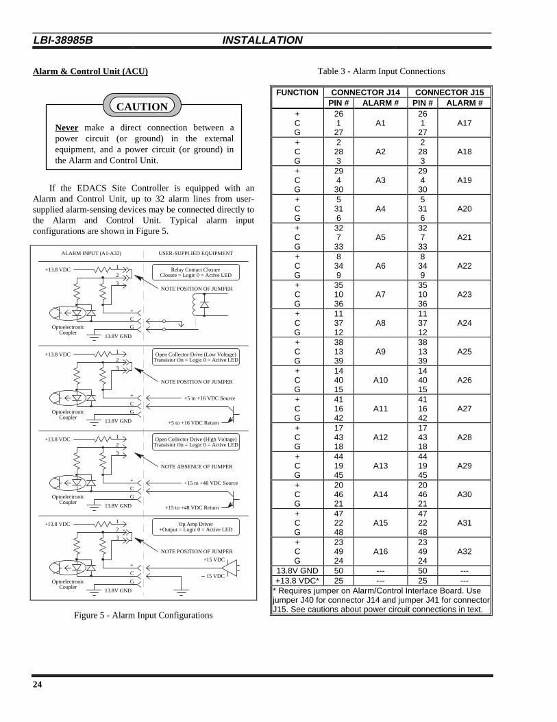
LBI-38985B INSTALLATION
24
Alarm & Control Unit (ACU)
Never make a direct connection between apower circuit (or ground) in the externalequipment, and a power circuit (or ground) inthe Alarm and Control Unit.
CAUTION
If the EDACS Site Controller is equipped with anAlarm and Control Unit, up to 32 alarm lines from user-supplied alarm-sensing devices may be connected directly tothe Alarm and Control Unit. Typical alarm inputconfigurations are shown in Figure 5.
USER-SUPPLIED EQUIPMENTALARM INPUT (A1-A32)
+13.8 VDC Relay Contact ClosureClosure = Logic 0 = Active LED
+
C
G
1
2
3
+13.8 VDC Open Collector Drive (Low Voltage)Transistor On = Logic 0 = Active LED
+
C
G
1
2
3
OptoelectronicCoupler
OptoelectronicCoupler
+5 to +16 VDC Return
+5 to +16 VDC Source
+13.8 VDC Open Collector Drive (High Voltage)Transistor On = Logic 0 = Active LED
+
C
G
1
2
3
OptoelectronicCoupler
+15 to +48 VDC Return
+15 to +48 VDC Source
NOTE POSITION OF JUMPER
NOTE ABSENCE OF JUMPER
+13.8 VDC Op Amp Driver+Output = Logic 0 = Active LED
+
C
G
1
2
3
OptoelectronicCoupler
NOTE POSITION OF JUMPER
15 VDC
+15 VDC
NOTE POSITION OF JUMPER
13.8V GND
13.8V GND
13.8V GND
13.8V GND
Figure 5 - Alarm Input Configurations
Table 3 - Alarm Input Connections
FUNCTION CONNECTOR J14 CONNECTOR J15PIN # ALARM # PIN # ALARM #
+CG
261
27A1
261
27A17
+CG
2283
A22
283
A18
+CG
294
30A3
294
30A19
+CG
5316
A45
316
A20
+CG
327
33A5
327
33A21
+CG
8349
A68
349
A22
+CG
351036
A7351036
A23
+CG
113712
A8113712
A24
+CG
381339
A9381339
A25
+CG
144015
A10144015
A26
+CG
411642
A11411642
A27
+CG
174318
A12174318
A28
+CG
441945
A13441945
A29
+CG
204621
A14204621
A30
+CG
472248
A15472248
A31
+CG
234924
A16234924
A32
13.8V GND 50 --- 50 ---+13.8 VDC* 25 --- 25 ---
* Requires jumper on Alarm/Control Interface Board. Usejumper J40 for connector J14 and jumper J41 for connectorJ15. See cautions about power circuit connections in text.

INSTALLATION LBI-38985 B
25
All external connections to equipment locatedoutside the room housing the EDACS SiteController must pass through protected punchblocks (or equivalent protection) before beingconnected to the Alarm and Control Unit.
CAUTION
❏ Connect alarm lines to J4 and J5 on the back of theAlarm and Control Unit using standard 25-pair Telco-typeconnectors. Pin-out information is shown in Table 3, andInterconnection Diagram 13 at the end of this manual.
If the EDACS Site Controller is equipped with anAlarm and Control Unit, up to 8 control lines may also beconnected directly to user-supplied devices to be remotelycontrolled. Typical control line configurations are shown inFigure 6.
USER-SUPPLIED EQUIPMENTCONTROL OUTPUT (C1-C8)
+V
User's LoadTo Be Controlled
Control Output SwitchesUser's Load
User's RelayControl Output Switches
N.O.
COM
N.C.
N.O.
COM
N.C.
13.8V GND
+13.8 VDC+13.8 VDC
+V
User's LoadTo Be Controlled
Figure 6 - Control Output Configurations
All external connections to equipment locatedoutside the room housing the EDACS SiteController must pass through protected punchblocks (or equivalent protection) before beingconnected to the Alarm and Control Unit.
CAUTION
❏ Connect Control lines to J3 on the back of theAlarm and Control Unit using a standard 25-pair Telco-typeconnector. Pin-out information is shown in Table 4, andInterconnection Diagram 13 at the end of this manual.
Table 4 - Control Output Connections
FUNCTION CONNECTOR J3
PIN # CONTROL # PIN # CONTROL #
N.O.COMN.C.
26127
C132733
C5
N.O.COMN.C.
2283
C28349
C6
N.O.COMN.C.
29430
C3351036
C7
N.O.COMN.C.
5316
C4113712
C8
+5 VDC+5 VDC5V GND5V GND
+13.8 VDC+13.8 VDC13.8V GND13.8V GND
1338143915401641
+5 VDC requires jumper P38 onAlarm/Control Interface Board.
+13.8 VDC requires jumper P39on Alarm/Control Interface Board.
See cautions in text aboutconnections to power circuits.
Test Unit (TU)
If the EDACS Site Controller is equipped with a TestUnit (TU), a magnetic-base antenna is connected directly tothe TU Shelf.
❏ Connect the TU antenna’s cable to the antennaconnector on the back of the TU Shelf. If it is necessary tomount the TU antenna outside of the building, the antennacable must be lightning protected where it enters theequipment room.
Guardog
If the EDACS Site Controller is equipped with theGuardog option, the following direct connections may berequired to the Modem / Reset Unit chassis:
• Telephone Line (or equivalent circuit) - forremotely initiating a reset, disabling automaticreset, and checking status
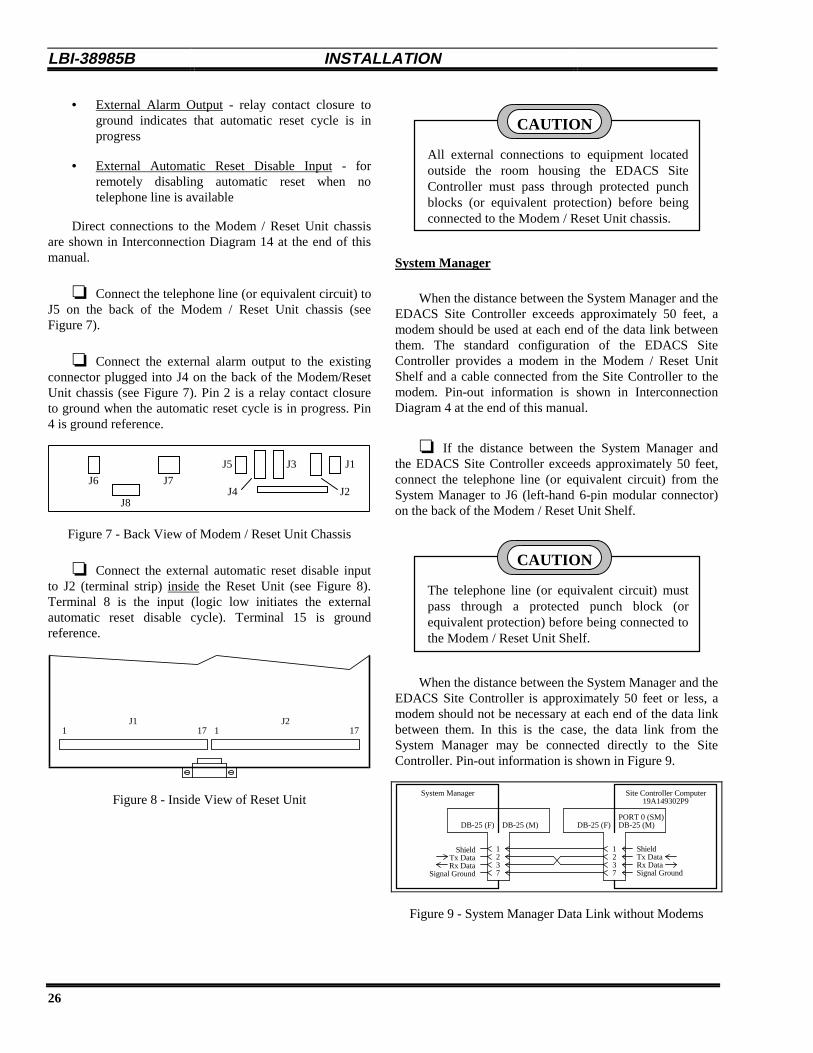
LBI-38985B INSTALLATION
26
• External Alarm Output - relay contact closure toground indicates that automatic reset cycle is inprogress
• External Automatic Reset Disable Input - forremotely disabling automatic reset when notelephone line is available
Direct connections to the Modem / Reset Unit chassisare shown in Interconnection Diagram 14 at the end of thismanual.
❏ Connect the telephone line (or equivalent circuit) toJ5 on the back of the Modem / Reset Unit chassis (seeFigure 7).
❏ Connect the external alarm output to the existingconnector plugged into J4 on the back of the Modem/ResetUnit chassis (see Figure 7). Pin 2 is a relay contact closureto ground when the automatic reset cycle is in progress. Pin4 is ground reference.
J6
J8
J7
J5
J4
J3
J2
J1
Figure 7 - Back View of Modem / Reset Unit Chassis
❏ Connect the external automatic reset disable inputto J2 (terminal strip) inside the Reset Unit (see Figure 8).Terminal 8 is the input (logic low initiates the externalautomatic reset disable cycle). Terminal 15 is groundreference.
1 17 1 17J1 J2
Figure 8 - Inside View of Reset Unit
All external connections to equipment locatedoutside the room housing the EDACS SiteController must pass through protected punchblocks (or equivalent protection) before beingconnected to the Modem / Reset Unit chassis.
CAUTION
System Manager
When the distance between the System Manager and theEDACS Site Controller exceeds approximately 50 feet, amodem should be used at each end of the data link betweenthem. The standard configuration of the EDACS SiteController provides a modem in the Modem / Reset UnitShelf and a cable connected from the Site Controller to themodem. Pin-out information is shown in InterconnectionDiagram 4 at the end of this manual.
❏ If the distance between the System Manager andthe EDACS Site Controller exceeds approximately 50 feet,connect the telephone line (or equivalent circuit) from theSystem Manager to J6 (left-hand 6-pin modular connector)on the back of the Modem / Reset Unit Shelf.
The telephone line (or equivalent circuit) mustpass through a protected punch block (orequivalent protection) before being connected tothe Modem / Reset Unit Shelf.
CAUTION
When the distance between the System Manager and theEDACS Site Controller is approximately 50 feet or less, amodem should not be necessary at each end of the data linkbetween them. In this is the case, the data link from theSystem Manager may be connected directly to the SiteController. Pin-out information is shown in Figure 9.
System Manager Site Controller Computer19A149302P9
1237
ShieldTx DataRx DataSignal Ground
PORT 0 (SM)
Shield
Rx DataTx Data
Signal Ground
DB-25 (F) DB-25 (M)
1237
DB-25 (F) DB-25 (M)
Figure 9 - System Manager Data Link without Modems
INSTALLATION LBI-38985 B
27
❏ If the distance between the System Manager andthe EDACS Site Controller is approximately 50 feet or less,connect the telephone line (or equivalent circuit) from theSystem Manager directly to Port 0 (SM) on the back of theSite Controller (see Figure 9). (You will need to disconnectthe cable from the System Manager Modem first, if a SystemManager Modem was supplied.)
INITIAL POWER-UP
❏ Turn off the following individual pieces ofequipment in the Site Controller cabinet:
• DC power supply
• Site Controller
• Power Monitor Unit
• Test Unit radio
❏ Turn on the AC power circuit breaker for the SiteController cabinet. Verify that the fan at the top of thecabinet, the UPS, and the System Manager Modem are on.
❏ Turn on the DC power supply. Verify that theDownlink GETC, Redundant Downlink GETC, Alarm andControl Unit, and Reset Unit (Guardog) are on.
❏ Turn on the Site Controller. Verify that the SiteController is on.
❏ Turn on the Power Monitor Unit. Verify that thePower Monitor Unit is on.
❏ Turn on the Test Unit radio. Verify that the TestUnit radio is on.

LBI-38985B FULL-FEATURED TRUNKING
28
FULL-FEATURED TRUNKING
Full-Featured Trunking refers to trunking under thedirection of the Site Controller with a full set of standardfeatures. To determine if a system is operating in Full-Featured Trunking, look at the L1 indicator on the front ofthe Station or Downlink GETCs. The L1 indicator will notbe lit when operating in Full-Featured Trunking.
The operation of the Site Controller depends upon theversion of the Application Software installed. Except wherenoted otherwise, the operation described in this section is forApplication Software identified by part number344A3265G7. See the Software Replacement heading in theMaintenance section of this manual for information on thelocation and identification of the Application Software.
SITE CONTROLLER STARTUP
Initialization
Whenever the Site Controller is powered up or reset, theSite Controller initializes its working memory, loads theApplication Software from its set of 14 ApplicationSoftware PROMs, loads the initial set of parameter valuesfrom its set of 2 Personality PROMs, and starts running theApplication Software. The initial set of parameter values inthe Site Controller’s working memory is referred to as theInitial Configuration.
Request for Site Database
Once the Application Software is running, the SiteController requests the latest Site Database from the SystemManager. When the Site Database is received from theSystem Manager, some parameter values may change in theworking memory. However, the initial parameter values inthe Site Controller’s Personality PROMs remain unchanged.The modified set of parameter values in the Site Controller’sworking memory is referred to as the Active Configuration.
The Active Configuration may be changed as often asneeded by partial or complete Site Database transfers fromthe System Manager. However, some parameter values (suchas the Site ID) cannot be reconfigured by the SystemManager. If any change needs to be made for any parametervalue in the Initial Configuration, the change must be madein the set of 2 Personality PROMs.
Switch Operational Mode of Site
If the Site Controller is powered up and becomesoperational (allow 90 seconds) before the Station GETCsare powered up and become operational (allow 15 seconds),the site will become operational in the Full-FeaturedTrunking mode. If however, the Site Controller becomesoperational after the Station GETCs become operational, thesite will become operational in the Failsoft Trunking mode.
To switch, reset the Control Channel GETC (press S4on the front edge of the GETC Logic Board). If this does notbring the site out of Failsoft, then try resetting all StationGETCs (press S4 on the front edge of the GETC LogicBoard) within a few seconds of each other (last one must bestarted before the first one completes its reset). Analternative method is to turn off all Station GETCs (turn offeach repeater’s DC Power Supply) until all are off. Thenpower up one repeater at a time.
GETC COMMUNICATION
GETC Data Links
Each Station and Downlink GETC receives instructionsfrom the Site Controller via a separate GETC data link. TheGETC data links for the Downlink GETC and RedundantDownlink GETC connect directly to the Site Controller. TheGETC data links for the Station GETCs use GETC DATAinterface modules as the connection points between cabinets.
Frame Sync Line (FSL)
Each Working Channel and Downlink GETC receivessynchronization pulses from the Control Channel GETC viaa single FSL (Frame Sync Line) connected to all GETCs.These pulses tell each Downlink and Working ChannelGETC whether the Site Controller or the Control ChannelGETC is directing the EDACS trunking. The FSL uses theSERIAL interface module as the connection point withinand between cabinets.
CONTROL CHANNEL SELECTION
The Control Channel is the RF channel to which all userradios tune to receive or request directions for a trunkedcall. (The trunked call itself takes place on a WorkingChannel.) Only one RF channel can be a Control Channel ata time. To determine which RF channel is serving as theControl Channel, look at the L6 indicator on the front ofeach Station GETC. The L6 indicator on the Control

FULL-FEATURED TRUNKING LBI-38985 B
29
Channel GETC will remain lit continuously. (The L6indicator on a Working Channel GETC will only be lit whenassigned to a call.)
Startup
At startup, the Site Controller selects the ControlChannel as specified in its Initial Configuration (defaults tolowest RF channel allowed to be a Control Channel, whichshould be channel 2). The System Manager maysubsequently change which channels are allowed to be usedas a Control Channel, and move the Control Channel at willwithin the allowed channels.
Control Channel Failure
If the Control Channel GETC fails to respond to a SiteController poll or is failed by an alarm (such as from the TUor PMU), the Site Controller will select the next higherchannel number (of the available channels that are allowedto be Control Channels) to be the new Control Channel.When the original Control Channel is fixed and tested, theSite Controller will add the channel to its bitmap ofavailable Working and Control Channels, but leave theControl Channel where it is.
WORKING CHANNEL ASSIGNMENTS
A Working Channel is an EDACS Repeater channel towhich user radios can be assigned for a trunked call. AllEDACS Repeater channels, other than the Control Channel,are Working Channels.
Communication Modes
Working Channel assignments are based on theavailability of a channel that has been enabled to support therequested communication mode. A mask in the SiteController’s Personality is used to enable each channel forany combination of the following communication modes:
• RF (Normal Analog Voice) - EDACS Repeater isrequired for channel.
• Interconnect - Local Telephone Interconnectequipment is required for channel.
• Digital Voice - Station GETC to handle DigitalVoice is required for channel.
• Data - Station GETC to handle Data is required forchannel.
• Channel Test - No special equipment is requiredfor channel.
• Wide Area - Connections to network are requiredfor channel.
A similar mask may be reconfigured in the SiteDatabase (System Manager screen 10) and send to the SiteController (System Manager screen 20) to modify its ActiveConfiguration.
Call Sequence
When an EDACS mobile or portable radio is turned on,its receiver scans the channels of the system looking for theControl Channel. Once found, the radio synchronizes itselfwith and decodes the periodic control messages (every 30milliseconds). Once the field radio is synchronized with thecontrol message on the Control Channel, it is ready to placeor receive trunked calls. The following sequence of stepsdescribes the placing of a call:
1. The user of a field radio selects the communicationmode (normal analog voice, digital voice, data, etc.),call type (individual, group, emergency group,interconnect, or system all call), and the individual orgroup called. An individual call from a radio can be toanother radio, or can be a telephone interconnect call toa telephone number. (A telephone interconnect callfrom a telephone can be to an individual or group.) Theuser then pushes the Push-To-Talk (PTT) switch on theradio.
2. The radio transmits a call request message on theControl Channel. The message includes the radio'sidentification (LID), communication mode, call type,and the identification (LID or GID) of the calledradio(s).
3. The Control Channel GETC receives the call requestfrom the calling radio, translates it to Site Controllerprotocol, and sends a call/channel request message tothe Site Controller.
4. The Site Controller receives the message and checkswith its Active Configuration to see if the request ispermitted. (If it isn't permitted, the Site Controller sendsan appropriate system busy or call denied message tothe Control Channel GETC which in turn sends a properindication to the calling radio.)
5. If the call request is permitted, the Site Controllerchecks to see if a Working Channel is available. (If aWorking Channel is not currently available, the SiteController queues the call request and directs the
LBI-38985B FULL-FEATURED TRUNKING
30
Control Channel GETC to send a queued-call signal tothe calling radio. When the call request comes out ofqueue, continue to next step.) If queuing is disabled orotherwise not possible, the Site Controller generates asystem busy indication.
6. The Site Controller directs the Control Channel GETCto send the Working Channel assignment to the callingand called radios. The Site Controller also sendschannel assignments to the Downlink to supportmultisite and/or console operation. This channelassignment includes a hang time value for this call. Ahang time of zero indicates Transmission Trunking;non-zero indicates Message Trunking.
7. The calling and called radios receive the WorkingChannel assignment from the Control Channel GETCand tune to the assigned Working Channel.
8. A high speed handshake on the Working Channel withthe calling radio occurs.
9. After confirmation, the caller hears the "OK totransmit" prompt tone alerting the caller to begintalking.
10. Signaling on the assigned Working Channel tells thecalled radio(s) to unmute their speakers.
11. When the caller finishes talking, the caller releases thePTT switch, sending an unkey message to the assignedWorking Channel and all called radio(s). The SiteController receives either a call dropped (TransmissionTrunked call) or a call unkey (Message Trunked call).
12. With Transmission Trunking, the radios involved in thecall return to monitor the Control Channel. WithMessage Trunking, the radios stay on the WorkingChannel until hang time expiration or manual drop.
When the radio receives a message containing its LIDor GID, the radio responds to the Control Channel GETCand is given a Working Channel assignment. The radioswitches to the assigned Working Channel, exchangesinformation with the Working Channel GETC, and theWorking Channel GETC opens up the channel between thecalling radio and the called radio.
CALL VALIDATION
All call requests made to the site are checked by the SiteController to verify that the ID is valid at (permitted to use)the site. (Each GID or LID must have the sites for which it isvalid defined in the Site Database.)
CALL QUEUING
When all channels enabled for the requested grade ofservice (Analog Voice, Digital Voice, Data, and TelephoneInterconnect) are busy, the call is queued. When a channelenabled for the requested grade of service becomesavailable, queued call requests are filled first by prioritylevel and second by time in queue.
The Site Controller manages a separate queue for eachof the 4 grades of service. Within each queue, the SiteController manages 8 priority levels configurable by ID. Thehigher of the caller's or the callee's priority is used. Theseeight priority levels are defined for each ID for each gradeof service. The default priority level for each ID for eachgrade of service is the lowest priority level, but can bereconfigured in System Manager screen 11, panel 2 for anLID or screen 12, panel 2 for a GID. System all-calls alwayshave higher priority than any other call. Emergency callshave next highest priority. For these calls, the group priorityis used to determine the priority between two or moreemergency calls.
The Site Controller gives a recent user a slight edgewhen its call is queued (to help maintain the continuity of aconversation). The Site Controller increases the priority of acall request by half a level if the time between the last callrequest and the current call request is less than the RecentCall Queue Interval for the site. The Recent Call QueueInterval has a default value of 5 seconds, but can bereconfigured in System Manager screen 21, panel 2.
DOWNLINK SELECTION
A Downlink is a data link between the Station GETCsand Site Controller in a single EDACS system, and theCEC/IMC switch in an EDACS network. A DownlinkGETC is used as a data interface at the system end (anUplink GETC is used at the network end). A modem in theDownlink (and Uplink) GETC converts DC data signalsused by the system (and network) to/from voice-frequencysignals (for transmission over the Downlink).
Downlink selection is only an issue when a RedundantDownlink and its Redundant Downlink GETC is used tobackup the (main) Downlink and its Downlink GETC.Channel 26 is always Downlink enabled in the SiteController’s Active Configuration and is reserved for the(main) Downlink. Channel 25 must be Downlink enabled inthe Site Controller’s Active Configuration if the system isequipped with a Redundant Downlink. The RedundantDownlink may be enabled in the Site Database (SystemManager screen 10) and send to the Site Controller (SystemManager screen 20) to modify its Active Configuration.
FULL-FEATURED TRUNKING LBI-38985 B
31
Downlink selection is based on which channel numbershave been Downlink enabled in the Site Controller’s ActiveConfiguration and which Downlink is not failed. Assumingthat the (main) Downlink has not failed, the Site Controllerwill initially select the (main) Downlink GETC.
A Downlink will be failed for either of the followingreasons:
• Poll Failure - The Site Controller does not receive apole response message from the Downlink GETCfor a specific number of consecutive poll cycles.This number is specified in the Site Controller’sPersonality (normally is 2). Currently, the SystemManager sends a default value of 2 to the SiteController though, which cannot be reconfigured bythe System Manager.
• Link Failure - The modem in the Downlink GETCstops receiving information from the network end.
If the (main) Downlink is failed and the system isequipped with a functioning Redundant Downlink, the SiteController will select the Redundant Downlink. After the(main) Downlink GETC is fixed, the Site Controller will notswitch back to the (main) Downlink GETC, unless theRedundant Downlink fails or the Site Controller is poweredon or restarted.
SITE CONTROLLER FAILURE
If the Control Channel GETC stops receiving pollingmessages from the Site Controller, the Control ChannelGETC signals all Station GETCs via the FSL (Frame SyncLine) to switch their serial input from the individual datalinks (to the Site Controller) to the single BSL (BackupSerial Line) connecting all GETCs together. The ControlChannel GETC then directs the Working Channel GETCsvia the BSL. EDACS trunking, under the direction of theControl Channel GETC, is referred to as Failsoft Trunking.
SITE CONTROLLER RECOVERY
When the Site Controller resumes sending pollingmessages to the Station GETCs, the Station GETCs will beunaware of the polling messages on their individual datalinks to the Site Controller, because they have switched theirserial input to the BSL. To force each Station GETC to
switch its serial input from the BSL to its individual datalink to the Site Controller, reset the Control Channel GETC.The Control Channel GETC will then tell the other StationGETCs (via the FSL) to switch from the BSL to the theirindividual data links to the Site Controller.
When a Station GETC is reset or powered up, it firstlooks at the FSL to determine if it should switch its serialinput to either the BSL or its individual data link to the SiteController. If the Control Channel GETC is in the SiteController mode, then the Station GETC will switch to theSite Controller mode. If the Control Channel GETC is in theFailsoft mode, then the Station GETC will switch to theFailsoft mode.
When a Station GETC is reset or powered up, itswitches its serial input to its individual data link to the SiteController. If it sees polling from the Site Controller, it willresume responding to polls. The first Station GETC (that isallowed to be a Control Channel) to resume responding topolling messages from the Site Controller will be selected bythe Site Controller to be the Control Channel GETC. Eachsubsequent Station GETC that resumes responding topolling messages from the Site Controller will be a WorkingChannel GETC.
If the whole site is powered up together after aprolonged power outage (one long enough to discharge thebattery in the Uninterruptible Power Supply), the site willcome up in the Failsoft Trunking mode of operation. This isbecause it takes much longer for the Site Controller toinitialize itself than for the Station GETCs. Therefore, at thetime each Station GETC is looking for polling messages onits individual data link to the Site Controller, the SiteController hasn’t finished the initialization and isn’t sendingany polling messages to the Station GETCs. The StationGETCs, seeing no polling messages, assume the SiteController has failed and switch to the Failsoft Trunkingmode of operation.
If the whole site is powered up together after a shortpower outage (one short enough not to discharge the batteryin the Uninterruptible Power Supply), the site will come upin the Full-Featured Trunking mode of operation. This isbecause the Site Controller remained powered up by theUninterruptible Power Supply and did not have to beinitialized. Therefore, when the Station GETCs finishedtheir initialization, they were able to see and respond to thepolling messages from the Site Controller.

LBI-38985B SYSTEM MANAGER
32
SYSTEM MANAGER
DATA LINK
If a System Manager is to be used with the SiteController, the System Manager must be connected to theSite Controller by a data link. If the distance between theSystem Manager and the Site Controller exceedsapproximately 50 feet, a modem is needed at each locationto translate the DC logic levels from the RS-232 interface toaudio frequencies and back to DC logic levels. The modemthat is located at the Site Controller end is identified as theSystem Manager Modem. See the manual for the SystemManager Modem (number is listed in the Introduction of thismanual) for set-up information.
Baud Rate
The baud rate of the Site Controller’s data interface forthe data link to the System Manager must be specified in theSite Controller’s Personality. If not specified by thecustomer in time for factory assembly, 9600 BPS isspecified. Other selections are 300, 1200, 2400, 4800, and19200 BPS. Later changes will require the ordering of a newset of Personality PROMs from the factory (not fieldprogrammable).
Data Link
The type of data link used to connect the SystemManager to the Site Controller must be specified in the SiteController’s Personality. If not specified by the customer intime for factory assembly, the hardwire connection (metallicconductors suitable for connecting RS-232 interface to RS-232 interface directly without modems) is specified. Otherselections are dial-up and dedicated telephone lines. Laterchanges will require the ordering of a new set of PersonalityPROMs from the factory (not field programmable).
PARAMETERS
Some parameters in the Site Controller’s Personality arenot included in the System Manager’s databases, andtherefore cannot be reconfigured through the SystemManager. Some parameters in the System Manager’sdatabases are not included in the Site Controller’sPersonality, and therefore are only configurable through theSystem Manager.
After a parameter is reconfigured in one of the SystemManager’s databases, the reconfigured database can be sentto the site where it will update the Site Controller’s Active
Configuration. Whenever the Site Controller is powered upor reset, it will request a download from the SystemManager of the latest databases that apply to the site. A fewparameters, despite being displayed on a System Managerscreen, are for information only and cannot be reconfiguredthrough the System Manager. (See the System Managerinstruction manual for details.)
Values for the following trunking parameters areprogrammed into the Personality PROMs for the SiteController in the factory. If the Site Controller is connectedto a System Manager, their values can be reconfigured in theSite Controller’s Active Configuration through the SystemManager. If the Site Controller is not connected to a SystemManager, their values can only be reconfigured by orderinga new set of Personality PROMs from the factory. The SiteController default values are used if not specified otherwiseby the customer.
• Which channel is the initial Control Channel? TheSite Controller and System Manager defaults arechannel 2.
• RF (External Device Definition) - Which channelsare equipped to handle RF calls? The SiteController default is Y (enabled) for channels 1through 20 and N (disabled) for channels 21through 26. The System Manager default is N(disabled) for channels 1 through 24.
• Allowed CC (External Device Definition) - Whichchannels are allowed to be a Control Channel? TheSite Controller default is N (disabled) for channels1 and 21 through 26, and Y (enabled) for channels2 through 20. The System Manager default is N(disabled) for channels 1 through 24.
• Downlink (External Device Definition) - Whichchannels are used for a Downlink? The SiteController default is N (disabled) for channels 1through 20 and Y (enabled) for channels 21through 26. The System Manager default is N(disabled) for channels 1 through 25 and Y(enabled) for channel 26. (Channel 26 is alwaysused for the primary Downlink and channel 25 isusually used for the first redundant Downlink.)
• Rotate Assignments (External Device Definition) -Should Working Channels be assigned in rotation?Choices are Y (enable) and N (disable). The SiteController and System Manager default is Y(enable).
• Wide Area (External Device Definition) - ShouldWorking Channels be assigned in ascending
SYSTEM MANAGER LBI-38985 B
33
rotation? Choices are Y (ascending) and N(descending). The Site Controller and SystemManager default is Y (ascending rotation).
• Assign Non-Adjacent Chan (External DeviceDefinition) - Should Working Channels be assignedusing the non-adjacent channel assignmentalgorithm? The Site Controller and SystemManager defaults are N (disabled). This isnormally enabled for 900 MHz systems.
• Digital Voice (External Device Definition) - Whichchannels are equipped to handle digital voice calls?The Site Controller default is Y (enabled) forchannels 1 through 20 and N (disabled) forchannels 21 through 26. The System Managerdefault is N (disabled) for channels 1 through 24.
• Interconnect (External Device Definition) - Whichchannels are equipped to handle Local Interconnectcalls? The Site Controller default is Y (enabled)for channels 1 through 20. The System Managerdefault is N (disabled) for channels 1 through 24.
• Data (External Device Definition) - Whichchannels are equipped to handle data calls? TheSite Controller default is Y (enabled) for channels1 through 20 and N (disabled) for channels 21through 26. The System Manager default is N(disabled) for channels 1 through 24.
• Channel Test (External Device Definition) - Whichchannels are assigned for Channel Test? The SiteController default is N (disabled for channels 1through 26. The System Manager default is N(disabled) for channels 1 through 24.
• Wide Area (External Device Definition) - Whichchannels are equipped to handle Wide Area calls(requires connections to an IMC switch)? The SiteController default is Y (enabled) for channels 1through 20 and N (disabled) for channels 21through 26. The System Manager default is N(disabled) for channels 1 through 24.
• Wide Area Enable (Unit Identification) - WhichLIDs are permitted to place and receive Wide Areacalls? Choices are Y (enable) and N (disable). TheSite Controller and System Manager defaults are N(disable) for each LID.
• Wide Area Enable (Group Identification) - WhichGIDs are permitted to receive Wide Area calls?Choices are Y (enable) and N (disable). The Site
Controller and System Manager defaults are N(disable) for each GID.
• Hang Time (Unit Identification) - What is the hangtime between unkey and channel drop for all calls(except interconnect and emergency) to this LID?Range is 0 to 255 seconds. The Site Controller andSystem Manager defaults are 0 seconds for eachLID. (Note that operation with a hang time of 0seconds results in transmission trunking. To allowmessage trunking, the hang time must bereconfigured to more than 0 seconds.)
• Hang Time (Group Identification) - What is thehang time between unkey and channel drop for allcalls (except interconnect and emergency) to thisGID? Range is 0 to 255 seconds. The SiteController and System Manager defaults are 0seconds for each GID. (Note that operation with ahang time of 0 seconds results in transmissiontrunking. To allow message trunking, the hang timemust be reconfigured to more than 0 seconds.)
• Voice (Unit Identification) - What is the queuepriority for normal voice calls to this LID? Rangeis 0 (low) to 7 (high). The Site Controller default is3 for each LID. The System Manager default is 0for each LID.
• Voice (Group Identification) - What is the queuepriority for normal voice calls to this GID? Rangeis 0 (low) to 7 (high). The Site Controller default is3 for each GID. The System Manager default is 0for each GID.
• Digital Voice (Unit Identification) - What is thequeue priority for digital voice calls to this LID?Range is 0 (low) to 7 (high). The Site Controllerdefault is 3 for each LID. The System Managerdefault is 0 for each LID.
• Digital Voice (Group Identification) - What is thequeue priority for digital voice calls to this GID?Range is 0 (low) to 7 (high). The Site Controllerdefault is 3 for each GID. The System Managerdefault is 0 for each GID.
• Data (Unit Identification) - What is the queuepriority for data calls to this LID? Range is 0 (low)to 7 (high). The Site Controller default is 3 foreach LID. The System Manager default is 0 foreach LID.
• Data (Group Identification) - What is the queuepriority for data calls to this GID? Range is 0 (low)
LBI-38985B SYSTEM MANAGER
34
to 7 (high). The Site Controller default is 3 foreach GID. The System Manager default is 0 foreach GID.
• Recent Call Queue Int (External Device Definition)- What is the maximum allowable time between callrequests to still qualify for the recent call priorityincrement? Range is 0 to 30 seconds. The SiteController and System Manager defaults are 5seconds.
• Morse Code Id Interval (External DeviceDefinition) - What is the time interval betweenconsecutive Morse code ID transmissions? Rangeis 0 to 30 minutes. The Site Controller and SystemManager defaults are 30 minutes.
• Scramble Data Call Int (External DeviceDefinition) - What is the time between successivetransmissions in a scrambled data call (call consistsof a series of transmissions on randomly-selectedchannels to discourage unauthorized monitoring)?Range is 0 (feature disabled) to 32,767 seconds(about 9.1 hours). The Site Controller default is 0seconds. The System Manager default is 5seconds.
• Activity Dump Threshold (External DeviceDefinition) - What is the Activity Dump Threshold(the number of activity records that need toaccumulate in the activity file in order to trigger anautomatic download to the System Manager)?Range is 0 to 16,383 activity records. The SiteController and System Manager defaults are 1000activity records.
Values for the following trunking parameters are notprogrammed into the Personality PROMs for the SiteController. If the Site Controller is connected to a SystemManager, their values can be reconfigured in the SiteController’s Active Configuration through the SystemManager. If the Site Controller is not connected to a SystemManager, their values cannot be reconfigured from the SiteController defaults.
• Message Conv Limit (External Device Definition) -What is the time limit for message-trunked calls(same channel for each transmission)? Range is 10to 2550 seconds (about 44 minutes). The SiteController and System Manager defaults are 5minutes.
• Transmission Conv Limit (External DeviceDefinition) - What is the time limit fortransmission-trunked calls (new channel for each
transmission)? Range is 10 to 2550 seconds (about44 minutes). The Site Controller and SystemManager defaults are 5 minutes.
• Emergency Hang Time (External DeviceDefinition) - What is the emergency call hang time?Range is 0 to 255 seconds (using 0 will causeemergency calls to be transmission-trunked). TheSite Controller and System Manager defaults are 2seconds.
• Max # Concurrent Indiv (External DeviceDefinition) - What is the maximum number ofconcurrent individual calls allowed for this site?Range is 0 to 30 calls. The Site Controller defaultis 25 calls. The System Manager default is 2 calls.
• Channel Test (Unit Identification) - Which LIDsare enabled to use the Test Channel(s) (one or morechannels temporarily set aside for test use)?Choices are Y (enabled) and N (disabled). TheSite Controller and System Manager defaults are N(disabled) for each LID.
• Channel Test (Group Identification) - Which GIDsare enabled to use the Test Channel(s) (one or morechannels temporarily set aside for test use)?Choices are Y (enabled) and N (disabled). TheSite Controller and System Manager defaults are N(disabled) for each GID.
• Confirmed Call Enable (Unit Identification) -Which LIDs are enabled for confirmed calls(confirmation from all called radios before widearea call is assigned)? Choices are Y (enabled) andN (disabled). The Site Controller and SystemManager defaults are N (disabled) for each LID.
• Confirmed Call Enable (Group Identification) -Which GIDs are enabled for confirmed calls(confirmation from all called radios before widearea call is assigned)? Choices are Y (enabled) andN (disabled). The Site Controller and SystemManager defaults are N (disabled) for each GID.
• Valid Sites (Unit Identification) - At which sites isthis LID allowed to place or receive a call? TheSite Controller and System Manager default is nonefor each LID.
• Valid Sites (Group Identification) - At which sitesis this GID allowed to receive a call? The SiteController and System Manager default is none foreach GID.

SYSTEM MANAGER LBI-38985 B
35
ACTIVITY REPORTS
The Site Controller continuously monitors the EDACSsite and logs all call requests, channel dispositions(assignments and drops), channel or equipment failures, andalarm information. These activities are formatted intorecords and stored. When the stored activity records reach apreset volume, they are sent to the System Manager for lateruse in compiling various management reports. This preset
volume, called the Activity Dump Threshold, can bereconfigured by the System Manager.
If for some reason the Site Controller cannotcommunicate with the System Manager before the storedrecords run out of storage space, the Site Controller writesover the oldest records first. This allows the most recentrecords to be sent once communications to the SystemManager is restored.

LBI-38985B ALARMS
36
ALARMS
ALARM DETECTION
Alarm conditions may be detected by the Site Controlleritself, or by standard or optional equipment connecteddirectly or indirectly to the Site Controller. Some alarms areonly sent to the Site Controller if optional alarm-detectingdevices are installed and enabled in the system. Theperformance of an alarm depends upon how the parametersfor that alarm are configured. For additional informationabout a specific alarm, see the instruction manual for thedevice that is responsible for detecting that alarm condition.
Site Controller
The Site Controller detects the following conditions(resulting in the generation of an alarm for a polled deviceor an alarm-reporting device):
• Polling Failure
• Fault Tolerance Threshold Exceeded
Power Monitor Unit
The Power Monitor Unit (PMU) will send an alarm tothe Site Controller when either a transmitter alarm conditionor an antenna alarm condition is detected.
A transmitter alarm condition is detected when achannel’s output power (as measured by the PMU) exceedsthe allowable limits. The DB8843-based PMU uses a lowpower limit only. The DB8860-based PMU uses both alower and an upper power limit. The low power limit isspecified in the Site Controller’s Personality and isconfigurable through the System Manager’s “SiteReconfiguration” screen. Site Controller applicationsoftware marked 344A3265Gx (where x=6 or higher) allowsthe low power limit to be re-configured through the SystemManager. This limit should be set to the exact power level(in watts) that the power should not fall below (note theexception for the DB8843-based PMU).
Note that a DB8843-based PMU divides the low powerlimit (sent to it from the Site Controller) by 10. This meansthat the low power limit must be set (in the Site Controllerpersonality and the System Manager) to 10 times the desiredalarm threshold (in watts) when using a DB8843-basedPMU. Since 255 is the largest value that can be configured(in the Site Controller personality or through the SystemManager) for the low power limit, the highest configurable
alarm threshold (in watts) for a DB8843-based PMU is 25.5watts. However, a higher alarm threshold (in watts) can beconfigured temporarily through the keypad on the front ofthe DB8843-based PMU. (Note that any temporarilyconfigured level must be manually reconfigured after adisruption in communication between the PMU and the SiteController, such as after a power outage.)
On the other hand, a DB8860-based PMU alarms at theexact level that is sent to it. This means that if 255 is sentfrom the System Manager, then a DB8860-based PMU willalarm if the power level goes below 255 watts. The lowpower limit can be reconfigured temporarily through a dumbterminal connected to the DB8860-based PMU. The highpower limit can be reconfigured permanently through adumb terminal connected to the DB8860-based PMU. (Notethat any temporarily configured low power limit must bemanually reconfigured after a disruption in communicationbetween the PMU and the Site Controller, such as after apower outage.)
An antenna alarm condition is detected when either anantenna’s SWR (as calculated by the PMU) is too high (toomuch reflected power) or an antenna’s power (as measuredby the PMU) is too low.
Alarm & Control Unit
The Alarm & Control Unit will send an alarm to theSite Controller when one of the following conditions exist:
• User-Supplied Alarms - ACU reports alarm for anyof 32 user-supplied alarm inputs (see “ACUParameters” panels in System Manager screen 16,“Alarm Control Unit Definition”).
• ACU Error - Diagnostic self-test after reset detectsproblem in ACU.
Test Unit
The Test Unit will send alarm information to the SiteController when one of the following conditions exist:
• Control Channel Alarm Conditions - The followingControl Channel alarm conditions are sent to theSite Controller in the CC Fail message as soon asdetected while monitoring the Control Channel:
• Cannot Find - The Test Unit was unable to findthe Control Channel.

ALARMS LBI-38985 B
37
• Cannot Sync - The Test Unit cannotsynchronize with the data frames being sent bythe Control Channel.
• Cannot Decode - The Test Unit cannot decodefour consecutive messages sent by the ControlChannel.
• Working Channel Alarm Conditions - Thefollowing Working Channel alarm conditions aresent to the Site Controller in the Call Resultsmessage at the end of the test call:
• Cannot Find (Control Channel) - The Test Unitwas unable to find the Control Channel.
• Cannot Sync (Control Channel) - The TestUnit was unable to synchronize with the dataframes being sent by the Control Channel.
• No Channel Assignment - The Test Unit wasunable to decode the Working Channelassignment on the Control Channel.
• Cannot Sync (Working Channel) - The TestUnit was unable to synchronize with the dataframes being sent by the assigned WorkingChannel.
• No High-Speed Data - The Test Unit wasunable to decode the high-speed data on theassigned Working Channel.
• No Low-Speed Data - The Test Unit wasunable to decode the low-speed data on theassigned Working Channel.
• No Drop Channel Message - The Test Unitwas unable to decode a drop channel messageon the assigned Working Channel.
Station GETC
A Station GETC will send an alarm to the SiteController when one of the following conditions exist:
• Carrier Present Alarm - Indicates the presence of anRF carrier without proper signaling (possibleinterfering signal or deliberate jamming). Thisalarm will only be used to fail a channel if it isenabled in the Site Controller’s personality. Itcannot be reconfigured through the SystemManager.
• Phone Line (PL) Failure Alarm - Indicates theabsence of data from a Voter in Voted or SimulcastSystems at the GETC’s Rockwell Modem 9600baud synchronous serial port (possible line noise orbreakage on link from Voter to GETC). This alarmwill only be used to fail a channel if it is enabled inthe Site Controller’s personality. It cannot bereconfigured through the System Manager.
• Auxiliary (Aux) Alarm - This alarm is detected at aSimulcast site only. It is initiated by a Control PointGETC and is sent to the Site Controller via the datalink for that GETC. The Aux alarm is initiatedwhen a Test Unit alarm is detected by the TUAI forone of the Station GETCs for that channel. Thisalarm will only be used to fail a channel if it isenabled in the Site Controller’s personality (defaultis enabled). It cannot be reconfigured through theSystem Manager.
• Frame Sync Line (FSL) Failure - (This alarm is notyet implemented.) The Working Channel GETCsmonitor this line and will detect a pulse widthabsence or abnormality as a failure. This may becaused by an open or shorted line, or a fault in theControl Channel which drives the line. This alarmwill only be used to fail a channel if it is enabled inthe Site Controller’s personality (default is disabled- not currently supported). It cannot bereconfigured through the System Manager.
• Turbo Board Failure Alarm - Indicates a disruptionin the communication between the main GETCprocessor and its Turbo Board. (See Critical FaultAlarms heading.)
• PA Failure Alarm - Indicates that the MASTR IIIrepeater’s output power has dropped below thethreshold level. (See Critical Fault Alarmsheading.)
• Synth Unlock Alarm - Indicates that the MASTRIII repeater’s synthesizer is not locked. (SeeCritical Fault Alarms heading.)
• Voter Alarm - Indicates that error messages arebeing received from the Voter (possible line noiseor breakage of link from Voter to GETC). (SeeCritical Fault Alarms heading.)

LBI-38985B ALARMS
38
Downlink GETC
A Downlink (or Redundant Downlink) GETC will sendan alarm to the Site Controller when one of the followingconditions exist:
• Phone Line (PL) Failure Alarm - Indicates theabsence of data from a Voter in Voted or SimulcastSystems (possible line noise or breakage on linkfrom Voter to GETC) at the GETC’s RockwellModem 9600 baud synchronous serial port.
• Turbo Board Failure Alarm - Indicates a disruptionin the communication between the main GETCprocessor and its Turbo Board.
If the primary downlink fails to respond to polls orreports a turbo alarm, then the Site Controller will fail thatdownlink and, when the IMC does not see messages fromthe Site Controller on the primary downlink, it will switch tothe redundant downlink (if one is defined). The SiteController sends the same messaging to all defineddownlinks so when the IMC looks to the redundantdownlink, it will see the same messaging it was expecting tosee from the primary downlink. If the Site Controller doesnot see messages from the IMC, it will set a bit in itsmessage to the IMC indicating that there is a problem withthe messages coming from the IMC. This will also cause theIMC to switch to the redundant downlink (if one is defined).
ALARM MANAGEMENT
Alarm conditions detected by the Site Controller itself,or by standard or optional equipment connected directly orindirectly to the Site Controller, are used by the SiteController to take a piece of equipment out of service whenit is no longer a benefit to the operation of the system. Inaddition to reporting all alarm conditions to the SystemManager, the Site Controller may follow a special course ofaction to speed the recovery of the failed equipment.
Channel Failure/Recovery
Any one of the following alarm conditions will result inthe immediate removal of a channel from service (no usercalls will be assigned to the channel until it is returned toservice):
• Polling Failure for Station GETC
• GETC Alarm from Station GETC
• CC Fail message from TU for Control Channel
• Test Call Failure from TU for Working Channel
• Working Channel Power Failure from PMU forWorking Channel
• Control Channel Power Failure from PMU forControl Channel
As soon as the channel is removed from service, theSite Controller will pursue the following course of action:
• If the failed channel is the Control Channel, theSite Controller selects a new Control Channel.
• The Site Controller reports the failure in anActivity Report to the System Manager.
• The Site Controller continues to poll the StationGETC for the failed channel.
• For PMU and test call failures only: if the system isequipped with a functioning TU, the Site Controllerdirects the TU to place test calls on the failedchannel at more frequent intervals than for non-failed channels.
• For PMU failures only: if the system is notequipped with a functioning TU, the Site Controllerplaces pseudo test calls on the failed channel inorder to monitor the channel’s power level.
The channel is returned to service when one of thefollowing conditions exist:
• The original alarm condition is cleared and a testcall is successfully completed on the channel.
• The Fault Tolerance Threshold is reached and thechannel had been failed by the same alarm typeresponsible for the most failed channels.
Polling Failure/Recovery
A polling failure occurs when the Site Controller doesnot receive a single correct response to a certain number ofconsecutive polls. The following pieces of equipment arepolled by the Site Controller and are therefore subject topolling failures:
• Station GETCs (one for each RF channel)
• Downlink GETC
• Redundant Downlink GETC
• PMU (Power Monitor Unit)

ALARMS LBI-38985 B
39
• ACU (Alarm & Control Unit)
• TU (Test Unit)
• Local Telephone Interconnect (two data links - twopolls)
When a polling failure occurs, the Site Controller failsthe piece of equipment and pursues the following course ofaction:
• If the polling failure is for a Station GETC, see theprevious heading on Channel Failure/Recovery.
• The Site Controller reports the polling failure in anActivity Report to the System Manager.
• The Site Controller continues to poll the piece ofequipment in order to recover it as soon aspossible.
When the Site Controller receives a correct response toeach of a certain number of consecutive poll messages, theSite Controller returns the piece of equipment to service andreports the clearing of the polling failure to the SystemManager.
Fault Tolerance Threshold
In general, the FTT is used to determine when too manychannels have failed and some need to be recovered. If thequantity of channels failed (due to any combination ofalarms) exceeds the FTT, all channels failed due to the non-critical alarm type that has failed the most channels will beput back into service. The FTT processing does not returnchannels to service that are failed due to critical alarms.
When the FTT is exceeded, the Site Controller takes thefollowing action:
• The Site Controller determines which non-criticalalarm type is responsible for the most failedchannels.
• If this alarm type is being reported by either thePMU, TU, or ACU, the Site Controller fails thatdevice.
• The Site Controller no longer uses this alarm typeto take a channel out of service.
• The Site Controller attempts to bring each channelthat was failed by this alarm type back into serviceby successfully completing a test call on each ofthese channels.
• The Site Controller continues to report any newalarms of this alarm type to the System Manager(and are displayed on the alarm screen).
• When all alarms for this alarm type have cleared(from the System Manager alarm screen), the SiteController resumes using this alarm type to takechannels out of service if new failures are detected.
• If this alarm type was being reported by either thePMU, TU, or ACU, the Site Controller recoversthat device.
Example (non-critical alarms only): Suppose a systemhas 8 channels, a FTT of 50%, 3 channels fail due to carrieralarms, and 1 channel fails due to a PMU alarm. The FTT ismet because 4 out of 8 channels (50%) have failed. Thechannels that have failed due to carrier alarms will bebrought back into service, because this alarm type is a non-critical fault alarm and is responsible for the most failedchannels. The channel that has failed due to the PMU alarmwill remain failed. If any more channels fail due to a carrieralarm, they will not be taken out of service.
Example (critical and non-critical alarms): Suppose asystem has 8 channels, a FTT of 50%, 3 channels fail due toa PA failure, and 1 channel fails due to a carrier alarm. TheFTT is met because 4 out of 8 channels (50%) have failed.The channels that have failed due to a PA failure will not bebrought back into service (even though this alarm type isresponsible for the most failed channels), because this alarmtype is a critical fault alarm. The 1 channel with the Carrieralarm will be brought back into service because, of the non-critical fault alarm types, it is responsible for the most failedchannels (even though it is only 1 channel). If any morechannels fail due to a carrier alarm, they will not be takenout of service.
Example (critical alarms only): Suppose a system has 8channels, a FTT of 50%, 3 channels failed due to PAfailures, and 1 channel failed due to a Turbo alarm. The FTTis met because 4 out of 8 channels (50%) have failed. Thechannels that have failed due to a PA failure or a Turboalarm will not be brought back into service (even thoughthese alarm types are responsible for all of the failedchannels), because both of these alarm types are critical faultalarms. In this example, the Site Controller is unable toreturn any channels to service.
The value for the FTT (default is 50%) is contained inthe Site Controller personality and cannot be reconfiguredthrough the System Manager. If some other value is desired,a new personality must be obtained from the factory.

LBI-38985B ALARMS
40
ACU Display Panel
The following “SYS STATUS” alarms, displayed onthe ACU (Alarm & Control Unit) display panel, are drivenby alarm information from the Site Controller:
• ANT PWR FAIL - lit when an antenna alarm (forone or both antennas) is received by the SiteController from the PMU.
• CHN PWR FAIL - lit when a transmitter alarm (forone or more channels) is received by the SiteController from the PMU.
• GETC FAIL - lit when a GETC alarm (for one ormore GETCs) is received by the Site Controllerfrom the GETCs.
• INTERCONNECT FAIL - lit when an alarm forthe local telephone interconnect is received the SiteController.
• BACKUP LINK FAIL - lit when an FSL (FrameSync Line) alarm (for one or more GETCs) isreceived by the Site Controller from the GETCs.
CRITICAL FAULT ALARMS
Description
Unlike other GETC alarms which are sent to and usedby the Site Controller to fail RF channels, the critical faultalarms are used by the Station GETCs to fail RF channelsdirectly (without relying on the Site Controller). Thesealarms are sent to the Site Controller so calls won’t beassigned to the RF channels already failed by the GETCs,and so the alarms can be reported to the System Manager.The primary difference between critical and non-criticalalarms is that the Fault Tolerance Threshold does not applyfor critical alarms (does not return channels to service thatare failed due to critical alarms).
These four critical fault alarms are as follows:
• PA Failure Alarm - Indicates that the MASTR IIIrepeater’s output power has dropped below thethreshold level.
• Voter Alarm - Indicates that error messages arebeing received from the Voter.
• Synth Unlock Alarm - Indicates that the MASTRIII repeater’s synthesizer is not locked.
• Turbo Board Failure Alarm - Indicates a disruptionin the communication between the main GETCprocessor and its Turbo Board.
System Requirements
The following minimum configurations are required forthe following equipment in order to support these alarms:
• System Manager:
• VAX model
• Group 6 software1
• Site Controller:
• VAX model
• Group 7 software
• Station GETCs:
• Logic Board Hardware must be 19D901868G4(or G3 upgraded to G4).
• Logic Board Software must be 349A9607G6or later.
• Turbo Board Software must be 344A4414G4or later.
• Personality Software must have PA Failurealarm enabled (if no PMU exists in thesystem).
Compatibility with PMU Option
The PA Failure alarm is not compatible with the PMUoption. The Site Controller can be programmed to respondto either the alarms from the PMU or the PA Failure alarmsfrom the Station GETCs, but not both.
1 Use of Group 5 or earlier (instead of Group 6 or later) System Managersoftware will not affect the operation of the GETCs or Site Controllerregarding these alarms. The System Manager will receive information toindicate that a channel has failed, but be unable to recognize the alarmthat caused the channel to be failed. Therefore, the user will have no ideawhy the channel is failed, and may believe the system is operatingincorrectly. Group 5 System Manager software can report the alarm typeusing the logging to printer feature. Alarm types can be determined at theGETC. See the System Manager and GETC manuals for details.

ALARMS LBI-38985 B
41
To have the Site Controller respond to all alarms fromthe PMU (ignore all PA Failure alarms from the StationGETCs), the following configurations are required:
• The Power Monitor Unit parameter must beenabled in the System Manager. If using theDB8860-based PMU (with or without a SystemManager), this parameter must be enabled in theSite Controller’s personality (so that the DB8860model can be selected). If using the DB8843-basedPMU without a System Manager, this parametermust be enabled in the Site Controller’spersonality.
• The PA Failure alarm must be disabled in eachStation GETC’s personality.
To have the Site Controller respond to all PA Failurealarms from the Station GETCs (ignore all alarms from thePMU), the following configurations are required:
• The Power Monitor Unit parameter must bedisabled in the System Manager. If using eitherPMU without a System Manager, this parametermust be disabled in the Site Controller’spersonality.
• The PA Failure alarm must be enabled in eachStation GETC’s personality.
Channel Failure / Recovery
The process of failing an RF channel due to a criticalalarm is as follows:
• The Station GETC receives or detects a criticalalarm.
• The Station GETC sends the alarm to the SiteController.
• The Station GETC takes itself out of service (stopsresponding to call requests from the SiteController).
• The Site Controller fails the RF channel failed bythe Station GETC (stops assigning calls to theGETC).
• The Site Controller sends alarm information to theACU.
• The Site Controller sends alarm information to theSystem Manager.
• The Site Controller continues to poll the StationGETC for the failed RF channel.
• The Station GETC continues to respond to pollsfrom the Site Controller.
The process of recovering an RF channel that was faileddue to a critical alarm is as follows:
• The Station GETC stops receiving the alarm ordetects that the alarm has cleared.
• The Station GETC stops sending the alarm to theSite Controller.
• The Station GETC puts itself back into service(starts responding to call requests from the SiteController).
• The Site Controller assigns a test call to the RFchannel cleared by the Station GETC.
• If the test call is successful, the Site Controllerrecovers the RF channel that was previously failedby the Station GETC.
• The Site Controller sends alarm clearedinformation to the ACU.
• The Site Controller sends alarm clearedinformation to the System Manager.
LBI-38985B ALARM & CONTROL UNIT
42
ALARM & CONTROL UNIT
DESCRIPTION
The Alarm and Control Unit (ACU) is an EDACS SiteController option used as the system input point for up to 32alarms from user-supplied devices, the system output pointfor up to 8 controls to user-supplied devices, and the localdisplay of the alarm and control status for the system underthe control of the local Site Controller. The ACU is locatedin the Site Controller cabinet one rack unit (1RU = 1 3/4 ")below the Site Controller.
INPUTS
The ACU receives the following information from thefollowing devices:
• Alarm inputs from up to 32 user-supplied devices
• Alarm Mask message from Site Controller
• Set Relays message from Site Controller
OUTPUTS
The ACU sends the following information to thefollowing devices:
• Control outputs to up to 8 user-supplied devices
• Indicators on the front panel
• Status message to Site Controller
PARAMETERS
The ACU parameters listed here are configurable in thesite database maintained by the System Manager.
Alarm Inputs
The following parameters may be reconfigured in theAlarm Control Unit Definition screen (menu selection 16),and transferred to the site using the Database UploadRequest screen (menu selection 30):
Enabled - Defines if the alarm is enabled for reporting.Site Controller personality default is Y (yes). SystemManager default is N (no).
Active High - Defines if a logic high is an alarmcondition. Site Controller personality and SystemManager defaults are N (no).
Major - Defines if the alarm is a major alarm. SiteController personality and System Manager defaults areN (no).
Control Outputs
The following parameter may be reconfigured in panel1 of 4 in the External Device Definition screen (menuselection 10), and transferred to the site using panel 5 of 5 inthe Site Reconfiguration screen (menu selection 24):
Relay on - Defines if the relay is normally on(energized). Site Controller personality and SystemManager defaults are N (no).
Relay trigger definitions for these control outputs areconfigurable in the Alarm Activated Relays screen (menuselection 41), and transferred to the site using panel 5 of 5 inthe Site Reconfiguration screen (menu selection 24). See theSystem Manager user’s manual for more information.
MESSAGING
The ACU communicates with the Site Controllerthrough an asynchronous RS232C serial data link. The SiteController uses the following messages to supervise theoperation of the ACU:
• Poll - causes a Status message response.
• Reset - causes the ACU to reset itself.
• Alarm Mask - configures the alarm inputs.
• Set Relays - configures the control output relays.
The ACU uses the following message to report its statusto the Site Controller:
• Status - reports latest status to Site Controller.
OPERATION
Startup
The Site Controller sends a Poll message at regularintervals to the ACU, whether the ACU responds or not.Whenever the ACU receives a Poll message, it respondswith a Status message. When the Site Controller first
ALARM & CONTROL UNIT LBI-38985 B
43
receives a Status message from the ACU, it sends the Resetmessage to the ACU.
The Reset message from the Controller causes the ACUto initiate a reset cycle, during which time the ACUperforms a diagnostic self test. During this self test, the ACUdisables all 32 alarm inputs, leaves all 8 control outputrelays in their existing positions, and turns on all front panelLEDs. Any detected ACU problem is reported in the Statusmessage to the Site Controller.
The Site Controller then sends the Alarm Mask messageand the Set Relays message. The ACU is then ready fornormal operation.
Alarm Inputs
The Alarm Mask message contains a 32-bit mask foreach of the three Alarm Input parameters. The Enabled maskdefines which alarm inputs are enabled for reporting. TheActive High mask defines if a logic high is an alarmcondition. The Major mask defines if the alarm is a majoralarm.
The ACU continually scans the 32 alarm inputs, lookingfor changes from user-supplied alarm-sensing devices.Whenever the ACU detects a change in an enabled alarminput, the ACU sends an updated Status message to the SiteController, and updates its front panel display by turning onor off any affected LEDs.
Control Outputs
The Set Relays message contains an 8-bit mask for theControl Output parameter. The parameter defines whichcontrol output relays should normally be on (energized). Inan energized relay, the NC contacts are open.
The ACU continually scans the 8 control output relays,looking for discrepancies between the mask in the last SetRelays message and the actual state of the relays. If adiscrepancy is detected, the ACU turns on the "RELAYERROR" LED in the "ALARM UNIT STATUS" displaygroup and tries to latch (or unlatch) the appropriate relay. Ifthe relay is successfully latched (or unlatched), thediscrepancy disappears and the "RELAY ERROR" LED isturned off.
ACU Front Panel Alarm Display
An Alarm Input LED is lit when that enabled AlarmInput is active (in the alarmed condition). A Control OutputLED is lit when that relay is energized. An Alarm UnitStatus LED is lit for the following conditions:
• Major Alarm - indicates that one or more of theactive alarms are defined as Major Alarms.
• Minor Alarm - indicates that one or more of theactive alarms are defined as Minor Alarms.
• ACU Error - indicates that a logic error has beendetected in the ACU.
• Relay Error - indicates that one or more relays arein the wrong state.
• Ready - indicates that the ACU is ready for normaloperation.
• Polled - indicates that the ACU has received a Pollmessage from the Site Controller.
• Not Ready - indicates that the ACU has notreceived the Alarm Mask and Set Relays messagesfrom the Site Controller since it was last reset.
The System Status LEDs indicate the status of thesystem as sent to the ACU in the messages from the SiteController. For more information about the ACU, see theTest and Alarm Unit manual listed in the Introduction of thismanual.
System Manager Alarm Display
The status of the alarm inputs from up to 32 user-supplied devices is also shown in the System Manager’s“Alarm Display and Acknowledge” screen (menu selection40), “Current Alarms” panel, in the field to the right of“ACU”. A ♦ symbol is shown below the alarm input numberfor each active alarm input (alarm condition).

LBI-38985B TEST UNIT
44
TEST UNIT
DESCRIPTION
The Test Unit (TU) is an EDACS Site Controllerhardware option used to test the messaging on the radiochannels for a single EDACS Trunked Site. Three differentTU types have been supplied to date. The first type, aRANGR TU, was available in models for the VHF, UHF,and 800 MHz bands. The second type, a MDX TU, wasavailable in the model for the 900 MHz band. The thirdtype, an Orion TU, replaces the first two types and isavailable in models for the VHF, UHF, 800 MHz, and 900MHz bands.
RANGR Test Unit
The RANGR TU contains a VHF, UHF, or 800 MHzRANGR mobile radio. The radio and connecting cables aremounted in the pull-out TU shelf just below (and a part of)the ACU. For more information, see the ACU manual listedin the Introduction section of this manual.
MDX Test Unit
The MDX TU contains a 900 MHz MDX mobile radiothat has been specially modified, programmed, and labeledin the factory. The radio and connecting cables are mountedin the pull-out TU shelf just below (and a part of) the ACU.For more information, see the 900 MHz TU manual listed inthe Introduction section of this manual.
Orion Test Unit
The Orion TU contains a VHF, UHF, 800 MHz, or 900MHz Orion mobile radio that has had the TU featureenabled in the factory. The radio and connecting cables aremounted in the Orion TU shelf just below the ACU. Formore information, see the Orion TU manual listed in theIntroduction section of this manual.
PARAMETERS
The TU parameters listed here are configurable in thesite database maintained by the System Manager.
The following parameters may be reconfigured in panel3 of 4 in the External Device Definition screen (menuselection 10), and transferred to the site using panel 3 of 5 inthe Site Reconfiguration screen (menu selection 22):
• Test Unit Enabled - tells the Site Controller if itshould poll the TU (without poles from the SiteController, the TU will never become operational) -enter Y for yes or N for no - default is Y (enabled)
• Local Test Unit - tells the Site Controller if the TUis local (located at the same site) or remote (locatedat a different site - such as at a Remote TransmitterSite in a Simulcast system) relative to the SiteController’s location - select from Local (default)or Remote
• Background Test Call Interval - tells the SiteController how long to wait (in minutes) betweensuccessive Background Test Calls - enter an integerfrom 0 to 1440 (24 hours) - default is 5 (entering 0inhibits Background Test Calls)
MESSAGING
The TU communicates with the Site Controller throughan asynchronous RS232C serial data link. The SiteController uses the following messages to supervise theoperation of the TU:
• Reset - Tells the TU to perform a hardware reset.When the hardware reset is complete, the TU willsend a Status Response message to the SiteController.
• Status Request - Tells the TU to send a StatusResponse message to the Site Controller.
• Monitor Control Channel - Tells the TU to startmonitoring the Control Channel, the presentchannel number of the Control Channel, and thesite ID.
• Testcall State - Tells the TU to place a test call.
The TU uses the following messages to report theresults of its activities to the Site Controller:
• Status Response - Tells the Site Controller the statein which it is operating (Power-Up, Initialization,Set-Up, Monitor, or Test Call).
• Call Results - Sent at the end of each test call. Tellsthe Site Controller the Working Cannel number andwhat error(s) (if any) were detected.
• CC Fail - Sent only when an error is detected whilemonitoring the Control Channel. Tells the SiteController the Control Channel number and whaterror(s) were detected.
TEST UNIT LBI-38985B
45
OPERATION
Modes of Operation
The RANGR TU and Orion TU operate in either theUser Call Mode or the Test Unit Mode. The MDX TUoperates in the Test Unit Mode only.
User Call Mode
In the User Call Mode, service personnel may use theOrion TU as a mobile radio to place Group Calls on thesystem. While in the User Call Mode, the Orion TU will notmonitor the Control Channel. While in the User Call Mode,the Orion TU will not respond to messages from the SiteController, and therefore will not place test calls on thesystem until the Orion TU is returned to the Test Unit mode.
Test Unit Mode
In the Test Unit Mode, the TU follows instructions fromthe Site Controller to either monitor the outgoing messageson the Control Channel (Monitor Control Channel message)or place a test call on the system (Testcall State message).
MONITOR CONTROL CHANNEL
When the TU receives the Monitor Control Channelmessage from the Site Controller, the TU starts monitoringthe outgoing messages on the Control Channel. The TUsends a CC Fail message to the Site Controller only to reportone of the following conditions, if detected:
• Cannot Find - The Test Unit was unable to find theControl Channel.
• Cannot Sync - The Test Unit cannot synchronizewith the data frames being sent by the ControlChannel.
• Cannot Decode - The Test Unit cannot decode fourconsecutive messages sent by the Control Channel.
PLACE TEST CALL
When the TU receives the Testcall State message fromthe Site Controller, the TU places a test call on the system tosimulate a system user. A Call Results message is sent to theSite Controller at the end of each test call. The Call Resultsmessage will specifically report any of the followingconditions, if detected:
• Cannot Find (Control Channel) - The Test Unit wasunable to find the Control Channel.
• Cannot Sync (Control Channel) - The Test Unitwas unable to synchronize with the data framesbeing sent by the Control Channel.
• No Channel Assignment - The Test Unit wasunable to decode the Working Channel assignmenton the Control Channel.
• Cannot Sync (Working Channel) - The Test Unitwas unable to synchronize with the data framesbeing sent by the assigned Working Channel.
• No High-Speed Data - The Test Unit was unable todecode the high-speed data on the assignedWorking Channel.
• No Low-Speed Data - The Test Unit was unable todecode the low-speed data on the assignedWorking Channel.
• No Drop Channel Message - The Test Unit wasunable to decode a drop channel message on theassigned Working Channel.
Test calls placed on channels that are presently inservice (OK) are called Background Test Calls. Test callsplaced on channels that are presently out of service (failed)are called Recovery Test Calls. Each type of test call isidentical; only the interval between calls is different.
Background Test Calls
Background Test Calls are test calls placed on channelsthat are presently in service and are thought to be OK. Thetime interval between successive Background Test Calls isdetermined by the Background Test Call Interval parameterin the site’s database, which can be reconfigured through theSystem Manager (see Parameters heading). If the quantity ofoperational (not failed) Working Channels drops to one, noBackground Test Calls will be placed. (This is to ensure thatthe last remaining non-failed Working Channel is not faileddue to a test call.)
Recovery Test Calls
Recovery Test Calls are test calls placed on channelsthat have been taken out of service for one of the followingreasons:
• TU Test Call Failure - Recovery Test Calls arestarted as soon as the failure occurs, and continueuntil the failure is cleared.

LBI-38985B TEST UNIT
46
• PMU Transmitter Power Alarm - Recovery TestCalls are started as soon as the alarm occurs, andcontinue until the alarm is cleared.
• GETC Alarm - Recovery Test Calls are started onlyafter the GETC Alarm has been cleared.
The time interval between successive Recovery TestCalls is determined by the Success Modifier parameter thatis configured when the Site Controller’s Personality PROMsare programmed in the factory (it cannot be reconfiguredthrough the System Manager). The default value for thisparameter is six seconds. With this default value, the intervalstarts at six seconds and increases by six seconds after eachunsuccessful Recovery Test Call (on that specific channel)until the maximum interval of 255 seconds is reached.Thereafter, the interval stays fixed at 255 seconds (a littleover 4 minutes). With the six-second default, the maximum
interval is reached approximately 1 1/2 hours after the startof the Recovery Test Calls.
To speed up the recovery of a channel that has been outof service due to a TU of PMU alarm, switch off the DCpower supply for that channel for a few seconds. When thechannel’s GETC is powered on, its resumption of pollresponse messages to the Site Controller will cause the SiteController to have the TU place a Recovery Test Call onthat channel, without waiting for the end of the current timeinterval between successive Recovery Test Calls.
There is no need to take any special action to speed upthe recovery of a channel that has been out of service due toa GETC alarm. As soon as the alarm condition is reported tohave cleared, the Site Controller will have the TU place aRecovery Test Call on the channel before it is placed back inservice.
POWER MONITOR UNIT LBI-38985B
47
POWER MONITOR UNIT
The Power Monitor Unit (PMU) is an EDACS SiteController option used to test the RF output power for eachradio channel and the SWR into each transmit antenna for asingle EDACS Trunked Site. The current model is referredto as the DB8860-based PMU. The previous model isreferred to as the DB8843-based PMU.
DB8860-BASED PMU
Description
The current DB8860-Based PMU is distinguished fromthe previous model by the absence of a keypad on its frontpanel. The PMU is mounted in the front, near the top, of theSite Controller cabinet and is powered with 12 VDC fromthe main DC Power Supply in the Site Controller cabinet.
System Requirements
The DB8860-Based PMU requires that the SiteController be a VAX model with the following software:
• Application Software - Application SoftwarePROMs must be marked 344A3265Gx, where x =6 (group six) or higher.
• Personality Software - Personality PROMs musthave New-8860 selected as the PMU model (usingV5.5.2 or later personality utility).
Parameters
Values for the following PMU parameters areprogrammed into the Personality PROMs for the SiteController at the factory. If the values for one or moreparameters need to be changed, a new set of PersonalityPROMs must be ordered from the factory. (ThesePersonality PROMs are not field programmable.)
• Channel Fault Tolerance Threshold - Whatpercentage of RF enabled channels must fail beforeFault Tolerance processing is initiated by the SiteController? Range is 0% to 100%. Default is 50 %.(The value of this parameter must (can only) beprogrammed in the Personality PROMs.)
• PMU Enable (channel, not device) - For whichchannels should the PMU report alarms? Choicesare yes (enabled) or no (disabled), for each channelfrom 1 to 20. Default is yes (enabled), for allchannels from 1 through 20. (This parameter must(can only) be enabled in the Personality PROMs.)
• Power Monitor Unit - Do you want the PMU(device, not channel) enabled? Choices are on(enabled) or off (disabled). Default is off(disabled). (Even though this parameter can bereconfigured in the Site Controller’s ActiveConfiguration through the System Manager, thisparameter must be enabled in the PersonalityPROMs in order to configure the PMU Modelparameter to “New-8860” (see next).)
• PMU Model - Which PMU model is being used?Choices are “Old-8843” and “New-8860”. Defaultis “Old-8843”. (This parameter must (can only) beprogrammed in the Personality PROMs and mustbe configured to “New-8860”.)
• PMU Low Power Alarm Thresholds - What is thelow power alarm limit for each channel from 1 to20 (a separate limit may be programmed for eachchannel)? Range is 0 to 255 watts. Default is 20watts for all channels from 1 through 20. (Thisparameter should be programmed in the PersonalityPROMs even though it can be reconfigured in theSite Controller’s Active Configuration through aSystem Manager.)
Values for the following PMU parameters areconfigurable in the System Manager’s database for the site.The database for the site is then used to reconfigure thevalues of these parameters in the Site Controller’s ActiveConfiguration whenever the Site Controller is powered up orreset, or a system administrator makes changes through theSystem Manager. (Note that whenever the Site Controller ispowered up or reset, the Site Controller will use the valuesin its Personality PROMs until its Active Configuration isreconfigured by the site database from the System Manager.)
• Power Monitor Unit Enabled - Do you want thePMU (device, not channel) enabled? Choices areyes (enabled) or no (disabled). Default is yes(enabled). (Note that the PMU must also beenabled in the Site Controller’s personality (and bespecifically enabled for the DB8860 model) inorder for this enable to work.)
• PMU Power Level - What is the low power alarmlimit for all channels from 1 through 20 (same limitall channels)? Range is 0 to 255 watts. Default is40 watts for all channels from 1 through 20.

LBI-38985B POWER MONITOR UNIT
48
Values for the following PMU parameters areconfigurable in the PMU (using an RS232 CRT terminal, orPC with terminal emulation software).
• Transmitter Lower Alarm Limit - What is the lowpower alarm limit for each channel from 1 to 20 (aseparate limit may be programmed for eachchannel)? Range is 0.0 to 999.9 watts. Default is0.0 watts for each channel from 1 to 20. (Note thatthe reconfiguration of this parameter is temporaryuntil the next EDACS Configuration Setup is sentto the PMU from the Site Controller.)
• Transmitter Upper Alarm Limit - What is the highpower alarm limit for each channel from 1 to 20 (aseparate limit may be programmed for eachchannel)? Range is 0.0 to 999.9 watts. Default is125.0 watts for each channel from 1 to 20. (Notethat the reconfiguration of this parameter is notaffected by the EDACS Configuration Setup sent tothe PMU from the Site Controller.)
• Antenna Lower Alarm Limit - What is the lowpower alarm limit for each antenna (a separate limitmay be programmed for each antenna)? Range is0.0 to 999.9 watts. Default is 0.0 watts for eachantenna. (Note that the reconfiguration of thisparameter is not affected by the EDACSConfiguration Setup sent to the PMU from the SiteController.)
• Antenna Upper Alarm Limit - What is the highpower alarm limit for each antenna (a separate limitmay be programmed for each antenna)? Range is0.0 to 999.9 watts. Default is 999.9 watts for eachantenna. (Note that the reconfiguration of thisparameter is not affected by the EDACSConfiguration Setup sent to the PMU from the SiteController.)
• SWR Upper Limit - What is the high SWR alarmlimit for each antenna (a separate limit may beprogrammed for each antenna)? Range is 0.00 to9.99. Default is 2.00 for each antenna. (Note thatthe reconfiguration of this parameter is not affectedby the EDACS Configuration Setup sent to thePMU from the Site Controller.)
• Antenna Mapping - To which antenna is eachchannel connected? Choices are AI025 (antenna#1) or AI027 (antenna #2) for each channel from 1to 20. (Note that the configuration of this parameteris not affected by the next EDACS ConfigurationSetup is sent to the PMU from the Site Controller.)
DB8843-BASED PMU
Description
The previous DB8843-Based PMU is distinguishedfrom the current model by the presence of a keypad on itsfront panel. The PMU is mounted in the front, near the top,of the Site Controller cabinet and is powered with 12 VDCfrom the main DC Power Supply in the Site Controllercabinet.
System Requirements
The DB8843-Based PMU requires that the SiteController software be Group 6 or later, if it is necessary forthe PMU Power Level parameter to be reconfigured throughthe System Manager. (The System Manager will act as if thisparameter can be reconfigured with earlier versions of SiteController software, but it can’t.) For more information, seethe Power Monitor Unit heading on page 36.
Parameters
Values for the following PMU parameters areprogrammed into the Personality PROMs for the SiteController at the factory. If the values for one or moreparameters need to be changed, a new set of PersonalityPROMs must be ordered from the factory. (ThesePersonality PROMs are not field programmable.)
• Channel Fault Tolerance Threshold - Whatpercentage of RF enabled channels must fail beforeFault Tolerance processing is initiated by the SiteController? Range is 0% to 100%. Default is 50 %.(The value of this parameter must (can only) beprogrammed in the Personality PROMs.)
• PMU Enable (channel, not device) - For whichchannels should the PMU report alarms? Choicesare yes (enabled) or no (disabled), for each channelfrom 1 to 20. Default is yes (enabled), for allchannels from 1 through 20. (This parameter must(can only) be enabled in the Personality PROMs.)
• Power Monitor Unit - Do you want the PMU(device, not channel) enabled? Choices are on(enabled) or off (disabled). Default is off(disabled). (This parameter must be enabled in thePersonality PROMs only if the Site Controller isnot connected to a System Manager.)
• PMU Model - Which PMU model is being used? Apersonality made using V5.5.2 or later personality

POWER MONITOR UNIT LBI-38985B
49
utility, will specify “Old-8843” or “New-8860”.Default is “Old-8843”. (This parameter must (canonly) be programmed in the Personality PROMsand must be configured to “Old-8843”.)
A personality made using a pre-V5.5.2 personalityutility, is automatically configured for the DB8843-based PMU.
• PMU Low Power Alarm Thresholds - What is thelow power alarm limit for each channel from 1 to20 (a separate limit may be programmed for eachchannel)? Range is 0.0 to 25.5 watts (for moreinformation, see the Power Monitor Unit headingon page 36). Default is 2.0 watts for all channelsfrom 1 through 20. (This parameter should beprogrammed in the Personality PROMs eventhough it can be reconfigured in the SiteController’s Active Configuration through a SystemManager.)
Values for the following PMU parameters areconfigurable in the System Manager’s database for the site.The database for the site is then used to reconfigure thevalues of these parameters in the Site Controller’s ActiveConfiguration whenever the Site Controller is powered up orreset, or a system administrator makes changes through theSystem Manager. (Note that whenever the Site Controller ispowered up or reset, the Site Controller will use the valuesin its Personality PROMs until its Active Configuration isreconfigured by the site database from the System Manager.)
• Power Monitor Unit Enabled - Do you want thePMU (device, not channel) enabled? Choices areyes (enabled) or no (disabled). Default is yes(enabled).
• PMU Power Level - What is the low power alarmlimit for all channels from 1 through 20 (same limitall channels)? Range is 0.0 to 25.5 watts (for moreinformation, see the Power Monitor Unit headingon page 36). Default is 4.0 watts for all channelsfrom 1 through 20. (The Site Controller softwaremust be Group 6 or later to allow the SystemManager to reconfigure this parameter.)
Values for the following PMU parameters areconfigurable in the PMU (using the keypad on the front).
• MIN IPF - What is the low power alarm limit foreach channel from 1 to 20 (a separate limit may beprogrammed for each channel)? Range is 0 to 255watts. (Note that the reconfiguration of thisparameter is temporary until the next EDACS
Configuration Setup is sent to the PMU from theSite Controller.)
• MIN IPF - What is the low power alarm limit foreach antenna (a separate limit may be programmedfor each antenna)? Range is 0 to 255 watts. (Notethat the configuration of this parameter is notaffected by the next EDACS Configuration Setup issent to the PMU from the Site Controller.)
• MAX SWR - What is the high SWR alarm limit foreach antenna (a separate limit may be programmedfor each antenna)? Range is 0.0 to 9.9 watts. (Notethat the configuration of this parameter is notaffected by the next EDACS Configuration Setup issent to the PMU from the Site Controller.)
• CHNL DES - To which antenna is each channelconnected? Choices are 01 or 02 for each channelfrom 1 to 20. (Note that the configuration of thisparameter is not affected by the next EDACSConfiguration Setup is sent to the PMU from theSite Controller.)
MESSAGING
The PMU communicates with the Site Controllerthrough an asynchronous RS232C serial data link. The SiteController uses the following messages to supervise theoperation of the PMU:
• Clear Alarms - clear all active alarms set byprevious measurements or calculations
• Poll - request for a Status message response
• Enable Mask - which alarms are enabled
• Program Threshold - alarm limits
• On Channel - when to start and stop measurementson a specific transmitter or antenna
The PMU uses the following message to report theresults of its activities to the Site Controller:
• Status - which (if any) transmitter and antennaalarms were detected
A transmitter alarm for a specific channel is reported tothe Site Controller for the following condition:
• DB8860-Based PMU - The measured output powerfor that channel’s transmitter exceeds the upper orlower alarm threshold limit.

LBI-38985B POWER MONITOR UNIT
50
• DB8843-Based PMU - The measured output powerfor that channel’s transmitter exceeds the loweralarm threshold limit.
An antenna alarm for a specific antenna is reported tothe Site Controller for the following conditions:
• DB8860-Based PMU - The measured input powerfor that channel’s antenna exceeds the upper orlower alarm threshold limit.
• DB8843-Based PMU - The measured input powerfor that channel’s antenna exceeds the lower alarmthreshold limit.
• Both PMUs - The calculated SWR for thatchannel’s antenna exceeds the SWR alarmthreshold limit.
OPERATION
Power Sensors
Power sensors are used to sense the amount of forwardRF power at the output of each transmitter, and the amountof forward and reflected RF power at the input of eachantenna circuit. The power sensors convert a minute amountof the RF power into a DC voltage. This DC voltage fromeach power sensor circuit is applied to a separate input ofthe PMU. The PMU then converts this DC voltage to apower measurement, using a conversion table developedempirically from measurements of typical power sensors.The DC output of each power sensor must therefore beperiodically adjusted (calibrated) to agree with thisconversion table. (See the manual for the PMU or AppendixA at the end of this manual.)
PMU Activity
The following steps describe the activity of the PMUstarting from the receipt of a message from the SiteController telling the PMU to start or stop measuring thepower sensors for a specific channel.
1. The PMU receives a message from the Site Controllertelling the PMU to start measuring the power sensorsfor a specific channel.
2. The PMU measures the DC voltage outputs from powersensors located at the output of that channel’stransmitter and input to that channel’s antenna.
3. The PMU converts the DC voltage outputs from thepower sensors into power measurements and calculatesSWR for the antenna’s input.
4. The PMU compares the transmitter powermeasurements and SWR calculation to the alarmthreshold limits.
5. The PMU sends a message to the Site Controller tellingthe Site Controller which alarm threshold limits wereexceeded.
6. The PMU receives a message from the Site Controllertelling the PMU to stop measuring the power sensorsfor a specific channel.
7. The PMU stops measuring the DC voltage outputs frompower sensors located at the output of that channel’stransmitter and input to that channel’s antenna.
Site Controller Activity
The following steps describe the activity of the SiteController after the addition of a transmitter alarm from thePMU.
1. The Site Controller receives a message from the PMUtelling the Site Controller that a specific transmitteralarm has been detected.
2. The Site Controller removes the specific channel fromservice (fails channel).
3. If the system is equipped with a TU, the Site Controllerinitiates a Recovery Test Call for the channel just failed(which keys that channel’s transmitter to get anotherPMU measurement, as well as the normal TU tests - seethe Test Unit section for details about its operation).
If the system is not equipped with a TU, the SiteController initiates a Pseudo Test Call for the channeljust failed (which just keys that channel’s transmitter toget another PMU measurement).
4. The Site Controller sends a message to the ACU to turnon the CHN PWR FAIL indicator on the front of theACU.
5. The Site Controller sends a message to the SystemManager reporting that the specific transmitter alarmhas been detected.
The following steps describe the activity of the SiteController after the removal of a transmitter alarm from thePMU.

POWER MONITOR UNIT LBI-38985B
51
1. The Site Controller receives a message from the PMUtelling the Site Controller that a previous specifictransmitter alarm is no longer being detected.
2. The Site Controller returns the specific channel toservice (OK).
3. The Site Controller sends a message to the ACU to turnoff the CHN PWR FAIL indicator on the front of theACU.
4. The Site Controller sends a message to the SystemManager reporting that the specific transmitter alarm isno longer being detected.
The following steps describe the activity of the SiteController after the addition of a receiver alarm from thePMU.
1. The Site Controller receives a message from the PMUtelling the Site Controller that a specific antenna alarmwas detected.
2. The Site Controller sends a message to the ACU to turnon the ANT PWR FAIL indicator on the front of theACU.
3. The Site Controller receives a second message from thePMU (on the second consecutive poll cycle) telling theSite Controller that the same specific antenna alarm wasstill detected.
4. The Site Controller sends a message to the SystemManager reporting that a specific antenna alarm wasdetected.
The following steps describe the activity of the SiteController after the removal of a receiver alarm from thePMU.
1. The Site Controller receives a message from the PMUtelling the Site Controller that a previous specificantenna alarm was no longer detected.
2. If no antenna alarm has been detected for the otherantenna, the Site Controller sends a message to theACU to turn off the ANT PWR FAIL indicator on thefront of the ACU.
3. The Site Controller sends a message to the SystemManager reporting that the specific antenna alarm wasno longer detected.

LBI-38985B GUARDOG
52
GUARDOG
DESCRIPTION
The Guardog option is an EDACS Site Controllerhardware option used for automatic and manual resetting ofthe Station GETCs and Site Controller at a single EDACSTrunked Site. The Guardog option consists of a Reset Unitmounted in the Modem/Reset Unit Shelf in the SiteController cabinet, and an AC Relay Panel mounted in theback, just below the Modem/Reset Unit Shelf.
Only one model for the Guardog option has beensupplied to date. For more information, see the EDACSGuardog manual listed in the Introduction section of thismanual.
INPUTS
Inputs to the Guardog consist of the following:
• 12 VDC, supplied from the Station Power Supplyin the Site Controller cabinet, powers the ResetUnit and is used to operate the relay in the ACRelay Panel.
• 110 or 220 VAC, supplied from the UninterruptiblePower Supply (UPS) in the Site Controller cabinet,powers the Modem and the Site Controller throughthe AC Relay Panel.
• The Failsoft Status Line connected to each StationGETC, tells the Reset Unit when the site is inFailsoft.
• The optional telephone line connection allowsprogramming of the Guardog and manual resetsfrom a distant telephone.
• The optional External Automatic Reset Disableinput allows a momentary contact closure to groundfrom some external device to start the automaticreset cycle and (if unsuccessful) disable theautomatic reset cycle.
• The optional RS-232 programming connectionallows programming from a terminal.
OUTPUTS
Outputs from the Guardog consist of the following:
• The GETC Reset Line is used by the Guardog toreset all Station GETCs (2-second application ofground).
• The 110 or 220 VAC sockets on the AC RelayPanel are used by the Guardog to reset the Modemand Site Controller (2-second interruption ofpower).
• The optional telephone line connection is used bythe Guardog to give status responses to manualqueries from a distant telephone, and to place callsand play a recorded message when the automaticreset cycle fails to bring the site out of Failsoft.
• The optional External Alarm Output connection isused by the Guardog to signal some externalenunciator or reporting device whenever theautomatic reset cycle has been initiated (3-minuteapplication of ground).
OPERATION
Automatic Reset Cycle
The following steps describe the activity of the Guardogafter receiving a logic low on the Failsoft Status Linecontinuously for 10 seconds, indicating that the site is inFailsoft. The first attempt to bring the site out of Failsoft isto reset the Station GETCs.
GETC Reset
1. The Guardog receives a logic low on the Failsoft StatusLine continuously for 10 seconds.
2. The Guardog applies ground for 2 seconds to the GETCReset Line to reset each Station GETC.
3. The Guardog waits 21 seconds for the Station GETCsto reset, and then looks for a logic low on the FailsoftStatus Line.
4. If the Guardog does not see a continuous logic low for 2seconds, the reset has worked, the site is no longer inFailsoft, and the Automatic Reset Cycle stops here.
If the Guardog sees a continuous logic low for 2seconds, resetting the Station GETCs alone didn’t bringthe site out of Failsoft. The next step in the AutomaticReset Cycle is to reset the Site Controller and then resetthe Station GETCs a second time.

GUARDOG LBI-38985 B
53
Site Controller /GETC Reset
1. The Guardog applies ground for 2 seconds to the ACRelay Panel to reset the Site Controller and the Modem.
2. The Guardog waits 113 seconds for the Site Controllerto reset.
3. The Guardog applies ground for 2 seconds to the GETCReset Line to reset each Station GETC a second time.
4. The Guardog waits 21 seconds for the Station GETCsto reset, and then looks for a logic low on the FailsoftStatus Line.
5. If the Guardog does not see a continuous logic low for 2seconds, the double reset has worked, the site is nolonger in Failsoft, and the Automatic Reset Cycle stopshere.
If the Guardog sees a continuous logic low for 2seconds, the double reset didn’t bring the site out ofFailsoft. The second attempt to bring the site out ofFailsoft is to reset the Site Controller.
Disable and Notify
1. The Guardog disconnects the Failsoft Status Line toprevent the Automatic Reset Cycle from starting again.
2. The Guardog places optional telephone calls, and playsan optional message to those who answer, to alertmaintenance or supervisory personnel that the site is inFailsoft and that the Automatic Reset Cycle wasunsuccessful.
External Reset Disable Cycle
The External Reset Disable Cycle is initiated by anexternal device applying a momentary logic low to theExternal Automatic Reset Disable input. The External ResetDisable Cycle is identical to the Automatic Reset Cycleexcept that the cycle proceeds through all resets to eventualdisable, as if there is a logic low on the Failsoft Status Line,and omits the optional telephone calls.
If a continuous logic low is applied by anexternal device to the External Automatic ResetDisable input, the External Reset Disable Cyclewill repeat and repeat and repeat... until the logiclow is removed.
CAUTION

LBI-38985B LOCAL INTERCONNECT
54
LOCAL INTERCONNECT
The Local Telephone Interconnect is an EDACS SiteController option which allows radios to be connected(under the direction of the Site Controller and withoutdispatcher assistance) to the local telephone system (at thelocation of the Site Controller). Authorized radio users mayplace calls from their radios to the local telephone system, orreceive calls from the local telephone system to their radios.
Telephone interconnect calls involving a centralizedtelephone interconnect system are managed by theIntegrated Multisite and Console Controller. Their operationis not described here.
GENERAL
Equipment Versions
There have been two versions of the Local TelephoneInterconnect. The first, called the EDACS TelephoneInterconnect System, was replaced by the second, called theEDACS Enhanced Local Interconnect (ELI). To minimizeconfusion, the first will be referred to as the RIC / LICInterconnect and the second as the ELI Interconnect.
Parameters
Values for the following Telephone Interconnectparameters are programmed into the Personality PROMs forthe Site Controller at the factory. If the values for one ormore parameters need to be changed, a new set ofPersonality PROMs must be ordered from the factory.(These Personality PROMs are not field programmable.)
• Interconnect (Channel Data) - Which channels areenabled for telephone interconnect calls? Choicesare enabled or disabled, for each channel from 1 to20. Default is enabled for each channel from 1 to20. (This parameter can be reconfigured in the SiteController’s Active Configuration through theSystem Manager - see the Interconnect (ChannelConfiguration) parameter.)
• Phone (LID Data) - What queue priority will beused for telephone interconnect calls to/from eachLID (same value for each LID)? Range is from 0(lowest priority) to 7 (highest priority). Default is3. (This parameter can be reconfigured in the SiteController’s Active Configuration through theSystem Manager - see the Interconnect (RadioParameters) parameter.)
• Phone (GID Data) - What queue priority will beused for telephone interconnect calls to each GID(same value for each GID)? Range is from 0(lowest priority) to 7 (highest priority). Default is3. (This parameter can be reconfigured in the SiteController’s Active Configuration through theSystem Manager - see the Interconnect (GroupParameters) parameter.)
• Interconnect Mode (Interconnect Data) - Whichtype of telephone interconnect equipment is to beused for this site? Choices are Jessica (PBXgateway), CTIS (Central Telephone InterconnectSystem), Local-Uses GTIs (ELI Interconnect), andLocal-Uses RICs (RIC/LIC Interconnect). Defaultis Local-Uses RICs (RIC/LIC Interconnect. (Thevalue of this parameter cannot be reconfigured inthe Site Controller’s Active Configuration throughthe System Manager, and therefore must beprogrammed in the Site Controller’s PersonalityPROMs.)
• Max Line (Interconnect Data) - What is thehighest-numbered channel at this site that isconnected to a GTI unit (ELI Interconnect), or whatis the total number of local telephone interconnectlines connected to this site (RIC/LIC Interconnect)?Default is 8. (The value of this parameter cannotbe reconfigured in the Site Controller’s ActiveConfiguration through the System Manager, andtherefore must be programmed in the SiteController’s Personality PROMs.)
• Max Calls (Interconnect Data) - What is themaximum number of concurrent telephoneinterconnect calls permitted for this site? Default is20. (This parameter can be reconfigured in the SiteController’s Active Configuration through theSystem Manager - see the Max # Concurrent Intcon(Site Parameters) parameter.)
• Rotary 1 Defaults (Interconnect Data) - In whatsequence will the local telephone interconnect linesbe searched for an available line for a radio-originated call from a LID assigned a RotaryNumber of 1 (any 16 or less lines may be listed inany order)? Default is line numbers 1 through 8 inascending order. (This parameter can bereconfigured in the Site Controller’s ActiveConfiguration through the System Manager.)
• Normal Polling Interval (Interconnect Data) - Whatis the time between consecutive Site Controller

LOCAL INTERCONNECT LBI-38985 B
55
polls to the local telephone interconnect equipmentwhen no calls are being processed? Default is 1second. (The value of this parameter cannot bereconfigured in the Site Controller’s ActiveConfiguration through the System Manager, andtherefore must be programmed in the SiteController’s Personality PROMs.)
• Fast Polling Interval (Interconnect Data) - What isthe time between consecutive Site Controller pollsto the local telephone interconnect equipment whencalls are being processed? Default is 100milliseconds. (The value of this parameter cannotbe reconfigured in the Site Controller’s ActiveConfiguration through the System Manager, andtherefore must be programmed in the SiteController’s Personality PROMs.)
• Dial Tone Detect Duration (Interconnect Data) -How much time should be allowed between takinga telephone line off-hook and receiving a dial tone,before dropping the interconnect call? Default is 1second. (The value of this parameter cannot bereconfigured in the Site Controller’s ActiveConfiguration through the System Manager, andtherefore must be programmed in the SiteController’s Personality PROMs.) (See theInterconnect Timing Settings heading for moreinformation.)
• Start Dial Delay (Interconnect Data for RIC/LICInterconnect only) - How much time should beallowed between receiving a dial tone and the startof dialing? Default is 50 milliseconds. (The valueof this parameter cannot be reconfigured in the SiteController’s Active Configuration through theSystem Manager, and therefore must beprogrammed in the Site Controller’s PersonalityPROMs.) (See the Interconnect Timing Settingsheading for more information.)
• Pause In Dialing Duration (Interconnect Data forRIC/LIC Interconnect only) - How much timeshould be allowed between a “#” character and thenext digit when dialing the telephone number?Default is 120 milliseconds. (The value of thisparameter cannot be reconfigured in the SiteController’s Active Configuration through theSystem Manager, and therefore must beprogrammed in the Site Controller’s PersonalityPROMs.) (See the Interconnect Timing Settingsheading for more information.)
• Pulse Digit Delay Base (Interconnect Data forRIC/LIC Interconnect only) - How much timeshould be allowed between the last dial pulse ofone digit and the first dial pulse of the next digit ofa telephone number when pulse dialing is used?Default is 800 milliseconds. (The value of thisparameter cannot be reconfigured in the SiteController’s Active Configuration through theSystem Manager, and therefore must beprogrammed in the Site Controller’s PersonalityPROMs.) (See the Interconnect Timing Settingsheading for more information.)
• Pulse Digit Delay Increment (Interconnect Data forRIC/LIC Interconnect only) - How much timeshould be allowed between the start of consecutivedial pulses within each digit of a telephone numberwhen pulse dialing is used? Default is 100milliseconds. (The value of this parameter cannotbe reconfigured in the Site Controller’s ActiveConfiguration through the System Manager, andtherefore must be programmed in the SiteController’s Personality PROMs.) (See theInterconnect Timing Settings heading for moreinformation.)
• DTMF Digit Delay (Interconnect Data for RIC/LICInterconnect only) - How much time should beallowed between the start of consecutive DTMFdigits of a telephone number when DTMF dialingis used? Default is 120 milliseconds. (The valueof this parameter cannot be reconfigured in the SiteController’s Active Configuration through theSystem Manager, and therefore must beprogrammed in the Site Controller’s PersonalityPROMs.) (See the Interconnect Timing Settingsheading for more information.)
• DTMF Digit Detect Duration (Interconnect Datafor RIC/LIC Interconnect only) - How much timeshould be allowed between answering a telephone-originated call and the receipt of the DTMF digitsfor the called LID or GID, before dropping thecall? Default is 4 seconds. (The value of thisparameter cannot be reconfigured in the SiteController’s Active Configuration through theSystem Manager, and therefore must beprogrammed in the Site Controller’s PersonalityPROMs.) (See the Interconnect Timing Settingsheading for more information.)
• Line Dropping Duration (Interconnect Data) - Howmuch time should be allowed between the call dropat the end of one call and the line being available
LBI-38985B LOCAL INTERCONNECT
56
for the next call? Default is 4 seconds. (The valueof this parameter cannot be reconfigured in the SiteController’s Active Configuration through theSystem Manager, and therefore must beprogrammed in the Site Controller’s PersonalityPROMs.) (See the Interconnect Timing Settingsheading for more information.)
• Ring Radio on Landline Originated (InterconnectData for RIC/LIC Interconnect only) - Do you wantthe local telephone interconnect equipment to ringthe called radio? Default is yes. (The value of thisparameter cannot be reconfigured in the SiteController’s Active Configuration through theSystem Manager, and therefore must beprogrammed in the Site Controller’s PersonalityPROMs.)
• Allow Landline to GID Calls (Interconnect Data) -Are GIDs enabled to receive telephone-originatedinterconnect calls (same for each GID)? Default isyes for each GID. (The value of this parameter canbe reconfigured in the Site Controller’s ActiveConfiguration through the System Manager - seethe Inb Interconnect (Radio Parameter) parameter.)
Values for the following Telephone Interconnectparameters are configurable in the System Manager’sdatabase for the site. The database for the site is then used toreconfigure the values of these parameters in the SiteController’s Active Configuration whenever the SiteController is powered up or reset, or a system administratormakes changes through the System Manager. (Note thatwhenever the Site Controller is powered up or reset, the SiteController will use the values in its Personality PROMs untilits Active Configuration is reconfigured by the site databasefrom the System Manager.)
• Interconnect (Channel Configuration) - Whichchannels are enabled for telephone interconnectcalls? Choices are Y (enabled) or N (disabled), foreach channel from 1 to 24. The Site Controllerdefault is Y (enabled) for each channel from 1 to20. The System Manager default is N (disabled) foreach channel from 1 to 24. (Only channelsequipped with a RIC Shelf or GTI Unit should beenabled.)
• Interconnect Hang Time (Site Parameters) - Howmuch time should be allowed between unkey(release of the PTT key on the radio) and channeldrop for telephone interconnect calls? Range isfrom 1 to 255 seconds. The Site Controller andSystem Manager defaults are 30 seconds.
• Max # Concurrent Intcon (Site Parameters) - Whatis the maximum number of concurrent telephoneinterconnect calls permitted for this site? Range isfrom 0 to 30. The Site Controller default is 20.The System Manager default is 2.
• Interconnect (Radio Parameters) - What queuepriority will be used for telephone interconnectcalls to/from this LID (different value for eachLID)? Range is from 0 (lowest priority) to 7(highest priority). The System Manager default is0.
• Interconnect (Group Parameters) - What queuepriority will be used for telephone interconnectcalls to this GID (different value for each GID)?Range is from 0 (lowest priority) to 7 (highestpriority). The System Manager default is 0.
• Inb Interconnect (Radio Parameters) - Is this LIDenabled to receive telephone-originated inter-connect calls (different for each LID)? Choices areY (enabled) and N (disabled). The Site Controllerand System Manager defaults are N (disabled) foreach LID.
• Inb Interconnect (Group Parameters) - Is this GIDenabled to receive telephone-originated inter-connect calls (different for each GID)? Choices areY (enabled) and N (disabled). The Site Controllerdefault is Y (enabled) for each GID. The SystemManager default is N (disabled) for each GID.
• Toll Call Rest (Radio Parameters) - Which toll callrestriction level applies to this LID for radio-originated interconnect calls? Range is 0 (noaccess to any telephone number) or from 1 to 15.The Site Controller and System Manager defaultsare 0 for all LIDs.
• Toll Call Parameters (table) - Which digit patterns(for the first four digits of a called telephonenumber) are allowed (Y) and which digit patterns(for the first four digits of a called telephonenumber) are denied (N) for each toll call restrictionlevel? Digit choices are a space (wildcard for *, #,or any number from 0 to 9), an X (wildcard for anynumber from 0 to 9), or a number from 0 to 9.(Unused digit patterns are represented by fourperiods.) The Site Controller default allows allpatterns (with four spaces) for each restrictionlevel. The System Manager default allows nopatterns (with four periods) for each restrictionlevel.

LOCAL INTERCONNECT LBI-38985 B
57
The Site Controller defaults cause a Site Controllernot connected to a System Manager to allow radio-originated interconnect calls to all telephonenumbers. The System Manager defaults cause aSite Controller connected to a System Manager todeny radio-originated interconnect calls to alltelephone numbers, until the Toll Call Restparameter and the Toll Call Parameters (table) areconfigured.
• Dedicated Line (Radio Parameters) - To which (ifany) local interconnect subscriber line is this LIDdedicated (must be tried first) for radio-originatedcalls? The Site Controller and System Managerdefaults are 1 (line 1) for all LIDs.
• Rotary Number (Radio Parameters) - Which rotaryhunt sequence is used for this LID. Range is 0 (noaccess) or from 1 to 15. The Site Controller defaultis 1. The System Manager default is 0. (Note that a0 for both the Rotary Number and Dedicated Lineparameters for a specific LID will block all radio-originated telephone interconnect calls from thatLID.)
• Line Selection (table) - Which local telephoneinterconnect lines are searched, and in whatsequence, for each Rotary Number? The SiteController default defines Rotary Number 1 only(line numbers 1 through 8 in ascending order). TheSystem Manager default defines no lines for eachRotary Number from 1 to 15.
A Site Controller not connected to a SystemManager, will allow radio-originated interconnectcalls on line numbers 1 through 8. A SiteController connected to a System Manager willallow radio-originated interconnect calls on nolines, until the Rotary Number and the LineSelection (table) are configured.
• Line Active (Line Parameters) - Is this interconnectsubscriber line available for use by the localinterconnect equipment? The Site Controller andSystem Manager defaults are N (no) for each line.
• Pulse Dial (Line Parameters) - Does thisinterconnect subscriber line require pulse dialing?The Site Controller and System Manager defaultsare N (no) for each line. (This parameter is ignoredby the ELI Interconnect.)
• Dedicated To Unit (Line Parameters) - To which (ifany) LID is this interconnect subscriber line
dedicated (connected) for all telephone-originatedcalls received on this line? The Site Controller andSystem Manager defaults are 0 (no LID) for eachline.
Interconnect Timing Settings
If upgrading to Release 7 Site ControllerApplication Software, check these interconnecttiming settings.
NOTE
If the Site Controller has Release 7 or later sitecontroller software, the interconnect timing parameters inthe Site Controller personality may need to be altered. Thesetiming parameters are designed to guide system responsetime to certain interconnect sequences, such as dial tonedetection and DTMF digit detection. The Site Controllerpre-Release 7 software added significant time to thesetiming parameters. As an example, the dial tone detectionduration defaults to one second. Prior to this release, the sitecontroller would in fact wait 1.6 seconds for dial tone.Another example is the DTMF digit detect duration, whichdefaults to 20 seconds for ELI. Prior to this release, the 20second time-out was in reality 32 seconds. These examplesindicate that rotary hunts would take longer and interconnectresource recovery would be further delayed beyond what acustomer called out in the Site Controller personality. Atbest this causes confusion, making it more difficult to tailoran EDACS system per customer needs.
With Release 7 and later software, the interconnecttimings are accurate. The accurate timings provide thebenefit of reliable customization of system operation percustomer needs (e.g., dial tone detection) and increasedinterconnect call throughput by more quickly recoveringinterconnect resources for use by future calls. This carriescertain implications, most notable of which is dial tonedetection. If a customer application reports dial tone within1 to 1.5 seconds, for example, previous software releaseswould reliably process dial tone detection with a personalityvalue of 1 second. Release 7 (or later), however, would not,resulting in either a rotary hunt or, worse, misdialing on oneor more lines (see open DSR #4324). To remedy thisproblem, the site controller personality should be updatedconcurrent with the Release 7 (or later) upgrade to providethe same relative time margin for dial tone detection, namelyincrease the duration from 1 second to 1.6 seconds.

LBI-38985B LOCAL INTERCONNECT
58
Table 5 - Local Interconnect Timing Parameter Adjustments For Release 7
LOCAL TELEPHONEINTERCONNECT TIMING
PARAMETER
DEFAULTVALUE2
ADJUSTED DEFAULTVALUE3
(needed with Release 7 tomaintain the same timingmargin as pre-Release 7)
RECOMMENDEDVALUE4
(assumes the Current Value5 providesthe desired level of operation)
Dial Tone Detect Duration 1,000 ms(1 sec)
1,600 ms(1.6 sec)
Use the 1,000 ms if the dial tone ispresent within 1/2 sec; otherwise useAdjusted Default Value.
Start Dial Delay(RIC/LIC Interconnect only)
50 ms 80 ms Use Adjusted Default Value, or optimizeby trying other values between CurrentValue and Adjusted Default Value.
Pause In Dialing Duration(RIC/LIC Interconnect only)
120 ms 192 ms Use Adjusted Default Value, or optimizeby trying other values between CurrentValue and Adjusted Default Value.
Pulse Digit Delay Base(RIC/LIC Interconnect only)
800 ms 1,280 ms Use Adjusted Default Value, or optimizeby trying other values between CurrentValue and Adjusted Default Value.
Pulse Digit Delay Increment(RIC/LIC Interconnect only)
100 ms 160 ms Use Adjusted Default Value, or optimizeby trying other values between CurrentValue and Adjusted Default Value.
DTMF Digit Delay(RIC/LIC Interconnect only)
120 ms 192 ms Use Adjusted Default Value, or optimizeby trying other values between CurrentValue and Adjusted Default Value.
DTMF Digit Detect Duration(ELI Interconnect only)
20,000 ms(20 sec)
20,000 ms (20 sec);maximum possible value
Use 20,000 ms.
DTMF Digit Detect Duration(RIC/LIC Interconnect only)
4,000 ms(4 sec)
6,400 ms(6.4 sec)
Use Adjusted Default Value, or optimizeby trying other values between CurrentValue and Adjusted Default Value.
Line Dropping Duration 4,000 ms(4 sec)
6,400 ms(6.4 sec)
Use Adjusted Default Value, or optimizeby trying other values between CurrentValue and Adjusted Default Value.
2 Default Value: The Default Value is the value used in the Personality if no specific value is specified.3 Adjusted Default Value: The Adjusted Default Value equals 1.6 times the Default Value. (Example: for a Default Value of1000 ms, the Adjusted Default Value equals 1.6 times the Default Value of 1000 ms, or 1600 ms.)4 Recommended Value: The Recommended Value is the value of the parameter that should be used with release 7 and laterApplication Software. The recommendations are conservative and are intended to minimize any customer impact byproviding timing margins equivalent with past releases. You can try existing personalities with the Release 7 upgrade; theremay be sufficient timing margin to accommodate the more accurate Release 7 timings. However, be aware of the timingsequences and be prepared to update the personality if performance problems are encountered.5 Current Value: The Current Value is the value of the parameter currently being used satisfactorily with pre-release 7Application Software.

LOCAL INTERCONNECT LBI-38985 B
59
Similarly, other interconnect timing parameters mayneed upward adjustment. In addition to the dial tone detectduration, the following parameters may require changes:pulse digit delay base, pulse digit delay increment, DTMFdigit delay, DTMF digit detect duration, and line droppingduration. The adjustment needed can be calculated asfollows (defaults are included in Table 5).
Toll Call Restrictions
The Site Controller checks the first four digits of thecalled telephone number, for each radio-originated localinterconnect call. Up to 16 allowable initial digit patternsmay be configured (through the System Manager) for eachof up to 16 toll call restriction levels. Each LID is thenassigned (through the System Manager) to one of the 16 tollcall restriction levels. In other words, a toll call restrictionlevel restricts all called telephone numbers (from each LIDassigned to that toll call restriction level) to the allowableinitial digit patterns that have been configured for that tollcall restriction level. Specially defined non-numericalcharacters may be configured as digits in the initial digitpatterns to allow more than one value for that digit (see theSystem Manager manual for details).
If the Site Controller is not connected to a SystemManager, the Site Controller defaults will allow radio-originated interconnect calls to all telephone numbers. If theSite Controller is connected to a System Manager, theSystem Manager defaults will allow radio-originatedinterconnect calls to no telephone numbers, until the TollCall Rest parameter and Toll Call Parameters (matrix) areconfigured.
Dedicated Lines
There are two parameters regarding dedicated lines.One involves radio-originated calls; the other involvestelephone-originated calls.
For radio-originated calls, the Dedicated Line parameterallows each LID to be dedicated to a specific local telephoneinterconnect line (more than one LID can be dedicated to thesame line). Therefore, if a LID has been assigned to adedicated line, all local interconnect calls from this LIDmust use the that dedicated line. If the dedicated line is busy,the call will be queued and the caller will be given a busysignal.
For telephone-originated calls, the Dedicated To Unitparameter allows each local telephone interconnect line tobe dedicated to a single LID (only one LID per line).Therefore, if a line has been dedicated to a specific LID, alltelephone-originated calls received on this line will be
connected to the assigned LID. If the LID is busy withanother call, this telephone-originated call will be queuedand the caller will be given a busy signal. (Note that even ifa line is dedicated to a LID, the LID must still be enabledfor inbound (telephone-originated) interconnect calls.)
Interconnect Rotary Definition
If a LID is dedicated to a specific local telephoneinterconnect line, the Site Controller must first try that localtelephone interconnect line for a radio-originated localinterconnect call. If the LID is not dedicated to a specificlocal telephone interconnect line (or if the dedicated line isfailed or busy), the Site Controller’s search for an availablelocal telephone interconnect line is based on the RotaryNumber assigned to the calling LID and the lines assigned tothat Rotary Number in the Interconnect Rotary Definition(matrix).
In the Interconnect Rotary Definition (matrix), asequence of up to 16 local telephone interconnect lines maybe defined (through the System Manager) for each of up to15 Rotary Numbers. Then, a Rotary Number may beassigned (through the System Manager) to each LID. TheSite Controller will search the lines in the order listed in thematrix, for the Rotary Number assigned to the LID that hasplaced the call. When Rotary Number 0 is assigned to aLID, no lines in the matrix are searched. Therefore, ifRotary Number 0 and Dedicated Line 0 are both assigned toa LID, all local interconnect calls from this LID will bedenied.
If the Site Controller is not connected to a SystemManager, the Site Controller defaults will allow radio-originated interconnect calls on all lines. If the SiteController is connected to a System Manager, the SiteController defaults will allow radio-originated interconnectcalls on no lines, until the Rotary Number and LineSelection (matrix) are configured.
RIC / LIC INTERCONNECT
Description
The RIC / LIC Interconnect consists of one RIC shelffor each radio channel that is to have local telephoneinterconnect capability, one LIX module for every fourtelephone lines connected to the system, and one LICmodule overall. Each RIC shelf, located just above itsassociated Station GETC in an EDACS Repeater cabinet, isused as the Local Telephone Interconnect interface for thatradio channel. The LIX and LIC modules are mounted in theLocal Telephone Interconnect shelf in the Site Controller

LBI-38985B LOCAL INTERCONNECT
60
cabinet. The LIX modules are used as the Local TelephoneInterconnect interface to each telephone line. The LICmodule is used as the switch to connect any telephone line toany radio channel.
A RIC data link connects the Site Controller to all RICshelves, and is used to supervise the local telephoneinterconnect interface function for each EDACS Repeater. ALIC data link connects the Site Controller to the LICmodule, and is used to supervise the local telephoneinterconnect interface function for each telephone line andthe connection of telephone lines to radio channels. Separate4-wire audio links are used to carry audio between each RICshelf and the Local Telephone Interconnect shelf. Separate2-wire lines are used to connect the Local TelephoneInterconnect shelf to each telephone line.
Additional Parameter
Group 5 or later Site Controller Application Softwarerequires that an additional parameter be configured toidentify the version of Local Telephone Interconnectequipment used.
ELI INTERCONNECT
Description
The ELI Interconnect consists of one GTI Unit for eachradio channel that is to have local telephone interconnectcapability. Each GTI Unit, located just above its associatedStation GETC in an EDACS Repeater cabinet, is used as thelocal telephone interconnect interface for one radio channeland one telephone line, and as interconnect switch for both.A GTI Interface card, added to one GTI Unit to make it theMaster GTI Unit, is used as the interface between the SiteController and the GTI Units.
The RIC and LIC data links connect the Site Controllerto the GTI Interface card in the Master GTI Unit, and areused to supervise the radio channel and telephone lineinterfaces in each GTI Unit. Supervisory information isrelayed between the GTI Interface card and each GTI Unitover a PCM/Data bus that connects all GTI Units together.The PCM/Data bus is also used to connect digitized audiobetween GTI Units, so that the audio for any radio channelcan be connected to the audio for any telephone line.
For more information, see the EDACS Enhanced LocalInterconnect (ELI) manual listed in the Introduction of thismanual.
System Requirements
The ELI Interconnect requires that the Site Controllerbe a VAX model with the following software:
• Application Software - Application SoftwarePROMs must be marked 344A3265Gx, where x =5 or higher.
• Personality Software - Personality PROMs musthave ELI selected as the interconnect mode.
Additional Parameter
Group 5 or later Site Controller Application Softwarerequires that an additional parameter be configured toidentify the version of Local Telephone Interconnectequipment used.
OPERATION (RIC/LIC & ELI)
Definitions
The following terms are used to describe the operationof the Local Telephone Interconnect:
• Telephone-originated call - a call from a telephone,through a telephone line connected to an EDACSrepeater site, to one or more radios using thatEDACS repeater site.
• Radio-originated call - a call from a radio using anEDACS repeater site, through a telephone lineconnected to that EDACS repeater site, to atelephone.
• Line-connected GTI - (for ELI Interconnect) theGTI unit connected to the telephone line for theinterconnect call being described. (This isequivalent to the LIC for a RIC/LIC Interconnect.)
• Channel-connected GTI - (for ELI Interconnect)the GTI unit connected to the radio channel for theinterconnect call being described. (This isequivalent to a RIC for a RIC/LIC Interconnect.)
Note that for the ELI Interconnect, a line-connectedGTI and a channel-connected GTI may be the same physicalGTI unit or different physical GTI units. Although each GTIunit is capable of being connected to one line and to onechannel, the Site Controller makes each radio channel andtelephone line assignment, based on availability and theconstraints of its Active Configuration, not on whether theyshare the same GTI unit. For the RIC/LIC Interconnect,
LOCAL INTERCONNECT LBI-38985 B
61
there is no confusion since the RICs that interface with theradio channels are physically separate from the LIC thatinterfaces with the telephone lines.
Telephone-Originated Call
The sequence of steps for a telephone-originated localinterconnect call is as follows:
DETECTING THE CALL
1. Somewhere in the telephone system, a user dials thetelephone number of a subscriber line connected to aGTI unit.
2. The line-connected GTI detects the call by sensing thepresence of a ringing voltage (or an E-lead signal), andsends a message to the Site Controller indicating that acall has been detected by this GTI unit.
3. The Site Controller checks to see if it is permitted toadd another telephone interconnect call. (There may bea limit on the number of telephone interconnect callsallowed at any one time.)
If the Site Controller is not permitted to add anothertelephone interconnect call, it lets the call gounanswered. This ends the sequence here.
4. If the Site Controller is permitted to add anothertelephone interconnect call, it checks the Dedicated toUnit field of the line definition for this line.
If the value is non-zero, then the Site Controller willtake this value as the callee LID or GID and thesequence advances to step 20.
5. If the value in the Dedicated to Unit field is zero, theSite Controller checks to see if a channel-connectedGTI is available to collect overdial digits. (The SiteController will check the GTI on the Control Channelfirst and if available, use it for this operation.)
If no channel-connected GTI is available, the SiteController lets the call go unanswered. The callershould hang up and try again after 3 ringbacks. Thisends the sequence here.
ANSWERING THE CALL
6. If a channel-connected GTI is available, the SiteController allocates it for digit collection.
7. The Site Controller sends a message to the line-connected GTI, directing it to answer the call.
8. The line-connected GTI answers the call and lights the“LINE CONNECTED” indicator on its front panel.(For RIC/LIC interconnect, the LIX card will light acorresponding LED for the line that has gone “offhook”.)
9. The Site Controller directs the line-connected GTI toapply dial tone to the line.
10. The Site Controller directs the line-connected GTI tolook for DTMF or dial click (pulse) signals. (RIC/LICinterconnect will only look for DTMF signals.)
11. The Site Controller starts a rapid polling mode ofoperation to poll the Master GTI (or LIC/RIC) morefrequently than usual. The fast polling is used during theanticipated dialing process to speed the processing ofthe dialed digits. The Site Controller will fast poll forthe DTMF digit detection duration to collect the digits.The call will be disconnected if the DTMF digitscollection exceeds this time.
This parameter differs for ELI and RIC/LICinterconnect. For ELI interconnect, this parameter is setto 20 seconds by ELI and is not configurable in the SiteController personality. For RIC/LIC interconnect, thisparameter defaults to 4 seconds in the Site Controllerpersonality, and is also configurable from there.
12. The caller hears the dial tone from the line-connectedGTI, and starts sending DTMF digits indicating whetherthe call is analog or digital, if it’s to a group orindividual, and what the ID of the individual or groupis.
IDENTIFYING CALLED ID
13. The channel-connected GTI detects the first DTMFdigit, momentarily lights the “DTMF DETECTED” redLED on the front panel, and reports the digit to the SiteController. (RIC/LIC interconnect lights a similar“DTMF DETECTED” LED on the front of the RIC.)
14. The Site Controller directs the line-connected GTI tostop sending a dial tone to the calling line, and sets up acounter to count the received DTMF digits.
15. The Site Controller checks the first DTMF digit to see ifit is a #, *, or number from 0 to 9.
If the first DTMF digit is a #, the call is identified as adigital call, but the counter is not advanced. (Note: Ifthis is ELI Interconnect, the call will be assigned butaudio will be incorrect. This is because ELI does notsupport digital mode.)

LBI-38985B LOCAL INTERCONNECT
62
If the first DTMF digit is a *, the call is identified as agroup call, and the counter is advanced by one. (Note: Ifthis is ELI Interconnect, a 9 also identifies that call as agroup call (used for pulse dialed calls).
If the first DTMF digit is a number from 0 to 9 (8 forELI interconnect), the digit is stored in the ID bufferand the counter is advanced by one.
16. The channel-connected GTI detects the next DTMFdigit, momentarily lights the “DTMF DETECTED” redLED on the front panel, and reports the digit to the SiteController. (RIC/LIC interconnect lights a similar“DTMF DETECTED” LED on the front of the RIC.)
17. The Site Controller receives the report from thechannel-connected GTI, stores the digit in its ID buffer,advances the counter by 1, and checks to see if thecounter has reached 5. If the Site Controller is stillwithin its DTMF digit detection fast polling durationand the counter has not reached 5, return to step 17.
For ELI interconnect, if the counter has not reached 5within the 20 second fast polling duration, the SiteController will send a message to the channel-connectedGTI instructing it to send the call denied tone or voiceprompt and hang up. This ends the sequence here.
For RIC/LIC interconnect, if a digit is not detectedwithin the 4 second fast polling duration, the SiteController will send a message to the channel-connectedGTI instructing it to send the call denied tone and hangup. This ultimately means that all five digits must bedetected with 20 seconds of fast polling. This ends thesequence here.
18. If the counter has reached 5, the Site Controller has nowreceived all digits of the ID, and directs the line-connected GTI to stop looking for DTMF signals anddisconnect itself from the channel-connected GTI.
19. The Site Controller checks to see if the ID is valid andif the Inb Interconnect is set to receive inboundinterconnect calls.
If the call is not allowed, the Site Controller sends amessage to the line-connected GTI instructing it to sendthe call denied tone (or voice prompt for ELIinterconnect) and hang up. This ends the sequence here.
OBTAINING WORKING CHANNEL
20. If the call is allowed, the Site Controller checks to see ifa working channel with a channel-connected GTI isavailable.
If no working channel with a channel-connected GTI iscurrently available, the Site Controller queues the calland instruct the GTI to apply a queue tone (or voiceprompt) to the line. When the call comes out of thequeue, continue to next step.
21. If a working channel with a channel-connected GTI isavailable, the Site Controller sends a message to thecontrol channel GETC to send the working channelassignment to the radio(s) with the Logical or Group IDcalled.
22. The radio(s) with the Logical or Group ID calledreceive(s) the working channel assignment and tune(s)to the assigned working channel.
23. The Site Controller sends a message directing thechannel-connected GTI to connect its associated radiochannel for a telephone interconnect call.
24. The Site Controller sends a message directing the line-connected GTI to connect itself to the assigned channel-connected GTI.
25. The Site Controller sends a message directing thechannel-connected GTI unit to apply a ringing tone tothe called radio(s) and the line-connected GTI unit toapply a ringback tone to the calling telephone.
26. A radio user hears the ringing tone and pushes the PTTswitch.
27. The assigned working channel GETC detects the radiotransmission on the assigned working channel and sendsa radio keyed message to the Site Controller. If the SiteController does not receive this message within theInterconnect Hang Time specified in the Site ControllerPersonality PROMs or in the System Manager, it sendsa hang up message to the line-connected GTI and adisconnect message to the working channel GETC.
28. If the Site Controller receives the radio keyed messagewithin Interconnect Hang Time, it sends a connectaudio message to the Master GTI (RIC/LIC). Theaudio path should now be connected between the callingtelephone and the called radio.

LOCAL INTERCONNECT LBI-38985 B
63
29. The Site Controller sends a message to the Master GTI(RIC/LIC), directing the line-connected GTI to look forDTMF digits.
ENDING THE CALL
30. To end the telephone interconnect call, the callerpresses the # key on the DTMF keypad and hangs up.(If the telephone does not have a # key, the caller canjust hang up.)
31. When the line-connected GTI detects the DTMF # digitor end of call signaling (if the line provides it), theMaster GTI (RIC/LIC) sends a message to the SiteController indicating that the telephone has been hungup.
The called radio user can also terminate the call bypushing the EXIT, SPC, or designated button on theradio (see the operator's manual for the radio). Thiscauses the radio to transmit a disconnect signal to theassigned working channel GETC.
32. When the Site Controller receives a hang up messagefrom the Master GTI (RIC/LIC), a disconnect messagefrom the Working Channel GETC, or the conversationtime limit is exceeded, the Site Controller first directsthe channel-connected GTI to extract itself from theaudio loop of the assigned working channel, then directsthe line-connected GTI to hang-up the line, and finallydirects the assigned working channel GETC toterminate the call.
Radio-Originated Call
A request for a telephone interconnect call can be madefrom any radio that is equipped with the controls to place atelephone interconnect call. However, a telephone line willnot be connected and the trapped telephone interconnectdigits will not be re-dialed to the telephone line until the SiteController has verified the following:
• The trapped telephone interconnect digits meet thetoll call restrictions for that radio ID.
• The Site Controller receives the digital streamterminator digit.
• All other system parameter and protocolrequirements are met along the way (i.e., callingradio is valid for the site).
A telephone interconnect number is a string of decimalnumbers (digits). The string can be anywhere from 0 to 32digits long. It can be pre-programmed (pre-stored), or
manually keyed just prior to pressing the PTT switch(temporarily-stored). The radio automatically adds aterminator digit to the end of a pre-stored telephoneinterconnect number. However, you may have to manuallyadd the terminator digit (press the * Key) at the end oftemporarily-stored telephone interconnect number (seeoperator’s manual for the radio). When a working channel isassigned, all digits including the terminator digit are sentdigitally to the assigned working channel GETC. Thechannel-connected GTI takes the digitally-transmitted digitsand decodes them for the Site Controller.
A telephone interconnect number may be a complete orpartial telephone number. (An example of a partialtelephone number is an access code plus an area code.)When the telephone interconnect number is only a partialtelephone number, the caller must supply the remainingdigits of the telephone number as overdialed digits, after thetelephone line has been connected and the trappedinterconnect digits have been re-dialed on the telephone line.Overdialed digits are logged by the Site Controller and thenpassed directly to the telephone line, through the channel-connected GTI and line-connected GTI, without interceptionand regeneration.
The toll call restrictions test is performed on the first 4interconnect digits, or as many of the first 4 interconnectdigits as it has received before receiving the terminator digit.The lack of the terminator digit will not hold up the toll callrestrictions test once 4 interconnect digits are received, butthe terminator digit must be received before the telephoneline is connected and the trapped interconnect digits are re-dialed to the telephone line. If less than 4 interconnect digitshave been received by the time the terminator digit isreceived, the Site Controller adds wild-card digits to the endof the string of received interconnect digits, until it has 4digits for the toll call restrictions test. Each wild-card digit istested for all possible values from 0 to 9.
The following sequence of steps describes the mainevents involved in a radio-initiated local telephoneinterconnect call:
OBTAINING A WORKING CHANNEL
1. The radio user sets the radio to the mode of operationthat allows an interconnect call, either selects a pre-stored telephone number or types in a temporarily-stored telephone number, and pushes the PTT switch.
2. The radio sends an interconnect call request on thecontrol channel.

LBI-38985B LOCAL INTERCONNECT
64
3. The control channel GETC receives the request for aninterconnect call, and sends the request to the SiteController.
4. The Site Controller receives the request for aninterconnect call, and checks to see if it is permitted toadd another interconnect call. There may be a limit,imposed by the System Manager (or Site Controllerpersonality), on the number of telephone interconnectcalls allowed at any one time.
If the Site Controller is not allowed to add anotherinterconnect call, it directs the control channel GETC tosend a busy signal to the calling radio. This ends thesequence here.
5. If the Site Controller is allowed to add anotherinterconnect call, it checks if the Master GTI isresponding to polls (or if the LIC is responding to pollsfor RIC/LIC interconnect).
If the Master GTI (or LIC) is not responding to polls,the Site Controller directs the control channel GETC tosend a call-denied signal to the calling radio. This endsthe sequence here.
6. If the Master GTI (or LIC) is responding to polls, theSite Controller checks to see if the telephone linespecified by the Dedicated Line of the radio isavailable.
If the telephone line specified by the Dedicated Line ofthe radio is not available, the Site Controller will searchfor another telephone line according to the RotaryDefinition of the radio. If no telephone line is available,the Site Controller directs the control channel GETC tosend a busy signal to the calling radio. This ends thesequence here.
7. If a telephone line is available, the Site Controllerchecks to see if a working channel with a channel-connected GTI is available.
If a working channel with a channel-connected GTI isnot available, the Site Controller will queue the callrequest and send a queued tone to the radio. Continue tothe next step when the call comes out of the queue.
8. If a working channel with a channel-connected GTI isavailable, the Site Controller directs the control channelGETC to send the working channel assignment to thecalling radio, and directs the assigned working channelGETC to look for the digits from the calling radio.
INTERCONNECT DIGITS
9. The calling radio receives the working channelassignment, tunes to the assigned working channel, andsends the pre-stored or temporarily-stored interconnectdigits (with the terminator digit) to the assignedworking channel GETC.
10. The assigned working channel GETC receives theinterconnect digits (and terminator digit), and sendsthem to the Site Controller.
11. As the Site Controller receives the digits, it counts andstores each interconnect digit, and looks for theterminator digit. As soon as it counts 4 interconnectdigits received or sees the terminator digit, it performsthe toll call restrictions test for that radio ID, usingwild-card digits if necessary.
If the received interconnect digits fail the toll callrestrictions test, the Site Controller directs the assignedworking channel GETC to terminate the call and de-allocate the telephone line. This ends the sequence here.
If the received interconnect digits pass the toll callrestrictions test and the Site Controller has received theterminator digit, skip step 12.
12. If the received interconnect digits pass the toll callrestrictions test, but the Site Controller has not receivedthe terminator digit, the Site Controller will continue toreceive, count, and store each interconnect digit until iteither sees the terminator digit, the receivedinterconnect digits exceed the maximum storagecapacity of 32, or the allowed hang time expires.
If the Site Controller receives too many interconnectdigits or does not receive the terminator digit within theallowed hang time, it directs the assigned workingchannel GETC to terminate the call and de-allocate thetelephone line. This ends the sequence here.
13. The Site Controller directs the assigned workingchannel’s channel-connected GTI to insert itself into thechannel’s audio loop.
RE-DIALED DIGITS
14. The Site Controller then directs the allotted line-connected GTI to take the line off-hook and check ifdial tone is present.
For ELI interconnect, if the Dial Tone Required field isset to Y in the System Configuration of the GTIConfigurator, then the absence of dial tone, for
LOCAL INTERCONNECT LBI-38985 B
65
whatever line type (E&M or End-to-End), will cause theSite Controller to initiate a rotary hunt to get anavailable telephone line. The Site Controller will applya rotary hunt tone to the calling radio. If all of the linesare exhausted by the rotary hunt, the call is dropped (formore information, see the descriptions of the RotaryNumber and Line Selection parameters, earlier in thissection).
15. When the line-connected GTI detects dial tone (or E-lead signal) (or if Dial Tone Required is N and the DialTone Seek Time is up for ELI interconnect), it sends adial tone detected message to the Site Controller. Thecaller should hear a dial tone (but will hear nothing foran E-lead signal).
If the Site Controller does not receive the dial tonedetected message within the Dial Tone Detect Durationin the Site Controller Personality, the Site Controllerwill initiate a rotary hunt for an available telephone line.The Site Controller will apply a rotary hunt tone to thecalling radio. If all of the lines are exhausted by therotary hunt, the call is dropped (for more information,see the descriptions of the Rotary Number and LineSelection parameters, earlier in this section).
16. The Site Controller sends the interconnect digits (thathave been trapped and stored) to the line-connectedGTI for re-dialing (DTMF or pulse dial) to theconnected line. The caller should hear these DTMFtones or dial clicks (pulse dial) as the digits are dialed.
17. For ELI only, the Site Controller sends a message to theMaster GTI, directing the line-connected GTI to lookfor DTMF digits. (This is used to detect the pressing of# by the telephone user to end the call.)
OVERDIALED DIGITS
18. If the telephone interconnect number was only a partialtelephone number, the caller must now supply theremaining digits of the telephone number as overdialeddigits. These overdialed digits are sent as DTMF tonesdirectly through the channel-connected GTI and line-connected GTI to the telephone line, without trappingand re-dialing. All overdialed digits are logged into thecall record.
ENDING THE CALL
19. The normal method to end a radio-originated telephoneinterconnect call is for the caller to press the EXIT,SPC, or a designated button on the radio (see theoperator's manual for the radio). This causes the radioto transmit a digital end-of-call signal to the assignedworking channel GETC. (The telephone end can hangup by placing the telephone on-hook (for ELI, pressing# for one second will also work).)
20. The assigned working channel GETC receives the end-of-call signal from the calling radio, and sends end-of-call information to the Site Controller.
21. When the Site Controller receives the end-of-callinformation (or the conversation time limit is exceeded),it first directs the channel-connected GTI to extractitself from the audio loop of the assigned workingchannel, then directs the line-connected GTI to hang-upthe line, and finally directs the assigned workingchannel GETC to terminate the call.

LBI-38985B MULTIPLE CHANNEL PARTITION
66
MULTIPLE CHANNEL PARTITION
DESCRIPTION
Multiple Channel Partition (MCP) is an optional featureof the EDACS Site Controller. This feature requires noadditional hardware, but must be enabled at the factory(can’t be enabled through the System Manager). The MCPoption allows selected sets of channels (partitions) to be setaside for exclusive use by selected sets of users (one set ofchannels for each set of users). Backup sets of channels mayalso be set aside for alternate use by these selected sets ofusers, to be used when a Working Channel is not availablewithin the primary set of channels and the configurablecondition for use is met.
Up to 15 partitions may be set aside (defined) for eachsystem that is under the direction of a Site Controller. Oneprimary and up to three backup partitions may then beselected for each Logical unit ID (LID) and Group ID(GID). LIDs and GIDs may individually be MCP enabled.When a LID or GID is MCP enabled, channel assignmentsare from within its primary or backup partitions. When aLID or GID is not MCP enabled, channel assignments aremade from the partition that contains the Control Channel.
Initial values for the MCP parameters allow the systemto operate initially as if MCP doesn’t exist. After a partitionplan is developed, channels can be set aside in partitions andpartitions can be selected for IDs as needed through theSystem Manager.
COMPATIBILITY
Channel Test
The Channel Test feature (formerly called Partition 2)operates independently of the MCP feature. Therefore, bothfeatures may be in operation at the same time on the samesystem under the direction of a Site Controller.
Test Calls
Test calls placed by a Test Unit are independent of theMCP feature. There is no change in the procedure forselecting the next channel for a background test call, fortaking a channel out of service for failing a test call, forinitiating a recovery test call, for processing the results, andfor either returning the channel to service or reporting thetest call failure. However, a partition containing only onechannel will be unavailable to users during a test call for thatchannel (about 5 or 6 seconds).
Mixing MCP Enabled & Disabled Systems
A network may contain some systems that are MCPenabled and some systems that are not MCP enabled. Until asystem is MCP enabled, the System Manager will not sendany MCP Data to the Site Controller for that system.Therefore, a system that is not MCP enabled will behaveexactly as if no MCP option or MCP Data exists, eventhough the LIDs and GIDs using the system may be MCPenabled.
SYSTEM REQUIREMENTS
System Manager
The MCP feature requires the following hardware andsoftware for the System Manager:
• Model - Must be a VAX model (not PDP).
• Software - Must be version 5.01 (release 5, group5) or later software. The version number isdisplayed in the heading of the User Menu screen(V5.01 means version 5.01).
Site Controller
The MCP feature requires the following hardware,software, and feature encryption for the Site Controller:
• Model - Must be a VAX model (not PDP).
• Personality - Must have the MCP feature enabled.The MCP feature is enabled if the print-out of thePersonality lists the following: “Multiple ChannelPartitioning: Enabled”.
• Application Software - Must be version 7.xx(release 7, group 7) or later. The ApplicationSoftware can be checked by looking to see that thePROM labels are marked 344A3265Gx, where x(the group number) is 7 or higher. The version ofthe Application Software can also be checkedwithout disrupting the system by using a SystemManager with version 5.01 or later software. Lookup “Site Controller, Version Number” in the indexof the User’s Guide for the System Manager fordetails.
PARAMETERS
The configurable parameters that apply to the MCPfeature are referred to as MCP Data. MCP Data may be
MULTIPLE CHANNEL PARTITION LBI-38985 B
67
reconfigured at any time, regardless of weather the systemhas been MCP enabled or not. However, no MCP Data willbe sent to the Site Controller until the system is MCPenabled. (A system is MCP enabled when the MCP featureis enabled in the Site Controller’s personality.) MCP Data ismade up of MCP Channel Data and MCP ID Data.
MCP Channel Data
MCP Channel Data refers to the channel-related MCPparameters. These parameters may be (but do not need tobe) identical for each system in a network. MCP ChannelData consists of the following parameters:
• MC Partition - defines a single partition number foreach specific channel number. Each channel canonly be assigned to one partition. Any number ofchannels may be assigned to the same partition.
• Allowed CC - defines which channels may be usedas Control Channels. (This parameter indirectlycontrols which partition or partitions will be theActive Control Channel partition.)
MCP ID Data
MCP ID Data refers to the ID-related MCP parameters.These parameters will be different for different sets of LIDsand GIDs. MCP ID Data will be used by each MCP enabledsystem in the network. Partition assignments may bereconfigured at any time, regardless of weather the ID hasbeen MCP enabled or not. However, MCP enabled systemswill not use the partition assignments for a specific ID untilthat ID is MCP enabled. MCP ID Data consists of thefollowing parameters:
• ID Subject to Partitioning - defines if the ID issubject to partitioning. (When an ID is subject topartitioning it is MCP enabled.)
• Primary Partition - defines the first partition to besearched for an available Working Channel.
MCP ID Data also consists of the following parametersfor each of three backup partition assignments (optional):
• Condition For Use - defines the condition that mustexist before a specific backup partition may besearched. A condition must be selected for eachbackup partition that is defined.
• MC Partition - defines a specific backup partitionto be searched for an available Working Channel.
PARTITION PLANNING
Before you try to configure the MCP ChannelData or MCP ID Data, make a plan. Without aplan it is too easy to get results that you don’texpect and don’t want. Use the checklist andplanning worksheets in Appendix B of thismanual.
NOTE
Overview
Before you try to configure the MCP Channel Data orMCP ID Data, make a plan. To make that plan, you will firstneed to carefully read this partition planning informationthrough to the end. You must thoroughly understand notonly what each parameter does, but what effect it has oneach other parameter. Even then, there will be a certainamount of trial and error. Without a plan it is too easy to getresults that you don’t expect and don’t want.
When you make a plan, start off simple. Then try tokeep it as simple as possible. Because of the tremendousflexibility of this feature, it is easy to make the partitioningunnecessarily complex. With time you will get a better feelfor which alternatives are most advantageous for yourspecific partition needs. Keep all systems in mind whencreating the plan.
Throughout this section many situations involving IDswill be described. At all times it will be assumed that theseIDs have been validated for all the systems involved.
Channel Partitions
A partition exists, or is said to be defined for a system,when one or more channels in a system are assigned to thatpartition. By default, all channels are initially assigned topartition 1, making partition 1 the only partition initiallydefined for the system. Each channel can then be assigned toany partition from 1 to 15. A channel can only be assignedto one partition at a time. For example: a 15-channel systemcould have as many as 15 channels in one partition, as fewas one channel in each of 15 partitions, or any of the manycombinations in between.
The main advantage of a trunked system is its ability toshare all the channels with all the users to minimize theaverage access time for all users of the system. Partitions arebarriers to this sharing of channels, and therefore tend toincrease the access time. The use of backup partition
LBI-38985B MULTIPLE CHANNEL PARTITION
68
assignments (to be covered later) can sometimes be used toreduce the effects of partitioning on access time.
Partitioning can be used to set aside a specific set ofchannels to be used exclusively by a specific set of users.This specific set of users may then experience an increase ordecrease in access time (more or fewer queued calls). If thisspecific set of users experience a decrease in access time(fewer queued calls) as a result of the partition, it is likelythat the remaining users of the system will experience anincrease in access time (more queued calls). The followinggeneral rules apply to the effect of partitions on access time:
• After the addition of a partition to a system, some(possibly all) users will experience more queuedcalls.
• The smaller the partition, the more calls will bequeued.
In general, the more partitions that are definedfor a system, the more often calls will be queued.A partition containing a single channel will haveno channel available while a background testcall is being performed.
NOTE
Although the partition assigned to a specific channel inone system does not need to be the same as the partitionassigned to the same channel in another system, and apartition that is defined in one system does not need to bedefined in another system, it is best to keep all systems in anetwork configured as similar as possible. When you laterassign IDs to these partitions, you need to pay particularattention to any differences in the configuration of thepartitions for these systems so that you don’t accidentallyexclude some users from some systems.
All systems in a network need not have theirpartitions configured identically. However, whenthis happens, you must be especially careful notto accidently exclude some users from a systemwhere a specific partition is not defined.
NOTE
If at all possible, the channel partition assignmentsshould be completed before partitions are assigned to anyID. The full consequences of changing channel partitionassignments after partitions have been assigned to IDs canbe especially difficult and requires caution. Changing thepartition assignment of the last channel in a partition,removes that partition from the system. If that partition was
assigned to an ID, that ID may suddenly be unable to use thesystem for some calls.
If neither the primary partition nor any of the optionalbackup partition assignments for an ID are defined in asystem for which the ID is MCP enabled, call requests fromthat ID will be handled as follows:
• Caller/called ID partition assignment the same -System will deny the call.
• Caller/called ID partition assignment different -System will look for an available channel in theActive Control Channel (ACC) Partition only.However, if the ACC Partition does not contain achannel equipped to handle the call type, thesystem will deny the call.
So, before you remove a partition from a system, makea list of all the IDs to which this partition has been assigned.Then check and possibly restructure each affected ID'sindividual partition assignments to minimize any negativeimpact. No restrictions are placed on partition removal thatmay have adverse effects for some IDs, since the systemadministrator may need a quick means of disabling apartition without having time to modify all the affected IDs.
When the Site Controller is reset, or powers-up after anoutage, it requests the latest system database from theSystem Manager to update its default configuration. Whilewaiting for this database update, the Site Controller uses itsdefault configuration consisting of a single partition, no IDssubject to partitioning, and no ID validation. During thisinterval the Site controller allows all users access to allchannels, regardless of what partition information has beenprogrammed into the site database by the System Manager.
Active & Allowed Control Channels
The MCP feature attaches special significance to thepartition which contains the Control Channel. This partitionis referred to as the Active Control Channel Partition (ACCPartition). All calls involving an ID that is not MCPenabled, calls between IDs having different partitionassignments, System All-Call, and Dynamic Regroupingcalls are restricted to this partition (see Table 19 for moredetails). Therefore, the ACC Partition must be large enoughto handle all calls that are restricted to the ACC Partition,plus all calls between IDs assigned specifically to thatpartition number. The ACC Partition must also containchannels enabled to support the expected call types (such asdigital voice, digital data, and interconnect). If the ACCPartition is sometimes in one partition and sometimes inanother (due to the Control Channel moving from one

MULTIPLE CHANNEL PARTITION LBI-38985 B
69
partition to another), then each possible ACC Partition mustbe large enough and contain channels enabled to support theexpected call types.
An Allowed Control Channel (Allowed CC) is achannel, enabled through the System Manager, that isallowed to be used as a Control Channel. Several channelsare generally designated as Allowed Control Channels, toallow for possible channel failures. All Allowed ControlChannels do not have to be in the same partition. However,if they are not all in the same partition, the Control Channel(and the calls restricted to the ACC Partition) could be inone partition at one time and in another partition at anothertime. If you don’t want this to happen, make sure allAllowed Control Channels are in the same partition.
In order to decide whether it is best to limit the ACCPartition to a single partition or to permit the ACC Partitionto move between more than one partition, you must estimatehow many channels will be needed to support the expectedcalls in the ACC Partition (don’t forget to count the ControlChannel), and you must estimate the minimum number ofAllowed Control Channels you will need (to provideadequate Control Channel backup). If more channels areneeded to support the expected calls than are needed forControl Channel backup, limiting the ACC Partition to asingle partition will keep it simple plus give you additionalControl Channel backup (you might just as well enable eachchannel in the partition as an Allowed Control Channel).
If more channels are needed for Control Channelbackup than are needed to support the expected calls, itwould be wasteful to limit the ACC Partition to a singlepartition, because the channels would be idle too much ofthe time. To improve the utilization of the channels, you canassign a specific set of users to that partition number toshare the partition with those calls that are restricted to theACC Partition. Alternatively, you can permit the ACCPartition to move between more than one partition (eachpartition must be large enough and contain channels enabledto support the expected call types). Use the smallest numberof partitions that will add up to the total number of AllowedControl Channels needed to provide adequate ControlChannel backup.
When enabling Allowed Control Channels, thefollowing items should be considered:
• FCC ID - The lowest frequency channel (usuallychannel 1) is reserved as a Working Channel sothat it can be used to send periodic FCC IDmessages. Do not configure the lowest frequencychannel to be an Allowed Control Channel in asystem where FCC ID messages are required.
• Antennas - If all channels are not connected to thesame antenna, assigning some channels from eachantenna as Allowed Control Channels will increasethe probability of always having a functioningchannel available for a Control Channel, even ifeither antenna system is damaged.
• Control Channel Backup - Make sure that enoughchannels are enabled to be Allowed ControlChannels. The higher the number of AllowedControl Channels the higher the probability ofalways having a functioning channel available for aControl Channel, even if there are many channelfailures.
• Limit Possible ACC Partitions - Each partitioncontaining an Allowed Control Channel is apossible ACC Partition. Keep the number of ACCPartitions to a minimum (one if possible).
• Traffic - Make sure that enough channels areincluded in each possible ACC Partition to providefor all calls restricted to the ACC Partition, plus allcalls between IDs assigned specifically to thatpartition number, plus the Control Channel.
• Call Type - Make sure that enough channels areincluded in each possible ACC Partition that areenabled for each needed type of call (data, digitalvoice, etc.).
• Small Partitions - Do not enable the only channel ina partition as an Allowed Control Channel. If it isever selected as the Control Channel, there will beno Working Channel left in the partition to be usedfor calls. A two-channel partition is only onechannel-failure away from a one-channel partition.
IDs Subject to Partitioning
Each ID (LID or GID) can be selected to be subject topartitioning or not. When an ID is selected to be subject topartitioning, that ID is said to be MCP enabled, and isreferred to as an MCP enabled ID. Primary and backuppartitions can be assigned to each ID regardless of whetherthe ID is MCP enabled or not. However, until an ID is MCPenabled, its partition assignments will be ignored and it willonly be assigned channels in the ACC Partition.
Generally, LIDs and GIDs must be entered into thesystem database before they can use the MCP feature. Bydefault, the Site Controller will fill in LID 16383 for usersthat do not have a LID entered into the system database.Also by default, LID 16383 is MCP enabled and assigned to

LBI-38985B MULTIPLE CHANNEL PARTITION
70
partition #1 in the system database. This allows all usersinitial access to the system to give you time to configure thesystem database through the System Manager. There is noequivalent default mechanism for GIDs.
After the system database has been configured, itis recommended that you leave LID 16383 in thedatabase, but invalidate it for all systems in thenetwork. This will ensure that non-existent LIDscannot access the system.
NOTE
Primary Partition
The MCP feature allows for the assignment of oneprimary partition for each LID and GID. Whenever a callrequest is received in an MCP enabled system (to and fromMCP enabled IDs having the same primary partition), theSite Controller scans through the primary partition assignedto those IDs looking for an available channel. Therefore, aUnit or Group’s primary partition assignment should reflectwhere the system administrator wants that ID to get channelassignments. This partition may be used as a way of limitingdifferent functional groups of IDs to specific quantities ofchannels. In systems where not all channels have the samecoverage area, this partition may be a way to limit IDs in asmaller coverage area to those channels covering thatsmaller area, so as to reserve the channels covering a largerarea for those IDs needing the larger coverage area.
If a call request is to or from an ID that is not MCPenabled or if both IDs do not have the same primarypartition assignment, the site will only look in the ACCPartition for an available channel. Therefore, IDs that calleach other frequently should probably be assigned the sameprimary partition.
If an ID is given the ALL assignment (instead of aspecific partition) for its primary partition, its call request istreated as if partitioning doesn't exist. That is, all thechannels at the site will be searched for an available channel.If all the channels do not have the same coverage area, andthe first available channel covers a smaller area than isneeded to complete the call, the call will not be completedand the caller will have to call again. In this case, the ALLassignment is not a good choice.
Backup Partitions
The MCP feature allows for the assignment of up tothree backup partitions for each LID and GID. If the SiteController cannot find an available channel within the
assigned primary partition, it looks at the first backuppartition assignments for the IDs.
If the call is to a LID and the LIDs have the same firstbackup partition and condition for use, the Site Controllerlooks to see if the condition for use is met. If the condition ismet, the Site Controller then looks to see if there is anavailable channel. If the condition is not met (or thecondition is “Not Used”), the Site Controller looks at thesecond backup partition assignments for the LIDs, and soon. If, after looking at all of the assigned backup partitions,no available channel was found in the partition(s) searched(but at least one channel was found busy), the call is queuedin each partition where a busy channel was found. If allchannels in the partition(s) searched were found failed, thecall is denied. If the LIDs have different first backuppartitions or conditions for use, the Site Controller searchesthe ACC Partition for an available channel. After the ACCPartition is searched, no other partition is searched.
If the call is to a GID, only the backup partitionassignments for the GID are used to determine whichpartitions are searched. For Patch and Simulselect calls, seethe notes at the bottom of Table 19. If the backup partitionassignment is ALL, all channels are searched regardless ofpartitions.
There is no requirement that backup partitions must beassigned. Initially, the database contains no backup partitionassignments. If a backup partition is to be assigned, itscondition for use must first be selected from one of thefollowing:
• Not Used (default) - Indicates that this partitionshould not be used.
• Emergency - Indicates that this partition should bescanned only if this is an emergency call, and allchannels in the partition last searched were failedor busy.
• Failed/Busy - Indicates that this partition should bescanned only if all channels in the partition lastsearched were failed or busy.
• Failed Only - Indicates that this partition should bescanned only if all channels in the partition lastsearched were failed (none were busy).
“Partition last searched”, means last searched for anavailable channel, not a partition just looked at to see if thecondition for using that backup partition is met. Note thatthe result of the partition last searched (failed/busy or failedonly) may change as the search proceeds from partition topartition.

MULTIPLE CHANNEL PARTITION LBI-38985 B
71
There is no requirement that the backup partitions haveall the capabilities of the primary partition. However, thesystem administrator should be aware of any limitations.Before backup partitions are assigned, the systemadministrator should compare the capabilities of the primaryand possible backup partitions for the following:
• Coverage Area - The coverage area of a backuppartition should at least include the coverage areaof the primary partition.
• Channel Capabilities - If the user of the primarypartition requires features such as data, digitalvoice, and/or telephone interconnect, any backuppartition for this user should support these samefeatures.
Before a backup partition is assigned, the systemadministrator should be convinced that the backup partitionis necessary. Here are some things to consider:
• Reliability - Assigning a backup partition improvesthe reliability of small partitions because they areespecially vulnerable to a small number of channelfailures.
• Too Many Backups - On the other hand, assigningtoo many backup partitions tends to cancel theeffects of partitioning.
• The ALL Assignment - This partition assignment isextremely prone to canceling the effects ofpartitioning and should be used with extreme care.
EXAMPLES
Single-Site System with One Partition
If a system that is MCP enabled has not received anyMCP Data, it will appear to operate just like a system that isnot MCP enabled. If a site that is MCP enabled has onlyreceived MCP Channel Data, it will only assign channels inthe ACC Partition. If a site that is MCP enabled has onlyreceived MCP ID Data, it will behave one of two ways:
1. Caller/called ID partition assignment is same:
• Primary partition assignment = 1 - Site willassign channel as if no partition exists.
• Primary partition assignment ≠ 1 - Site willdeny call.
2. Caller/called ID partition assignment is different:
• Site will assign channel as if no partitionexists.
Single-Site System with Multiple Partitions
NEED: Suppose there are two agencies that operate inthe same coverage area. Both want to share the lower cost ofone larger shared system, as opposed to the higher cost oftwo smaller separate systems. The first agency thinks it willneed six working channels; the second agency will needeight. However, each agency wants to have exclusive use ofits channels.
SOLUTION #1: The agencies got together and decidedto share a fifteen-channel site with two partitions. Onepartition would serve as the primary partition for the firstagency, and the other partition would serve as the primarypartition for the second agency. Since the second agency'spartition contained more channels, both agencies agreed toadd one more channel (to be used as the Control Channel) tothat partition and to only designate channels in that partitionas Allowed Control Channels.
So they installed the system, made the followingassignments, and everything was fine:
• Partition 3: channels 1-6
• Partition 5: channels 7-15
• Allowed Control Channels: channels 7-15
• Primary partition for 1st agency's IDs: partition 3
• Primary partition for 2nd agency's IDs: partition 5
• Backup partitions: none
Then one day someone in one agency discovered thatcalls could be made to the other agency, and it turned out tobe beneficial to both agencies. It was only after some time(after more inter-agency calls were being placed) that thesecond agency realized that all of these inter-agency callswere being placed on their channels - and it wasn't fair.(Calls between IDs with different partition assignments areonly given channel assignments in the ACC Partition.) So anew need developed, requiring a new solution.
SOLUTION #2: The agencies got together and decidedto each donate one channel (the second agency actuallydonated two channels: one of its own and one for use as theControl Channel) to a third partition that could be used asthe pool of Allowed Control Channels, and therefore theinter-agency calls. This left the first agency with 5 channels,the second with 7, and the new partition with 2 channels plus

LBI-38985B MULTIPLE CHANNEL PARTITION
72
the Control Channel, and they agreed to share the costsassociated with the new partition.
So they reconfigured the MCP Data as follows andeverything was fine:
• Partition 3: channels 1-5
• Partition 9: channels 6-8
• Partition 5: channels 9-15
• Allowed Control Channels: channels 6-8
• Primary partition for 1st agency's IDs: partition 3
• Primary partition for 2nd agency's IDs: partition 5
• Backup partitions: none
Then one day there was a lot of activity in the firstagency and it was taking a long time to get channelassignments, but when an inter-agency call was placed thecall went right through. Later someone got to wonderingwhy those two channels now reserved for inter-agency callscouldn't be used as backup channels for either agency wheneither agency's own channels were fully loaded. So a newneed developed, requiring a new solution.
SOLUTION #3: The agencies got together and decidedto use the shared partition as the first backup for all the IDsin both agencies. They also decided that the condition forusing this backup should be if their own channels were allfailed or busy.
So they reconfigured the MCP Data as follows andeverything was fine:
• Partition 3 to channels 1-5
• Partition 9 to channels 6-8
• Partition 5 to channels 9-15
• Allowed Control Channels to channels 6-8
• Primary partition for 1st agency's IDs: partition 3
• Primary partition for 2nd agency's IDs: partition 5
• 1st backup partition for 1st agency's IDs:failed/busy - partition 9
• 1st backup partition for 2nd agency's IDs:failed/busy - partition 9
• Additional backup partitions: none
INITIAL MCP DATA
The initial values for the MCP Data have been selectedso that the MCP feature can be installed without noticingany change in the system operation. In other words, any IDthat is validated at a site will be allowed to use that site as ifthere is no partitioning. At any time thereafter, the systemadministrator may configure the MCP Data for the desiredMCP operation. The MCP Data is made up of MCP ChannelData and MCP ID Data.
MCP Channel Data
The MCP Channel Data parameters are shown inSystem Manager screen 10, Channel Configuration panel(1:4) or System Manager screen 20, Channel Configurationpanel (1:5). Initial values for these parameters are asfollows:
• MC Partition - 1 (for each channel)
• MC Partitioning Enabled - N
MCP ID Data
The MCP ID Data parameters are shown in SystemManager screens 11 (for LID) or 12 (for GID), MultipleChannel Partitioning panel (4:4). Initial values for theseparameters are as follows (for each ID):
• ID Subject to Partitioning - N
• Primary Partition - 1
• First (Backup Partition) - Not Used
• Second (Backup Partition) - Not Used
• Third (Backup Partition) - Not Used
MCP CHANNEL DATA CONFIGURATION
MCP Channel Data refers to MCP parameters that areassigned to a specific site. Changes to the MCP ChannelData are made in the System Manager. Select Menu Item 10to look at the External Device Definition screen. Within theSelected Device panel, select the desired site by entering thesite number or site name in the Device Number field or theDevice Name field respectively.
MC Partitioning Enabled
Within the Channel Configuration panel (1:4), the MCPartitioning Enabled field is a read-only field. The field will

MULTIPLE CHANNEL PARTITION LBI-38985 B
73
display either Disabled or Enabled. The informationindicated by each message is as follows:
• Disabled (default): Indicates that, either the SystemManager has not communicated with the selectedsite since the site was MCP enabled, or the SystemManager has lost track of the site’s MCP status.
• Enabled: Indicates that the last time the selectedsite communicated with the System Manager, thesite reported that its MCP feature was enabled.
Regardless of the message in the MC PartitioningEnabled field, the system administrator can enter MCPChannel Data for that system. However, the MCP ChannelData will not be sent to the Site Controller until it is MCPenabled. For any system that is not MCP enabled, IDs willbe given channel assignments as if the MCP feature did notexist.
Allowed CC
The Allowed CC (Control Channel) parameter defineswhich channels will be allowed to be used as a ControlChannel. Although the Allowed CC parameter may alreadyhave been configured for general trunking without MCP, theparameter may need to be reconfigured when adding theMCP feature. See the information under Active & AllowedControl Channels under Partition Planning.
Within the Channel Configuration panel (1:4), theAllowed CC field will show a single character for each ofthe 24 channels (default = Y for channel 2 and N for allother channels). To reconfigure the Allowed CC assignmentfor a specific channel, change the character in the columnfor that specific channel. The character Y allows the channelto be a Control Channel, and the character N does not allowthe channel to be a Control Channel. After you havecompleted all the change(s) you wish to make to this field,press the Do key to save your change(s) in the database.
MC Partition
The MC Partition parameter defines one partition foreach channel. Any channel not specifically given a partitionassignment, remains assigned to partition 1 (default).
Within the Channel Configuration panel (1:4), the MCPartition field will show a single character for each of the 24channels (default = 1). To reconfigure the partitionassignment for a specific channel, change the character inthe column for that specific channel. The characters 1through 9 represent partitions 1 through 9 respectively, and
the characters A through F represent partitions 10 through15 respectively. Partition assignments do not have to besequential or to groups of adjacent channels. They can be inany order. After you have completed all the change(s) youwish to make to this field, press the Do key to save yourchange(s) in the database.
Database Uploads
When you press the Do key to save changes to the sitedatabase in the System Manager, these changes are notautomatically sent to the Site Controller. Use the followingprocedure to send the latest MCP Channel Data from theSystem Manager to the Site Controller. The procedure mustbe repeated for each site for which MCP Channel Dataneeds to be transferred.
• Select Menu Item 20 to look at the SiteReconfiguration screen.
• In the Selected Site panel, enter the Site Number orSite Name for the site to be sent the MCP ChannelData.
• In the Channel Configuration panel (1:5), changethe character in the MC Partition row between theDatabase box and the Site box from N to Y andpress the Do key.
Temporary Uploads
The following procedure allows a system administratorto send temporary MCP Channel Data to a site withoutchanging the site database in the System Manager Theprocedure must be repeated for each site for whichtemporary MCP Channel Data needs to be transferred.
• Select Menu Item 20 to look at the SiteReconfiguration screen.
• In the Selected Site panel, enter the Site Number orSite Name for the system to be sent the temporaryMCP Channel Data.
• In the Channel Configuration panel (1:5),reconfigure the temporary MCP Channel Data inthe MC Partition row of the Database box.
• In the Channel Configuration panel (1:5), changethe character in the MC Partition row between theDatabase box and the Site box from N to Y andpress the Do key.
If the Site Controller for a system with temporarilyreconfigured MCP Channel Data is reset or powered on, it

LBI-38985B MULTIPLE CHANNEL PARTITION
74
will automatically request the latest site (system) databasefrom the System Manager, and the temporarily reconfiguredMCP Channel Data will be lost.
MCP ID DATA CONFIGURATION
MCP ID Data refers to MCP parameters that areassigned to individual IDs (LIDs and GIDs). To makechanges in the MCP ID Data for a LID, select Menu Item 11to look at the Unit Identification screen. Within the SelectedUnit panel, select the desired unit by entering the unitnumber or unit name in the Unit Number field or the UnitName field respectively.
To make changes in the MCP ID Data for a GID, selectMenu Item 12 to look at the Group Identification screen.Within the Selected Group panel, select the desired Groupby entering the group number or group name in the GroupNumber field or the Group Name field respectively.
MCP Availability
Within the Multiple Channel Partitioning panel (4:4),the MCP Availability field is a read-only field. The field willdisplay either No Sites, Selective, or Universal. Theinformation indicated by each message assumes that theSystem Manager has communicated with each MCP enabledSite Controller since it was MCP enabled. If thiscommunication has not taken place, the indicated messagewill be wrong. The information indicated by each message isas follows:
• No Sites: (default): Indicates that none of the sites(systems) for which this ID is validated, are MCPenabled (or the System Manager has notcommunicated with the site since MCP wasenabled).6
• Selective: Indicates that one or more (but not all) ofthe systems for which this ID is validated, are MCPenabled.
• Universal: Indicates that all of the systems forwhich this ID is validated, are MCP enabled.
Regardless of the message in the MCP Availabilityfield, the system administrator can enter MCP ID Data forthis ID. However, the MCP ID Data will only be sent to
6 Group 5 System Manager Software Only: The System Managersometimes loses track of this information, and incorrectly indicates thatno sites (for which an ID is validated) are MCP enabled. If you suspectthat this has happened, go to the Site Reconfiguration screen for each site(system) in the network. This will force each site to report its currentstatus to the System Manager and correct the MCP Availability field.
those systems which are MCP enabled. For any system thatis not MCP enabled, this ID will be given channelassignments as if MCP did not exist.
ID Subject to Partitioning
Within the Multiple Channel Partitioning panel (4:4),the ID Subject to Partitioning field will show one of thefollowing letters: N or Y. To reconfigure this field, type inthe desired letter. The information indicated by each letter isas follows:
• Y: Indicates that, for any system that is MCPenabled, this ID will be given channel assignmentsin accordance with the remaining MCP ID Datafields for this ID.
• N (default): Indicates that, for any system that isMCP enabled, this ID will not be given channelassignments in accordance with the remaining MCPID Data fields for this ID, but will instead be givenchannel assignments in the Active Control Channel(ACC) partition. (The ACC partition is the partitionwhich currently includes the Control Channel.)
For any system that is not MCP enabled, this ID will begiven channel assignments as if no partitioning exists,regardless of whether the ID is subject to partitioning or not.
Primary Partition
Within the Multiple Channel Partitioning panel (4:4),the Primary Partition field will show the present assignmentfor the primary partition level. The default assignment is 1.To change the present assignment, enter a new assignment inplace of the present one. Allowable assignments are asfollows:
• Single Character: Indicates that the Site Controllershould search only the partition represented by thecharacter. Characters 1 through 9 representpartitions 1 through 9 respectively. Characters Athrough F represent partitions 10 through 15respectively.
• ALL: Indicates that the Site Controller shouldsearch all channels regardless of their partitionassignments. If ALL is entered, all backup partitionlevel assignments will be ignored.
MULTIPLE CHANNEL PARTITION LBI-38985 B
75
Backup Partitions
Within the Multiple Channel Partitioning panel (4:4),there is a Condition For Use field and MC Partition field foreach of the three backup partition levels.
For each backup partition level that is to be assigned apartition (not required), the Condition For Use field must beselected first, from one of the following:
• Not Used (default): Indicates that this partitionlevel should be skipped.
• Failed/Busy - Emergency: Indicates that thispartition should be searched for an availablechannel only if this is an emergency call, and allchannels in the partition last searched were failedor busy.
• Failed/Busy - All: Indicates that this partitionshould be searched for an available channel only ifall channels in the partition last searched werefailed or busy.
• Failed Only: Indicates that this partition should besearched for an available channel only if allchannels in the partition last searched were failed(none were busy).
To select a condition for use, move the cursor to First,Second, or Third (under Backup Partition) and press theSelect key. Then move the cursor to the desired choice andagain press the Select key.
For each backup partition to be assigned (not required),the MC Partition field will show the present partitionassignment. The default assignment is blank (none). Tochange the partition assignment, enter a new assignment inplace of the present one. Allowable partition assignments areas follows:
• Single Character: Indicates that the Site Controllershould search only the partition represented by thecharacter. Characters 1 through 9 representpartitions 1 through 9 respectively. Characters Athrough F represent partitions 10 through 15respectively.
• ALL: Indicates that the Site Controller shouldsearch all channels regardless of partitions. If All isentered, all information for the next BackupPartition(s) will be ignored.
Each partition assignment (primary and each backup)must be different, but does not have to be in any order,except for the ALL assignment. The ALL assignment maybe used for a primary or backup partition, but no backuppartition assignments should be made after an ALLassignment. Any unused backup partitions should have NotUsed selected in the Condition For Use field. Whenever NotUsed is selected in the Condition For Use field, the MCPartition field will automatically be blank.
After you finish all the change(s) you wish to make tothis panel for a specific ID, press the Do key to save yourchange(s) in the database. If the message “Duplicate BackupPartition Number” appears at the bottom of the screen, youhave selected a duplicate partition assignment and yourchanges were not saved. Each partition assignment must bedifferent before the changes can be saved.7
Database Uploads
When exiting either the Unit Identification screen(menu selection 11) or the Group Identification screen(menu selection 12), the System Manager will prompt youwith a database upload request. If a record has been deleted,move the cursor to “All” and press the Select key to uploadall records. If records have been changed, move the cursorto “Modified” and press the Select key to upload only themodified records. If for some reason an upload is notdesired at this time, move the cursor to “None” and press theSelect key to upload no records.
If at a later time the records need to be uploaded, usethe following procedure to send the latest MCP ID Datafrom the System Manager to the Site Controller. Theprocedure must be repeated for each ID for which MCP IDData needs to be transferred.
• Select Menu Item 30 to look at the DatabaseUpload Request screen.
• In the All Sites and Devices section of the screen,change the character in the Logical ID Changes andGroup ID Changes fields from N to Y and press theDo key.
7 Group 5 System Manager Software Only: The duplicate partitionassignment may be hidden from view in a Not Used assignment. Toremove a hidden duplicate partition assignment, temporarily change eachNot Used assignment to some other condition so you can see the hiddenpartition number. Then select ALL as the partition number and change thecondition back to Not Used.If the Select key is accidentally pressed while the “Duplicate BackupPartition Number” message is shown on the screen, the pop-up windowappears to get stuck on the screen because the cursor is not in the pop-upwindow. To get the cursor into the pop-up window, press the Select keyagain. Then highlight the desired condition for use and press the Selectkey once again.

LBI-38985B MULTIPLE CHANNEL PARTITION
76
Temporary Uploads
Temporary changes to the MCP ID Data (unlike theMCP Channel Data) require changing the site database inthe System Manager. See Database Uploads.
OPERATION
MCP Disabled Systems
Until a system is MCP enabled, the System Managerwill not send MCP Data to that system’s Site Controller.Therefore, a system that is not MCP enabled will behaveexactly as if no MCP feature or MCP Data exists. Thismeans that, even though LIDs and GIDs using this systemmay have partitions assigned for use with other systems thatare MCP enabled, this system will not be aware of and sowill not use any of these partition assignments.
Which Partition Is Searched
After a system is MCP enabled, the search for anavailable channel will depend upon the MCP Data receivedby the Site Controller from the System Manager. However,the partition searched may not always be the partitionassigned to the calling or called ID. Sometimes only theACC Partition is searched. The partition searched dependsupon the following factors (see summary in Table 6):
• What is the call type? For Dynamic Regroupingand System All-Call, only the ACC partition issearched.
• How many LIDs and GIDs for field radios areinvolved in the call?
• How many of these LIDs and GIDs are subject topartitioning? If one or more are not subject topartitioning, only the ACC partition is searched.
• Are the partition assignments (and conditions foruse) for these LIDs and GIDs the same?
The comparison of partition assignments (partition andcondition for use) is different depending upon whether it isan individual call, or whether it is a Patch or Simulselectcall.
For an individual call, separate comparisons are made ateach partition assignment level as the search progresses.When both partition assignments are the same for thepartition assignment level being checked, that partitionassignment is searched for an available channel. When bothpartition assignments are not the same for the partitionassignment level being checked, the ACC partition issearched for an available channel. Once the ACC partition issearched, no other partition will be searched.
For Patch or Simulselect, one comparison is made ofthe complete partition assignment set (including all partitionassignment levels), between each ID involved in the Patchor Simulselect (at the time of activation). A single set ofpartition assignments is then assigned to the SAID (SystemAssigned ID) for the Patch or Simulselect. If the partitionassignment sets for the IDs involved in the Patch orSimulselect are the same, that partition assignment set isassigned to the SAID and will be used to determine whichpartitions are searched when a call is later placed to thatSAID. If the partition assignment sets for the IDs involvedin the Patch or Simulselect are not the same, only the ACCpartition is assigned to the SAID and only the ACC partitionwill be searched when a call is later placed to that SAID.
For Patch or Simulselect, one comparison is made ofthe complete assignment set of all partition assignmentlevels. between each ID involved (at the time of activation),and a single set of partition assignments is assigned to theSAID (System Assigned ID) for the Patch or Simulselect. Ifthe partition assignment sets for each ID involved in thePatch or Simulselect are the same, that partition assignmentset is assigned to the SAID and will be used to determinewhich partitions are searched when a call is placed to thatSAID. If the partition assignment sets for each ID involvedin the Patch or Simulselect are not the same, only the ACCpartition is assigned to the SAID and only the ACC partitionwill be searched when a call is placed to that SAID.
Conditions for Searching Backup Partitions
In addition to meeting any requirements for acomparison of partition assignments, no backup partitionassignment will be searched unless the condition for useagrees with the results of previous partition level searched.See Table 7 on page 78.
Primary Level of Search
When the Site Controller receives a call request, theSite Controller must check its personality to see if MCPartitioning has been disabled or enabled.

MULTIPLE CHANNEL PARTITION LBI-38985 B
77
Table 6 - Which Partition Is Searched
CALL TYPE LIDs & GIDs FOR FIELD RADIOS ① WHICH PARTITION IS SEARCHED
HOW MANYARE
INVOLVEDIN CALL
HOW MANYARE
SUBJECT TOPARTITIONING
COMPARISONOF ASSIGNEDPARTITIONS
AND CONDITIONS
Individual 1 LID None N/A ACC Partition
Data One N/A Assigned partition for LID
Local & Central 1 LID or GID None N/A ACC Partition
Interconnect One N/A Assigned partition for LID or GID
Group 1 GID None N/A ACC Partition
One N/A Assigned partition for GID
Group 1 GID None N/A ACC Partition
Data One N/A Assigned partition for GID
Individual 2 LIDs None Doesn’t Matter ACC Partition
One Doesn’t Matter ACC Partition
Both Different ③ ACC Partition
Same ③ Assigned partition for both LIDs
Patch ② 2 or More None Doesn’t Matter ACC Partition
GIDs Only 1 or Morebut Not All
Doesn’t Matter ACC Partition
All Different ④ ACC Partition
Same ④ Assigned partition for collected GIDs
Simulselect ② 2 or More None Doesn’t Matter ACC Partition
LIDs, GIDs, orLIDs & GIDs
1 or Morebut Not All
Doesn’t Matter ACC Partition
All Different ④ ACC Partition
Same ④ Assigned partition for collected IDs
Dynamic ⑤Regrouping
2 or MoreGIDs
Doesn’tMatter
Doesn’t Matter ACC Partition
SystemAll-Call
All Doesn’tMatter
Doesn’t Matter ACC Partition
① IDs for host data and telephone interconnect equipment are not assigned MCP ID Data and therefore are not a factor indetermining which partition is searched.② The partition(s) to be searched are determined when the Patch or Simulselect is activated. If the MCP ID Data is changedfor an ID that is part of an activated Patch or Simulselect, that Patch or Simulselect must be deactivated and then reactivatedbefore the changes will have any effect on which partition(s) are to be searched. This is the standard operation for Patch orSimulselect with any LID or GID database (not just for MCP).③ Only the single partition assignment for the partition level being searched (primary or one backup) must be the same.④ The complete set of assignments for all partition levels (primary and each backup) must be the same.

LBI-38985B MULTIPLE CHANNEL PARTITION
78
⑤ This call type refers only to the call made to the radios during regrouping. A Call to a group that has been dynamicallyregrouped is treated like any ordinary group call.
Table 7 - When Is Backup Partition Searched
CONDITION RESULTS OF PREVIOUS PARTITION SEARCHED
FOR USE OF EMERGENCY CALL NON-EMERGENCY CALL
THIS BACKUPPARTITION
ALL FAILED OR BUSY(BUT NOT ALL FAILED)
ALL FAILED ALL FAILED OR BUSY(BUT NOT ALL FAILED)
ALL FAILED
Failed / BusyAll
Search thisbackup partition
Search thisbackup partition
Search thisbackup partition
Search thisbackup partition
Failed / BusyEmergency
Search thisbackup partition
Search thisbackup partition
FailedOnly
Search thisbackup partition
Search thisbackup partition
NotUsed
I. Disabled - If MC Partitioning has been disabled, allchannels are searched for an available channel.
A. Available - If an available channel is found, thechannel is assigned to the call.
B. Busy - If all channels are found to be failed orbusy (but not all failed), the call is queued.
C. Failed - If all channels are found to be failed, thecall is denied.
II. Enabled - If MC Partitioning has been enabled, eachLID or GID for the field radios involved in the callis checked to see if it is “subject to partitioning”.
A. Not All - If none, one, or more (but not all), ofthe LIDs and GIDs for the field radios involvedin the call are “subject to partitioning”, only theActive Control Channel (ACC) partition issearched for an available channel.
1. Available - If an available channel is found,the channel is assigned to the call.
2. Busy - If all channels are found to be failedor busy (but not all failed), no other partitionis searched, but the call is queued in the ACCpartition.
3. Failed - If all channels are found to be failed,no other partition is searched and the call isdenied.
B. All - If all of the LIDs and GIDs for the fieldradios involved in the call are “subject to
partitioning”, their partition assignments for theprimary partition level are compared. (For Patchand Simulselect, the partition assignments arecompared for all partition levels at the time theIDs for Patch or Simulselect are activated.)
1. Different - If their partition assignments forthe primary partition level are different, theActive Control Channel (ACC) partition issearched for an available channel. (For Patchand Simulselect: if their partitionassignments for the primary partition levelare different, if their partition assignmentsfor the first backup partition level aredifferent, if their partition assignments forthe second backup partition level aredifferent, or if their partition assignments forthe third backup partition level are different.)
a. Available - If an available channel isfound, the channel is assigned to the call.
b. Busy - If all channels are found to befailed or busy (but not all failed), noother partition is searched and the call isqueued.
c. Failed - If all channels are found to befailed, no other partition is searched andthe call is denied.
2. Same - If their partition assignments for theprimary partition level are the same, thepartition number must be checked with theMCP Channel Data for the system. (For
MULTIPLE CHANNEL PARTITION LBI-38985 B
79
Patch and Simulselect: if their partitionassignments for the primary partition levelare the same, their partition assignments forthe first backup partition level are the same,their partition assignments for the secondbackup partition level are the same, and theirpartition assignments for the third backuppartition level are the same.)
a. ALL - If the partition number is ALL, allchannels are searched for an availablechannel, regardless of partitions.
(1) Available - If an available channel isfound, the channel is assigned to thecall.
(2) Busy - If all channels are found to befailed or busy (but not all failed), thecall is queued in each busy partition.
(3) Failed - If all channels are found to befailed, the call is denied.
b. Not Defined - If the partition number isnot defined (no channels assigned to thatpartition number), no other partition issearched and the call is denied.
c. Defined - If the partition number isdefined (one or more channels assignedto that partition number), the partition issearched for an available channel.
(1) Available - If an available channel isfound, the channel is assigned to thecall.
(2) Busy - If all channels are found to befailed or busy (but not all failed), thepartition is noted as busy and the SiteController proceeds to the 1st backuplevel of the search.
(3) Failed - If all channels are found to befailed, the partition is noted as failedand the Site Controller proceeds tothe 1st backup level of the search.
First Backup Level of Search
Each LID or GID for the field radios involved in thecall is checked to see if a partition has been assigned to the1st backup partition level.
I. None - If none of the LIDs and GIDs for the fieldradios involved in the call have a partition assignedto the 1st backup partition level (all have “NotUsed” selected), the Site Controller proceeds to the2nd backup level of the search.
II. Some or All - If some or all of the LIDs and GIDsfor the field radios involved in the call have apartition assigned to the 1st backup partition level,their partition assignments for the 1st backuppartition level (numbers and conditions for use) arecompared.
A. Different - If their 1st backup partition numbersand conditions for use are different (includingthe case where one or more (but not all) do nothave a partition assigned (have “Not Used”selected)), the Active Control Channel (ACC)partition is searched for an available channel.
1. Available - If an available channel is found,the channel is assigned to the call.
2. Busy - If all channels are found to be failedor busy (but not all failed), no other partitionis searched, but the call is queued in the ACCpartition and the primary partition if a busychannel was found.
3. Failed - If all channels are found to be failed,no other partition is searched, but a check ismade to see if any channel was found busy inthe primary partition.
a. Busy - If any channel was found busy inthe primary partition, the call is queued inthe primary partition.
b. Failed - If all channels were found failedin the primary partition, the call is denied.
B. Same - If their 1st backup partition numbers andconditions for use are the same, the condition foruse must be checked with the results fromsearching the primary partition.
1. Condition Not Met - If the condition for useis not met, the Site Controller proceeds to the2nd backup level of the search.
2. Condition Met - If the condition for use ismet, the partition number must be checkedwith the MCP Channel Data for the system.
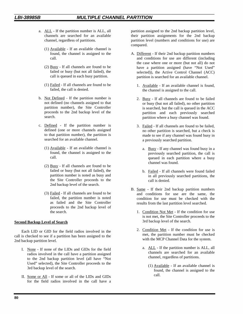
LBI-38985B MULTIPLE CHANNEL PARTITION
80
a. ALL - If the partition number is ALL, allchannels are searched for an availablechannel, regardless of partitions.
(1) Available - If an available channel isfound, the channel is assigned to thecall.
(2) Busy - If all channels are found to befailed or busy (but not all failed), thecall is queued in each busy partition.
(1) Failed - If all channels are found to befailed, the call is denied.
b. Not Defined - If the partition number isnot defined (no channels assigned to thatpartition number), the Site Controllerproceeds to the 2nd backup level of thesearch.
c. Defined - If the partition number isdefined (one or more channels assignedto that partition number), the partition issearched for an available channel.
(1) Available - If an available channel isfound, the channel is assigned to thecall.
(2) Busy - If all channels are found to befailed or busy (but not all failed), thepartition number is noted as busy andthe Site Controller proceeds to the2nd backup level of the search.
(3) Failed - If all channels are found to befailed, the partition number is notedas failed and the Site Controllerproceeds to the 2nd backup level ofthe search.
Second Backup Level of Search
Each LID or GID for the field radios involved in thecall is checked to see if a partition has been assigned to the2nd backup partition level.
I. None - If none of the LIDs and GIDs for the fieldradios involved in the call have a partition assignedto the 2nd backup partition level (all have “NotUsed” selected), the Site Controller proceeds to the3rd backup level of the search.
II. Some or All - If some or all of the LIDs and GIDsfor the field radios involved in the call have a
partition assigned to the 2nd backup partition level,their partition assignments for the 2nd backuppartition level (numbers and conditions for use) arecompared.
A. Different - If their 2nd backup partition numbersand conditions for use are different (includingthe case where one or more (but not all) do nothave a partition assigned (have “Not Used”selected)), the Active Control Channel (ACC)partition is searched for an available channel.
1. Available - If an available channel is found,the channel is assigned to the call.
2. Busy - If all channels are found to be failedor busy (but not all failed), no other partitionis searched, but the call is queued in the ACCpartition and each previously searchedpartition where a busy channel was found.
3. Failed - If all channels are found to be failed,no other partition is searched, but a check ismade to see if any channel was found busy ina previously searched partition.
a. Busy - If any channel was found busy in apreviously searched partition, the call isqueued in each partition where a busychannel was found.
b. Failed - If all channels were found failedin all previously searched partitions, thecall is denied.
B. Same - If their 2nd backup partition numbersand conditions for use are the same, thecondition for use must be checked with theresults from the last partition level searched.
1. Condition Not Met - If the condition for useis not met, the Site Controller proceeds to the3rd backup level of the search.
2. Condition Met - If the condition for use ismet, the partition number must be checkedwith the MCP Channel Data for the system.
a. ALL - If the partition number is ALL, allchannels are searched for an availablechannel, regardless of partitions.
(1) Available - If an available channel isfound, the channel is assigned to thecall.
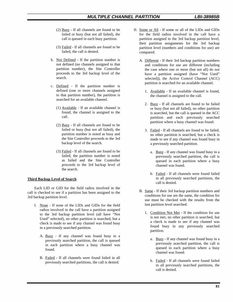
MULTIPLE CHANNEL PARTITION LBI-38985 B
81
(2) Busy - If all channels are found to befailed or busy (but not all failed), thecall is queued in each busy partition.
(3) Failed - If all channels are found to befailed, the call is denied.
b. Not Defined - If the partition number isnot defined (no channels assigned to thatpartition number), the Site Controllerproceeds to the 3rd backup level of thesearch.
c. Defined - If the partition number isdefined (one or more channels assignedto that partition number), the partition issearched for an available channel.
(1) Available - If an available channel isfound, the channel is assigned to thecall.
(2) Busy - If all channels are found to befailed or busy (but not all failed), thepartition number is noted as busy andthe Site Controller proceeds to the 3rdbackup level of the search.
(3) Failed - If all channels are found to befailed, the partition number is notedas failed and the Site Controllerproceeds to the 3rd backup level ofthe search.
Third Backup Level of Search
Each LID or GID for the field radios involved in thecall is checked to see if a partition has been assigned to the3rd backup partition level.
I. None - If none of the LIDs and GIDs for the fieldradios involved in the call have a partition assignedto the 3rd backup partition level (all have “NotUsed” selected), no other partition is searched, but acheck is made to see if any channel was found busyin a previously searched partition.
A. Busy - If any channel was found busy in apreviously searched partition, the call is queuedin each partition where a busy channel wasfound.
B. Failed - If all channels were found failed in allpreviously searched partitions, the call is denied.
II. Some or All - If some or all of the LIDs and GIDsfor the field radios involved in the call have apartition assigned to the 3rd backup partition level,their partition assignments for the 3rd backuppartition level (numbers and conditions for use) arecompared.
A. Different - If their 3rd backup partition numbersand conditions for use are different (includingthe case where one or more (but not all) do nothave a partition assigned (have “Not Used”selected)), the Active Control Channel (ACC)partition is searched for an available channel.
1. Available - If an available channel is found,the channel is assigned to the call.
2. Busy - If all channels are found to be failedor busy (but not all failed), no other partitionis searched, but the call is queued in the ACCpartition and each previously searchedpartition where a busy channel was found.
3. Failed - If all channels are found to be failed,no other partition is searched, but a check ismade to see if any channel was found busy ina previously searched partition.
a. Busy - If any channel was found busy in apreviously searched partition, the call isqueued in each partition where a busychannel was found.
b. Failed - If all channels were found failedin all previously searched partitions, thecall is denied.
B. Same - If their 3rd backup partition numbers andconditions for use are the same, the condition foruse must be checked with the results from thelast partition level searched.
1. Condition Not Met - If the condition for useis not met, no other partition is searched, buta check is made to see if any channel wasfound busy in any previously searchedpartition.
a. Busy - If any channel was found busy in apreviously searched partition, the call isqueued in each partition where a busychannel was found.
b. Failed - If all channels were found failedin all previously searched partitions, thecall is denied.

LBI-38985B MULTIPLE CHANNEL PARTITION
82
2. Condition Met - If the condition for use ismet, the partition number must be checkedwith the MCP Channel Data for the system.
a. ALL - If the partition number is ALL, allchannels are searched for an availablechannel, regardless of partitions.
(1) Available - If an available channel isfound, the channel is assigned to thecall.
(2) Busy - If all channels are found to befailed or busy (but not all failed), thecall is queued in each busy partition.
(3) Failed - If all channels are found to befailed, the call is denied.
b. Not Defined - If the partition number isnot defined (no channels assigned to thatpartition number), no other partition issearched, but a check is made to see ifany channel was found busy in anypreviously searched partition.
(1) Busy - If any channel was found busyin a previously searched partition, thecall is queued in each partition wherea busy channel was found.
(2) Failed - If all channels were foundfailed in all previously searchedpartitions, the call is denied.
c. Defined - If the partition number isdefined (one or more channels assignedto that partition number), the partition issearched for an available channel.
(1) Available - If an available channel isfound, the channel is assigned to thecall.
(2) Busy - If all channels are found to befailed or busy (but not all failed), noother partition is searched, but the callis queued in each partition where abusy channel was found.
(3) Failed - If all channels are found to befailed, no other partition is searched,but a check is made to see if anychannel was found busy in apreviously searched partition.
(a) Busy - If any channel was foundbusy in a previously searchedpartition, the call is queued ineach partition where a busychannel was found.
(b) Failed - If all channels were foundfailed in all previously searchedpartitions, the call is denied.
Call Queuing
A call is queued only after all channels that wereallowed to be searched were found to be failed or busy (butnot all failed). At that time the call is queued in eachsearched partition where one or more busy channels werefound. As soon as a channel becomes available in anypartition where the call was queued, the available channel isassigned to the call and the call is removed from the queuein all partitions where the call was queued.
Call Denial
A call is denied only after all channels that wereallowed to be searched were found to be either failed (nonebusy) or unable to support the call request (i.e., digital, data,wide area, etc.). This is assuming the IDs are valid and thattheir database partition assignments exist on the site(s).Also, if all assigned partitions for the IDs involved in thecall are not defined (do not exist) for the site and theconditions for using the ACC Partition are not met, the callwill be denied.
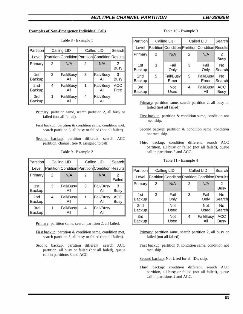
MULTIPLE CHANNEL PARTITION LBI-38985 B
83
Examples of Non-Emergency Individual Calls
Table 8 - Example 1
Partition Calling LID Called LID Search
Level Partition Condition Partition Condition Results
Primary 2 N/A 2 N/A 2Busy
1stBackup
3 Fail/BusyAll
3 Fail/BusyAll
3Busy
2ndBackup
4 Fail/BusyAll
1 Fail/BusyAll
ACCFree
3rdBackup
1 Fail/BusyAll
4 Fail/BusyAll
Primary: partition same, search partition 2, all busy orfailed (not all failed).
First backup: partition & condition same, condition met,search partition 3, all busy or failed (not all failed).
Second backup: partition different, search ACCpartition, channel free & assigned to call.
Table 9 - Example 2
Partition Calling LID Called LID Search
Level Partition Condition Partition Condition Results
Primary 2 N/A 2 N/A 2Failed
1stBackup
3 Fail/BusyAll
3 Fail/BusyAll
3Busy
2ndBackup
4 Fail/BusyAll
1 Fail/BusyAll
ACCBusy
3rdBackup
1 Fail/BusyAll
4 Fail/BusyAll
Primary: partition same, search partition 2, all failed.
First backup: partition & condition same, condition met,search partition 3, all busy or failed (not all failed).
Second backup: partition different, search ACCpartition, all busy or failed (not all failed), queuecall in partitions 3 and ACC.
Table 10 - Example 3
Partition Calling LID Called LID Search
Level Partition Condition Partition Condition Results
Primary 2 N/A 2 N/A 2Busy
1stBackup
3 FailOnly
3 FailOnly
NoSearch
2ndBackup
5 Fail/BusyEmer
5 Fail/BusyEmer
NoSearch
3rdBackup
NotUsed
4 Fail/BusyAll
ACCBusy
Primary: partition same, search partition 2, all busy orfailed (not all failed).
First backup: partition & condition same, condition notmet, skip.
Second backup: partition & condition same, conditionnot met, skip.
Third backup: condition different, search ACCpartition, all busy or failed (not all failed), queuecall in partitions 2 and ACC.
Table 11 - Example 4
Partition Calling LID Called LID Search
Level Partition Condition Partition Condition Results
Primary 2 N/A 2 N/A 2Busy
1stBackup
3 FailOnly
3 FailOnly
NoSearch
2ndBackup
NotUsed
NotUsed
NoSearch
3rdBackup
NotUsed
4 Fail/BusyAll
ACCBusy
Primary: partition same, search partition 2, all busy orfailed (not all failed).
First backup: partition & condition same, condition notmet, skip.
Second backup: Not Used for all IDs, skip.
Third backup: condition different, search ACCpartition, all busy or failed (not all failed), queuecall in partitions 2 and ACC.

LBI-38985B MULTIPLE CHANNEL PARTITION
84
Examples of Non-Emergency Group Calls
Table 12 - Example 5
Partition Called GID Search
Level Partition Condition Results
Primary 2 N/A 2Busy
1stBackup
3 FailOnly
NoSearch
2ndBackup
4 Fail/BusyEmer
NoSearch
3rdBackup
1 Fail/BusyAll
1Busy
Primary: partition same, search partition 2, all busy orfailed (not all failed).
First backup: partition & condition same, condition notmet, skip.
Second backup: partition & condition same, conditionnot met, skip.
Third backup: partition & condition same, conditionmet, search partition 1, all busy or failed (not allfailed), queue call in partitions 1 and 2.
Table 13 - Example 6
Partition Called GID Search
Level Partition Condition Results
Primary 2 N/A 2Busy
1stBackup
3 Fail/BusyEmer
NoSearch
2ndBackup
4 Fail/BusyAll
4Free
3rdBackup
1 Fail/BusyAll
Primary: one GID (group call), search partition 2, allbusy or failed (not all failed).
First backup: one GID (group call), condition not met,skip.
Second backup: one GID (group call), condition met,search partition 4, channel free & assigned to call.
Examples of Emergency Group Calls
Table 14 - Example 7
Partition Called GID Search
Level Partition Condition Results
Primary 2 N/A 2Busy
1stBackup
3 FailOnly
NoSearch
2ndBackup
4 Fail/BusyEmer
4Free
3rdBackup
1 Fail/BusyAll
Primary: one GID (group call), search partition 2, allbusy or failed (not all failed).
First backup: one GID (group call), condition not met,skip.
Second backup: one GID (group call), condition met,search partition 4, channel free & assigned to call.
Table 15 - Example 8
Partition Called GID Search
Level Partition Condition Results
Primary 2 N/A 2Busy
1stBackup
3 Fail/BusyAll
3Busy
2ndBackup
4 Fail/BusyEmer
4Busy
3rdBackup
1 FailOnly
NoSearch
Primary: one GID (group call), search partition 2, allbusy or failed (not all failed).
First backup: one GID (group call), condition met,search partition 3, all busy or failed (not all failed).
Second backup: one GID (group call), condition met,search partition 4, all busy or failed (not all failed).
Third backup: one GID (group call), condition not met,skip, queue call in partitions 2, 3, and 4.

MAINTENANCE LBI-38985 B
85
MAINTENANCE
SOFTWARE REPLACEMENT
This instruction applies only to a VAX model (ora PDP-11 model that has been upgraded to aVAX model) of Site Controller computer.
NOTE
The Site Controller contains Application Software (theoperational instructions) and a Personality (the operationalparameters for a specific system). If the customer has notspecified what parameters are needed for its system by thetime the EDACS Site Controller is assembled in the factory,a generic personality is installed. The values for some of theparameters in this generic personality are not the SiteController default values. The generic personality isdesigned to allow factory test and initial installation checkout. It is meant to be replaced with a customer-specificpersonality before the EDACS system is put in operation.
The Application Software is contained in a set of 14PROMs; the Personality in a set of 2 PROMs. Both PROMsets are mounted on the MRV11-D PROM Card. If theApplication Software or Personality ever needs to bereplaced, remove the PROM card, replace the applicable setof PROMs, and return the PROM card to the .
PROM Card Removal
The following three procedures correspond to the threedifferent package designs used for the various models of SiteController.
Back Entry with RJ11-Type Connectors
The latest VAX model is characterized by the modularRJ11-type connectors on its back panel. Access to thePROM card is through the back using the followingprocedure:
1. Turn off the Site Controller (switch is on the back).
2. Loosen the two fastener screws holding the backpanel to the chassis (see Figure 10).
2345678
15
28293031
1
0 SM
14 13 12 11 10 9
27 26 25 24
20212223
19 18 17 16
FastenerScrews
Figure 10 - Location of Fastener Screws
3. Rotate the back panel down and out of the way (becareful not to damage the ribbon cables).
PROM Card
Figure 11 - PROM Card Location In Later VAX
4. Remove the PROM Card (see Figure 11) by pullingon the two tabs fastened to the front edge of thecard. Once the card has disengaged the connector,use one hand to push up on the board above to helpprevent the PROM Card from dragging as it ispulled out. (Observe standard handling practicesfor static sensitive components.)
Back-Entry with DILOG or EMULEX Panels
The earlier VAX models and later PDP-11 models arecharacterized by the DILOG or EMULEX panels connectedto the by ribbon cables. Access to the PROM card is throughthe back using the following procedure:
1. Turn off the Site Controller (switch is on the back).
2. Loosen the two fastener screws holding the backpanel to the chassis (see Figure 12).
Fastener Screws
Figure 12 - Fastener Screw Location In Earlier VAX
3. Lift the back panel out of the way.
4. Remove the PROM Card (see Figure 13) by pullingon the two tabs fastened to the front edge of thecard. Once the card has disengaged the connector,

LBI-38985B MAINTENANCE
86
use one hand to push up on the board above to helpprevent the PROM Card from dragging as it ispulled out. (Be careful not to damage the ribboncables and observe standard handling practices forstatic sensitive components.)
PROM Card
Figure 13 - PROM Card Location In Earlier VAX
Top-Entry with DILOG or EMULEX Panels
The earliest PDP-11 model is also characterized by theDILOG or EMULEX panels connected to the by ribboncables. However, access to the PROM card is through a lift-up door in the top using the following procedure:
1. Turn off the Site Controller (switch is on the back).
2. Pull the Site Controller chassis all the way forwardon its slide-out track.
3. Pull up the top cover with the attached card cage,and have someone other than you hold it up.
PROM Card
Figure 14 - PROM Card Location for Top Entry
4. Remove the PROM Card (see Figure 14) by pullingon the two tabs fastened to the front edge of thecard. Once the card has disengaged the connector,use one hand to push up on the board above to helpprevent the PROM Card from dragging as it ispulled out. (Observe standard handling practicesfor static sensitive components.)
PROM Replacement
The locations of the Personality and ApplicationSoftware PROMs on the MRV11-D PROM card is shown inFigure 15. Before replacing PROMs, review the followinglist of suggestions:
• Replace PROMs as a set only.
• Put each PROM in its correct location. Beespecially careful of location numbers 01 and 02since these numbers are used for both sets ofPROMs.
• Orient each PROM with the notched end as shown.
• Make sure no PROM leads get bent under thePROM during insertion into the socket.
• Observe standard handling practices for static-sensitive components.
03 040201
08070605
09 1011 12
13 1401 02
PersonalityPROMs01-02
SoftwareApplication
PROMs01-14
Figure 15 - Location of PROMs on PROM Card
Application Software PROMs
A typical Application Software PROM label is shown inFigure 16. All 14 PROMs in the set must be marked with thesame software revision number, and must be marked with adifferent PROM location number.

MAINTENANCE LBI-38985 B
87
Figure 16 - Application Software PROM Label
Personality PROMs
A typical Personality PROM label is shown in Figure17. Both PROMs in the set must be marked with the sameserial number, and must be marked with a different PROMlocation number.
Figure 17 - Personality PROM Label
CABINET VENTILATION
Clean the air filter in the cabinet door at regularintervals. Failure to do so may causeoverheating and failure of the equipment.
CAUTION
Periodically check the operation of the cabinet-top fanand clean the air filter in the cabinet door to preventoverheating and failure of the equipment.
POWER SENSOR CALIBRATION
If the system includes a Power Monitor Unit, theindividual transmitter and antenna power sensors should bere-calibrated every six months. Use the procedure describedin the maintenance manual for the Power Monitor Unit.
LBI-38985B TROUBLESHOOTING
88
TROUBLESHOOTING
GENERAL
The following three techniques are especially useful fortroubleshooting EDACS Site Controllers:
1. Comparison - Compare all of the readily measurableparameters of a suspect assembly with an identical,known-to-be-good assembly. If a significant differenceis found, then the problem may have been located.
2. Substitution - Exchange the suspect assembly with anidentical, known-to-be-good assembly. If the problemmoves, then the defective component must have movedalso.
3. Divide and Conquer - Divide the equipment in half andfind a symptom of the problem that appears in one halfonly. Then divide that half in half and repeat until youcome to a point where the problem exists on one side ofa replaceable component and not on the other.
RECOVERY FROM FAILSOFT
If the site switches from the Full-Featured Trunkingmode of operation to the Failsoft Trunking mode ofoperation, the following steps should be taken to return thesite to the Full-Featured Trunking mode of operation:
1. Momentarily press the S4 (RESET) button on the frontedge of the largest board in the Control Channel GETCshelf. This should return the site to the Full-FeaturedTrunking mode of operation within 1 or 2 seconds.
2. If step 1 fails, momentarily press the S4 button on allstation GETCs simultaneously (within a few seconds ofeach other - the last one must be started before the firstone completes its reset). An alternative method is toturn off all Station GETCs (turn off each repeater’s DCPower Supply) until all are off. Then power up onerepeater at a time. This should return the site to the Full-Featured Trunking mode of operation.
3. If steps 1 and 2 fail, press and hold down the S4 buttonon all Working Channel GETCs, then momentarilypress the S4 button on the Control Channel GETC.When the site returns to the Full-Featured Trunkingmode of operation, release the S4 button on eachWorking Channel GETC. The site should remain in theFull-Featured Trunking mode of operation.
4. If steps 1, 2, and 3 fail, reset the Site Controller (see theSite Controller Reset heading). Wait 1 1/2 minutes tomake sure that the Site Controller has finished its reset.Then return to step 1.
SITE CONTROLLER RESET
If the site will not come out of the Failsoft Trunkingmode of operation by resetting the GETCs, then the SiteController should be reset. To reset the Site Controller, pressthe “Restart/Run” button or, on some models, press the“Halt” and then the “Start” buttons.
TROUBLESHOOTING GUIDES
Troubleshooting guides may be found in the manualsfor the individual pieces of equipment used with the SiteController. Table 16 consists of a troubleshooting guide forMCP-related problems. Find the applicable symptom. Thenlook at each possible cause. When the cause is found, youmay want to take the corrective action or leave as is.

TROUBLESHOOTING LBI-38985 B
89
Table 16 - Multiple Channel Partition (MCP) Troubleshooting Guide
SYMPTOM POSSIBLE CAUSE(S) CORRECTIVE ACTION
Group voice or data call isdenied.
Partition not defined at site. Use different group or definepartition for that site.
No digital channels in partition. Assign digital channel to partition.
No data channels in partition. Assign data channel to partition.
ACC partition moved to called group’spartition and it only has one channeldefined, which is now the ControlChannel, so there are no workingchannels in the partition.
From the reconfiguration screen ofthe System Manager, only allow theControl Channel on channels inpartitions with at least two channelsassigned to them.
Individual voice call is denied. If both radios are in same partition thepartition may not be defined at site.
In the site database maintenancescreen, define partition for that site.Also, from the site reconfigurationscreen, send the new channel MCPdata.
No digital channels in partition. Assign digital channel to partition.
If both radios in same partition and ACCmoved to that partition or radios indifferent partitions, the ACC partition maybe located in partition with only onechannel, which is now the ControlChannel, so there are no WorkingChannels in that partition.
From the reconfiguration screen ofthe System Manager, only allow theControl Channel on channels inpartitions with at least two channelsassigned to them.
Individual data call is denied. Data radio’s partition may not be definedat site.
In the site database maintenancescreen, define partition for that site.Also, from the site reconfigurationscreen, send the new channel MCPdata.
No data channels in partition. Assign data channel to partition.
ACC partition moved to data radio’spartition and it only has one channeldefined, which is now the ControlChannel, so there are no WorkingChannels in the partition.
From the reconfiguration screen ofthe System Manager, only allow theControl Channel on channels inpartitions with at least two channelsassigned to them.
Dynamic Regroup call isdenied.
ACC partition moved to partition that onlyhas one channel defined, which is nowthe Control Channel, so there are noWorking Channels in the partition.
From the reconfiguration screen ofthe System Manager, only allow theControl Channel on channels inpartitions with at least two channelsassigned to them.
System All-Call is denied. ACC partition may have moved to apartition that only has one channeldefined, which is now the ControlChannel, so there are no WorkingChannels in the partition.
From the reconfiguration screen ofthe System Manager, only allow theControl Channel on channels inpartitions with at least two channelsassigned to them.
(Continued)

LBI-38985B TROUBLESHOOTING
90
Table 16 - Multiple Channel Partition (MCP) Troubleshooting Guide (Continued)
SYMPTOM POSSIBLE CAUSE(S) CORRECTIVE ACTION
Patch activation is denied. If all GIDs are in the same partition,partition may not be defined at one ofmore of the sites.
In the site database maintenancescreen, ensure that partitions aredefined for all of the sites. Also,from the site reconfiguration screen,send the new channel MCP data.
If GIDs are in different partitions at one ormore of the sites, the ACC partition mayhave moved to a partition that only hasone channel defined, which is now theControl Channel, so there are noWorking Channels in the partition.
From the reconfiguration screen ofthe System Manager, only allow theControl Channel on channels inpartitions with at least two channelsassigned to them, for all sites.
Group Simulselect activation isdenied.
If all GIDs are in the same partition,partition may not be defined at one ofmore of the sites.
In the site database maintenancescreen, ensure that partitions aredefined for all of the sites. Also,from the site reconfiguration screen,send the new channel MCP data.
If GIDs are indifferent partitions, at one ormore of the sites, the ACC partition mayhave moved to a partition that only hasone channel defined, which is now theControl Channel, so there are noWorking Channels in the partition.
From the reconfiguration screen ofthe System Manager, only allow theControl Channel on channels inpartitions with at least two channelsassigned to them, for all sites.
Individual Simulselectactivation is denied.
If all LIDs are in the same partition,partition may not be defined at one ofmore of the sites.
In the site database maintenancescreen, ensure that partitions aredefined for all of the sites. Also,from the site reconfiguration screen,send the new channel MCP data.
If LIDs are in different partitions, at oneor more of the sites, the ACC partitionmay have moved to a partition that onlyhas one channel defined, which is nowthe Control Channel, so there are noWorking Channels in the partition.
From the reconfiguration screen ofthe System Manager, only allow theControl Channel on channels inpartitions with at least two channelsassigned to them, for all sites.
LID & GID Simulselectactivation is denied.
If all LIDs & GIDs are in the samepartition, partition may not be defined atone of more of the sites.
In the site database maintenancescreen, ensure that partitions aredefined for all of the sites. Also,from the site reconfiguration screen,send the new channel MCP data.
If LIDs & GIDs are in different partitions,at one or more of the sites, the ACCpartition may have moved to a partitionthat only has one channel defined, whichis now the Control Channel, so there areno Working Channels in the partition.
From the reconfiguration screen ofthe System Manager, only allow theControl Channel on channels inpartitions with at least two channelsassigned to them, for all sites.
(Continued)

TROUBLESHOOTING LBI-38985 B
91
Table 16 - Multiple Channel Partition (MCP) Troubleshooting Guide (Continued)
SYMPTOM POSSIBLE CAUSE(S) CORRECTIVE ACTION
Radio-originated Local orCentral Interconnect call isdenied.
Calling radio’s partition may not bedefined at site.
In the site database maintenancescreen, define partition for that site.Also, from the site reconfigurationscreen, send the new channel MCPdata.
If this is a Local Interconnect call, thenumber called may be toll call restricted.
Change toll call restrictions for thecalling LID to allow called number.
If this is a Local Interconnect call, theremay not be any channels withinterconnect equipment in partition.
Assign interconnect channel topartition.
ACC partition moved to calling radio’spartition and it only has one channeldefined, which is now the ControlChannel, so there are no WorkingChannels in the partition.
From the reconfiguration screen ofthe System Manager, only allow theControl Channel on channels inpartitions with at least two channelsassigned to them.
Telephone-originated Local orCentral Interconnect call isdenied.
Called radio’s partition may not bedefined at site.
In the site database maintenancescreen, define partition for that site.Also, from the site reconfigurationscreen, send the new channel MCPdata.
If this is a Local Interconnect call, thecalled LID or GID may not be allowed toreceive Local Interconnect calls.
Enable LID or GID to receive LocalInterconnect calls.
If this is a Local Interconnect call, theremay not be any channels withinterconnect equipment in partition.
Assign interconnect channel topartition.
ACC partition moved to calling radio’spartition and it only has one channeldefined, which is now the ControlChannel, so there are no WorkingChannels in the partition.
From the reconfiguration screen ofthe System Manager, only allow theControl Channel on channels inpartitions with at least two channelsassigned to them.
Multisite call is not assigned tosome sites.
Call’s partition may not be defined at allsites.
In the site database maintenancescreen, ensure that partitions aredefined for all of the sites. Also,from the site reconfiguration screen,send the new channel MCP data.
ACC partition may have moved to apartition that only has one channeldefined, which is now the ControlChannel, so there are no WorkingChannels in the partition.
From the reconfiguration screen ofthe System Manager, only allow theControl Channel on channels inpartitions with at least two channelsassigned to them.
(Continued)
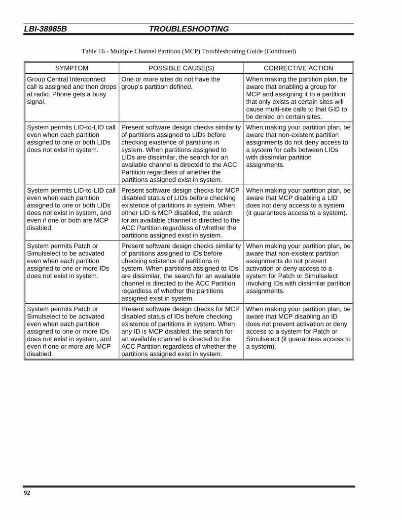
LBI-38985B TROUBLESHOOTING
92
Table 16 - Multiple Channel Partition (MCP) Troubleshooting Guide (Continued)
SYMPTOM POSSIBLE CAUSE(S) CORRECTIVE ACTION
Group Central Interconnectcall is assigned and then dropsat radio. Phone gets a busysignal.
One or more sites do not have thegroup’s partition defined.
When making the partition plan, beaware that enabling a group forMCP and assigning it to a partitionthat only exists at certain sites willcause multi-site calls to that GID tobe denied on certain sites.
System permits LID-to-LID calleven when each partitionassigned to one or both LIDsdoes not exist in system.
Present software design checks similarityof partitions assigned to LIDs beforechecking existence of partitions insystem. When partitions assigned toLIDs are dissimilar, the search for anavailable channel is directed to the ACCPartition regardless of whether thepartitions assigned exist in system.
When making your partition plan, beaware that non-existent partitionassignments do not deny access toa system for calls between LIDswith dissimilar partitionassignments.
System permits LID-to-LID calleven when each partitionassigned to one or both LIDsdoes not exist in system, andeven if one or both are MCPdisabled.
Present software design checks for MCPdisabled status of LIDs before checkingexistence of partitions in system. Wheneither LID is MCP disabled, the searchfor an available channel is directed to theACC Partition regardless of whether thepartitions assigned exist in system.
When making your partition plan, beaware that MCP disabling a LIDdoes not deny access to a system(it guarantees access to a system).
System permits Patch orSimulselect to be activatedeven when each partitionassigned to one or more IDsdoes not exist in system.
Present software design checks similarityof partitions assigned to IDs beforechecking existence of partitions insystem. When partitions assigned to IDsare dissimilar, the search for an availablechannel is directed to the ACC Partitionregardless of whether the partitionsassigned exist in system.
When making your partition plan, beaware that non-existent partitionassignments do not preventactivation or deny access to asystem for Patch or Simulselectinvolving IDs with dissimilar partitionassignments.
System permits Patch orSimulselect to be activatedeven when each partitionassigned to one or more IDsdoes not exist in system, andeven if one or more are MCPdisabled.
Present software design checks for MCPdisabled status of IDs before checkingexistence of partitions in system. Whenany ID is MCP disabled, the search foran available channel is directed to theACC Partition regardless of whether thepartitions assigned exist in system.
When making your partition plan, beaware that MCP disabling an IDdoes not prevent activation or denyaccess to a system for Patch orSimulselect (it guarantees access toa system).

PARTS LIST LBI-38985 B
93
PARTS LIST
Most parts are listed in the specific manual for theequipment of which they are part, or with which they areassociated (see the listing of manuals in the Introduction ofthis manual). The parts used in the EDACS Site Controllerthat are not included in one of these manuals are listed here.
PART NO. DESCRIPTION- - - - SITE CONTROLLER (COMPUTER) - - - -
19A149302P9 Site Controller (Computer)
344A3265G6 Application Software PROM Set
Special Order Personality Software PROM Set
19D903880P61 Cable, Site Controller to GETC DATA Modules
19D903880P905 Cable, Site Controller (SM Port) to Modem
- - - - STATION POWER SUPPLY - - - -
19A149326G8 Hardware Kit for Station Power Supply Mounting
344A4119G1 Connector Kit for High Current Connection
19A149357G2 Cable, DC Power
- - - - UPS - - - -
349A9866P1 UPS, 120 VAC
188D5464P1 UPS Shelf, 120 VAC
349A9937G1 Hardware Kit for UPS Shelf
349A9866P2 UPS, 230 VAC
188D5465P1 UPS Shelf, 230 VAC
LTN3152/3 AC Outlet Strip, 230 VAC, 2 Outlets
349A9937G1 Hardware Kit for UPS Shelf
PART NO. DESCRIPTION- - - - CABINET - - - -
19D417358G3 69” Enclosed Cabinet with Front and Back Doors
19B801476P1 Bottom Cover for Cabinet
19B801476P2 Top Cover for Cabinet
19D417623G2 Grill Assembly (above front door)
19B226318P2 Sealing Plate for Grill Assembly (above front door)
19B226371G2 Sealing Plate Assembly for Top Vent in Back Door
19B200425P2 Air Filter for Bottom Vent in Back Door
19B209539P1 Front Door Handle and Lock Assembly
19B209539P2 Back Door Lock Assembly
19B209539P3 Key for Front and Back Door Locks
19A130031G12 Cabinet Hardware Kit
- - - - FAN - - - -
19C320895G12 Cabinet Fan Assembly, 120 VAC, 2-Speed
19C320895G15 Cabinet Fan Assembly, 230 VAC, 2-Speed
19A130166G2 Hardware Kit for Cabinet Fan Mounting
- - - - AC OUTLETS - - - -
19B226209G1 AC Outlet Strip, 120 VAC, 6 Outlets
19B226350G2 AC Outlet Strip, 120 VAC, 2 Outlets
- - - - BLANK PANELS - - - -
19C336871P1 Blank Panel - 1 Rack Unit
19C336871P2 Blank Panel - 2 Rack Units
19C336871P3 Blank Panel - 3 Rack Units
- - - - GROUND BUS - - - -
344A4730G1 Cabinet Ground Bus Kit

LBI-38985B GLOSSARY
94
GLOSSARY
ACC Partition................................................ See Active Control Channel Partition.
Active Control Channel Partition.................. The Active Control Channel (ACC) partition is the partition presently containingthe Control Channel, in a system using the Multiple Channel Partition (MCP)option.
Active Configuration..................................... The Active Configuration is the complete set of presently active (currently beingused) values for the configurable parameters for a specific piece of equipment.The active configuration may consist entirely of the default values set duringpower-up or reset, or may have some or all values subsequently reconfigured.
Allowed CC .................................................. The Allowed CC (Control Channel) parameter defines (for a system’s set ofchannels) which channels may be used as Control Channels.
Application Software .................................... The Application Software is the software that runs a device (an executableprogram). Several versions of Application Software may be written for a singledevice; one for each of several applications.
Backup Serial Line........................................ The Backup Serial Line is a data bus used for communications between GETCsduring Failsoft Trunking. It is connected to each Station, Downlink, and UplinkGETC in an EDACS system.
Basic EDACS System................................... A Basic EDACS System uses Failsoft Repeaters, operating in the TrunkedFailsoft mode, to provide voice and data trunked radio communications for anEDACS site.
BSL............................................................... See Backup Serial Line.
Control Channel ............................................ A Control Channel is any allowed radio channel (only one at a time) at anEDACS Trunked Site that is used for call requests and Working Channelassignments for trunked calls.
Control Channel GETC................................. The Control Channel GETC is the specific Station GETC that is connected to theEDACS repeater currently assigned as the Control Channel.
Controller ...................................................... See Site Controller Computer.
Downlink GETC ........................................... The Downlink GETC is the communications interface between an EDACSRepeater site and the Downlink to the IMC.
EDACS ......................................................... EDACS, short for Enhanced Digital Access Communications System, is aregistered trademark of Ericsson Inc. It is used by Ericsson to describe specificcommunications systems and their specific equipment which meet or exceed theneeds of the Public Service, Industrial, Commercial, and Utility markets world-wide.
EDACS Site Controller ................................. The EDACS Site Controller is made up of the Site Controller cabinet, the SiteController computer, and any supporting equipment that is mounted in the SiteController cabinet.
Failsoft Trunking........................................... Failsoft Trunking refers to basic EDACS trunking under the direction of theControl Channel GETC. This is the normal mode of trunking for a BasicEDACS repeater site having no EDACS Site Controller, or the backup mode oftrunking for an EDACS repeater site having an EDACS Site Controller.
Full-Featured Trunking ................................. Full-Featured Trunking refers to EDACS trunking under the direction of theEDACS Site Controller. It provides additional features beyond the basic featuresprovided by Failsoft Trunking.
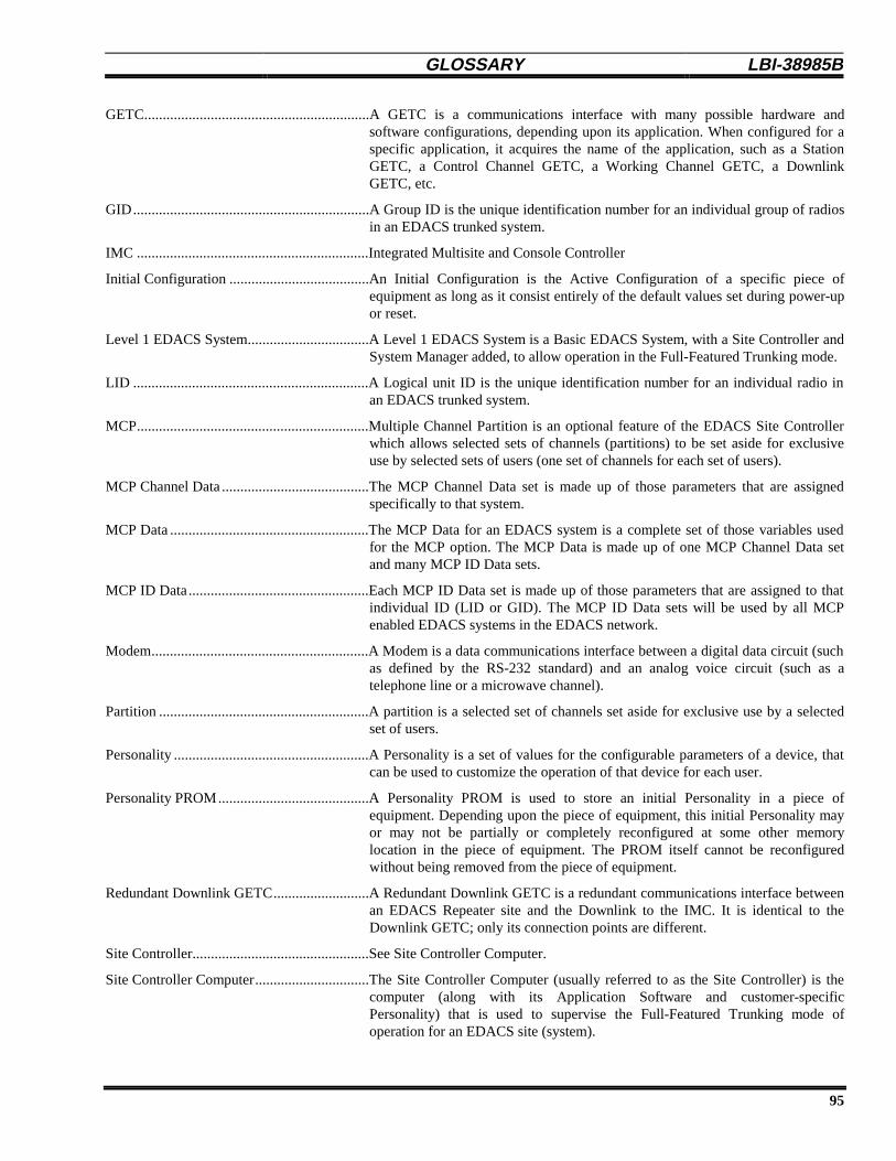
GLOSSARY LBI-38985 B
95
GETC.............................................................A GETC is a communications interface with many possible hardware andsoftware configurations, depending upon its application. When configured for aspecific application, it acquires the name of the application, such as a StationGETC, a Control Channel GETC, a Working Channel GETC, a DownlinkGETC, etc.
GID................................................................A Group ID is the unique identification number for an individual group of radiosin an EDACS trunked system.
IMC ...............................................................Integrated Multisite and Console Controller
Initial Configuration ......................................An Initial Configuration is the Active Configuration of a specific piece ofequipment as long as it consist entirely of the default values set during power-upor reset.
Level 1 EDACS System.................................A Level 1 EDACS System is a Basic EDACS System, with a Site Controller andSystem Manager added, to allow operation in the Full-Featured Trunking mode.
LID ................................................................A Logical unit ID is the unique identification number for an individual radio inan EDACS trunked system.
MCP...............................................................Multiple Channel Partition is an optional feature of the EDACS Site Controllerwhich allows selected sets of channels (partitions) to be set aside for exclusiveuse by selected sets of users (one set of channels for each set of users).
MCP Channel Data ........................................The MCP Channel Data set is made up of those parameters that are assignedspecifically to that system.
MCP Data ......................................................The MCP Data for an EDACS system is a complete set of those variables usedfor the MCP option. The MCP Data is made up of one MCP Channel Data setand many MCP ID Data sets.
MCP ID Data.................................................Each MCP ID Data set is made up of those parameters that are assigned to thatindividual ID (LID or GID). The MCP ID Data sets will be used by all MCPenabled EDACS systems in the EDACS network.
Modem...........................................................A Modem is a data communications interface between a digital data circuit (suchas defined by the RS-232 standard) and an analog voice circuit (such as atelephone line or a microwave channel).
Partition .........................................................A partition is a selected set of channels set aside for exclusive use by a selectedset of users.
Personality .....................................................A Personality is a set of values for the configurable parameters of a device, thatcan be used to customize the operation of that device for each user.
Personality PROM.........................................A Personality PROM is used to store an initial Personality in a piece ofequipment. Depending upon the piece of equipment, this initial Personality mayor may not be partially or completely reconfigured at some other memorylocation in the piece of equipment. The PROM itself cannot be reconfiguredwithout being removed from the piece of equipment.
Redundant Downlink GETC..........................A Redundant Downlink GETC is a redundant communications interface betweenan EDACS Repeater site and the Downlink to the IMC. It is identical to theDownlink GETC; only its connection points are different.
Site Controller................................................See Site Controller Computer.
Site Controller Computer...............................The Site Controller Computer (usually referred to as the Site Controller) is thecomputer (along with its Application Software and customer-specificPersonality) that is used to supervise the Full-Featured Trunking mode ofoperation for an EDACS site (system).
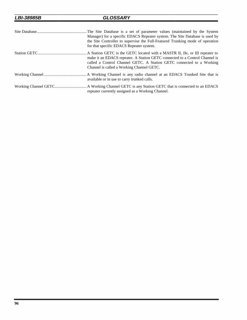
LBI-38985B GLOSSARY
96
Site Database................................................. The Site Database is a set of parameter values (maintained by the SystemManager) for a specific EDACS Repeater system. The Site Database is used bythe Site Controller to supervise the Full-Featured Trunking mode of operationfor that specific EDACS Repeater system.
Station GETC................................................ A Station GETC is the GETC located with a MASTR II, IIe, or III repeater tomake it an EDACS repeater. A Station GETC connected to a Control Channel iscalled a Control Channel GETC. A Station GETC connected to a WorkingChannel is called a Working Channel GETC.
Working Channel .......................................... A Working Channel is any radio channel at an EDACS Trunked Site that isavailable or in use to carry trunked calls.
Working Channel GETC............................... A Working Channel GETC is any Station GETC that is connected to an EDACSrepeater currently assigned as a Working Channel.

INTERCONNECTION DIAGRAMS LBI-38985 B
97
J1
J12
GETC DATA (Left)
J14
GETC DATA (Right)
J1
J8
J14
19D903880P61
19D903880P61Interconnect Cables (8 Each)
Interconnect Cables (12 Each)19C852313G1
19C852313G1
19C852447G1SERIAL MODULE
Interconnect Cable
Downlink GETC
J7 J100J102
TB10
J102J8 J100
Redundant Downlink GETC
TB10
Port 30 (RIC)
Port 26 (DL)
Port 25
19C852632G1POWER SENSOR
J3350A1380P1
Power Monitor Unit
188D6466P2
J4
J5
J6
Interconnect Cable (Chan 9-12)
Right VDT Interface Port 29 (PMU)
Port 2
Port 12
Port 14
Port 20
J1
J2
J9
Power Sensor Cables to
(Channels 1-12)
Xmtr Power Sensors(Channels 11-20)
Ant Power Sensors(Antennas 1-2)
(Channels 1-12)
Station GETCs J100(Channels 13-20)
Station GETCs J100
EDACS Interface Panel #119A149302P9
Site Controller Computer
J1
J2
and
19D903880P21
19D903880P21
Interconnect Cable
Interconnect Cable
19D903880P13
19D903880P13
Interconnect Cable
Interconnect Cable
Port 31 (LIC)
19D903880P91Interconnect Cable
19D903880P91Interconnect Cable
19D903880P101Interconnect Cable
EDACS Interface Panel #2
19C852204G1DWNLINK DATA
J1
J2
J14Downlink(s) toCEC / IMC
19B804709P1Interconnect Cable
J119D903880P101
Interconnect CableTest and Alarm Unit
Port 28 (ACU)
Port 27 (TU)
Line Data Port 0 (SM)
ZyXEL Modem
19D903880P905Interconnect Cable
Data Link toSystem Manager
J2
J2
Port 13
Port 1
19D904009G12
19D904009G13
EDACS Site Controller
Connection for
Connection for
Connection(s) for
Connection for
Connection for
Connection for
Connection for
Connection forData Links to
Data Links to
Xmtr Power Sensors
Power Sensor Cables to
Power Sensor Cables to
Station GETCs J102
Station GETCs J4
BSL / FSL to
J3 J4
Modem Shelf
J6 19B803256P1Interconnect Cable
(All Functions onBoth Connectors)
Reset / Status Lines to
AC Relay Panel19A149978P1 or P2
188D5366P1 (Earlier)
19A149786P3
J3
19B803826P1
19B803826P2Interconnect Cable
Connection for
Connection for
Data Link to
Data Link to
Master GTI Unit J4
Master GTI Unit J5
(RANGR or MDX Radio)
Connection forCable to
Test Unit Antenna
Connection forControl Cable to
Customer Equipment
J4
J5
J3
(C1-C8)
Connection forAlarm Cable to
Customer Equipment
Connection forAlarm Cable to
Customer Equipment
(A1-A16)
(A17-A32)
J5J8
Port #1
Port #2
Port #3
Port #4
Port #5
Port #7
J7
J8
188D6466P2Interconnect Cable (Chan 1-4)
188D6466P2Interconnect Cable (Chan 5-8)
188D6466P2Interconnect Cable (Chan 13-16)
188D6466P2Interconnect Cable (Chan 17-20)
188D6466P1Interconnect Cable (Ant 1-2)
188D6531P1 (Latest)
(Guardog)
Reset Unit
J8J6
(Guardog)
DB8860-Based
Orion TU Shelf
Interconnection Diagram 1 Latest Overall Configuration (3 or 4 Repeaters / Cabinet)
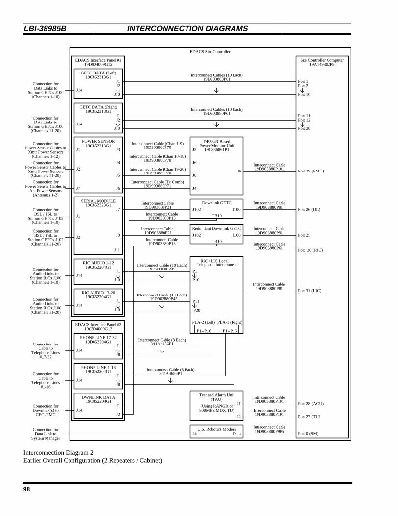
LBI-38985B INTERCONNECTION DIAGRAMS
98
J1
J10
GETC DATA (Left)
J14
GETC DATA (Right)
J1
J10J14
19D903880P61
19D903880P61Interconnect Cables (10 Each)
Interconnect Cables (10 Each)19C852313G1
19C852313G1
19C852323G1SERIAL MODULE
J11 19D903880P61Interconnect Cable
Downlink GETC
J7 J100J102
TB10
J102J8 J100
Redundant Downlink GETC
TB10
Port 30 (RIC)
Port 26 (DL)
Port 25
19C852213G1POWER SENSOR
J3 19C336861P1Power Monitor Unit19D903880P70
J4
J5
J6
19D903880P70
19D903880P70
Interconnect Cable (Chan 10-18)
Interconnect Cable (Chan 19-20)
Interconnect Cable (Chan 1-9)
Interconnect Cable (Tx Comb)19D903880P71
J5
J6
J8
J4
J9 Port 29 (PMU)
Port 2
Port 10
Port 12
Port 20
J1
J2
J7
Xmtr Power Sensors(Channels 1-12)
Xmtr Power Sensors(Channels 11-20)
Ant Power Sensors(Antennas 1-2)
(Channels 1-10)
Station GETCs J100(Channels 11-20)
Station GETCs J100
EDACS Interface Panel #119A149302P9
Site Controller Computer
J1
J2
(Channels 1-10)
(Channels 11-20)
19C852204G1RIC AUDIO 1-12 Telephone Interconnect
19D903880P21
19D903880P21
Interconnect Cable
Interconnect Cable
19D903880P13
19D903880P13
Interconnect Cable
Interconnect Cable
P1
P10
J1
J10
J1
J10
P11
P20
19C852204G1RIC AUDIO 13-20
19D903880P45
19D903880P45
Interconnect Cable (10 Each)
Interconnect Cable (10 Each)
Station RICs J100(Channels 1-10)
Station RICs J100(Channels 11-20)
19D852204G1PHONE LINE 17-32
J1
J8Telephone Lines#17-32
19C852204G1PHONE LINE 1-16
J1
J8Telephone Lines#1-16
19D903880P81Interconnect Cable
P1--P16 P1--P16
PLA-1 (Right)PLA-2 (Left)
Port 31 (LIC)
19D903880P91Interconnect Cable
19D903880P91Interconnect Cable
19D903880P101Interconnect Cable
EDACS Interface Panel #2
19C852204G1DWNLINK DATA
J1
J2J14Downlink(s) to
CEC / IMC
344A4656P1Interconnect Cable (8 Each)
344A4656P1Interconnect Cable (8 Each)
J2 19D903880P101Interconnect Cable
J1 19D903880P101Interconnect Cable(TAU)
Test and Alarm Unit
Port 28 (ACU)
Port 27 (TU)
Line Data Port 0 (SM)U.S. Robotics Modem 19D903880P905
Interconnect Cable
Data Link toSystem Manager
J2
J2
Port 11
Port 1
J14
J14
19D904009G12
19C904009G13
J14
J14
EDACS Site Controller
Connection for
Connection for
Connection for
Connection for
Connection for
Connection for
Connection for
Connection for
Connection for
Connection for
Connection for
Connection for
Connection for
RIC / LIC Local
Data Links to
Data Links to
Power Sensor Cables to
Power Sensor Cables to
Power Sensor Cables to
BSL / FSL toStation GETCs J102
Station GETCs J102BSL / FSL to
Audio Links to
Audio Links to
Cable to
Cable to
DB8843-Based
(Using RANGR or900MHz MDX TU)
Interconnection Diagram 2Earlier Overall Configuration (2 Repeaters / Cabinet)

INTERCONNECTION DIAGRAMS LBI-38985 B
99
J1
J12
GETC DATA (Left)
J14
GETC DATA (Right)
J1
J8J14
19D903880P61
19D903880P61Interconnect Cables (8 Each)
Interconnect Cables (12 Each)19C852313G1
19C852313G1
19C852323G1SERIAL MODULE
J11 19D903880P61Interconnect Cable
Downlink GETC
J7 J100J102
TB10
J102J8 J100
Redundant Downlink GETC
TB10
Port 30 (RIC)
Port 26 (DL)
Port 25
19C852213G1POWER SENSOR
J3 19C336861P1Power Monitor Unit19D903880P70
J4
J5
J6
19D903880P70
19D903880P70
Interconnect Cable (Chan 10-18)
Interconnect Cable (Chan 19-20)
Interconnect Cable (Chan 1-9)
Interconnect Cable (Tx Comb)19D903880P71
J5
J6
J8
J4
J9 Port 29 (PMU)
Port 2
Port 12
Port 14
Port 20
J1
J2
J7
Power Sensor Cables to
(Channels 1-12)
Xmtr Power Sensors(Channels 11-20)
Ant Power Sensors(Antennas 1-2)
(Channels 1-12)
Station GETCs J100(Channels 13-20)
Station GETCs J100
EDACS Interface Panel #119A149302P9
Site Controller Computer
J1
J2
(Channels 1-12)
(Channels 13-20)
19C852204G1RIC AUDIO 1-12 Telephone Interconnect
19D903880P21
19D903880P21
Interconnect Cable
Interconnect Cable
19D903880P13
19D903880P13
Interconnect Cable
Interconnect Cable
P1
P12
J1
J12
J1
J8
P13
P20
19C852204G1RIC AUDIO 13-20
19D903880P45
19D903880P45
Interconnect Cable (12 Each)
Interconnect Cable (8 Each)
RICs J100(Channels 1-12)
(Channels 13-20)
19C852204G1PHONE LINE 17-32
J1
J8Telephone Lines#17-32
19C852204G1PHONE LINE 1-16
J1
J8Telephone Lines#1-16
19D903880P81Interconnect Cable
P1--P16 P1--P16
PLA-1 (Right)PLA-2 (Left)
Port 31 (LIC)
19D903880P91Interconnect Cable
19D903880P91Interconnect Cable
19D903880P101Interconnect Cable
EDACS Interface Panel #2
19C852204G1DWNLINK DATA
J1
J2J14Downlink(s) to
CEC / IMC
344A4656P1Interconnect Cable (8 Each)
344A4656P1Interconnect Cable (8 Each)
J2 19D903880P101Interconnect Cable
J1 19D903880P101Interconnect Cable(TAU)
Test and Alarm Unit
Port 28 (ACU)
Port 27 (TU)
Line Data Port 0 (SM)U.S. Robotics Modem 19D903880P905
Interconnect Cable
Data Link toSystem Manager
J2
J2
Port 13
Port 1
J14
J14
19D904009G12
19D904009G13
J14
J14
EDACS Site Controller
Connection for
Connection for
Connection for
Connection for
Connection for
Connection for
Connection for
Connection for
Connection for
Connection for
Connection for
Connection for
Connection for
RIC / LIC Local
Data Links to
Data Links to
Xmtr Power Sensors
Power Sensor Cables to
Power Sensor Cables to
Station GETCs J102
Station GETCs J102BSL / FSL to
BSL / FSL to
RICs J100Audio Links to
Audio Links to
Cable to
Cable to
DB8843-Based
(Using RANGR or900MHz MDX TU)
Interconnection Diagram 3 Earlier Overall Configuration (3 Repeaters / Cabinet)

LBI-38985B INTERCONNECTION DIAGRAMS
100
Modem19A149786P2
Site Controller Computer19A149302P9
123
456
7820
22
SHIELDTX DATARX DATA
RTSCTSDSR
SIGNAL GNDDCDDTR
RING INDICATOR
PORT 0 (SM)
Cable19D903880P905
Chassis GroundTransmitted Data
Received Data
Request to SendClear to Send
Data Set Ready
Signal GroundCarrier Detect
Data Terminal Ready
Ring Indicate
EDACS Site Controller
DATADB-25 (F)
Right-handDB-25 (M)Modular 6 (M) Modular 6 (F)
1234
123
456
7820
22
DB-25 (F) DB-25 (M)P1 P2
Connection forData Link to
System Manager
Modem Shelf19D901989G2
56
Interconnection Diagram 4Latest System Manager Data Link (with ZyXEL Modem)
Modem19A149786P2
Site Controller Computer19A149302P9
123
456
7820
22
SHIELDTX DATARX DATA
RTSCTSDSR
SIGNAL GNDDCDDTR
RING INDICATOR
PORT 0 (SM)
Cable19D903880P905
Chassis GroundTransmitted Data
Received Data
Request to SendClear to Send
Data Set Ready
Signal GroundCarrier Detect
Data Terminal Ready
Ring Indicate
EDACS Site Controller
DATADB-25 (F)
Right-handDB-25 (M)Modular 6 (M) Modular 6 (F)
1234
123
456
7820
22
DB-25 (F) DB-25 (M)P1 P2
Telephone Line orEquivalent Circuit to
System Manager
J6 (Left-hand)Modular 6 (M) Modular 6 (F)
1234
Cable19B803262P1
Modem / Reset Unit Chassis188D5366P1
56
56
Interconnection Diagram 5Earlier System Manager Data Link (with U.S. Robotics Modem)

INTERCONNECTION DIAGRAMS LBI-38985 B
101
Cable19D903880P61
GETC DATA (Left)
EDACS Interface Panel #1
19C852313G1
Site Controller Computer19A149302P919D904009G12
Chan #1
J125-Pr Telco (F)J14
1272
327
Modular 8 (M)Modular 8 (F)
327
Modular 8 (M) Modular 8 (F)Port 1
25-Pr Telco (M)P1 P2
26RxTxGnd
Cable19D903880P61
J2
3294
327
Modular 8 (M)Modular 8 (F)
327
Modular 8 (M) Modular 8 (F)Port 2P1 P2
28RxTxGnd
Cable19D903880P61
J12
234924
327
Modular 8 (M)Modular 8 (F)
327
Modular 8 (M) Modular 8 (F)Port 12P1 P2
48RxTxGnd
Chan #2
Chan #12
GETC DATA (Right)19C852313G1
25-Pr Telco (F)J14
25-Pr Telco (M)
Cable19D903880P61
J1
1272
327
Modular 8 (M)Modular 8 (F)
327
Modular 8 (M) Modular 8 (F)Port 13P1 P2
26RxTxGnd
Chan #13
Cable19D903880P61
J2
3294
327
Modular 8 (M)Modular 8 (F)
327
Modular 8 (M) Modular 8 (F)Port 14P1 P2
28RxTxGnd
Chan #14
Cable19D903880P61
J8
154116
327
Modular 8 (M)Modular 8 (F)
327
Modular 8 (M) Modular 8 (F)Port 20P1 P2
40RxTxGnd
Chan #20
(Channels 1-12)
Station GETCs J100(Channels 13-20)
Station GETCs J100
Connection for
Connection forData Links to
Data Links to
Interconnection Diagram 6 Latest Station GETC Data Links (3 or 4 Repeaters / Cabinet)

LBI-38985B INTERCONNECTION DIAGRAMS
102
Cable19D903880P61
GETC DATA (Left)
EDACS Interface Panel #1
19C852313G1
Site Controller Computer19A149302P919D904009G12
Chan #1
J125-Pr Telco (F)J14
1272
327
Modular 8 (M)Modular 8 (F)
327
Modular 8 (M) Modular 8 (F)Port 1
25-Pr Telco (M)P1 P2
26RxTxGnd
Cable19D903880P61
J2
3294
327
Modular 8 (M)Modular 8 (F)
327
Modular 8 (M) Modular 8 (F)Port 2P1 P2
28RxTxGnd
Cable19D903880P61
J10
194520
327
Modular 8 (M)Modular 8 (F)
327
Modular 8 (M) Modular 8 (F)Port 10P1 P2
44RxTxGnd
Chan #2
Chan #10
GETC DATA (Right)19C852313G1
25-Pr Telco (F)J14
25-Pr Telco (M)
Cable19D903880P61
J1
1272
327
Modular 8 (M)Modular 8 (F)
327
Modular 8 (M) Modular 8 (F)Port 11P1 P2
26RxTxGnd
Chan #11
Cable19D903880P61
J2
3294
327
Modular 8 (M)Modular 8 (F)
327
Modular 8 (M) Modular 8 (F)Port 12P1 P2
28RxTxGnd
Chan #12
Cable19D903880P61
J10
194520
327
Modular 8 (M)Modular 8 (F)
327
Modular 8 (M) Modular 8 (F)Port 20P1 P2
44RxTxGnd
Chan #20
(Channels 1-10)
Station GETCs J100(Channels 11-20)
Station GETCs J100
Connection for
Connection forData Links to
Data Links to
Interconnection Diagram 7Earlier Station GETC Data Links (2 Repeaters / Cabinet)

INTERCONNECTION DIAGRAMS LBI-38985 B
103
Site Controller Computer
J100DB-9
19D903880P21
SERIAL MODULE
EDACS Interface Panel #1
TB10
Tx +Tx -Rx -Rx +
RxTxGNDGND
19D903880P91
19A149302P9
19D903880P13
19D904009G12
Downlink GETC Shelf
19C852447G1
J8DB-15J1
J102DB-9
6-Pin Modular
Cable
BSL (Failsoft)
GND
TxRx
8-Pin ModularPort #26 (DL)
Cable
3271
321
19D903880P91Cable
J7DB-15J2
6-Pin Modular
19C852204G1DWNLINK DATA
EDACS Interface Panel #219D904009G13
2435
TB10
Tx +Tx -Rx -Rx +
J1425-Pr Telco
126
227
J16-Pin Modular
J16-Pin Modular
328
429
9101112
2345 Cable
2345
9101112
J100DB-9
Redundant
321
J102DB-9
2435
RxTxGNDGND
8-Pin ModularPort #25
3271
Spade Lug
Spade Lug #6 Screw
#6 Screw
19D903880P21Cable
19D903880P13Cable
321
FSL (Sync)GND
GND
TxRx
321
BSL (Failsoft)FSL (Sync)GND
Main
Downlink GETC Shelf
J101DB-9
RxTxGNDGND
GND
TxRx
8-Pin ModularPort #25
3271
321
19D903880P91Cable
Site Controller Computer
19D903880P91
19A149302P9
Cable
J101DB-9
RxTxGNDGND
8-Pin ModularPort #26 (DL)
3271
GND
TxRx
321
Backup
Main
Main Downlinkto CEC / IMC
Connection for
Connection for
Station GETCsBSL / FSL to
Redundant Downlink to CEC / IMC
Connection for
Connection for
Station GETCsBSL / FSL to
12910
12910
(J102)
(J102)
Interconnection Diagram 8 Downlink GETCs

LBI-38985B INTERCONNECTION DIAGRAMS
104
Cable344A4656P1
PHONE LINE 1-16
EDACS Interface Panel #1
19C852204G1
RIC / LICLocal Telephone Interconnect19D904009G12
J125-Pr Telco (F)J14
1272
23
4
Modular 6 (M)Modular 6 (F)
3
Modular 6 (M) Modular 6 (F)J1
25-Pr Telco (M)P1 P2
26
34
Modular 6 (M) Modular 6 (F)J2P2
(Lines 1-16)
Telephone Lines(Lines 17-32)
Telephone Lines
Connection for
Connection forAudio Pairs to
Audio Pairs to
Cable19D903880P81
Site Controller Computer19A149302P9
J34
792
DB-9 (M)DB-9 (F)
237
Modular 8 (M) Modular 8 (F)Port 31 (LIC)P1 P2
RxTx
Signal Ground5
41T
RTR
1 Shield
Cable344A4656P1
J8
154116
23
4
Modular 6 (M)Modular 6 (F)
3
Modular 6 (M) Modular 6 (F)J15P1 P2
40
34
Modular 6 (M) Modular 6 (F)J16P2
54
TRTR
Line #1
Line #2
Line #15
Line #16
Cable344A4656P1
PHONE LINE 17-3219C852204G1
J125-Pr Telco (F)J14
1272
23
4
Modular 6 (M)Modular 6 (F)
3
Modular 6 (M) Modular 6 (F)J1
25-Pr Telco (M)P1 P2
26
34
Modular 6 (M) Modular 6 (F)J2P2
54
TRTR
Line #17
Line #18
Cable344A4656P1
J8
154116
23
4
Modular 6 (M)Modular 6 (F)
3
Modular 6 (M) Modular 6 (F)J15P1 P2
40
34
Modular 6 (M) Modular 6 (F)J16P2
54
TRTR
Line #31
Line #32
RIC AUDIO 1-1219C852204G1
J125-Pr Telco (F)J14
1 23
Modular 6 (M)Modular 6 (F)
3
Molex 1x3 (M) Molex 1x3 (F)P1
25-Pr Telco (M)P1 P2
261Chan #1
J10
19 23
Modular 6 (M)Modular 6 (F)
3
Molex 1x3 (M) Molex 1x3 (F)P10P1 P2
441Chan #10
Cable19D903880P45
Cable19D903880P45RIC AUDIO 13-20
19C852204G1
J125-Pr Telco (F)J14
1 23
Modular 6 (M)Modular 6 (F)
3
Molex 1x3 (M) Molex 1x3 (F)P11
25-Pr Telco (M)P1 P2
261Chan #11
J10
19 23
Modular 6 (M)Modular 6 (F)
3
Molex 1x3 (M) Molex 1x3 (F)P20P1 P2
441Chan #20
Cable19D903880P45
Cable19D903880P45SERIAL MODULE
19C852323G1 or 19C852447G1
J11DB-15 (F)J1
4 32
Modular 8 (M)Modular 8 (F)DB-15 (M)P1
3
Cable
11 7
237
Modular 8 (M) Modular 8 (F)Port 30 (RIC)P2
RxTx
Signal Ground
1 Shield
DB-15 (F)J2
4
DB-15 (M)
3
11
19D903880P61
PLA-2
PLA-1
RICs J100(Channels 1-10)
Connection forAudio Pairs to
RICs J100(Channels 11-20)
Connection forAudio Pairs to
RICs J101(Channels 1-10)
Connection forData Link to
RICs J101(Channels 11-20)
Connection forData Link to
Interconnection Diagram 9RIC/LIC Local Telephone Interconnect (2 Repeaters / Cabinet)

INTERCONNECTION DIAGRAMS LBI-38985 B
105
Cable344A4656P1
PHONE LINE 1-16
EDACS Interface Panel #1
19C852204G1
RIC / LICLocal Telephone Interconnect19D904009G12
J125-Pr Telco (F)J14
1272
23
4
Modular 6 (M)Modular 6 (F)
3
Modular 6 (M) Modular 6 (F)J1
25-Pr Telco (M)P1 P2
26
34
Modular 6 (M) Modular 6 (F)J2P2
(Lines 1-16)
Telephone Lines(Lines 17-32)
Telephone Lines
Connection for
Connection forAudio Pairs to
Audio Pairs to
Cable19D903880P81
Site Controller Computer19A149302P9
J34
792
DB-9 (M)DB-9 (F)
237
Modular 8 (M) Modular 8 (F)Port 31 (LIC)P1 P2
RxTx
Signal Ground5
41T
RTR
1 Shield
Cable344A4656P1
J8
154116
23
4
Modular 6 (M)Modular 6 (F)
3
Modular 6 (M) Modular 6 (F)J15P1 P2
40
34
Modular 6 (M) Modular 6 (F)J16P2
54
TRTR
Line #1
Line #2
Line #15
Line #16
Cable344A4656P1
PHONE LINE 17-3219C852204G1
J125-Pr Telco (F)J14
1272
23
4
Modular 6 (M)Modular 6 (F)
3
Modular 6 (M) Modular 6 (F)J1
25-Pr Telco (M)P1 P2
26
34
Modular 6 (M) Modular 6 (F)J2P2
54
TRTR
Line #17
Line #18
Cable344A4656P1
J8
154116
23
4
Modular 6 (M)Modular 6 (F)
3
Modular 6 (M) Modular 6 (F)J15P1 P2
40
34
Modular 6 (M) Modular 6 (F)J16P2
54
TRTR
Line #31
Line #32
RIC AUDIO 1-1219C852204G1
J125-Pr Telco (F)J14
1 23
Modular 6 (M)Modular 6 (F)
3
Molex 1x3 (M) Molex 1x3 (F)P1
25-Pr Telco (M)P1 P2
261Chan #1
J12
23 23
Modular 6 (M)Modular 6 (F)
3
Molex 1x3 (M) Molex 1x3 (F)P12P1 P2
481Chan #12
Cable19D903880P45
Cable19D903880P45RIC AUDIO 13-20
19C852204G1
J125-Pr Telco (F)J14
1 23
Modular 6 (M)Modular 6 (F)
3
Molex 1x3 (M) Molex 1x3 (F)P13
25-Pr Telco (M)P1 P2
261Chan #13
J8
15 23
Modular 6 (M)Modular 6 (F)
3
Molex 1x3 (M) Molex 1x3 (F)P20P1 P2
401Chan #20
Cable19D903880P45
Cable19D903880P45SERIAL MODULE
19C852323G1 or 19C852447G1
J11DB-15 (F)J1
4 32
Modular 8 (M)Modular 8 (F)DB-15 (M)P1
3
Cable
11 7
237
Modular 8 (M) Modular 8 (F)Port 30 (RIC)P2
RxTx
Signal Ground
1 Shield
DB-15 (F)J2
4
DB-15 (M)
3
11
19D903880P61
PLA-2
PLA-1
RICs J100(Channels 1-12)
Connection forAudio Pairs to
RICs J100(Channels 13-20)
Connection forAudio Pairs to
RICs J101(Channels 1-12)
Connection forData Link to
RICs J101(Channels 13-20)
Connection forData Link to
Interconnection Diagram 10 RIC/LIC Local Telephone Interconnect (3 Repeaters / Cabinet)
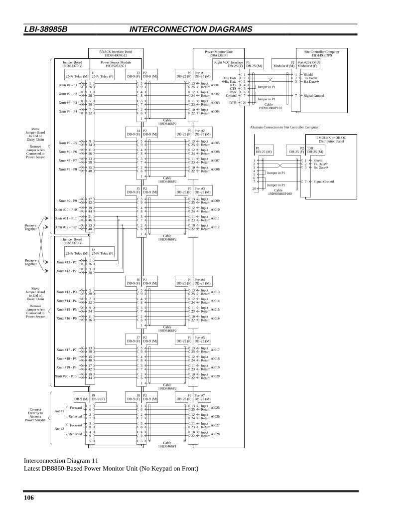
LBI-38985B INTERCONNECTION DIAGRAMS
106
EDACS Interface Panel19D904009G12
Power Sensor Module19C852632G1
J1 J325-Pr Telco (F) DB-9 (F)
126
59
Power Monitor Unit350A1380P1
Port #1
Right VDT Interface
DB-25 (M)
DB-25 (F)
1325
12
P2 P3DB-25 (F)DB-9 (M)
Site Controller Computer19D149302P9
DB-25 (M)P1 P2
Modular 8 (M) Modular 8 (F)Port #29 (PMU)
34567
20
7
123
19D903880P101Cable
188D6466P2Cable
InputReturnAI001
Tx DataRx Data
RTSCTSDSR
DTR
Ground
Xmtr #1 - P1
328
48
1224
InputReturnAI002Xmtr #2 - P2
530
37
1123
InputReturnAI003Xmtr #3 - P3
732
26
1022
InputReturnAI004Xmtr #4 - P4
1
J4DB-9 (F)
Port #2DB-25 (M)
P2 P3DB-25 (F)DB-9 (M)
Cable
934
59
1325
InputReturnAI005Xmtr #5 - P5
1136
48
1224
InputReturnAI006Xmtr #6 - P6
1338
37
1123
InputReturnAI007Xmtr #7 - P7
1540
26
1022
InputReturnAI008Xmtr #8 - P8
1
J5DB-9 (F)
Port #3DB-25 (M)
P2 P3DB-25 (F)DB-9 (M)
Cable
1742
59
1325
InputReturnAI009Xmtr #9 - P9
1944
48
1224
InputReturnAI010Xmtr #10 - P10
2146
37
1123
InputReturnAI011Xmtr #11 - P11
2348
26
1022
InputReturnAI012Xmtr #12 - P12
1
J6DB-9 (F)
Port #4DB-25 (M)
P2 P3DB-25 (F)DB-9 (M)
Cable
530
59
1325
InputReturnAI013Xmtr #13 - P3
732
48
1224
InputReturnAI014Xmtr #14 - P4
934
37
1123
InputReturnAI015Xmtr #15 - P5
1136
26
1022
InputReturnAI016Xmtr #16 - P6
1
J225-Pr Telco (F)
126Xmtr #11 - P1
328Xmtr #12 - P2
J7DB-9 (F)
Port #5DB-25 (M)
P2 P3DB-25 (F)DB-9 (M)
Cable
1338
59
1325
InputReturnAI017
1540
48
1224
InputReturnAI018
1742
37
1123
InputReturnAI019
1944
26
1022
InputReturnAI020
1
Xmtr #17 - P7
Xmtr #18 - P8
Xmtr #19 - P9
Xmtr #20 - P10
J8DB-9 (F)
Port #7DB-25 (M)
P2 P3DB-25 (F)DB-9 (M)
Cable
16
16
1325
InputReturnAI025
27
27
1224
InputReturnAI026
38
38
1123
InputReturnAI027
49
49
1022
InputReturnAI028
5
DB-9 (M)J9DB-9 (F)
5
EMULEX or DILOGDistribution Panel
13B
188D6466P1
188D6466P2
188D6466P2
188D6466P2
188D6466P2
DB-25 (M)DB-25 (F)
ShieldTx DataRx Data
Signal Ground
Alternate Connection to Site Controller Computer:
Forward
Reflected
Reflected
Forward
Ant #1
Ant #2
25-Pr Telco (M)
25-Pr Telco (M)
Jumper Board19C852379G1
Jumper Board19C852379G1
MoveJumper Board
to End ofDaisy Chain
RemoveJumper whenConnected toPower Sensor
MoveJumper Board
to End ofDaisy Chain
RemoveJumper whenConnected toPower Sensor
ConnectDirectly toAntenna
Power Sensors
RemoveTogether
RemoveTogether
12
DB-25 (M)P1 P2
34567
20
7
123
19D903880P100Cable
ShieldTx DataRx Data
Signal Ground
Jumper in P1
Jumper in P1
Jumper in P1
Jumper in P1
Interconnection Diagram 11Latest DB8860-Based Power Monitor Unit (No Keypad on Front)

INTERCONNECTION DIAGRAMS LBI-38985 B
107
EDACS Interface Panel19D904009G12
Power Sensor Module19C852213G1
J1 J325-Pr Telco (F) DB-37 (F)
126
120
DB8843-Based Power Monitor Unit19C336861P1
J5
J8
DB-37 (M)
DB-25 (F)
120
12
P2 P3DB-37 (F)DB-37 (M)
Site Controller Computer19D149302P9
DB-25 (M)P1 P2
Modular 8 (M) Modular 8 (F)Port #29 (PMU)
34567
20
7
123
19D903880P101Cable
19D903880P70Cable
HI
GND
Tx DataRx Data
RTSCTSDSR
DTR
Ground
328
322
221
HIGND
322
HIGND
423
HIGND
1742
1736
1944
2146
2348
J225-Pr Telco (F)
126
328
1540
1742
16
1944
38 P10
J6DB-9 (F)
P2DB-9 (M)
16
16
27
27
38
38
49
49
5
J7DB-9 (M) DB-9 (F)
5
EMULEX or DILOGDistribution Panel
13BDB-25 (M)DB-25 (F)
ShieldTx DataRx Data
Signal Ground
Alternate Connection to Site Controller Computer:
Forward
Reflected
Reflected
Forward
Ant #1
Ant #2
25-Pr Telco (M)
25-Pr Telco (M)
Jumper Board19C852379G1
Jumper Board19C852379G1
MoveJumper Board
to End ofDaisy Chain
RemoveJumper whenConnected toPower Sensor
MoveJumper Board
to End ofDaisy Chain
RemoveJumper whenConnected toPower Sensor
ConnectDirectly toAntenna
Power Sensors
RemoveTogether
RemoveTogether
1736
HI
GND
1837
HIGND
530
524
524
HIGND
625
HIGND
J4DB-37 (F)
P2DB-37 (M)
J6DB-37 (M)
P3DB-37 (F)
19D903880P70Cable
120
120
HI
GND
322
221
HIGND
322
HIGND
423
HIGND
1736
1736
HIGND
1837
HIGND
524
524
HIGND
625
HIGND
J5DB-9 (F)
P2DB-9 (M)
J7DB-25 (M)
P3DB-25 (F)
19D903880P72Cable
322
HIGND
423
HI
GND
524
HIGND
625
HIGND
J4DB-15 (M)
P3DB-15 (F)
19D903880P71Cable
19
HIGND
210
HIGND
311
HIGND
412
HIGND
513
HIGND
614
HIGND
715
HIGND
814
HIGND
Forward
Reflected
Reflected
Reflected
Reflected
Forward
Forward
Forward
Forward
Forward
Reflected
Reflected
Reflected
Reflected
Reflected
Reflected
Reflected
Reflected
Reflected
Reflected
Forward
Forward
Forward
Forward
Forward
Forward
Forward
Forward
Xmtr #20
P9Xmtr #19
P8Xmtr #18
P2Xmtr #12
P1Xmtr #11
P12Xmtr #12
P11Xmtr #11
P10Xmtr #10
P9Xmtr #9
P3Xmtr #3
P2Xmtr #2
P1Xmtr #1
12
DB-25 (M)P1 P2
34567
20
7
123
19D903880P100Cable
ShieldTx DataRx Data
Signal Ground
Jumper in P1
Jumper in P1
Jumper in P1
Jumper in P1
Jumper in P3
Jumper in P3
Jumper in P3
Jumper in P3
Jumper in P3
Jumper in P3
Jumper in P3
Jumper in P3
Jumper in P3
Interconnection Diagram 12 Earlier DB8843-Based PMU (Keypad on Front)

LBI-38985B INTERCONNECTION DIAGRAMS
108
Alarm and Control Unit19D901365G2
J3 J125-Pr Telco DB-25
261 1
2
Site Controller Computer19D149302P9
8-Pin ModularPort #28 (ACU)
34567
20
7
123
19D903880P101Cable
C1 N.O.C1 COM Tx Data
Rx DataRTSCTSDSR
DTR
Ground
27
2
C1 N.C.
283
294
12
EMULEX or DILOGDistribution Panel
DB-2512B
34567
20
7
123
19D903880P100Cable
DB-25
ShieldTx DataRx Data
Signal Ground
ShieldTx DataRx Data
Signal Ground
Earlier Connections to Site Controller Computer:
J2DB-25
12
8-Pin ModularPort #27 (TU)
34567
20
7
123
19D903880P101Cable
Tx DataRx Data
RTSCTSDSR
DTR
Ground
ShieldTx DataRx Data
Signal Ground
Rear Bulkhead Panelwith Harness
19C851141G319D901331G3Interface BoardAlarm / Control
C2 N.O.C2 COMC2 N.C.
C3 N.O.C3 COMC3 N.C.30
12
DB-2511B
34567
20
7
123
19D903880P100Cable
DB-25
ShieldTx DataRx Data
Signal Ground
1137
C8 N.O.C8 COMC8 N.C.12
J425-Pr Telco
261
A1 +A1 C
27
2
A1 G
283
294
A2 +A2 CA2 G
A3 +A3 CA3 G30
2349
A16 +A16 CA16 G24
J525-Pr Telco
261
A17 +A17 C
27
2
A17 G
283
294
A18 +A18 CA18 G
A19 +A19 CA19 G30
2550
+ 13.8 VDC
2349
A32 +A32 CA32 G24
5025 +13.8 VDC
3813
+5 VDC+5 VDC5V GND395V GND14
4015
+13.8 VDC+13.8 VDC13.8V GND4113.8V GND16
See Table
Full Pinoutin Text for
See Table
Full Pinoutin Text for
See Table
Full Pinoutin Text for
Alarm InputConnectionsA17 - A32
Alarm InputConnections
A1 - A16
Control OutputConnections
C1 - C8
a 19B804709P1 Cable is used betweenPort #27 of the Site Controller computer
and J5 of the Orion TU Shelf.
For the Orion TU application,
Jumper in P1
Jumper in P1
Jumper in P1
Jumper in P1
Jumper in P1
Jumper in P1
Jumper in P1
Jumper in P1
P1
P1
P1
P1 P2
P2
P2
P2
13.8V GND
13.8V GND
Interconnection Diagram 13Alarm and Control Unit

INTERCONNECTION DIAGRAMS LBI-38985 B
109
Interconnection Diagram 14 Guardog
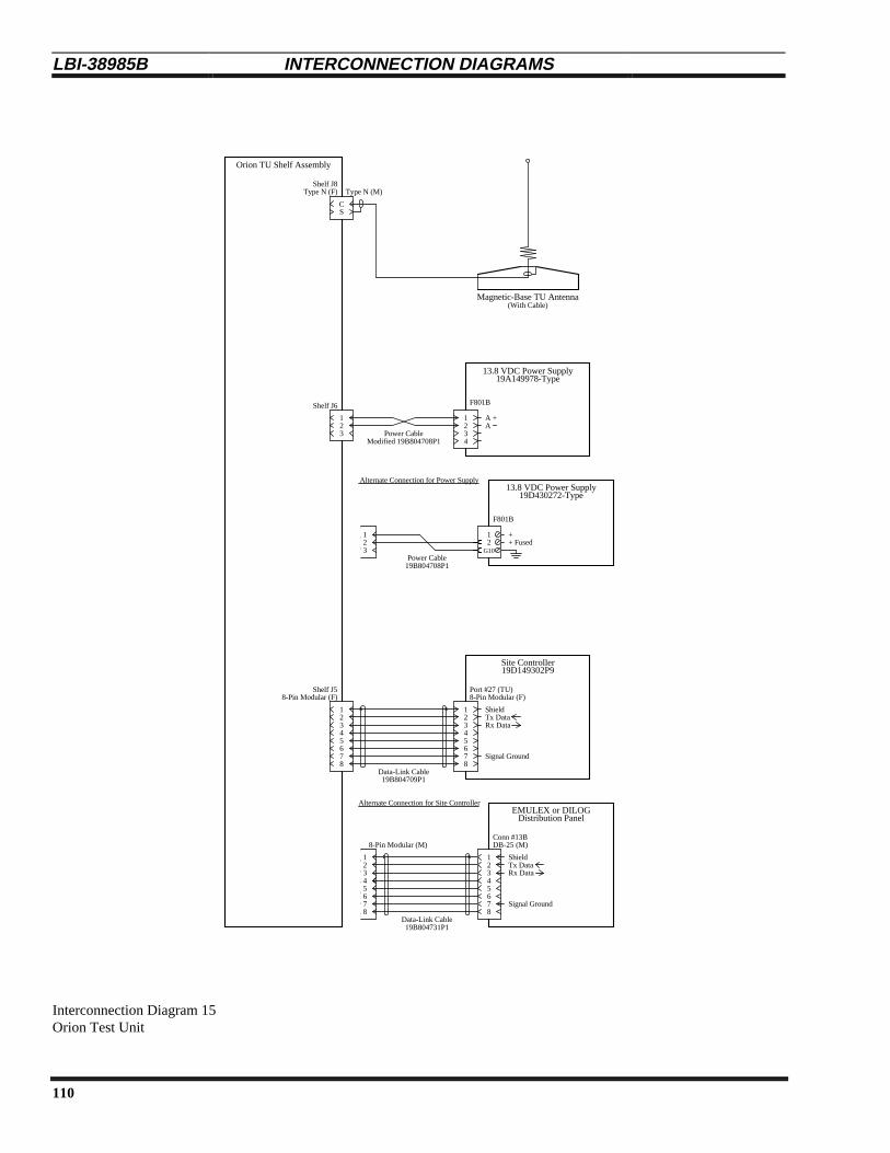
LBI-38985B INTERCONNECTION DIAGRAMS
110
Orion TU Shelf Assembly
Site Controller19D149302P9
8-Pin Modular (F)Port #27 (TU)
19B804709P1Data-Link Cable
EMULEX or DILOGDistribution Panel
Conn #13BDB-25 (M)
ShieldTx DataRx Data
Signal Ground
Alternate Connection for Site Controller
12345678
123
7
123
ShieldTx DataRx Data
Signal Ground
Shelf J5
Shelf J8Type N (M)
SC
F801B
1234
13.8 VDC Power Supply
Magnetic-Base TU Antenna
A +
Power CableModified 19B804708P1
21
13.8 VDC Power Supply
Power Cable
19D430272-Type
19A149978-Type
Alternate Connection for Power Supply
A
45678
8-Pin Modular (M)
56
4
8
19B804708P1
3
Shelf J6
7
123456
8
21
3
Type N (F)
8-Pin Modular (F)
19B804731P1Data-Link Cable
(With Cable)
F801B
12
G10+ Fused+
Interconnection Diagram 15Orion Test Unit
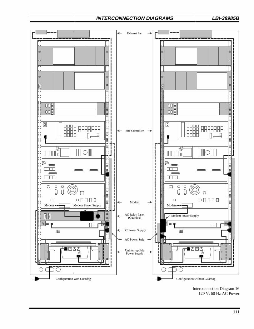
INTERCONNECTION DIAGRAMS LBI-38985 B
111
Site Controller
Modem
Power Supply
DC Power Supply
Uninterruptible
AC Relay Panel(Guardog)
Exhaust Fan
Configuration with Guardog
Modem Modem Power Supply
Configuration without Guardog
Modem
Modem Power Supply
AC Power Strip
Interconnection Diagram 16 120 V, 60 Hz AC Power

LBI-38985B INTERCONNECTION DIAGRAMS
112
Site Controller
Modem
Power Supply
DC Power Supply
Uninterruptible
AC Relay Panel(Guardog)
Exhaust Fan
AC Power Strip
Configuration without Guardog
AC Power Strip
Modem
Configuration with Guardog
AC Power Strip
Modem
Modem Power SupplyModem Power Supply
Interconnection Diagram 17230 V, 50/60 Hz AC Power

INTERCONNECTION DIAGRAMS LBI-38985 B
113
Power Monitor Unit
RIC/LIC Local Interconnect
Downlink GETC
Redundant Downlink GETC
1 125 6 7 8
Alarm & Control Unit
Orion Test Unit Shelf
Modem Shelf
AC Relay Panel
DC Power Supply
TB10
1 6 7 12TB10
J5
J801
J2
J2
J6
P33
2 53 61 4 1 2 3 47 8 9
1 2+
1 3+
19B803255P1
1 3+
19A149357G2
321 +
Modified19B804708P1
F801B
+ 43
Part of Power Monitor Unit
21
#18R #18BK
BKBK
+ +
1 2+ #18BK#18R
+ ++ _ __ _+
#18R
#18R #18BK
#18BK
5A Fuse
#16BK
#16R
#14R#14BK
2
Interconnection Diagram 18 12 VDC Power Distribution

LBI-38985B APPENDIX A
114
APPENDIX ADB8843-BASED PMU
INTRODUCTION
This supplemental information applies only to the19C336861P1 DB8843-based Power Monitor Unit (PMU),shown in Figure A. This supplement includes duplexerapplication, interconnection, power sensor calibration,programming, and troubleshooting information not presentlyincluded in LBI-38985A.
Figure A - Unidirectional Power Sensor
DUPLEXER APPLICATION
If a duplexer is being used, the antenna power sensorMUST be inserted between the transmitter combiner and theduplexer (NOT between the duplexer and the antenna) toavoid the possibility of introducing intermodulation productsinto the receiver.
If a duplexer is being used, the antenna powersensor MUST be inserted between thetransmitter combiner and the duplexer (NOTbetween the duplexer and the antenna).
CAUTION
INTERCONNECTIONS
Connect the PMU as shown in the attachedInterconnection Diagrams. If your system does not haveEDACS Interface Panels, the connections between the PMUand the power sensors will be somewhat different. However,the connection points on the PMU remain the same. Allcabling between power sensors and the PMU must beshielded, and unused PMU inputs must be shorted.
If an EMULEX or DILOG panel is used for theconnections to the Site Controller computer, the connectionto the PMU is shown in Figure B.
Distribution PanelEMULEX / DILOG
123
7
S
1
32
7
19D903880P100Interconnect Cable
13BDB-25 (M)
P2P1
ShieldTx DataRx Data
Signal GND
Connector Shield
56
4
20Jumper in P1
Jumper in P1
DB-25 (M) DB-25 (F)
Figure B - PMU Connection to EMULEX / DILOG Panel
POWER SENSOR CALIBRATION
Each power sensor must be calibrated at the time ofinstallation. It is recommended that each power sensor be re-calibrated every six months thereafter.
The power sensor provides a DC voltage outputrepresenting the power through it. This calibration methoduses an in-line wattmeter to read the power going throughthe power sensor, a DC voltmeter to measure the detectoroutput of the power sensor, and a conversion table tosimulate the PMU’s conversion of this DC voltage to apower measurement. This DC voltage is then adjusted (usingthe 20-turn potentiometer mounted in the power sensor)until the power read from the conversion table agrees withthe power read on the power meter.
Unidirectional Power Sensors
Use the following procedure to calibrate theunidirectional power sensors used at the output of eachtransmitter. Start with the transmitter for channel #1. Thelocation of the calibration screw is shown in Figure C.
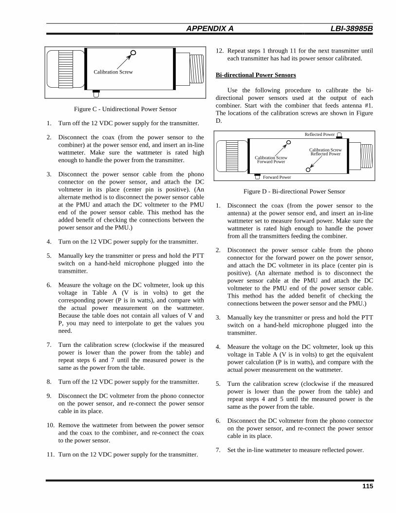
APPENDIX A LBI-38985 B
115
Calibration Screw
Figure C - Unidirectional Power Sensor
1. Turn off the 12 VDC power supply for the transmitter.
2. Disconnect the coax (from the power sensor to thecombiner) at the power sensor end, and insert an in-linewattmeter. Make sure the wattmeter is rated highenough to handle the power from the transmitter.
3. Disconnect the power sensor cable from the phonoconnector on the power sensor, and attach the DCvoltmeter in its place (center pin is positive). (Analternate method is to disconnect the power sensor cableat the PMU and attach the DC voltmeter to the PMUend of the power sensor cable. This method has theadded benefit of checking the connections between thepower sensor and the PMU.)
4. Turn on the 12 VDC power supply for the transmitter.
5. Manually key the transmitter or press and hold the PTTswitch on a hand-held microphone plugged into thetransmitter.
6. Measure the voltage on the DC voltmeter, look up thisvoltage in Table A (V is in volts) to get thecorresponding power (P is in watts), and compare withthe actual power measurement on the wattmeter.Because the table does not contain all values of V andP, you may need to interpolate to get the values youneed.
7. Turn the calibration screw (clockwise if the measuredpower is lower than the power from the table) andrepeat steps 6 and 7 until the measured power is thesame as the power from the table.
8. Turn off the 12 VDC power supply for the transmitter.
9. Disconnect the DC voltmeter from the phono connectoron the power sensor, and re-connect the power sensorcable in its place.
10. Remove the wattmeter from between the power sensorand the coax to the combiner, and re-connect the coaxto the power sensor.
11. Turn on the 12 VDC power supply for the transmitter.
12. Repeat steps 1 through 11 for the next transmitter untileach transmitter has had its power sensor calibrated.
Bi-directional Power Sensors
Use the following procedure to calibrate the bi-directional power sensors used at the output of eachcombiner. Start with the combiner that feeds antenna #1.The locations of the calibration screws are shown in FigureD.
Calibration Screw
Calibration Screw
Forward Power
Reflected Power
Forward Power
Reflected Power
Figure D - Bi-directional Power Sensor
1. Disconnect the coax (from the power sensor to theantenna) at the power sensor end, and insert an in-linewattmeter set to measure forward power. Make sure thewattmeter is rated high enough to handle the powerfrom all the transmitters feeding the combiner.
2. Disconnect the power sensor cable from the phonoconnector for the forward power on the power sensor,and attach the DC voltmeter in its place (center pin ispositive). (An alternate method is to disconnect thepower sensor cable at the PMU and attach the DCvoltmeter to the PMU end of the power sensor cable.This method has the added benefit of checking theconnections between the power sensor and the PMU.)
3. Manually key the transmitter or press and hold the PTTswitch on a hand-held microphone plugged into thetransmitter.
4. Measure the voltage on the DC voltmeter, look up thisvoltage in Table A (V is in volts) to get the equivalentpower calculation (P is in watts), and compare with theactual power measurement on the wattmeter.
5. Turn the calibration screw (clockwise if the measuredpower is lower than the power from the table) andrepeat steps 4 and 5 until the measured power is thesame as the power from the table.
6. Disconnect the DC voltmeter from the phono connectoron the power sensor, and re-connect the power sensorcable in its place.
7. Set the in-line wattmeter to measure reflected power.
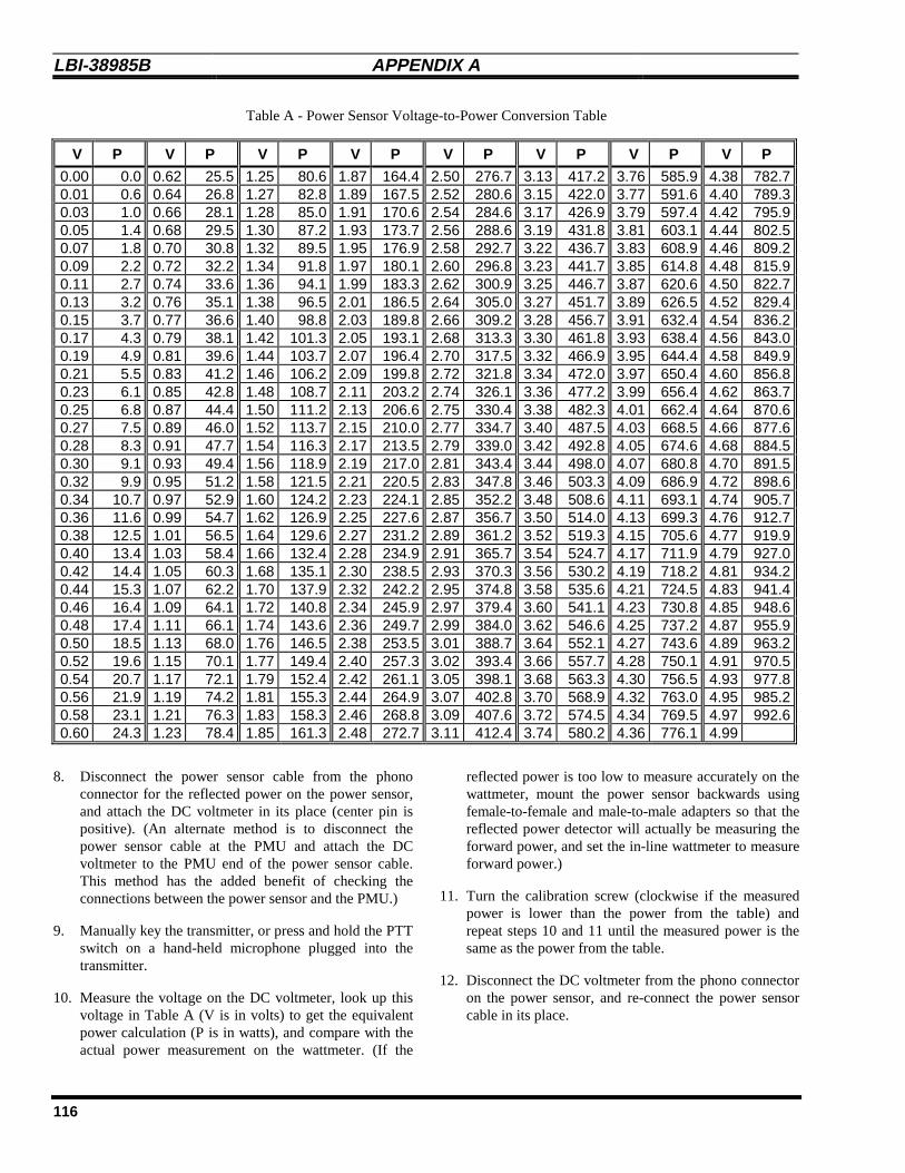
LBI-38985B APPENDIX A
116
Table A - Power Sensor Voltage-to-Power Conversion Table
V P V P V P V P V P V P V P V P
0.00 0.0 0.62 25.5 1.25 80.6 1.87 164.4 2.50 276.7 3.13 417.2 3.76 585.9 4.38 782.70.01 0.6 0.64 26.8 1.27 82.8 1.89 167.5 2.52 280.6 3.15 422.0 3.77 591.6 4.40 789.30.03 1.0 0.66 28.1 1.28 85.0 1.91 170.6 2.54 284.6 3.17 426.9 3.79 597.4 4.42 795.90.05 1.4 0.68 29.5 1.30 87.2 1.93 173.7 2.56 288.6 3.19 431.8 3.81 603.1 4.44 802.50.07 1.8 0.70 30.8 1.32 89.5 1.95 176.9 2.58 292.7 3.22 436.7 3.83 608.9 4.46 809.20.09 2.2 0.72 32.2 1.34 91.8 1.97 180.1 2.60 296.8 3.23 441.7 3.85 614.8 4.48 815.90.11 2.7 0.74 33.6 1.36 94.1 1.99 183.3 2.62 300.9 3.25 446.7 3.87 620.6 4.50 822.70.13 3.2 0.76 35.1 1.38 96.5 2.01 186.5 2.64 305.0 3.27 451.7 3.89 626.5 4.52 829.40.15 3.7 0.77 36.6 1.40 98.8 2.03 189.8 2.66 309.2 3.28 456.7 3.91 632.4 4.54 836.20.17 4.3 0.79 38.1 1.42 101.3 2.05 193.1 2.68 313.3 3.30 461.8 3.93 638.4 4.56 843.00.19 4.9 0.81 39.6 1.44 103.7 2.07 196.4 2.70 317.5 3.32 466.9 3.95 644.4 4.58 849.90.21 5.5 0.83 41.2 1.46 106.2 2.09 199.8 2.72 321.8 3.34 472.0 3.97 650.4 4.60 856.80.23 6.1 0.85 42.8 1.48 108.7 2.11 203.2 2.74 326.1 3.36 477.2 3.99 656.4 4.62 863.70.25 6.8 0.87 44.4 1.50 111.2 2.13 206.6 2.75 330.4 3.38 482.3 4.01 662.4 4.64 870.60.27 7.5 0.89 46.0 1.52 113.7 2.15 210.0 2.77 334.7 3.40 487.5 4.03 668.5 4.66 877.60.28 8.3 0.91 47.7 1.54 116.3 2.17 213.5 2.79 339.0 3.42 492.8 4.05 674.6 4.68 884.50.30 9.1 0.93 49.4 1.56 118.9 2.19 217.0 2.81 343.4 3.44 498.0 4.07 680.8 4.70 891.50.32 9.9 0.95 51.2 1.58 121.5 2.21 220.5 2.83 347.8 3.46 503.3 4.09 686.9 4.72 898.60.34 10.7 0.97 52.9 1.60 124.2 2.23 224.1 2.85 352.2 3.48 508.6 4.11 693.1 4.74 905.70.36 11.6 0.99 54.7 1.62 126.9 2.25 227.6 2.87 356.7 3.50 514.0 4.13 699.3 4.76 912.70.38 12.5 1.01 56.5 1.64 129.6 2.27 231.2 2.89 361.2 3.52 519.3 4.15 705.6 4.77 919.90.40 13.4 1.03 58.4 1.66 132.4 2.28 234.9 2.91 365.7 3.54 524.7 4.17 711.9 4.79 927.00.42 14.4 1.05 60.3 1.68 135.1 2.30 238.5 2.93 370.3 3.56 530.2 4.19 718.2 4.81 934.20.44 15.3 1.07 62.2 1.70 137.9 2.32 242.2 2.95 374.8 3.58 535.6 4.21 724.5 4.83 941.40.46 16.4 1.09 64.1 1.72 140.8 2.34 245.9 2.97 379.4 3.60 541.1 4.23 730.8 4.85 948.60.48 17.4 1.11 66.1 1.74 143.6 2.36 249.7 2.99 384.0 3.62 546.6 4.25 737.2 4.87 955.90.50 18.5 1.13 68.0 1.76 146.5 2.38 253.5 3.01 388.7 3.64 552.1 4.27 743.6 4.89 963.20.52 19.6 1.15 70.1 1.77 149.4 2.40 257.3 3.02 393.4 3.66 557.7 4.28 750.1 4.91 970.50.54 20.7 1.17 72.1 1.79 152.4 2.42 261.1 3.05 398.1 3.68 563.3 4.30 756.5 4.93 977.80.56 21.9 1.19 74.2 1.81 155.3 2.44 264.9 3.07 402.8 3.70 568.9 4.32 763.0 4.95 985.20.58 23.1 1.21 76.3 1.83 158.3 2.46 268.8 3.09 407.6 3.72 574.5 4.34 769.5 4.97 992.60.60 24.3 1.23 78.4 1.85 161.3 2.48 272.7 3.11 412.4 3.74 580.2 4.36 776.1 4.99
8. Disconnect the power sensor cable from the phonoconnector for the reflected power on the power sensor,and attach the DC voltmeter in its place (center pin ispositive). (An alternate method is to disconnect thepower sensor cable at the PMU and attach the DCvoltmeter to the PMU end of the power sensor cable.This method has the added benefit of checking theconnections between the power sensor and the PMU.)
9. Manually key the transmitter, or press and hold the PTTswitch on a hand-held microphone plugged into thetransmitter.
10. Measure the voltage on the DC voltmeter, look up thisvoltage in Table A (V is in volts) to get the equivalentpower calculation (P is in watts), and compare with theactual power measurement on the wattmeter. (If the
reflected power is too low to measure accurately on thewattmeter, mount the power sensor backwards usingfemale-to-female and male-to-male adapters so that thereflected power detector will actually be measuring theforward power, and set the in-line wattmeter to measureforward power.)
11. Turn the calibration screw (clockwise if the measuredpower is lower than the power from the table) andrepeat steps 10 and 11 until the measured power is thesame as the power from the table.
12. Disconnect the DC voltmeter from the phono connectoron the power sensor, and re-connect the power sensorcable in its place.

APPENDIX A LBI-38985 B
117
13. Remove the wattmeter from between the power sensorand the coax to the antenna, and re-connect the coax tothe power sensor.
14. Repeat steps 1 through 13 for the other combiner (if twotransmit antennas are used).
DIP SWITCHES
The DIP Switches recessed into the back of the PMUshould all be set to the OFF position, except switch #5which should be set to the ON position. For slide-type DIPswitches, the OFF position is with the tab pushed down. Forrocker-type DIP switches, the OFF position is with thebottom pushed in.
Table B - DB8843-based PMU Parameters
PARAMETERDESCRIPTION
SITE CONTROLLERCOMPUTER
PERSONALITY PROMS
SYSTEM MANAGERSITE DATABASE
PMUACTIVE CONFIGURATION
Single parameter thatdefines what % of channelsmust fail due to one cause
before the alarms areconsidered bogus.
Channel Fault ToleranceThreshold
(Failure Levels Screen)
Must be enabled here
Parameter set thatenables the PMU option on
a per-channel basis(must also be enabledon a site-wide basis).
Channel PMU Enable(Channel Data screen)
Must be enabled here(set to Y for enabled).
Single parameter thatenables the PMU option on
a site-wide basis(must also be enabled
on a per-channel basis).
Site PMU Enable(PMU screen)
Must be set to On(without System Manager).
Should be set to On(with System Manager).
Power Monitor UnitEnabled
(Site/Device Site TestParameters screen)
Can be enabled here.(set to Y for enabled)
Single parameter thatsets the lower power limit (inwatts) for transmitter output
power.(First non-zero level applies
to all channels.)
PMU Power Levels(PMU screen)
Must be set here(without System Manager orif Site Controller computer
application software islower than G6).
PMU Power Level(Site/Device Site TestParameters screen)
Can be re-configured hereonly if Site Controllercomputer application
software is G6 or higher.
MIN IPF
May temporarily be re-configured here with
different limits for eachchannel.
Single parameter thatdefines the upper SWR limit
for the antenna.
MAX SWR
Can be re-configured herewith different limits for each
antenna.
Antenna Mapping defineswhich antenna is used byeach transmitter channel.
CHNL DESMust be configured here for
each equipped channel.

LBI-38985B APPENDIX A
118
PARAMETERS
The PMU option parameters are shown in Table B. Thefirst column lists the parameters. The next three columnsrepresent the three locations where the parameter must be setor may be re-configured. Parameters may go by slightlydifferent names in different locations.
Channel Fault Tolerance Threshold
This parameter defines what percentage of channelsmust fail due to any combination of causes (i.e. PMU, TestUnit, Carrier, etc.) before the Site Controller computerconsiders those alarms bogus. The Site Controller will findthe alarm type that has failed the most channels, andconsider those alarms to be bogus. This means channelstaken out of service for that alarm type will be brought backinto service. Further failures due to that alarm type will nottake channels out of service, but alarms will continue to bereported to the System Manager and the Alarm & ControlUnit. When all channels are cleared of alarms for that alarmtype, the Site Controller will stop considering alarms of thattype to be bogus. This parameter is only configurable in theSite Controller computer’s Personality PROMs at thefactory. Default is 50 %.
Channel PMU Enable
This parameter set (one bit per channel) is used toenable or disable PMU monitoring of each transmitterchannel on a channel-by-channel basis. It is onlyconfigurable in the Site Controller computer’s PersonalityPROMs at the factory, and must be enabled for each channelyou want the PMU to monitor. It is recommended that all 20channels be enabled (equipped or not).
The factory-configured values for this parameter set inthe Site Controller computer’s Personality PROMs are usedto configure the Site Controller computer’s activeconfiguration during power-up. This parameter set cannot bere-configured in the Site Controller computer’s activeconfiguration by the System Manager. This parameter set issent to the PMU during the EDACS Configuration Setup,but is not re-configurable there either. This parameter set isused by the PMU to determine which transmitter channels tomonitor.
Site PMU Enable
This parameter is used to enable or disable the PMUoption as a whole. It is configured in the Site Controllercomputer’s Personality PROMs by the factory, and can bere-configured in the Site Controller computer’s activeconfiguration from the System Manager (screen 10, page 3).If the system is not equipped with a System Manager, thisparameter must be enabled in the Personality PROMs at thefactory.
The factory-configured value for this parameter in theSite Controller computer’s Personality PROMs is used toinitially configure the Site Controller computer’s activeconfiguration during power-up. The value of this parametermay then be re-configured in the Site Controller computer’sactive configuration through a System Manager. Thisparameter is not sent to (or used by) the PMU. When thisparameter is disabled, the Site Controller computer will notsend poll messages to the PMU.
PMU Low Power Alarm Threshold
This parameter tells the PMU at what power level tobegin alarming. It is configured in the Site ControllerPersonality and can be re-configured in the SystemManager. The value of this parameter must be 10 times thedesired alarm threshold level (in watts), since the PMU willdivide this value by 10. (i.e., if you set the parameter to 100,then the PMU will alarm if the power level is 9.99 watts orless.) See the MIN IPF heading in the Programming section.
MIN IPF
MIN IPF is described under the Programming heading.
MAX SWR
MAX SWR is described under the Programmingheading.
CHNL DES
CHNL DES (Antenna Mapping) is described under theProgramming heading.
PROGRAMMING
At the time of installation you will need to make surethat each required parameter is programmed correctly. If thePMU does not seem to be operating correctly, you shouldclear the memory and re-program each required parameter.The required parameters are described here. (See theDecibel Products manual for optional parameters such asPassword, Time, and Date.)

APPENDIX A LBI-38985 B
119
Memory Clear
Clearing the memory will undo all user-programmingby setting user-configurable parameters to the respectivedefault values. To clear the memory, press the keys on thekeyboard on the front of the PMU as shown in Figure E.
L531 7
KEY SEQUENCE:
C R
Figure E - Memory Clear Sequence
CHNL DES (Antenna Mapping)
Antenna mapping is the assignment of an antennanumber to each of up to twenty transmitter channel numbers.Each equipped transmitter channel number must be mappedto either antenna #1 or Antenna #2. To map antenna #1 tochannel #3, press the keys on the keyboard on the front ofthe PMU as shown in Figure F.
E 010 3 CHNLDES
AnntennaNumber
ChannelNumber
KEY SEQUENCE:
S T ENTR
Figure F - Antenna Mapping Sequence
MIN IPF
The Minimum Input Power Forward parameter is theminimum alarm threshold point for each transmitter’s outputpower. It is used to detect when a transmitter’s forwardpower drops below this power level, indicating a problemwith that specific transmitter. When this minimum level canno longer be reached, a transmitter alarm for this transmitterchannel number is sent to the Site Controller computer.
A value for this parameter is programmed into the SiteController computer’s Personality PROMs in the factory(not field-configurable). Whenever the Site Controllercomputer is turned on or reset, the value of this parameter inthe Personality PROMs is used to configure the SiteController computer’s active configuration. If the SiteController computer’s Application Software PROMs arelabeled 344A3265Gx, and x = 6 or higher, the value of thisparameter can be re-configured in the Site Controllercomputer’s active configuration by the System Manager(PMU Power Level parameter on screen 10, page 3).
However, if x is lower than 6, the value of thisparameter cannot be re-configured in the Site Controllercomputer’s active configuration (it will look like it can, butit can’t). See the PMU Low Power Alarm Threshold headingin the Parameters section.
Regardless of the value of x, the MIN IPF parametermay temporarily be re-configured in the PMU’s activeconfiguration using the keyboard on the front panel. Thistemporary re-configuration lasts until the next time the SiteController computer is powered up, reset, or the PMU isenabled from the System Manager (Power Monitor UnitEnabled parameter on screen 10, page 3).
To program the MIN IPF parameter to a value of 40watts for antenna #1 and channel #3, press the keys on thekeyboard on the front of the PMU as shown in Figure G.The recommended value is 25% of the set output powerlevel for the transmitters. This is because the PMU isdesigned to detect gross power failures. Note that the setoutput power level may be substantially lower than the ratedoutput power for the transmitter, due to system orgovernment limitations.
E 010 3 4 0MINIPF
AnntennaNumber
ChannelNumber
MIN IPF Limit
KEY SEQUENCE:
0
(Power in Watts)
S T ENTR
Figure G - Program Sequence for MIN IPF Parameter
MAX SWR
The Maximum Standing Wave Ratio parameter is themaximum alarm threshold point for each antenna’s inputSWR. It is used to detect when an antenna’s reflected powerincreases above this SWR level, indicating a problem withthat specific antenna. When this maximum ratio value isexceeded, an antenna alarm for this antenna number is sentto the Site Controller computer.
This parameter is not contained in the Site Controllercomputer’s active configuration and therefore can only beprogrammed using the keyboard on the front of the PMU.The recommended value is 2.0, which representsapproximately 11% reflected power.
To program the MAX SWR parameter to a value of 2.0for antenna #1 and channel #3, press the keys on thekeyboard on the front of the PMU as shown in Figure H.
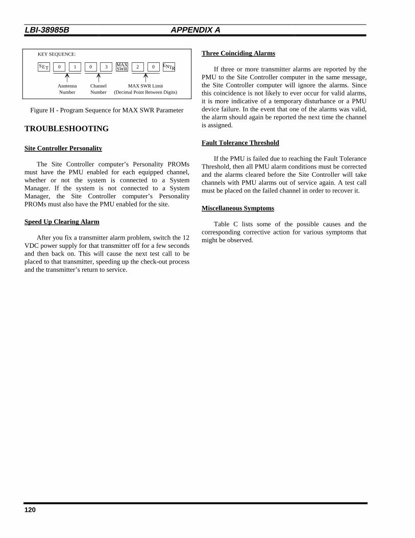
LBI-38985B APPENDIX A
120
E 010 3 0MAXSWR
AnntennaNumber
ChannelNumber
MAX SWR Limit
KEY SEQUENCE:
2
(Decimal Point Between Digits)
S T ENTR
Figure H - Program Sequence for MAX SWR Parameter
TROUBLESHOOTING
Site Controller Personality
The Site Controller computer’s Personality PROMsmust have the PMU enabled for each equipped channel,whether or not the system is connected to a SystemManager. If the system is not connected to a SystemManager, the Site Controller computer’s PersonalityPROMs must also have the PMU enabled for the site.
Speed Up Clearing Alarm
After you fix a transmitter alarm problem, switch the 12VDC power supply for that transmitter off for a few secondsand then back on. This will cause the next test call to beplaced to that transmitter, speeding up the check-out processand the transmitter’s return to service.
Three Coinciding Alarms
If three or more transmitter alarms are reported by thePMU to the Site Controller computer in the same message,the Site Controller computer will ignore the alarms. Sincethis coincidence is not likely to ever occur for valid alarms,it is more indicative of a temporary disturbance or a PMUdevice failure. In the event that one of the alarms was valid,the alarm should again be reported the next time the channelis assigned.
Fault Tolerance Threshold
If the PMU is failed due to reaching the Fault ToleranceThreshold, then all PMU alarm conditions must be correctedand the alarms cleared before the Site Controller will takechannels with PMU alarms out of service again. A test callmust be placed on the failed channel in order to recover it.
Miscellaneous Symptoms
Table C lists some of the possible causes and thecorresponding corrective action for various symptoms thatmight be observed.

APPENDIX A LBI-38985 B
121
Table C - Troubleshooting Symptoms
SYMPTOM POSSIBLE CAUSE(S) CORRECTIVE ACTION
All antenna alarm symptoms. Power sensor is defective or needscalibration.
Replace and/or calibrate powersensor. See Power SensorCalibration.
PMU input circuit is defective. Apply dc voltage (negative ground)to power sensor end of cable toPMU (see Table A for voltage tosimulate normal power levels). Ifalarm remains, cable or PMU inputis defective.
Wattmeter is reading incorrectly. Repair and/or calibrate wattmeter.
Constant antenna alarm for oneantenna, but forward and reflectedpower reads OK on wattmeter.
MAX SWR alarm limit is set toolow.
Program MAX SWR alarm limit tohigher value. See Programming.
Antenna power sensor cable isdefective or connected incorrectly.
Check continuity of cable fromantenna power sensor to PMU. Seeinterconnection diagram in LBI.
Occasional antenna alarm for oneantenna, but forward and reflectedpower reads OK on wattmeter.
MAX SWR alarm limit is set toolow.
Program MAX SWR alarm limit tohigher value. See Programming.
Power from adjacent antennabeing measured as reflected power.
Program MAX SWR alarm limit tohigher value. See Programming.
Disable SWR measurements (byunplugging and jumpering the cableto the reflected power sensorcircuit).
Move antenna(s) to reducecoupling.
No antenna alarm for one antenna,but reflected power reads too highon wattmeter.
MAX SWR alarm limit is set toohigh.
Program MAX SWR alarm limit tolower value. See Programming.
Antenna power sensor cable isdefective or connected incorrectly.
Check continuity of cable fromantenna power sensor to PMU. Seeinterconnection diagram in LBI.
All transmitter alarm symptoms. Transmitter power sensor isdefective or needs calibration.
Replace and/or calibrate powersensor. See Power SensorCalibration.
PMU input circuit is defective. Apply dc voltage (negative ground)to power sensor end of cable toPMU (see Table A for voltage tosimulate normal power levels). Ifalarm remains, cable or PMU inputis defective.
Wattmeter is reading incorrectly. Repair and/or calibrate wattmeter.
(Continued)

LBI-38985B APPENDIX A
122
Table C - Troubleshooting Symptoms (Continued)
SYMPTOM POSSIBLE CAUSE(S) CORRECTIVE ACTION
Constant transmitter alarm forone or more transmitters, buttransmitters’ power reads OK onwattmeter.
MIN IPF alarm limit is set too high. Program MIN IPF alarm limit tolower value. See Programming.
Transmitter power sensor cableis defective or connectedincorrectly.
Check continuity of cable fromtransmitter power sensor to PMU.See interconnection diagram in LBI.
Occasional transmitter alarm forone or more transmitters, buttransmitters’ power reads OK onwattmeter.
MIN IPF alarm limit is set too high. Program MIN IPF alarm limit tolower value. See Programming.
No transmitter alarm for onetransmitter, but forward powerreads too low on wattmeter.
MIN IPF alarm limit is set too low. Program MIN IPF alarm limit tohigher value. See Programming.
Transmitter power sensor cableis defective or connectedincorrectly.
Check continuity of cable fromtransmitter power sensor to PMU.See interconnection diagram in LBI.
No transmitter alarm , even aftertransmitter’s power sensor cable isdeliberately disconnected and call isplaced on transmitter.
Channel is not PMU enabled inSite Controller computer’sPersonality PROMs.
Replace Site Controller computer’sPersonality PROMs with set thathas all equipped transmitterchannels PMU enabled.
MIN IPF alarm limit has beenprogrammed in PMU to zero wattsfor this transmitter channel.
Program MIN IPF alarm limit to non-zero value. See Programming.
No transmitter alarm , even whenall cables between transmitterpower sensors and PMU aredeliberately disconnected.
MIN IPF alarm limit is set to zero. Program MIN IPF alarm limit to non-zero value. See Programming.
Site is not PMU enabled in SiteController computer’s PersonalityPROMs or from System Manager.
Enable PMU from System Manager,or replace Site Controllercomputer’s Personality PROMs withset that has site PMU enabled.
Transmitter alarm is reported toSystem Manager, channel is turnedoff from Site ReconfigurationChannel screen in SystemManager, transmitter isn’t fixed,channel is turned back on,transmitter alarm is still reported,and yet channel is being assignedto calls.
Channel fault tolerance thresholdwas exceeded. When channel wasturned off from System Manager,number of total channels wasreduced by one, causing quantity offailed channels as % of totalchannels to exceed threshold andassign previously failed PMUchannels. This is most likely tohappen if the total number ofchannels is small.
Check System Manager screen #40(Alarm Control Display) to see if a ♦is shown to the right of Power Mntrindicating that channel faulttolerance threshold has beenexceeded. If so, increase thresholdor fix transmitter.
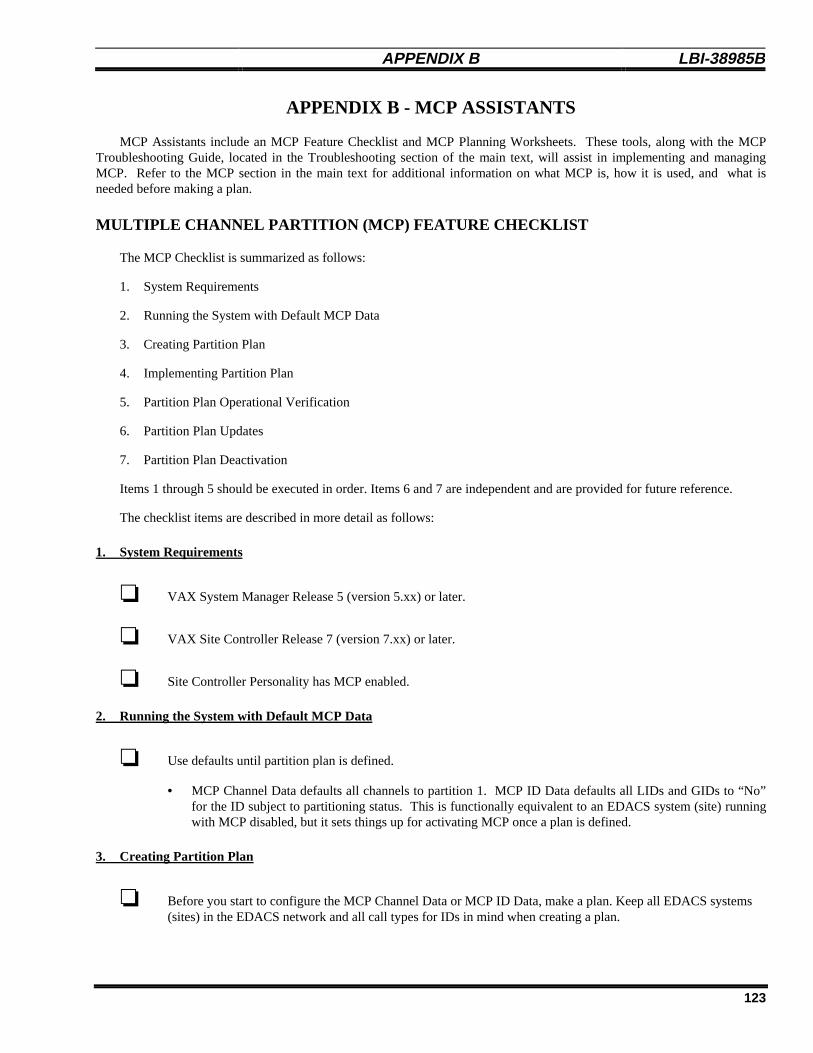
APPENDIX B LBI-38985 B
123
APPENDIX B - MCP ASSISTANTS
MCP Assistants include an MCP Feature Checklist and MCP Planning Worksheets. These tools, along with the MCPTroubleshooting Guide, located in the Troubleshooting section of the main text, will assist in implementing and managingMCP. Refer to the MCP section in the main text for additional information on what MCP is, how it is used, and what isneeded before making a plan.
MULTIPLE CHANNEL PARTITION (MCP) FEATURE CHECKLIST
The MCP Checklist is summarized as follows:
1. System Requirements
2. Running the System with Default MCP Data
3. Creating Partition Plan
4. Implementing Partition Plan
5. Partition Plan Operational Verification
6. Partition Plan Updates
7. Partition Plan Deactivation
Items 1 through 5 should be executed in order. Items 6 and 7 are independent and are provided for future reference.
The checklist items are described in more detail as follows:
1. System Requirements
❏ VAX System Manager Release 5 (version 5.xx) or later.
❏ VAX Site Controller Release 7 (version 7.xx) or later.
❏ Site Controller Personality has MCP enabled.
2. Running the System with Default MCP Data
❏ Use defaults until partition plan is defined.
• MCP Channel Data defaults all channels to partition 1. MCP ID Data defaults all LIDs and GIDs to “No”for the ID subject to partitioning status. This is functionally equivalent to an EDACS system (site) runningwith MCP disabled, but it sets things up for activating MCP once a plan is defined.
3. Creating Partition Plan
❏ Before you start to configure the MCP Channel Data or MCP ID Data, make a plan. Keep all EDACS systems(sites) in the EDACS network and all call types for IDs in mind when creating a plan.

LBI-38985B APPENDIX B
124
A. MCP Channel Data
❏ For each system in the network that is enabled for MCP, the MCP Channel Data must be set up.
• At least one partition must always be defined at the site.
• A highly partitioned system may result in a high call queuing rate.
• Channel partitioning is done on a per site basis. The partition number assigned to a specific channel numberat one site does not need to be the same as the partition number assigned to the same channel number atanother site, particularly when the number of channels varies from site to site.
❏ The RF field still defines which channels are enabled for the site.
B. Allowed Control Channel Management
❏ The Active Control Channel (ACC) partition should contain a sufficient number of channels to handle MCPassignments. These assignments include calls between IDs having different partition designations, calls for IDsthat are not MCP enabled, and calls for IDs with the primary partition number of the ACC. Coverage area, calltype, and quantity of channels should all be taken into consideration when setting up the ACC partition.
❏ When specifying the allowed control channels (Allowed CC on the System Manager), use the fewest number ofMCP partitions needed to provide adequate CC movement per customer requirements. This maximizes partitionuse for calls per the partition plan.
C. MCP ID Data
❏ For each GID and/or LID in the System Manager database that is subject to partitioning, MCP ID Data must beset up.
• GID and LID partitioning is currently done on a network wide basis (all sites).
❏ The ID Subject to Partitioning field in the LID and GID database screens indicate whether or not the ID is MCPenabled ” yes” or disabled “no”. If the ID is not subject to partitioning, the ACC partition will be used.
❏ The Primary Partition field in the LID and GID database screens designates the partition of choice (where thecall should be assigned) under typical system conditions.
❏ The Optional Backup Partition fields in the LID and GID database screens will indicate the condition for usingthis partition when the primary partition is unavailable and the partition number assigned to that backup. Thesite will search these backup partitions in ascending numerical order.
4. Implementing Partition Plan
❏ Once you have created a plan, you can start to configure the site(s) with MCP Channel Data and MCP ID Data.
❏ Perform a System Manager Database Backup to establish a non-MCP baseline.

APPENDIX B LBI-38985 B
125
A. Entering MCP Channel and ID Data
• Note there are three options given here as to how the partition plan can be entered. The difference among theoptions is the impact that MCP will have on system operation versus the ease in entering the data. As aguideline, option 2 is recommended.
The issue is as follows: once the MCP Data is entered, but before you are ready to update the site with the data,the Site Controller may get reset (e.g., power outage). If this happens, the (perhaps partial) MCP Data that hasbeen entered will update the site. This will consequently affect system operation (i.e., If the Channel Data hasbeen entered but no ID Data, then all calls will go to the ACC partition. This could cause calls to get queued ifthe ACC is not large enough to handle all system activity.)
Since the likelihood of the Site Controller being reset may vary from system to system, these three options giveyou the ability to enter the MCP Data in the manner that will suit your particular needs (whether they be ease inentering or safety from the Site Controller being reset).
Note that Channel Data must be entered for all sites before ID Data is entered. ID Data is configured on anetwork wide basis, it will update all MCP enabled sites in the network with this information. Since ChannelData is configured on a per site basis, all MCP enabled sites must be configured with their Channel Databefore the ID Data is entered.
Option 1 - Quick Data Entry (with potentially high Site Controller reset impact):
❏ This option is useful for the following scenarios:
• Small partition plans
• Low call activity
• System installation (where the system and/or network is not yet on-line)
This option provides the easiest method of entering the MCP Data, but it is subject to operational risk if the SiteController is reset before all data is entered. If there is relatively low risk that the Site Controller will be resetbefore all data is entered and this process is taking place during a very low call activity period, then this optionis most likely the best one for you.
I) Enter and save the MCP Channel Data in the System Manager Site Definition Screen (screen 10) for all MCPenabled sites. Do not update the site(s) with the MCP Channel Data at this time. Channel Data must be enteredbefore MCP ID Data. If MCP ID Data is entered before MCP Channel Data and the site(s) gets updated withthe data (i.e., site is reset), then calls made to and from MCP enabled IDs may be denied (since there are notchannels assigned to any other partition but 1).
ii) Enter and save all of the MCP GID Data (enable the ID and set up the primary and backup partitioninformation) in the System Manager Group Definition Screen (screen 12). When entering the data, do it by MCPprimary partition (i.e., enter MCP Data for all GIDs with primary partition 1 first, then for all GIDs with primarypartition 2, then with primary partition 3, etc.) Do not update the site(s) with the MCP GID Data at this time.
iii) Enter and save all of the MCP LID Data (enable the ID and set up the primary and backup partition information)in the System Manager Logical Unit Definition Screen (screen 11). When entering the data, do it by MCPprimary partition (i.e., enter MCP Data for all LIDs with primary partition 1 first, then for all LIDs with primarypartition 2, then with primary partition 3, etc.) Do not update the site(s) with the MCP LID Data at this time.
iv) Create the following System Manager reports and verify that the MCP Data is correct:

LBI-38985B APPENDIX B
126
• Device Report (screen 60)
• Logical Unit Report (screen 61)
• Group Report (screen 62)
Option 2 - Partition-based Data Entry (with low Site Controller reset impact):
❏ This option is recommended for general use. It is useful for the following scenarios:
• Large partition plans
• High call activity
• Low tolerance to Site Controller reset scenario
This option provides a more difficult method of entering the MCP Data, but with almost no impact if the SiteController is reset before all data is entered. If there is a real risk that the Site Controller will be reset before alldata is entered or this process is taking place during a very high call activity period which may cause queuing,then this option is most likely the best one for you.
i) Enter and save the MCP Channel Data for one of the partitions from the partition plan (we’ll call this partition X- screen 10). Do this for all MCP enabled sites. Do not update the site(s) with the MCP Channel Data at thistime.
ii) Enter and save the MCP GID primary and backup partition information for those GIDs that will have a primarypartition of X. Do not update the site(s) with the MCP GID Data at this time.
iii) Enter and save the MCP LID primary and backup partition information for those LIDs that will have a primarypartition of X. Do not update the site(s) with the MCP LID Data at this time.
iv) For those GIDs that will have a primary partition of X, enable them for MCP and save. Do not update thesite(s) with the MCP GID Data at this time.
v) For those LIDs that will have a primary partition of X, enable them for MCP and save. Do not update the site(s)with the MCP LID Data at this time.
vi) Repeat steps i through v until all MCP Data for all partitions from the partition plan has been entered and savedfor all sites.
vii) Create the following System Manager reports and verify that the MCP Data is correct:
• Device Report (screen 60)
• Logical Unit Report (screen 61)
• Group Report (screen 62)
Option 3 - Phased Data Entry (with Delayed Activation):
❏ This option is useful for the following scenarios:
• System installation (where turn on of MCP is delayed, and partition planning definition phase may be done onSystem Manager)

APPENDIX B LBI-38985 B
127
This option provides a compromise between the ease of entering the MCP Data and safety from the SiteController being reset. If there is a minimal risk that the Site Controller will be reset before all data is enteredbut this process is taking place during a very high call activity period, then this option is most likely the best onefor you.
This procedure is executed in two phases, which will require two passes through the ID databases.
Phase I (prior to Site Controller turn-on):
I-i) Enter and save the MCP Channel Data in the System Manager Site Definition Screen (screen 10) for allMCP enabled site(s). Do not update the site(s) with the MCP Channel Data at this time. Channel Datamust be entered before MCP ID Data. If MCP ID Data is entered before MCP Channel Data and the site(s)gets updated with the data (i.e., Site Controller is reset), then calls made to and from MCP enabled IDs maybe denied (since there are not channels assigned to any other partition but 1).
I-ii) Enter and save the MCP GID primary and backup partition information for all GIDs. This is done in theSystem Manager Group Definition Screen (screen 12). When entering the data, do it by MCP primarypartition (i.e., enter MCP Data for all GIDs with primary partition 1 first, then for all GIDs with primarypartition 2, then with primary partition 3, etc.) Do not update the site with the MCP GID Data at this time.
I-iii)Enter and save all of the MCP LID primary and backup partition information for all LIDs. This is done inthe System Manager Logical Unit Definition Screen (screen 11). When entering the data, do it by MCPprimary partition (i.e., enter MCP Data for all LIDs with primary partition 1 first, then for all LIDs withprimary partition 2, then with primary partition 3, etc.) Do not update the site with the MCP LID Data atthis time.
Phase II (sometime after system is on-line):
II-i) For those GIDs changed in step ii, enable them for MCP and save (screen 12). Do not update the site withthe MCP GID Data at this time.
II-ii)For those LIDs changed in step iii, enable them for MCP and save (screen 11). Do not update the site withthe MCP LID Data at this time.
II-iii)Create the following System Manager reports and verify that the MCP Data is correct:
• Device Report (screen 60)
• Logical Unit Report (screen 61)
• Group Report (screen 62)
B. Activate Partition Plan
❏ Update each MCP enabled site with the MCP Channel Data using the System Manager Site ReconfigurationScreen, Channel (screen 20). Note that Channel Data is entered on a per site basis where ID Data is enteredfor all sites. This means all sites must be updated before updating the site with the MCP ID Data.
❏ Update the system with the MCP ID Data using the System Manager Device Communication, Database UploadScreen (screen 30). Simply mark the Full Logical ID Database and Full Group ID Database fields with a “Y”and submit your request. Note that all sites will be updated at once. This should be done after updating allMCP enabled systems with MCP Channel Data.
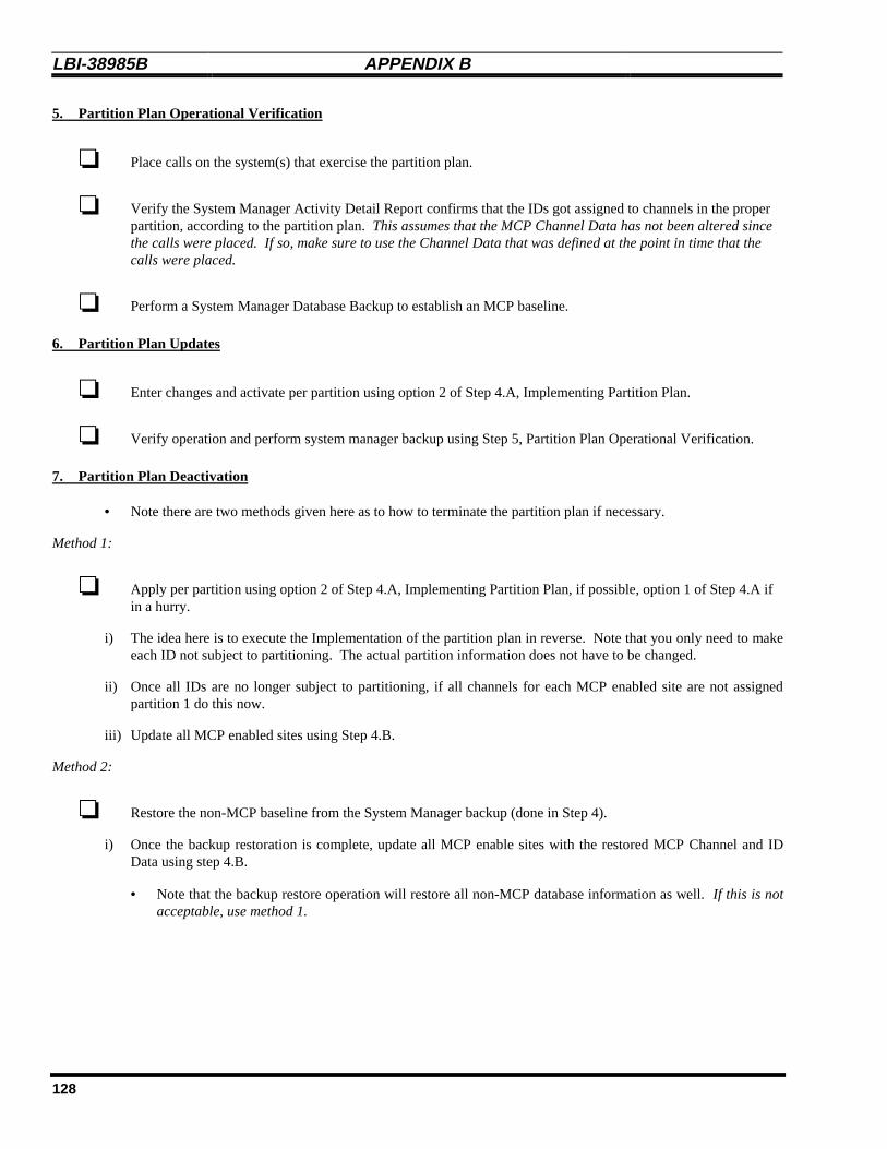
LBI-38985B APPENDIX B
128
5. Partition Plan Operational Verification
❏ Place calls on the system(s) that exercise the partition plan.
❏ Verify the System Manager Activity Detail Report confirms that the IDs got assigned to channels in the properpartition, according to the partition plan. This assumes that the MCP Channel Data has not been altered sincethe calls were placed. If so, make sure to use the Channel Data that was defined at the point in time that thecalls were placed.
❏ Perform a System Manager Database Backup to establish an MCP baseline.
6. Partition Plan Updates
❏ Enter changes and activate per partition using option 2 of Step 4.A, Implementing Partition Plan.
❏ Verify operation and perform system manager backup using Step 5, Partition Plan Operational Verification.
7. Partition Plan Deactivation
• Note there are two methods given here as to how to terminate the partition plan if necessary.
Method 1:
❏ Apply per partition using option 2 of Step 4.A, Implementing Partition Plan, if possible, option 1 of Step 4.A ifin a hurry.
i) The idea here is to execute the Implementation of the partition plan in reverse. Note that you only need to makeeach ID not subject to partitioning. The actual partition information does not have to be changed.
ii) Once all IDs are no longer subject to partitioning, if all channels for each MCP enabled site are not assignedpartition 1 do this now.
iii) Update all MCP enabled sites using Step 4.B.
Method 2:
❏ Restore the non-MCP baseline from the System Manager backup (done in Step 4).
i) Once the backup restoration is complete, update all MCP enable sites with the restored MCP Channel and IDData using step 4.B.
• Note that the backup restore operation will restore all non-MCP database information as well. If this is notacceptable, use method 1.

APPENDIX B LBI-38985 B
129
MULTIPLE CHANNEL PARTITION (MCP) PLANNING WORKSHEETS
MCP Template: Channel Data
Site Definition - Channel Configuration Partitioning
This template is an extract from the System Manager screen 10 (panel 1.4). Use this as a guide to setupeach site that is MCP enabled.
Device Number : ________
Channel Configuration:1 2 3 4 5 6 7 8 9 10 11 12 13 14 15 16 17 18 19 20 21 22 23 24
RF:
__ __ __ __ __ __ __ __ __ __ __ __ __ __ __ __ __ __ __ __ __ __ __ __
Allowed CC:
__ __ __ __ __ __ __ __ __ __ __ __ __ __ __ __ __ __ __ __ __ __ __ __
MC Partition:
__ __ __ __ __ __ __ __ __ __ __ __ __ __ __ __ __ __ __ __ __ __ __ __
Legend:
RF: Enter ‘Y’ for enabled, ‘N’ for disabled, and ‘C’ for the control channel.
Allowed CC: Enter ‘Y’ if the channel is allowed to be a control channel and ‘N’ if it is not.
MC Partition: Enter the character (1-9 for partitions 1-9 and A-F for partitions 10-15) for the partition that should be assigned to the channel.
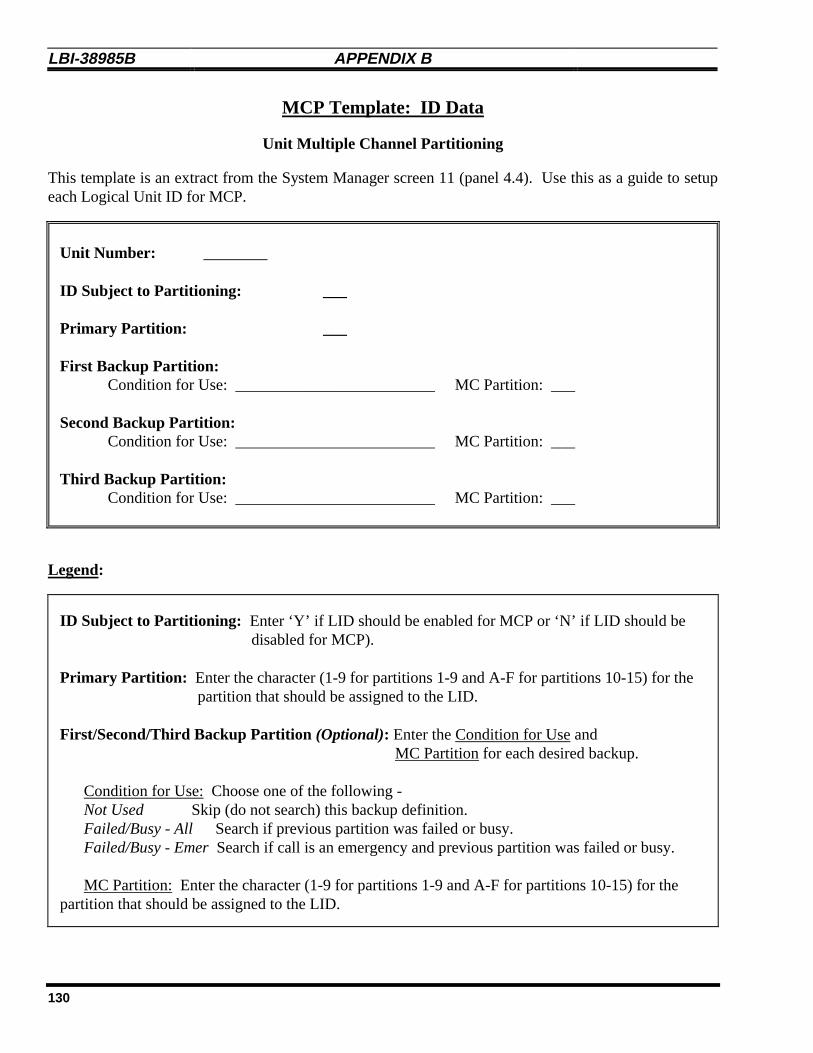
LBI-38985B APPENDIX B
130
MCP Template: ID Data
Unit Multiple Channel Partitioning
This template is an extract from the System Manager screen 11 (panel 4.4). Use this as a guide to setupeach Logical Unit ID for MCP.
Unit Number: ________
ID Subject to Partitioning: ___
Primary Partition: ___
First Backup Partition:Condition for Use: _________________________ MC Partition: ___
Second Backup Partition:Condition for Use: _________________________ MC Partition: ___
Third Backup Partition:Condition for Use: _________________________ MC Partition: ___
Legend:
ID Subject to Partitioning: Enter ‘Y’ if LID should be enabled for MCP or ‘N’ if LID should bedisabled for MCP).
Primary Partition: Enter the character (1-9 for partitions 1-9 and A-F for partitions 10-15) for thepartition that should be assigned to the LID.
First/Second/Third Backup Partition (Optional): Enter the Condition for Use andMC Partition for each desired backup.
Condition for Use: Choose one of the following -Not Used Skip (do not search) this backup definition.Failed/Busy - All Search if previous partition was failed or busy.Failed/Busy - Emer Search if call is an emergency and previous partition was failed or busy.
MC Partition: Enter the character (1-9 for partitions 1-9 and A-F for partitions 10-15) for thepartition that should be assigned to the LID.
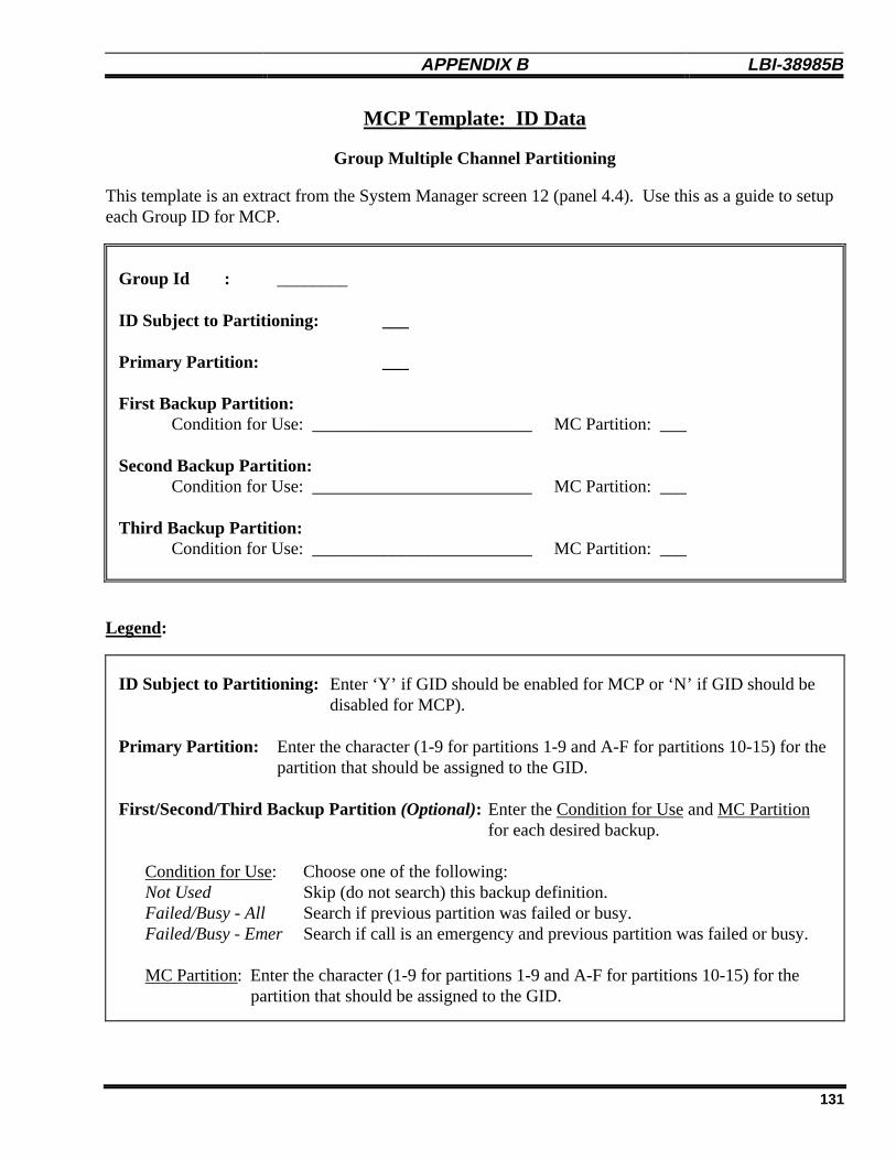
APPENDIX B LBI-38985 B
131
MCP Template: ID Data
Group Multiple Channel Partitioning
This template is an extract from the System Manager screen 12 (panel 4.4). Use this as a guide to setupeach Group ID for MCP.
Group Id : ________
ID Subject to Partitioning: ___
Primary Partition: ___
First Backup Partition:Condition for Use: _________________________ MC Partition: ___
Second Backup Partition:Condition for Use: _________________________ MC Partition: ___
Third Backup Partition:Condition for Use: _________________________ MC Partition: ___
Legend:
ID Subject to Partitioning: Enter ‘Y’ if GID should be enabled for MCP or ‘N’ if GID should bedisabled for MCP).
Primary Partition: Enter the character (1-9 for partitions 1-9 and A-F for partitions 10-15) for thepartition that should be assigned to the GID.
First/Second/Third Backup Partition (Optional): Enter the Condition for Use and MC Partitionfor each desired backup.
Condition for Use: Choose one of the following:Not Used Skip (do not search) this backup definition.Failed/Busy - All Search if previous partition was failed or busy.Failed/Busy - Emer Search if call is an emergency and previous partition was failed or busy.
MC Partition: Enter the character (1-9 for partitions 1-9 and A-F for partitions 10-15) for thepartition that should be assigned to the GID.

LBI-38985B
Ericsson Inc.Private Radio SystemsMountain View RoadLynchburg, Virginia 245021-800-528-7711 (Outside USA, 804-528-7711) Printed in U.S.A.