layerwise finite element piezoelasticity analysis of...
TRANSCRIPT

1
*Corresponding author: Tel.: +983133915214., Email address: [email protected] (M.
Javanbakht)
Layerwise finite element piezoelasticity analysis of functionally graded shell panel
integrated with piezoelectric actuator and sensor
Mahdi Javanbakht1*
and Mohammad Mohammadian1
1Department of Mechanical Engineering, Isfahan University of Technology, Isfahan 84156-
83111, Iran
In the present study, a layerwise finite element method is utilized to solve the coupled elasticity
and piezoelectricity equations to study a functionally graded shell panel integrated with
piezoelectric layers under electromechanical loading. The system of equations is reduced to
ordinary differential equations with variable coefficients by means of trigonometric function
expansion in circumferential and longitudinal directions satisfying mechanical and electrical
boundary conditions. These equations are solved using the Galerkin FEM and Newmark method.
The results of stress, displacement and electrical potential are presented and the effect of panel
thickness and applied voltage on the structural behavior is investigated.
Keywords: finite element; piezoelectric; functionally graded; elasticity
1. Introduction
In recent years, smart materials have been broadly used in many smart structures and
systems. Piezoelectric as one of the most common smart materials has been used as sensor for
monitoring and as actuator for controlling the response of structures [1-7] due to its coupled
mechanical and electrical properties. In comparison with other smart materials, piezoelectric
reveals some important advantages such as high accuracy, generation of large forces and very
fast response. Hence, piezoelectric characteristics have been of great interest and a lot of works
have been devoted to investigate its different properties in different size scales [8-13].

2
On the other hand, functionally graded materials (FGMs) are composite materials,
microscopically inhomogeneous, in which their mechanical properties continuously vary from
one surface to the other [14]. FGMs have many applications in aerospace, nuclear reactors,
chemical plants and turbines. More importantly, they are promising candidates for smart
composites having special arrangements of layers made of various materials to display favorite
characteristics [15]. Therefore, the integration of piezoelectric materials and functionally graded
materials has become an important subject in the area of smart materials and structures and many
attempts have been dedicated to investigate different structures including piezoelectric materials
and functionally graded materials under different conditions.
An analytical solution for functionally graded piezoelectric laminates was suggested in [16] in
which the equations are developed in terms of a Stroh-like formalism assuming that the
mechanical and electric properties of the material have the same exponent-law dependence on
the thickness-coordinate. An analytical approach was presented in [17] for free vibrations and
dynamic responses of a simply supported functionally graded doubly curved shell integrated with
functionally graded piezoelectric layers, particularly using the Hamilton’s principle and the third
order shear deformation theory of shells. The general theoretical analysis for a hollow cylinder
made of functionally graded piezoelectric material subjected to two-dimensional
electromechanical load was developed in [18]. The method of solution was based on the direct
method and by using the complex Fourier series, the Navier equations were solved. An analytical
approach for free vibration and dynamic response of simply supported functionally graded
piezoelectric cylindrical panels subjected to impulsive loads was suggested in [19]. Using the
Hamilton’s principle, the equations of motion based on the first-order shear deformation theory
(FSDT) were derived and the Maxwell’s electricity equation was taken as one of the governing
equations. An analytical investigation was presented [20] for the nonlinear dynamic analysis and
vibrations of imperfect FG thick double curved shallow shells with piezoelectric actuators on
elastic foundations subjected to the combination of electrical, thermal, mechanical and damping
loadings. The theory of plates and shells coupled with the piezoelectricity theory were applied to
functionally graded piezoelectric sensor and actuator [21]. Behjat et al. [22] studied static
bending, free vibration and dynamic responses of FG piezoelectric cylindrical panels subjected
to mechanical, thermal and electrical loadings using the FSDT and the FEM. A three-
dimensional elasticity solution for static analysis of a simply supported FG cylindrical panel

3
integrated with piezoelectric layers under normal load and electric excitation was presented in
[23]. The static bending, free vibration and transient responses of functionally graded
piezoelectric plates under mechanical and electrical loads were investigated in [24] based on the
FSDT, Hamilton’s principle and the FEM. The FEM of functionally graded plates integrated
with piezoelectric patches was presented in [25]. Dynamic analysis of functionally graded
piezoelectric shell panel based on the three-dimensional elasticity theory was presented in
[26,27]. Functionally graded shallow and non-shallow shell panels with piezoelectric layers were
studied under mechanical loading and electrostatic excitation [28]. Functionally graded and
layered magneto-electro-elastic plates and shells were studied [29] using a semi-finite element
method so that a series solution was assumed in the plane of the plate and the finite element
procedure was adopted across the thickness of the plate. Also, FG shells were analyzed using a
layerwise model in which cylindrical shells were assumed to include many homogeneous sub
cylinders [30]. Huang used a higher order shear deformation theory (HSDT) and the general von
Karman equation to formulate the governing equations of a FG plate with thermo-piezo- electric
effects under thermo-electro loading [31]. The refined plate theory (RPT) has been applied to FG
plates with piezoelectric layers for free vibration analysis [32]. Three dimensional piezo-
elasticity and the FEM were used to analyze a functionally graded plate integrated with two
piezoelectric layers under electromechanical loading [33]. Nonlinear dynamic response of a
piezoelastic FG plate with piezoelectric sensor and actuator was investigated [34] by establishing
the nonlinear dynamic equations of the piezoelectric FG plate. The differential quadrature
method (DQM) was utilized for a three-dimensional thermo-elastic analysis of a functionally
graded cylindrical shell with piezoelectric layers [35]. Dynamic analysis of shallow doubly
curved FG panels integrated with sensor/actuator piezoelectric layers was analytically
investigated [36]. The total potential energy was derived based on the modified Sander’s shell
theory combined with the FSDT. The governing equations were established based on the
Reddy’s HSDT that include thermo-piezoelectric effects. By applying the Galerkin method,
Runge–Kutta method and using stress function, natural frequencies and dynamic response of FG
hybrid shells were determined. A thin plate theory based finite element formulation was
suggested by He et al. [37] to control the shape and vibration of a FG plate with integrated
piezoelectric sensors and actuators under mechanical loading. Vibration analysis of functionally
graded piezoelectric plates was studied in [38]. Thermo-electro-elastic analysis of functionally

4
graded piezoelectric shells was presented in [39]. Jafari and coworkers [40] analyzed the
nonlinear vibrations of simply supported FG circular cylindrical shells with a piezoelectric layer
on its outer surface. They used the Donnell's nonlinear large deflection theory to model the
nonlinear dynamics of the cylindrical shell. Post-buckling and thermal post-buckling of FG
plates with surface-bonded piezoelectric actuators were investigated in [41]. Shen [42] and Shen
and Noda [43] studied post-buckling of FG cylindrical shells with piezoelectric actuators in
thermal environments. Shen and Liew [44] also studied post-buckling of FG cylindrical panels
with piezoelectric layers under a combined action of axial compression, electrical and thermal
loadings. Non-linear thermal bending of a shear deformable FG plate with piezoelectric actuators
under thermal and electrical loads was studied in [45,46]. Bending of piezoelectric plates with
functionally graded material properties was investigated in [47]. Modeling and analysis of
functionally graded materials and structures were reviewed in detail in [48- 50].
In the present study, a coupled three dimensional elasticity and piezoelectricity solution is
presented for a finitely long, simply-supported, FG shell panel with a piezoelectric layer as
actuator on the external surface and a piezoelectric layer as sensor in the internal surface. The
novelty of the present work is that for a FG shell panel integrated with two piezoelectric layers
and using a layerwise FEM, the effect of the piezoelectric layer subjected to both outer pressure
and applied voltages as an actuator and the effect of the internal piezoelectric layer as a sensor on
the mechanical and electrical responses are investigated for different applied voltages and
different thicknesses.
A combined action of pressure and electrical loading is applied on the external surface. The FG
panel is assumed to be made of many isotropic sub panels and FG properties are obtained by a
suitable arrangement of layers in a multilayer panel. Here, mechanical properties of the material
have an exponent-law dependence on the thickness-coordinate and the piezoelectric layers are
orthotropic. At the interface between any two neighboring layers, stress, displacement and
electric potential continuities are satisfied. The highly coupled partial differential equations
(PDEs) are reduced to ordinary differential equations (ODEs) with variable coefficients by
means of trigonometric function expansion in circumferential and longitudinal directions
satisfying mechanical and electrical boundary conditions. These equations are solved using the
Galerkin FEM and Newmark method for a FG shell panel which inner and outer surfaces are
pure aluminum (Al) and pure alumina (Al2O3), respectively. The results of stress, displacement

5
and electrical potential are presented and the effect of panel thickness and applied voltage on the
structural behavior is investigated.
2. System of equations
A finitely long FG shell panel with a piezoelectric layer as actuator on the external surface
(radius of ) and a piezoelectric layer as sensor in the internal surface (radius of ) is
considered (Figure 1). A combined action of pressure and electrical loading is applied on the
external surface. The span of panel is 𝜃
and the length is L.
The cylindrical coordinate system r, 𝜃, and Z is used, where r, 𝜃, and Z are the radial,
circumferential and axial directions, respectively. The corresponding displacement components
are chosen as , , and . Neglecting body forces, the equations of motion are
3,2,1,, jiuijij (1)
The charge equation of equilibrium for electrostatics in cylindrical coordinates is
3,2,10, iD ii (2)
where D is the electric charge displacement. The strain-displacement relations and the electric-
potential relations of the piezoelectric medium are
)(2
1,, ijjiij uu
(3)
iiE , (4)
where E and 𝜓 are the electric field and the electric potential, respectively.
The linear constitutive equations (poiezoelasticity) of a piezoelectric medium are given by
, (5)
which can be extended in the following form

6
z
r
r
rz
z
z
r
z
r
z
r
r
rz
z
z
r
r
rz
z
z
r
E
E
E
e
e
eee
D
D
D
E
E
E
e
e
e
e
e
C
C
C
CCC
CCC
CCC
22
11
33
24
15
323133
15
24
32
31
33
66
55
44
333231
232221
131211
00
00
00
00000
00000
000
00
00
000
00
00
00
00000
00000
00000
000
000
000
(6)
where the superscript T stands for the transpose of a matrix. The components of stress 𝜎, strain 𝜀,
electric field E and electric charge displacement D are given in the cylindrical coordinate system.
C, e and are the matrices of elastic, piezoelectric and dielectric constants of the piezoelectric
materials, respectively.
Substituting Eq. (3) and Eq. (4) into Eq. (6), stress 𝜎 and electric charge displacement D are
obtained in terms of the mechanical displacement u and the electrical potential 𝜓.
z
r
z
r
r
rz
z
z
r
u
u
u
zrre
ze
rrre
r
e
rze
r
e
r
e
re
r
e
rrc
r
c
ze
rc
zc
r
c
zc
re
zc
r
c
r
c
rc
re
zc
r
c
r
c
rc
re
zc
r
c
r
c
rc
D
D
D
222424
1115
15
33323131
33
1566
66
245555
4444
32332323
13
31232222
12
33131212
11
0
0)1
(
0)1
(
0
00
(7)

7
Now, substituting Eq. (7) into Eqs. (1) and (2), the governing equations of equilibrium in terms
of displacements and electrical potential can be expressed as
2
2
2
2
242
2
2
153133
2
2
33
13232
5513
2
66222
6612
2
2
552
2
2
66
2
2211
2
2
11
t
u
ze
r
e
rr
ee
reu
zr
cc
zrcc
ur
cc
rr
ccu
zc
r
c
r
c
rr
c
rc
r
z
r
2
2
2
15
2
3115
2
4423
2
2
442
2
2
22
2
6666
2
2
662
6622
2
1266
t
u
r
e
rr
eeu
zr
cc
uz
cr
c
r
c
rr
c
rcu
r
cc
rr
cc
z
r
2
2
24
2
32242
2
332
2
2
4455
2
2
55
223445523
2
1355
t
u
zr
e
zreeu
zc
r
c
rr
c
rc
uzr
ccu
zr
cc
zrcc
z
z
r
02
2
222
2
2
1133
2
2
3332
2
2432
2
15
2
1531
2
2
242
2
2
153331
2
2
33
zrrrru
zr
e
zree
ur
e
rr
eeu
ze
r
e
rr
ee
re
z
r
(8)
The simply supported boundary conditions for mechanical and electrical problems are
0 zru
at m ,0 (9)
0 zru at Lz ,0
On the outer surface of the shell panel are a normal traction and a voltage applied while the inner
surface is traction free and voltage free. In fact, the inner surface is assumed to be resistant. Also,
transverse shear stresses and are zero on the outer and the inner surfaces. The boundary
conditions can be expressed as
),,(0 tzPr , 0 rzr , 0V at oRr (10)
8
0 rrzr , 0rD at iRr
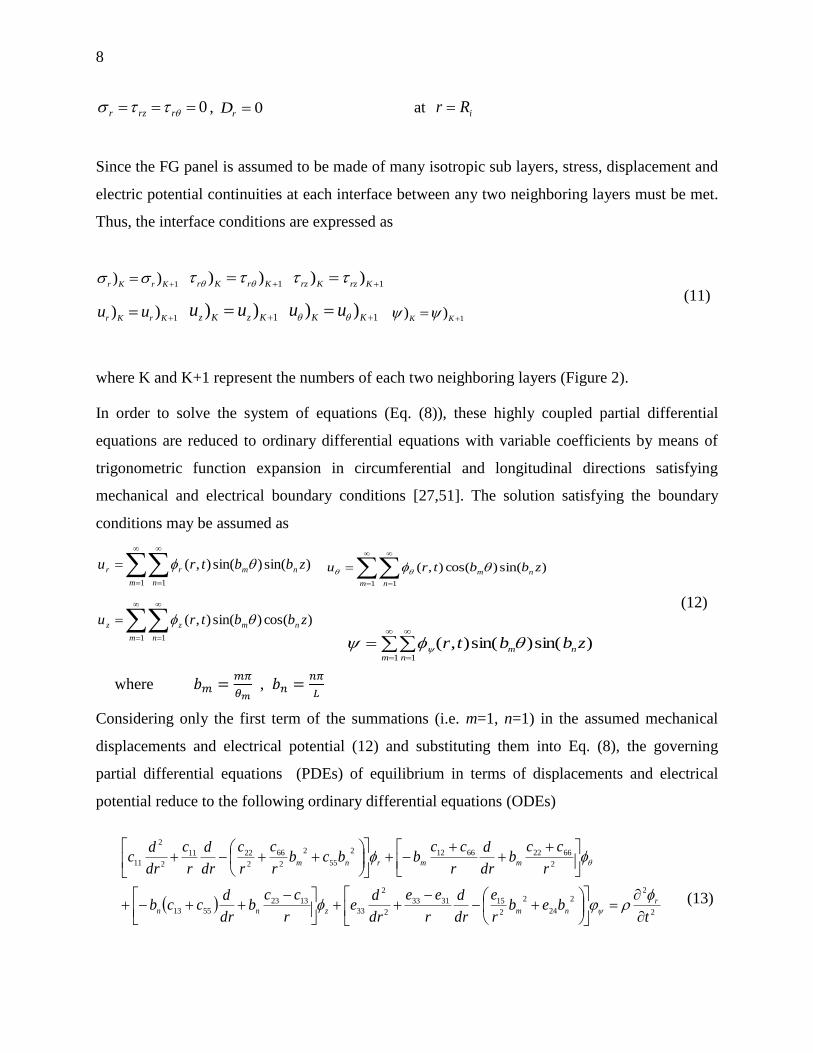
Since the FG panel is assumed to be made of many isotropic sub layers, stress, displacement and
electric potential continuities at each interface between any two neighboring layers must be met.
Thus, the interface conditions are expressed as
1))
KrKr
1))
KrKr 1
))
KrzKrz
(11)
1))
KrKruu
1))
KzKzuu
1))
KKuu
1
))
KK
where K and K+1 represent the numbers of each two neighboring layers (Figure 2).
In order to solve the system of equations (Eq. (8)), these highly coupled partial differential
equations are reduced to ordinary differential equations with variable coefficients by means of
trigonometric function expansion in circumferential and longitudinal directions satisfying
mechanical and electrical boundary conditions [27,51]. The solution satisfying the boundary
conditions may be assumed as
)sin()sin(),(
1 1
zbbtru nm
m n
rr
)sin()cos(),(
1 1
zbbtru nm
m n
)cos()sin(),(
1 1
zbbtru nm
m n
zz
)sin()sin(),(1 1
zbbtrnm
m n
(12)
where
,
Considering only the first term of the summations (i.e. m=1, n=1) in the assumed mechanical
displacements and electrical potential (12) and substituting them into Eq. (8), the governing
partial differential equations (PDEs) of equilibrium in terms of displacements and electrical
potential reduce to the following ordinary differential equations (ODEs)
2
22
24
2
2
153133
2
2
33
1323
5513
2
662266122
55
2
2
66
2
2211
2
2
11
tbeb
r
e
dr
d
r
ee
dr
de
r
ccb
dr
dccb
r
ccb
dr
d
r
ccbbcb
r
c
r
c
dr
d
r
c
dr
dc
r
nmznn
mmrnm
(13)

9
2
2
2
1531154423
2
44
2
2
22
2
6666
2
2
662
66221266
tb
r
e
dr
db
r
eebb
r
cc
bcbr
c
r
c
dr
d
r
c
dr
dcb
r
cc
dr
d
r
ccb
mmzmn
nmrmm
2
2
24
3224
2
33
2
2
4455
2
2
55
23445523
1355
tb
r
e
dr
dbee
bcbr
c
dr
d
r
c
dr
dcbb
r
ccb
r
cc
dr
dbcc
z
nn
znmmnrnn
02
22
2
2
1133
2
2
3332
2432
2
1515312
24
2
2
153331
2
2
33
nmznn
mmrnm
bbrdr
d
rdr
db
r
e
dr
dbee
br
e
dr
db
r
eebeb
r
e
dr
d
r
ee
dr
de
(2-22)
This system of equations are solved by considering linear shape functions and for
and as follows
sj
si
jis NN
s= r, , z ,
j
i
jiNN
(14)
where
ij
i
j
ij
j
irr
rrN
rr
rrN
,
Applying the formal Galerkin finite element method to the first equation of Eq. (13) yields
02
24
2
2
153133
2
2
33
1323
5513
2
662266122
55
2
2
66
2
2211
2
2
11
drN
bebr
e
dr
d
r
ee
dr
de
r
ccb
dr
dccb
r
ccb
dr
d
r
ccbbcb
r
c
r
c
dr
d
r
c
dr
dc
i
r
r
nmznn
mmrnmj
i
(15)
By integrating the other three ordinary differential equations, three similar equations are
obtained. Changing to and then repeating the above procedure, four other equations are
obtained. The result is written in the following finite element equilibrium equation for each non-
boundary element:
eeeee FXKXM
(16)

10
where [ ] , [ ] and { } are the mass, stiffness and force matrices, respectively and
jzjjrjiziiri
T
eX (17)
Applying the boundary conditions (9) and (10) for the first and last nodes in the inner and
outer surfaces and using Eq. (16), the finite element equilibrium equations for the first and last
elements become
11111 FXKXM ,
MIMIMIMIMI FXKXM (18)
Deriving the equilibrium conditions (11) in terms of displacement and electrical potential by
using Eqs. (1)-(5), the displacement components on the inner boundaries are obtained in terms of
values at neighboring nodes. Substituting results into Eq. (16), the finite element equilibrium
equations for two neighboring elements at interior (K)th and (K+1)th interfaces are obtained as
0KKKK
XKXM , 01111
KKKKXKXM (19)
Assembling Eqs. (16), (18) and (19), the general finite element equilibrium equation is obtained
as
FXKXM (20)
After establishing the finite element dynamic equation, the Newmark method is used to progress
in time domain as follows
1
2
1 )2/1( nnnnn XXtXtXX
11 )1( nnnn XXtXX (21)
where and are chosen to be 0.25 and 0.5, respectively to ensure the numerical stability
[27,51].
3. Numerical results and discussion
The piezoelectric laminate is an orthotropic material which properties are given as [52]

11
1010
56.200000
056.20000
0006.3000
0009.1343.778.7
00043.79.1343.7
00078.743.75.11
C
Pa
07.120000
7.1200000
00020.520.51.15
e
2. mC
910
46.600
046.60
0062.5
1. mF
(22)
The FG shell panel material is graded through the r-direction. It is made of a combined ceramic-
metal material which mixing ratio varies continuously and smoothly in the r-direction. The inner
surface of the shell panel (radius of a) is pure metal and the outer surface (radius of b) is pure
ceramic. The material distribution is shown by
m
n
mc Pab
arPPP
)()( (23)
where P stands for material property, n is a non-negative volume fraction exponent and
subscripts c and m stand for ceramic and metal, respectively. In the present study, the inner
surface of the shell is pure aluminum (Al) and the outer surface is pure alumina (Al2O3) which
properties are given in Table 1.
The FG shell panel is divided to M sub-shell panels (M layers) and each sub-shell panel is
assumed to be isotropic so that FG properties are obtained by a suitable arrangement of layers in
a multilayer panel. For example, the variation of density along the radial direction for three
different exponents n, using Eq. (23), is shown in Figure 3.
It is found that a proper number of sub-layers is M=50 for which a good agreement between
the present results and those from previous works is found. For M>50, the results have a
negligible change in comparison with the results for M =50.
12
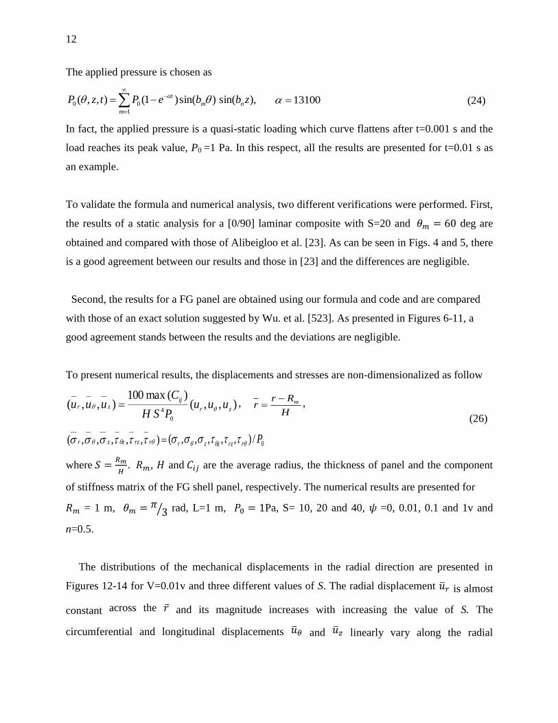
The applied pressure is chosen as
),sin()sin()1(),,(1
00 zbbePtzP nm
t
m
13100 (24)
In fact, the applied pressure is a quasi-static loading which curve flattens after t=0.001 s and the
load reaches its peak value, P0 =1 Pa. In this respect, all the results are presented for t=0.01 s as
an example.
To validate the formula and numerical analysis, two different verifications were performed. First,
the results of a static analysis for a [0/90] laminar composite with S=20 and 𝜃 deg are
obtained and compared with those of Alibeigloo et al. [23]. As can be seen in Figs. 4 and 5, there
is a good agreement between our results and those in [23] and the differences are negligible.
Second, the results for a FG panel are obtained using our formula and code and are compared
with those of an exact solution suggested by Wu. et al. [523]. As presented in Figures 6-11, a
good agreement stands between the results and the deviations are negligible.
To present numerical results, the displacements and stresses are non-dimensionalized as follow
),,()(max100
),,(0
4 zr
ijzr uuu
PSH
Cuuu ,
H
Rrr m ,
),,,,,( rrzzzr = 0/),,,,,( Prrzzzr
(26)
where
, and are the average radius, the thickness of panel and the component
of stiffness matrix of the FG shell panel, respectively. The numerical results are presented for
= 1 m, 𝜃 ⁄ rad, L=1 m, Pa, S= 10, 20 and 40, 𝜓 =0, 0.01, 0.1 and 1v and
n=0.5.
The distributions of the mechanical displacements in the radial direction are presented in
Figures 12-14 for V=0.01v and three different values of S. The radial displacement is almost
constant across the and its magnitude increases with increasing the value of S. The
circumferential and longitudinal displacements and linearly vary along the radial

13
direction . The smaller S (i.e. thicker panel), the larger slope of the variation of and . As
can be seen, this slope is almost the same for the piezoelectric and FG layers. Figure 15
illustrates the distribution of electrical potential across . The voltage is applied on the outer
piezoelectric layer and it acts as an actuator. The electrical potential 𝜓 linearly decreases from
the voltage V=0.01v applied on the outer surface to zero at the boundary of the piezoelectric and
FG layers. The same variation of 𝜓 occurs for each value of S, i.e., it is independent of the
piezoelectric thickness. For the inner piezoelectric layer, there is no applied voltage and it acts
as a sensor. The electrical potential is obtained to be zero at the inner surface and at the boundary
of the piezoelectric and FG layers. Therefore, the electrical boundary conditions and continuity
are satisfied. The electrical potential varies inside the sensor in the form of a parabolic-like
function across . Unlike in the actuator, the electrical potential depends on S and its magnitude
increases for smaller values of S (thicker piezoelectric layer). Note that the magnitude of the
obtained electrical potential in the sensor is much lower (two orders of magnitude) than the
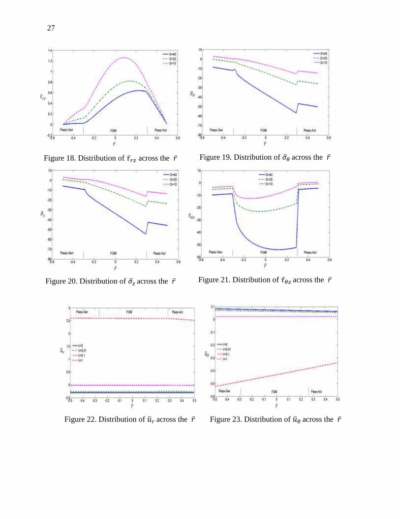
voltage applied on the actuator. The distributions of stress components 𝜎 , and across
are presented in Figures 16-18. The stress 𝜎 at the outer surface equals the applied pressure
(𝜎 ) and is zero on the inner surface which satisfies the mechanical boundary conditions.
Also, and are obtained to be zero on both the inner and outer surfaces of the piezoelectric
layers, in accordance with boundary conditions. All the stress components 𝜎 , and
linearly vary inside the atuator while they nonlinearly vary insde the sensor and the FG panel.
One more point is that these stresses are continuous across . Thus, the continuity conditions are
satisfied.
The distribution of stress components 𝜎 , 𝜎 and across are presented in Figures 19-21.
These stresses linearly vary across inside both the actuator and sensor layers. 𝜎 and 𝜎 also
linearly vary inside the FG panel. But, has a nonlinear variation in the FG panel. One more
point is that these stresses are not continuous across and there are jumps in the stresses at the
boundaries of the piezoelectric layers (specially the actuator) and the FG layer. This is because
no continuity condition was defined for these stresses.
The effect of applied voltage on displacements and stresses are shown in Figures 22-31 for
different voltages V=0, 0.01, 0.1 and 1v. As can be seen in Figure 22, for any applied voltage,

14
is almost constant across in the FG and piezoelectric layers. With increasing the voltage, the
compressive (-0.3) becomes tensile and its magnitude increases (up to 2.6 for V=1v). It is
found that increases linearly in terms of the applied voltage. As shown in Figures 23 and 24,
both and linearly vary across for any voltage and with increasing the voltage, the slopes
of their variations are larger and they change from compressive to tensile displacements.
The distribution of electrical potential for different applied voltages is presented in Figure 25.
For any voltage, the electrical potential linearly varies from the value of voltage applied on the
outer surface to zero value at the boundary between piezoelectric (actuator) and FG layers. But,
in the inner piezoelectric (sensor) layer, the electrical potential has a parabolic-like distribution
with zero value at its both sides. With increasing the voltage, the sensor response changes from
negative values to positive ones.
Figures 26-28 illustrate the distribution of 𝜎 , and across . All of these stress
components linearly increase across the actuator from the outer surface to the boundary between
the piezoelectric and FG layers after which they nonlinearly decrease to the inner surface.
However, the variation in the inner piezoelectric (sensor) layer is quite linear. The distributions
of 𝜎 , 𝜎 and across for different applied voltages are depicted in Figures 29-31. All of
these stress components vary inside the FG and piezoelectric layers quite linearly except
which varies in the FG layer nonlinearly. The larger the voltage, the larger the stresses are in the
FG and piezoelectric layers. However, does not follow the same manner.
Conclusions
A coupled three-dimensional elasticity and piezoeletricity solution for a functionally graded
shell panel with two piezoelectric layers is presented. The panel is simply supported at
circumferential edges and has a finite length. The governing equations are solved using the
Galerkin FEM and Newmark method. The present study has shown that the Fourier series
expansion in circumferential and longitudinal directions satisfying mechanical and electrical
boundary conditions is suitable for the mechanical displacement and electric potential analysis.
The effect of the piezoelectric layer subjected to outer pressure and applied voltages as an
actuator and the effect of the internal piezoelectric layer as a sensor are investigated. The results

15
of stress, displacement and electrical potential are presented for different FG panel thicknesses
and applied voltages and the following conclusions can be made
The mechanical and electrical boundary conditions and continuity conditions are
satisfied.
For the constant applied voltage (V=0.01v), with increasing S, is almost constant
across and its magnitude increases with increasing the value of S. and linearly
vary across . The smaller S (i.e. thicker panel), the larger slope of the variation of
and .
The electrical potential 𝜓 linearly decreases from the voltage applied on the outer
surface to zero at the boundary of the piezoelectric (actuator) and FG layers and it is
independent of the piezoelectric thickness. Inside the sensor layer, the electrical
potential varies in the form of a parabolic-like function across and it is zero at its
both sides. Unlike in the actuator, the electrical potential depends on S and its
magnitude increases for smaller values of S (thicker piezoelectric layer).
All the stress components 𝜎 , and linearly vary inside the atuator while they
nonlinearly vary insde the sensor and the FG panel. These stresses are continuous
across .
The stress components 𝜎 , 𝜎 and linearly vary across inside both the actuator
and sensor layers. 𝜎 and 𝜎 also linearly vary inside the FG panel. But, has a
nonlinear variation in the FG panel. Due to the lack of continuity conditions, these
stresses are not continuous across and there are jumps in the stresses at the
boundaries of the piezoelectric layers (specially the actuator) and the FG layer.
For any applied voltage, is almost constant across in the FG and piezoelectric
layers. With increasing the voltage, compressive becomes tensile and its
magnitude increases. It is found that increases linearly in terms of the applied
voltage. Both and linearly vary across for any voltage and with increasing
the voltage, the slopes of their variations are larger and they change from
compressive to tensile displacements.

16
For any voltage, electrical potential linearly varies from the value of voltage applied
on the outer surface to zero value at the boundary between piezoelectric (actuator)
and FG layers. But, in the inner piezoelectric (sensor) layer, the electrical potential
has a parabolic-like distribution with zero value at its both sides. With increasing the
voltage, the sensor response changes from negative values to positive ones.
The stress components 𝜎 , and linearly increase across the actuator from the
outer surface to the boundary between the piezoelectric and FG layers after which
they nonlinearly decrease to the inner surface. However, the variation in the inner
piezoelectric (sensor) layer is quite linear.
The stress components 𝜎 , 𝜎 and vary inside the FG and piezoelectric layers
quite linearly except which varies in the FG layer nonlinearly. The larger the
voltage, the larger the stresses are in the FG and piezoelectric layers. However,
does not follow the same manner.
The present work provides an enhanced insight to the mechanical and electric behaviors of
FG structures integrated with piezoelectric layers based on an effective layerwise FEM.
Acknowledgment
The support of Isfahan University of Technology is gratefully acknowledged.
References
1. Zhang, S.J., Li, F., Yu, F.P. ―Piezoelectric materials for cryogenic and high-temperature
applications, in F.-G. Yuan (Eds)‖, Struc. Health Monitor. (SHM) in Aerospace Struct.,
Woodhead Publishing, pp. 59-93 (2016)
2. Chalioris, C. E., Karayannis, C. G., Angeli, G. M., Papadopoulos, N. A., Favvata, M. J.,
Providakis, C.P. ‖Applications of smart piezoelectric materials in a wireless admittance
monitoring system (WiAMS) to Structures—Tests in RC elements‖, Case Studies in Const.
Mater., 5, pp. 1-18 (2016)

17
3. Ribeiro, C., Sencadas, V., Correia, D.M., Lanceros-Méndez, S. ―Piezoelectric polymers as
biomaterials for tissue engineering applications‖, Coll. Surf. B: Biointerfaces, 136, pp. 46-55
(2015)
4. Ho, Sh.-T., Jan, Sh.-J. ―A piezoelectric motor for precision positioning applications‖,
Precision Eng, 43, pp. 285-293 (2016)
5. Ma, H.-K., Luo, W.-F., Lin, J.-Y. ―Development of a piezoelectric micropump with novel
separable design for medical applications‖, Sens. and Actu. A: Physical, 236, pp. 57-66 (2015)
6. Abella, F., Ribot, J., Doria, G., Duran-Sindreu, F., Roig, M. ―Applications of piezoelectric
surgery in endodontic surgery: A Literature Review‖, J. of Endodontics, 40, pp. 325-332 (2014)
7. Camarda, A., Romani, A., Tartagni, M. ―Piezoelectric transformers for ultra-low voltage
energy harvesting applications‖, Procedia Eng., 87, pp. 1521-1524 (2014)
8. Zhang, J., Meguid, S. A. ―On the piezoelectric potential of gallium nitride nanotubes‖, Nano
Energy, 12, pp. 322-330 (2015)
9. Momeni, K. ―A multiscale approach to nanocomposite electrical generators‖, Nano Energy, 4,
pp. 132-139 (2014)
10. Pan, X. H., Yu, S. W., Feng, X. Q. ―A continuum theory of surface piezoelectricity for
nanodielectrics‖, Sci. China Phys. Mech. Astron., 54, pp. 564-573 (2011)
11. Dai, S., Gharbi, M., Sharma, P., Park, H. S. ―Surface piezoelectricity: size effects in
nanostructures and the emergence of piezoelectricity in non-piezoelectric materials‖ J. Appl.
Phys., 110, 104305 (2011)
12. Momeni, K., Odegard, G. M., Yassar, R. S. ―Nanocomposite electrical generator based on
piezoelectric zinc oxide nanowires‖, J. Appl. Phys., 110, 114303 (2010)
13. Momeni, K., Mortazavi, S. M. Z. ―Optimal aspect ratio of zinc oxide nanowires for a
nanocomposite electrical generator‖, J. Comput. Theor. Nanosci., 9 (10), pp. 1670-1674 (2012)
14. Koizumi, M., ―The concept of FGM ceramic transactions‖, Func. Grad. Mater., 34, pp. 3-10
(1993)
15. Moya, J.S., ―Layered ceramics‖, Adv. Mater., 7, pp. 185-189 (1995)
16. Lu, P., Lee, H.P., Lu, C. ―Exact solutions for simply supported functionally graded
piezoelectric laminates by Stroh-like formalism‖, J. of Compos. Struct., 72, pp. 352-363 (2006)
17. Askari Farsangi, M. A. ―An analytical solution for dynamic behavior of thick doubly curved
functionally graded smart panels‖, J. of Compos. Struct., 107, pp. 88-102 (2014)

18
18. Jafari Fesharaki, J. , Jafari Fesharaki, V. , Yazdipoor, M. , Razavian, B. ―Two-dimensional
solution for electro-mechanical behavior of functionally graded piezoelectric hollow cylinder‖,
Appl. Mathematical Model., 36(11), pp. 5521-5533 (2012)
19. Bodaghi, M., Shakeri, M. ―An analytical approach for free vibration and transient response
of functionally graded piezoelectric cylindrical panels subjected to impulsive loads‖, Compos.
Struct., 94(5), pp. 1721-1735 (2012)
20. Duc, N.D. , Quan, T. Q. , Luat, V. D. ―Nonlinear dynamic analysis and vibration of shear
deformable piezoelectric FGM double curved shallow shells under damping-thermo-electro-
mechanical loads‖, Compos. Struct., 125, pp. 29-40 (2015)
21. PCY, L., JD, Y. ―Governing equations of piezoelectric plates with graded properties across
the thickness‖, Pro Annu. IEEE. Int. Freq. Cont. Symp, pp. 623-631 (1996)
22. Behjat, B., Sadighi, M., Armin, A., Abbasi, M., Salehi, M. ‖Static,Dynamic and free
vibration analysis of functionally graded piezoelectric panels using finite element method‖, J.
Intell. Mater. Sys. Struct., 20(13), pp. 1635–1646 (2009)
23. Alibeigloo, A., Chen, W. Q. ―Elasticity solution for an FGM cylindrical panel integrated
with piezoelectric layers‖, Europ. J. of Mech. - A/Solids, 29(4), pp. 714-723 (2010)
24. Behjat, B. , Salehi, M. , Armin, A. , Sadighi, M. , Abbasi, M. ―Static and dynamic analysis of
functionally graded piezoelectric plates under mechanical and electrical loading‖, Scientia
Iranica, 18(4), pp. 986-994 (2011)
25. Panda, S., Ray, M.C. ―Nonlinear finite element analysis of functionally graded plates
integrated with patches of piezoelectric fiber reinforced composite‖, Finite Elem. in Anal. and
Des., 44, pp. 493-504 (2008)
26. Javanbakht, M., Daneshmehr, A. R., Shakeri, M., Nateghi, A. R. ―The dynamic analysis of
the functionally graded piezoelectric (FGPM) shell panel based on three-dimensional elasticity
theory‖, Appl. Math. Model., 36, pp. 5320-5333 (2012)
27. Javanbakht, M., Shakeri, M., Sadeghi, S.N. ―Dynamic analysis of functionally graded shell
with piezoelectric layers based on elasticity‖, Proc. Inst. Mech. Eng. C J. Mech. Eng. Sci., 223,
pp. 2039-2047 (2009)
28. Javanbakht, M., Shakeri, M., Sadeghi, S.N., Daneshmehr, A.R. ―The analysis of functionally
graded shallow and non-shallow shell panels with piezoelectric layers under dynamic load and
electrostatic excitation based on elasticity‖, Europ. J. of Mech. - A/Solids, 30, pp. 983-991 (2011)
19
29. Bhangale, R.K., Ganesan, N. ―Static analysis of simply supported functionally graded and
layered magneto-electro-elastic plates‖, Int. J. of Sol. and Struct., 43, pp. 3230-3253 (2009)
30. Shakeri, M., Akhlaghi, M., Hoseini, S.M. ―Vibration and radial wave propagation velocity in
functionally graded thick hollow cylinder‖, J. of Compos. Struc., 76, pp. 174-181 (2006)
31. Huang, X. L., Shen, H.-S. ―Vibration and dynamic response of functionally graded plates
with piezoelectric actuators in thermal environments‖, J. of Sou. and Vib., 289, pp. 25-53 (2006)
32. Rouzegar, J., Abad, F. ―Free vibration analysis of FG plate with piezoelectric layers using
four-variable refined plate theory‖, Thin Wall. Struct., 89, pp. 76-83 (2015)
33. Shakeri, M., Sadeghi, S.N., Javanbakht, M., Hatamikian, H. ―Dynamic analysis of
functionally graded plate integrated with two piezoelectric layers, based on three dimensional
elasticity solution‖, Proc. Inst. Mech. Eng. C J. Mech. Eng. Sci., 223, pp. 1297-1309 (2009)
34. Yiqi, M., Yiming, F. ―Nonlinear dynamic response and active vibration control for
piezoelectric functionally graded plate‖, J. of Sou. and Vib., 329(11), pp. 2015-2028 (2010)
35. Akbari Alashti, R. , Khorsand, M. ―Three-dimensional thermo-elastic analysis of a
functionally graded cylindrical shell with piezoelectric layers by differential quadrature method‖,
Int. J. of Press. Vess. and Pipe., 88(5-7), pp. 167-180 (2011)
36. Kiani, Y., Sadighi, M., Eslami, M.R. ―Dynamic analysis and active control of smart doubly
curved FGM panels‖, Compos. Struct.,102, pp. 205-216 (2013)
37. He, X. Q., Ng, T. Y., Sivashankar, S., Liew, K. M. ―Active control of FGM plates with
integrated piezoelectric sensors and actuators‖, Int. J. of Sol. and Struct., 38, pp. 1641-1655
(2001)
38. Kong, Y., Liu, J. ―Vibration confinement of thickness-shear and thickness-twist modes in a
functionally graded piezoelectric plate‖, Acta Mech. Soli. Sin., 24(4), pp. 299-307 (2011)
39. Dehghan, M., Zamani Nejad, M., Moosaie, A. ―Thermo-electro-elastic analysis of
functionally graded piezoelectric shells of revolution: Governing equations and solutions for
some simple cases‖, Int. J. of Eng. Sci., 104, pp. 34-61 (2016)
40. Jafari, A.A. , Khalili, S.M.R. , Tavakolian, M. ―Nonlinear vibration of functionally graded
cylindrical shells embedded with a piezoelectric layer‖, Thin Wall. Struct., 79, pp. 8-15 (2014)
41. Liew, K. M., Yang, J., Kitipornchai, S. ―Postbuckling of piezoelectric FGM plates subject
tothermo-electro-mechanical loading‖, Int. J. of Sol. and Struct., 40, pp. 3869-3892 (2003)

20
42. Shen, H.-S. ―Postbuckling of axially loaded FGM hybrid cylindrical shells in thermal
environments‖, Compos. Sci. and Tech., 65(11-12), pp. 1675-1690 (2005)
43. Shen, H.-S., Noda, N. ―Postbuckling of pressure-loaded FGM hybrid cylindrical shells in
thermal environments‖, Compos. Struct., 77(4), pp. 546-560 (2007)
44. Shen, H.-S., Liew, K. ―Postbuckling of axially loaded functionally graded cylindrical panels
with piezoelectric actuators in thermal environments‖, J. of Eng. Mech., 130(8), pp. 982-995
(2004)
45. Shen, H.-S., Li, S. R. ―Postbuckling of sandwich plates with FGM face sheets and
temperature-dependent properties‖, Compos. Part B: Eng., 39, pp. 332-344 (2008)
46. Shen, H.-S. ―Nonlinear thermal bending response of FGM plates due to heat conduction‖,
Compos Part B: Eng., 38, pp. 201-215 (2007)
47. Sladek, J., Sladek, V., Stanak, P., Zhang, C., Wünsche, M. ―Analysis of the bending of
circular piezoelectric plates with functionally graded material properties by a MLPG method‖,
Eng. Struct., 47, pp. 81-89 (2013)
48. Wu, C.–P., Liu, Y.-C. ―A review of semi-analytical numerical methods for laminated
composite and multilayered functionally graded elastic/piezoelectric plates and shells‖, Compos.
Struct., 147, pp. 1-15 (2016)
49. Gupta, A., Talha, M. ―Recent development in modeling and analysis of functionally graded
materials and structures Progress in Aerospace Sciences‖, Prog. in Aerospace Sci., 79, pp. 1-14
(2015)
50. Thai, H.-T., Kim, S.-E. ―A review of theories for the modeling and analysis of functionally
graded plates and shells‖, Compos. Struct., 128, pp. 70-86 (2015)
51. Daneshmehr, A., Shakeri, M. ―The response analysis of the piezoelectric shell panel
actuators based on the theory of elasticity‖, ASME 7th Bien. Conf. on Eng. Syst. Des. and
Analysis, 2, Manchester, England, pp. 133-141 (2004).
52. Daneshmehr, A.R., Shakeri, M. ―Three-dimensional elasticity solution of cross-ply shallow
and non-shallow panels with piezoelectric sensors under dynamic load‖, Compos. Struct., 80, pp.
429-439 (2007)
53. Wu, X.-H., Shen, Y.-P., Chen, C. ―An Exact Solution for Functionally Graded
Piezothermoelastic Cylindrical Shell as Sensors or Actuators‖, Mater. Letters, 57, pp. 3532-3542
(2003)

21
Mahdi Javanbakht received his BS (2002-2004) and MS (2004-2006) degrees in Mechanical
Engineering from Amirkabir University of Technology (AUT), and his PhD in Mechanical
Engineering (2009-2013) from Iowa State University (ISU), USA. He was a postdoctoral
associate for one year at Aerospace Engineering Dept. at ISU. In 2014, he first joined AUT as a
faculty member and then moved to Isfahan University of Technology (IUT) in 2015. Currently,
he is an assistant professor at Mechanical Engineering Dept, IUT. His interests include solid
mechanics, nanomechanics and nanomaterials, and modeling of physical phenomena.
Mohammad Mohammadian received his BS degree in Mechanical Engineering in Thermo-
fluid engineering from University of Kashan, Kashan, Iran in 2013. He has recently graduated
with as MS degree from Isfahan University of Technology, Isfahan, Iran. His research interests
include FEM, theories of plates and shells, and composite materials.
List of figure and table captions
Figure 1. Geometry of the FG shell panel with piezoelectric layers
Figure 2. Configuration of the K and K + 1 layers.
Figure 3. Variation of density in layers in the radial direction.
Figure 4. Distribution of 𝜎 across the
Figure 5. Distribution of 𝜎 across the
Figure 6. Distribution of 𝜎 across the ( ⁄ 𝜃 𝜃 ⁄ )
Figure 7. Distribution of 𝜎 across the ( ⁄ 𝜃 𝜃 ⁄ )
Figure 8. Distribution of 𝜎 across the ( ⁄ 𝜃 𝜃 )
Figure 9. Distribution of across the ( ⁄ 𝜃 𝜃 )
Figure 10. Distribution of across the ( ⁄ 𝜃 𝜃 )
Figure 11. Distribution of across the ( ⁄ 𝜃 𝜃 )
Figure 12. Distribution of across the
Figure 13. Distribution of across the
22
Figure 14. Distribution of across the
Figure 15. Distribution of 𝜓 across the
Figure 16. Distribution of 𝜎 across the
Figure 17. Distribution of across the
Figure 18. Distribution of across the
Figure 19. Distribution of 𝜎 across the
Figure 20. Distribution of 𝜎 across the
Figure 21. Distribution of across the
Figure 22. Distribution of across the
Figure 23. Distribution of across the
Figure 24. Distribution of across the
Figure 25. Distribution of 𝜓 across the
Figure 26. Distribution of 𝜎 across the
Figure 27. Distribution of across the
Figure 28. Distribution of across the
Figure 29. Distribution of 𝜎 across the
Figure 30. Distribution of 𝜎 across the
Figure 31. Distribution of across the
Table 1. Material properties of Al and Al2O3

23
Figure 1. Geometry of the FG shell panel with piezoelectric layers
Figure 2. Configuration of the K and K + 1 layers.
Table 1. Material properties of Al and Al2O3
Al Al2O3
Young Modulus (GPa) 70 380
Mass Density (Kg/m3) 2702 3800
𝜃𝑚
𝜃

24
Figure 3. Variation of density in layers in the radial direction.
Figure 4. Distribution of 𝜎 across the
Figure 5. Distribution of 𝜎 across the

25
Figure 6. Distribution of �� across the
( ⁄ 𝜃 𝜃 ⁄ )
Figure 7. Distribution of �� across the
( ⁄ 𝜃 𝜃 ⁄ )
Figure 8. Distribution of �� across the
( ⁄ 𝜃 𝜃 )
Figure 9. Distribution of across the
( ⁄ 𝜃 𝜃 )
Figure 10. Distribution of across the
( ⁄ 𝜃 𝜃 )
Figure 11. Distribution of across the
( ⁄ 𝜃 𝜃 )

26
Figure 12. Distribution of across the
Figure 13. Distribution of across the
Figure 14. Distribution of across the
Figure 15. Distribution of 𝜓 across the
Figure 16. Distribution of 𝜎 across the
Figure 17. Distribution of across the
27
Figure 18. Distribution of across the
Figure 19. Distribution of 𝜎 across the
Figure 20. Distribution of 𝜎 across the
Figure 21. Distribution of across the
Figure 22. Distribution of across the
Figure 23. Distribution of across the

28
Figure 24. Distribution of across the
Figure 25. Distribution of 𝜓 across the
Figure 26. Distribution of 𝜎 across the
Figure 27. Distribution of across the
Figure 28. Distribution of across the
Figure 29. Distribution of 𝜎 across the

29
Figure 30. Distribution of 𝜎 across the
Figure 31. Distribution of across the