laycock type a overdrive units a different perspective 12
TRANSCRIPT

LAYCOCK TYPE A OVERDRIVE UNITS – A different perspective – 12 MODES.
Also: Calculating the O/D ratios and speedometer calibration issues in TR cars:
H. Holden 2010.
There has been much information published on the functionality of the Laycock type A units, however it
seemed to me that some of it has led to some myths relating to the function of the unit. For example on
one website dedicated to triumph matters the remark was made that the cone clutch return springs were
increased from 4 to 8 to allow for the extra torque of the higher performance motors when in fact the
return springs have no role in the transfer of power in the forward direction in overdrive mode or not (see
below).
Undoubtedly the Laycock O/D units were a futuristic design and still today are very impressive pieces of
mechanical and hydraulic engineering. The symmetry of the epicyclic gear system with the sun gear,
three planet gears and an annulus gear is very appealing.
Brief description of the unit:
The Laycock O/D has a number of working components including a pair of hydraulically operated pistons
which move after the driver selects O/D. These move a cone clutch attached on splines to a sun gear, to
stall them both onto a brake ring attached to the O/D body. This running surface on the cone clutch is
important in engaging the overdrive. The input power to the O/D unit is applied via the input shaft (the
gearbox’s output shaft) to a “planet carrier” containing 3 planet gears which interface both with the output
annulus (which is part of the output shaft) and with the sun gear. When the sun gear is stalled the planet
carrier rotates around the sun gear and the planet gear teeth drive the annulus at a higher rpm than the
input shaft, hence the term “overdrive”. The input shaft can also drive the annulus directly through a one
way meta-metal clutch known as a sprag clutch. Looking from the front of the car, clockwise rotation of
the input shaft at a higher rpm than the annulus causes the input shaft to couple to the annulus via the
sprag clutch and supply torque to the driveshaft. When O/D is selected the higher rotational rate of the
annulus with respect to the input shaft produces a relative anti-clockwise rotation of the input shaft with
respect to the annulus so the sprag clutch uncouples. When the cone clutch is not stalled on the brake
ring (as it is in O/D mode) it is returned by springs to a second operating clutch face on the annulus. This
running surface has important applications in coast and in reverse gear as will be explained.
There are three states of position of the cone clutch: either returned to the annulus, “free-wheeling” (if
only briefly or in a slip condition) or locked to the brake ring (3 modes). Then you could attempt to transfer
drive torque in the forward or reverse direction (fwd or reverse gearbox gears selected) into the O/D unit
(2 modes). Then there is the situation in "coast" where the car itself attempts to push the drive power
back through the unit’s output to force the engine RPM up. In this case say coasting down a hill where the
car acquires gravitational kinetic energy and transfers power through the O/D unit toward the engine and
there is a torque reversal and torque is transferred from the wheels to the engine. This adds another two
modes. So theoretically at least this results in 3 x 2 x 2 = 12 potential operating modes. Some of these 12
possible states are prohibited or not normally possible such as overdrive mode in reverse gear.
(When terms such as clockwise and anticlockwise are used in this article, this is viewed from the front of
the car).
If we look at the theoretical modes one by one to see how torque is transferred via the O/D unit a clear
picture is obtained about the function of the important parts. This is shown initially in figure 1 below:

:
1) Reverse gear in non overdrive mode - torque from engine to wheels:
In this case the sprag clutch is uncoupled due to relative anticlockwise rotation of the input shaft with
respect to the annulus. Power transmission is via the cone clutch system (and the return spring
force) which locks the sun gear, via the cone clutch, to the annulus and the planet carrier therefore is
locked. Torque and drive power is transferred via the input shaft to the annulus.
See No.5 below for the pathology when this clutch surface slips.
2) Forward gear non overdrive mode - torque from engine to wheels:
In this situation the torque and power are transferred by the metal-metal “Sprag Clutch” This is more than
a usual type of clutch and is exceptionally slip resistant. In the forward direction it jams itself closed in

proportion to the drive torque. The greater the torque the tighter this clutch binds. It has roller bearings
that are forced up an inclined plane by the drive, expanding the diameter of the assembly and jamming
the rollers into their housing in the annulus body.
Also in this instance the drive is also applied by the input shaft to the planet carrier. The sun gear is
locked by the cone clutch surface to the annulus and this clutch surface would also couple the drive in
the same way as it does in reverse (see No 1 above), however this clutch could slip especially in 4th gear
when the forces on the clutch surfaces were highest. If this clutch surface attempted to slip there is still
the power transmission by the sprag clutch, so no slip is noted by the driver in forward drive non O/D
mode, even with weak return springs and a worn cone clutch lining.
3) Reverse gear non overdrive mode in coast, torque from wheels to engine:
In this case the reverse rotation of the O/D output shaft attempts to exceed the angular velocity or rpm (in
reverse) of the O/D input shaft. The relative motion of the input shaft with respect to the annulus is
clockwise, therefore this engages the sprag clutch. No slip is likely.
4) Forward gear non overdrive mode in coast, torque from wheels to engine:
In this case the Sprag clutch is uncoupled because the angular velocity or RPM of the annulus exceeds
that of the input shaft, so the only way forces can be transmitted back to the G/box is via the cone clutch
and return spring system holding the cone clutch to the annulus. The cone clutch is coupled to the sun
gear and locked to the planet carrier so the torque is transmitted back to the input shaft.
See No 8 below for pathology with a slipping or free-wheeling clutch surface in this mode.
5) Free-wheeling cone clutch, in reverse gear, torque from engine to wheel:
If the cone clutch is worn or the return springs are weak (or often both) the cone clutch slips on the
annulus and the sun gear starts to rotate. As is does this no power can be transferred. The car owner
notices a “slip” in reverse and can't reverse the car up an incline. This is not an uncommon fault in the
heavier Saloon Triumphs which also had a cone clutch carrier with only 4 springs instead of 8 unlike
TR2-6.
6) Free wheeling cone clutch, in fwd gear, torque from engine to wheels:
Torque is still transmitted from the engine to the wheels via the sprag clutch. The freewheeling condition
occurs briefly in the normal selection of O/D. In this case the drive is still continuously transmitted via the

one way sprag clutch, so that the engine RPM doesn't shoot up due to loss of coupling during the
transition into O/D mode, a very clever design feature.
(When the O/D is selected, and the sun gear is stalled to the O/D body, the OD's output RPM attempts to
increase, but due to the mass of the vehicle, compared to the mass of the moving parts in the engine and
drive train the driver notices a sudden drop in RPM instead and little change in road speed. This is an
example of the physical science principle of the conservation of momentum).
7) Free-wheeling cone clutch, reverse gear - torque from wheel to engine:
This situation was described in No.3 above in that any cone clutch slip here bypassed by the sprag
clutch therefore no slip is detected.
8) Free wheeling cone clutch in forward gear - torque from wheel to engine:
With a free-wheeling/slipping cone clutch the O/D would fail to engage as there would be insufficient
friction between it and the brake ring. You wouldn't know anything was wrong until the overdrive was
selected. With regards to the clutch surface between the cone clutch and annulus, then in coast there will
be no engine braking. In one of the Laycock manuals they mention a consequence of weak springs as
“slip on over-run” or coast. With free-wheeling or absent friction on the brake ring side of the clutch
surface, the O/D would fail to engage.
9) Reverse gear drive in overdrive mode - torque from engine to wheels:
This is prohibited because it results in a problem. The sprag clutch is initially uncoupled because the
relative motion of the input shaft to the annulus is anticlockwise. Due to the overdrive attempting to make
the output annulus run at a higher angular velocity counter clockwise than the input shaft RPM the result
is relative clockwise rotation of the input shaft with respect to the annulus. This as usual results in the
sprag clutch engaging. So in effect you have the overdrive epicyclic gearing system fighting the sprag
clutch which as mentioned is a phenomenally effective clutch. This can result in mechanical destruction of
the planet/sun annulus gears and the sprag clutch it has been said.
This catastrophe suggested above still relies on the stalling of the cone clutch surface to the brake ring
and with that the stalling of the sun gear to engage the O/D. One would hope this clutch surface might slip
and provide some protection. The hydraulic forces, via the pistons holding the cone clutch to the brake
ring, build up with speed of the input shaft, so if reversing slowly the O/D probably would not engage even
if it was selected. So you pray that your gearbox inhibitor switched never shorts out in the middle of a
rapid car reversal down a long driveway and you have also forgotten to switch off the OD. The scenario is
unlikely unless the gearbox switch/s or wiring to those short out to the car body. An OLU (overdrive logic
unit) can help here as the overdrive cannot remain engaged without repeat selection by the driver, who
probably wouldn’t do that in reverse. However as mentioned in my article on OLU’s on this website you
need to be sure that a fault mode in the OLU is not capable of selecting the O/D in reverse mode.
10) Forward gear in overdrive mode - torque from engine to wheels:
In this case the sun wheel is stalled to the O/D body by the cone clutch assembly. The forces holding it
there are derived from the hydraulics and the operating pistons and are in fact reduced by the
return spring forces opposing them, but there is about a 5:1 force ratio in Hydraulic force to Spring force
and the hydraulic forces dominates. In this mode drive power is transmitted via the planet carrier and
planet gears to the annulus and for a single rotation of the planet carrier there is a greater rotation of the
annulus, hence the “overdrive”. In this situation the sprag clutch in uncoupled because the output angular
velocity or RPM of the annulus forming the outer part of this clutch is exceeding the input shaft RPM
resulting in relative counter clockwise rotation of the input shaft with respect the annulus.
It is worth noting again that when the O/D is selected, that the car, due to its momentum, stabilizes its
own road speed, hence the O/D’s output flange RPM is stabilized because the car’s momentum is
significantly greater than that of the rotating engine and gearbox components so the driver experiences a
drop in engine rpm and little change in road speed. If an O/D unit is tested in a car with the driveshaft
removed and the O/D selected, the engine RPM stays nearly constant and the output flange alone (with
low momentum) increases its velocity and the indicated speed on the speedometer jumps up quickly.
11) Reverse gear and overdrive mode in coast - torque via wheels to engine:
Not generally applicable as a scenario as the unit could not have been in the O/D mode in reverse and if
it was would have already failed (R.I.P).
12) Forward gear and overdrive mode in coast - torque via wheels to engine:
In this instance the unit was in overdrive and the wheels attempt to drive the engine at a higher RPM
than it is running, engine braking if you like. Again the sprag clutch is in the uncoupled direction. Power is
transferred via the annulus and planet gears around the stationary sun gear the OD acts like a fixed ratio
G/box with the output rpm (of the OD unit) higher than its input RPM at all times.
OVERDRIVE HYDRAULICS:
There are a number of descriptions of this in the manuals. Again a slightly different approach is used to
describe it here. The basic arrangement is a pump that raises the fluid pressure (from the zero reference
level which is atmospheric pressure) to around 400psi. The pump is driven from a cam on the input shaft
and has a non return valve on its output and produces pulses of fluid which charge (fill) a compliant
chamber (accumulator) with oil. This chamber consists of a space enclosed by a piston top and bore, and
the compliance or elasticity of the chamber is derived from a piston return spring. With increasing
pressure the volume of the chamber expands by piston displacement and elongation of the bore. This
compliance or “fluidic capacitance” helps to smooth out the pulsations from the pump. The non return
valve prevents fluid in the accumulator bleeding back into the pump.

The accumulator chamber serves a dual purpose because at a certain level of pressure and piston
displacement, holes are then exposed in the side of the bore to bleed away oil. The net result is that the
accumulator piston/bore assembly also behaves as a pressure regulator, significantly stabilizing the
pressure to around 400psi to 450psi regardless of increased pump output with input shaft rpm increasing.
One way to describe this function is a “comparator” where the pressure and therefore the force on the
piston head in the accumulator chamber is compared to a fixed reference value (the spring force) and
produces an error output. The error output, so to speak, of this comparator is a mechanical action to
expose bypass holes and this controls a flow resistance (the holes) to bypass fluid out of the accumulator
chamber and back to the overdrive sump. The sump has a pressure we could call the zero reference
level.
A compliant chamber or accumulator simply has the property of increasing its volume with increasing
applied pressure, in the same way an electrical capacitor for example has the property of holding an
increasing electrical charge with increasing applied electrical pressure or voltage.
An operating valve connects the accumulator chamber to two operating pistons. This couples the
accumulator pressure into the chambers enclosed by the operating piston faces. The pressure causes
displacement of the pistons, so this space is transiently significantly compliant and there is a momentary
sag in hydraulic pressure until the operating pistons stop moving. The pistons stop moving after a specific
displacement because they push on to two metal bars attached to the cone clutch carrier and push the
cone clutch onto the brake ring thereby initiating overdrive. To do this they overcome the force of the 8
return springs. If one multiplies the 400 psi by the both the piston surface areas, about 3 square inches,
and converts the pound value, about 1200 pounds, to Newtons, the force is around 5000 Newtons.
Approximately 1000N of this is used in overcoming the 8 cone clutch return springs so around 4000N is
available to act on the cone clutch and brake ring surface. In the Triumph saloon cars they ran a lower
hydraulic pressure around 300 to 320 psi (had a weaker accumulator spring) and they also often had only
4 cone clutch return springs. This gave a softer O/D engagement, and with a worn cone clutch, slip was
more likely in reverse gear.
Some O/D units had different sized accumulator pistons and dual rather than single return springs.
The operating valve is deployed by an operating arm which crosses the body of the O/D unit and sealed
to the body with two small O rings. (When O/D units are rebuilt it is worth replacing these to prevent oil
seepage to the outside of the unit). This operating arm is actuated by a dual coil solenoid which has a pull
in and a holding coil with a lower current consumption than the pull in coil. This assembly needs correct
adjustment or the internal switch in this coil does not disconnect the pull in coil and this can cause the
solenoid to burn out due to the large average power consumption of this coil.
Before presenting the next “system diagram” of the O/D hydraulics, which the reader won’t have seen
before, it is worth noting that there are similarities between electrical and hydraulic systems such that:
Pressure is analogous to voltage:
Pressure is generally measured in force per unit area, eg Newtons per square meter, however its effects
are much better understood by multiplying the force and area by a linear dimension (meters) then the
units of pressure become Newton.meters per cubic meter which is Joules per cubic meter.
Therefore pressure can be thought of as an “energy density”. This energy is capable of doing work on a
mass of fluid, transporting it around a fluid flow pathway. Pressure drives fluid around hydraulic circuits
and voltage drives current around electrical circuits. Voltage has energy density units too, of Joules per
Coulomb of charge. A Coulomb is a large amount or volume of electrons.
Accumulators are analogous to capacitors:
Accumulators have an increased stored volume of fluid with increasing hydraulic pressure and a capacitor
has an increased stored amount of electrical charge with an increase in electrical pressure or increasing
voltage.
Flow resistance in hydraulic pathways is analogous to electrical resistance:
The flow of fluid via tubing, or constrictions, results in interaction of the fluid molecules to generate heat
and waste energy. This dissipates pressure energy along the way and the pressure drops. Flow of
electrical current also generates heat and dissipates voltage due to electrical flow resistance in the
conductors. In each case the pressure energy density and voltage energy density is lost irreversibly as
heat with frictional processes. In most electrical resistors the resistance value itself is independent of the
flow rate or electrical current. This is sometimes the case in hydraulic systems where the flow rate or fluid
current is perfectly laminar. However in many hydraulic flow situations the flow is turbulent and the flow
resistances increase with flow rate. This always occurs where flow is directed into constricted passages.
Fluidic inertia is equivalent to electrical inductance:
A mass of fluid, say in tubing has inertia, or the reluctance to start moving or be accelerated when acted
on by a force or pressure. There is a reactive or opposing force generated by the mass (for each action
there is an equal and opposite reaction).The mass resists having its motion changed. A flow of fluid or
fluid current in a tube resists changing its existing velocity or flow rate when an abrupt pressure change is
applied. In electrical circuits this inertia is represented by electrical Inductance in that an inductor resists a
change in current by producing a reactive force or reactive voltage, opposing a change in current.
In light of the above similarities between electrical and hydraulic systems then any hydraulic flow circuit
can be represented by its electrical flow circuit equivalent. Why would one want to do that? It helps a little
because resistors can be added where leakage pathways can occur and the effect of this is readily
visible. Also it helps simplify certain calculations. In addition known electrical circuit laws such as Ohms
law, Kirchoff’s law and the Thevenin theorem and the formulae for adding resistors or capacitors in
parallel or series can then be applied.
In many hydraulic models, such as the one for the Laycock O/D unit I made below the fluidic inertia
(inductance equivalent of the fluid in the fluid pathway) is not required to represent the function of the unit,
so only voltage, resistance and capacitance equivalents are needed and no inductance symbols are
required. A one way hydraulic flow valve has the electrical equivalent is the diode. An on/off valve like the
operating valve is represented as a switch and the comparator function of the accumulator wall holes and
piston and spring assembly is represented by the triangular shape as an electrical comparator would be:


Some of the early O/D units had very effective operating piston seals which were metal. These could
score the aluminium bore, however the hydraulic seal was excellent increasing the leakage flow
resistance RLpis which is the parallel combination of the leakage resistances around the two operating
pistons. Later these were replaced by rubber O rings.
O/D RATIOS AND SPEEDOMETER DRIVES:
As time has passed various O/D units such as those from Triumph saloon cars have been used as donor
parts or replacements units or upgrades to TR cars. Some units have come as donor parts units from
Austin Healey’s and Jaguars. This can induce some interesting issues with speedometer calibration.
The following diagram below shows information on how to calculate the O/D ratios based on the number
of gear teeth, and information about speedometer drive ratios that I have worked out. The planet gears
are double gears and that is also taken into account. It would appear that the original diagram of this unit
shown below was published or belongs to British Leyland, so they deserve the credit for what I can only
describe as a masterful piece of technical drawing. Some colours have been added to highlight certain
parts and the labels with the equations to calculate the O/D ratio.

The O/D’s with a 28 part number have the greatest O/D ratio. These were typically used in Jaguars and
the 22 suffix part numbers use in TR cars. There is also apparently a 25% unit I have not seen.
Taking the 28% example if the RPM was 3000 prior to O/D engagement then the engine RPM would drop
to 3000/1.28 or to 2344RPM after the O/D was engaged at the same road speed, so this is a drop in RPM
of around 656 RPM. For the 22% unit the drop in RPM is about 541.
The annulus shaft has a worm gear on it known as a “start”. This drives the speedometer pinions. In TR2-
6 units there were 6 starts with a 15 tooth pinion. This yielded a ratio of 2.5:1, in that 2.5 turns of the
annulus (or driveshaft) resulted in one turn of the speedometer cable drive. In the forward motion of the
car, and looking into the speedometer fitting on the O/D unit the rotation is clockwise, as is the rotation of
the speedometer needle. There are some Jaguar units which had reversed starts. This appears to be due
to the fact that the pinion sits below the annuls shaft on the Jag units, rather than above it as in the TR’s,
so the starts required reversing to maintain a clockwise rotation of the speedo cable drive as one would
see looking into the output fitting on the O/D unit. Unfortunately this renders the Jag unit unsuitable for a
donor annulus assembly.
In triumph saloon units the speedometer drive ratios are either 3.5:1 or 4:1. If this in installed into a TR2-6
the speedometer will read very slow and so will the odometer count slow and the speedo head will be well
outside calibration limits.
How to check and adjust the speedometer calibration:
There have been a number of ways suggested to do this. I’ll explain how I did it.
As far as I have been able to determine there are 4 basic types of Speedo/Odo units. These are labelled
on their faces in “Turns per mile” or TPM. The 4 variants are:
1184,1152,1120, and possibly a 1089 and there may be others.
The 1184 and the 1152 versions were the common kind and were intended to be used primarily with 3.7:1
ratio differentials and a gearbox speedo pinion drive ration of 2.5:1.The differences were due to the
different rolling radii of the types of tires one could choose. I fitted my TR4A with a NOS speedometer
head which was a 1152 unit. Another interesting point is that if a speedometer head is driven at its actual
(true) turns per mile value as an RPM figure it will display 60MPH. This is because:
Turns/mile x 60 mile/hr = 60 turns/hr = RPM x 60, therefore:
Turns / mile = RPM feed to speedo head @ 60 MPH.
Speedos may have been calibrated this way at the factory. The calibration could be done using a test
RPM meter and would be more accurate in the central range of the speedo needle deflection. The test
RPM & calibration TPM value printed on the instrument’s face would match up, avoiding any confusion.
Also another point is that in 4th grear (no O/D) with a 1184 speedo for example, when the speedo reads
60MPH, the speedo’s cable RPM is 1184 and the engine RPM gauge should therefore read 1184 x 2.5 =
2960 RPM. Therefore you can use the car’s RPM meter to check the speedo head’s calibrated turns per
mile value. Simply drive (4th gear no O/D) until the speedo says 60 MPH, take a note of the RPM. Divide
the RPM value by 2.5 to find the true turns per mile calibration of your speedo head. (assuming the car’s
rpm meter is accurate and a 2.5:1 ratio speedo drive is in place).The accuracy of the speedo therefore is
set by the TPM value of the speedo head itself, versus the actual TPM that the speedo head is presented
with via its drive cable. It would appear, taking a range of tire sizes into account, that more often than not,

the heads are presented with a higher TPM value than their calibrated values, making them on the whole
read 3 to 6% fast.
A lathe chuck, with an RPM meter and a square key the same size as a speedometer cable, work well for checking and adjusting
the speedometer calibration. The speedo unit can simply be held in the hands and engaged with the square key. Small adjustments
can be made by altering the position of the needle on the shaft, but there is a limit to the increased sensitivity that can be obtained
or the unit will not zero. RPM meters come in different types, I added one to a small lathe chuck with a pickup magnet and reed
switch: see photo:
Measuring the tire’s radius vertically on my TR4A, from the central hub to the floor, yielded 0.305 meters and from the centre to the
top of the tire 0.318m.The assumption is that this difference would be averaged with speed and rolling of the tire. Therefore a rolling
radius of the average of 0.3115m was settled on as the closest approximation to a rolling radius. This made the rolling tire
circumference close to 1.957 meters.
One mile is 1,609 meters so in one mile the tyre would rotate 822 turns. The driveshaft rotates 3.7 times per rotation of the wheels,
or 3.7 x 822 = 3041 turns/mile and the speedometer pinion reduces this by a factor of 2.5 to 1216 turns per mile of the speedometer
cable. This suggested the 1184 speedo head would have been the closest and it would in fact read about 3% fast. So therefore I
recalibrated the 1152 head to read 60 MPH with a feed of 1184 RPM, to convert it into a 1184 unit, and put a label on the back to
indicate this. A road test compared to two modern vehicles at confirmed that the speedo is acceptably accurate. The Odo has not
been checked but at worst would be 5 to 6% in error.
If one is fitting a saloon O/D as an upgrade the best approach is to find a new (old) annulus with the correct 6 starts if one can be
found. 15 tooth Pinions are available. The Austin Healey BN1 used the same 6 start annulus as the TR2-6 except that the output
flange has fewer splines. However the BN1 output flange does fit the TR driveshaft which is handy. However there is less clearance
than the TR in the area around the nut/bolt heads and a very small amount of material needs to be machined off to allow the nut
heads to rotate:
O/D rebuilding:

A new spring needs to be fitted to the accumulator to raise the hydraulic pressure to around 400 to 420
psi if you are starting with a saloon unit. These are available from Moss motors, part No 503-167 and
although labelled as “the inner spring” this part is the correct single spring. These springs gave the correct
pressure (close to 420 psi) in three type A units I have rebuilt without needing shim washers where there
was a 1.125 inch diameter accumulator piston. This piston has nearly exactly a one square inch surface
area. Therefore at 420 psi there is 420 pounds or 1868 Newtons of force. At this value the spring has
been compressed to the extent that the side bore holes in the accumulator piston housing are bleeding
away chamber fluid and regulating the pressure in the chamber. The initial spring pressure (O/D not
running) is probably still over 500N. With the larger diameter accumulator pistons (greater piston top
surface area) a higher spring force is needed for the same regulation pressure. These units were fitted
with dual springs to achieve this. This larger assembly results in a greater change in chamber volume with
applied pressure and this increases the compliance or “capacitance” of the accumulator. This results in a
more brisk engagement as there is less transient line pressure sag when the operating valve deploys as
Cacc is bigger, see formula in the hydraulic circuit diagram above and explanation below:
To explain how this happens we can take an accumulator charged with a fluid volume to a specific
pressure and discharge it, into another compliant chamber. This is what happens when the operating
valve opens linking the accumulator chamber with the operating piston chambers, at least initially before
the continuing output from the pump charges them both to a higher pressure again and also the operating
piston chambers lose their compliance due to restricted motion when the cone clutch contacts the brake
ring face.
Two compliances or capacitors Cacc and Cpis (Cacc is the accumulator compliance and Cpis the
operating piston compliance). The initial pressure is P1 and the final pressure is P2. The initial chamber
volume of the accumulator is Vol, and this volume gets shared between the two chambers when the two
chambers connect via the operating valve.
When the chambers are linked to total compliance or capacitance adds to form a new larger total
compliance Ctot, just like two electrical capacitors in parallel: Ctot = (Cpis + Cacc). The relationship
relating compliance to pressure and volume of fluid is identical to that for an electrical capacitor relating
capacitance to voltage and charge. In general Q = CV, or charge equals capacitance times voltage. In the
case of the accumulator we write volume of fluid Vol equals compliance times pressure:
Vol = Cacc. P1
The fluid charge is shared between the two chambers:
Vol = (Ctot). P2,
Vol = (Cpis + Cacc).P2
Therefore to find the ratio of the new pressure P2 to the initial pressure P1 we eliminate the fluid volume
and:
Cacc. P1 = (Cpis + Cacc).P2
Therefore : P2 = P1. Cacc / (Cpis + Cacc).
This result was shown above in the hydraulic diagram also. So when the OD is initially selected the
accumulator pressure P1 (around 400psi) will transiently sag down to a lower value P2. Ultimately the
pump replenishes the accumulator volume and the line hydraulic pressure recovers as time passes after
the O/D is deployed. Looking at the equation, if Cacc approached a very large value (there was an
enormous accumulator) the pressure sag would be eliminated as the ratio approaches 1 and P2 would
equal P1. The initial combined compliance value of the two operating pistons Cpis, with a 3 square inch
total surface area operating against the 8 return springs of around 1000N force or thereabouts, is higher
than the compliance of the accumulator. The accumulator pressure will sag down, initially at least, until
the operating piston and accumulator pressure chambers equalise and later with pump action will return
to the regulating pressure value of around 400 psi (unless fluid leaks around the operating piston rings
lowering the line pressure). This transient pressure sag would be expected to be less with the large
accumulator piston variants (larger Cacc) and therefore one could expect that the overdrive engagement
after selection would be more rapid and forceful in those O/D units.
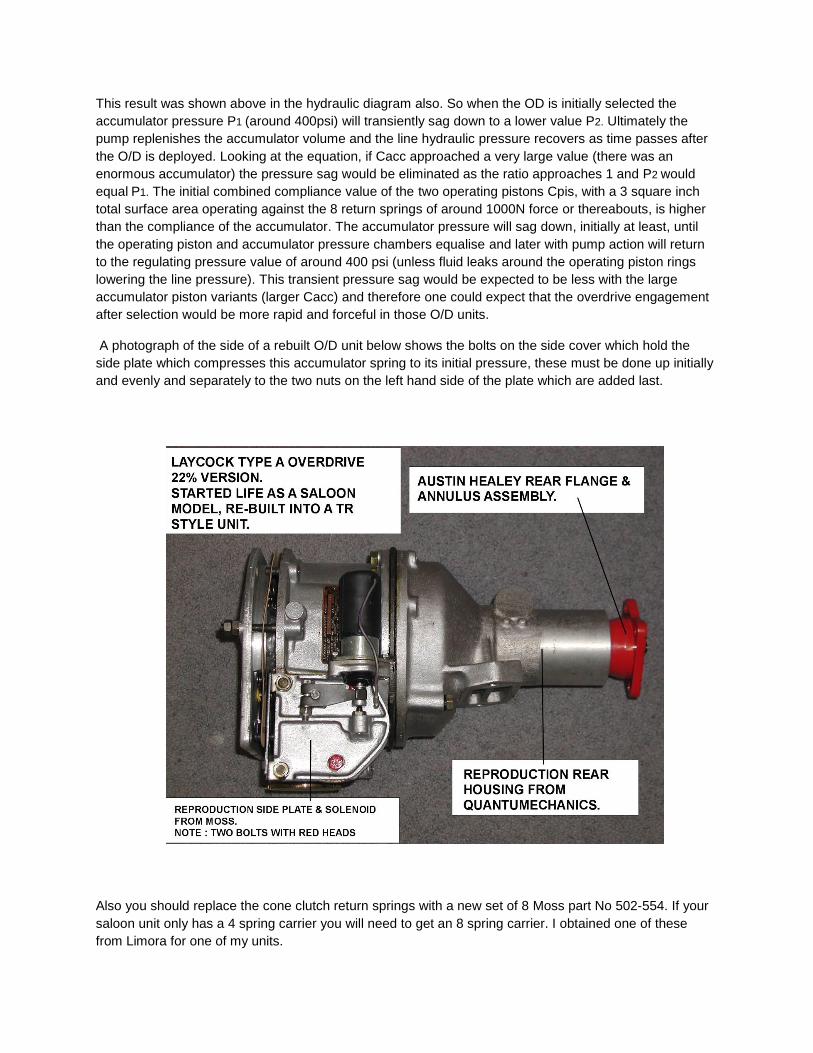
A photograph of the side of a rebuilt O/D unit below shows the bolts on the side cover which hold the
side plate which compresses this accumulator spring to its initial pressure, these must be done up initially
and evenly and separately to the two nuts on the left hand side of the plate which are added last.
Also you should replace the cone clutch return springs with a new set of 8 Moss part No 502-554. If your
saloon unit only has a 4 spring carrier you will need to get an 8 spring carrier. I obtained one of these
from Limora for one of my units.

It is best to fit the original tail housing to the O/D and to keep the rear mount standard. When I acquired
my TR4A it had a non standard rear mount to adapt the saloon O/D unit, this also caused problems with
the central exhaust pipe mounting (wasn’t there!) In addition the speedometer was reading abominably
low due to the 3.5 ratio pinion speedo drive. Re-manufactured type A O/D tail housings of outstanding
quality are available from Quantumechanics.
The photo below shows some useful tools for rebuilding an O/D. It is best to make a tool to hold the O/D
rear flange while the rear nut is being undone or done up. This is made out of a piece of angle iron and
held to the flange with two driveshaft bolts. These large rear nuts can be very tight and need a power bar
to undo them. The original nuts had a split pin. Replacement nylock nuts are available from Moss.
Without the angle iron tool, the flange might be held in a vice, but this can mark and damage it. A puller is
sometimes needed to extract the flange from the annulus shaft as the splines in some cases can be an
interference fit.
An improvised tool is useful to remove the accumulator piston housing if you don’t have the correct
Laycock tool. Using a machined piece of wood provides a good grip and no chance of damaging the bore
of the accumulator piston housing. The special overdrive drain nut remover tool is essential to avoid
damage to the large brass nut.

If the Gearbox and O/D are being rebuilt it is sensible to rebuild the O/D first as the gearboxes main-shaft
is a useful alignment tool for the O/D unit. The photo of the unit below is the one that I installed in my
TR4A:
When the overdrive has been rebuilt with new O rings, thrust washers, gaskets etc and has been re-
attached to the gearbox it is well worth testing the unit before installing it in the car. Any problems are
better dealt with prior to installation. This can be done with a test rig made with a 1 HP 2800 RPM single
phase AC motor and a wooden frame. I adapted an old clutch plate and made a coupler to rotate the
gearbox input shaft .The O/D is checked with the G/Box in 4th gear and an input RPM near 2800. This
way the O/D’s hydraulic pressure and function can be tested before fitting the unit back into the car:

The pressure gauge is adapted into a spare operating valve cover nut so the function of the valve is not
affected. When you initially re-fill the G/Box with oil, wait at least 1/2 hr for the oil to migrate into the O/D
unit before testing:
The following photos show aspects of the restoration of my TR4A G/Box and O/D. I would recommend
the use of a puller for the G/Box bearings as above. The minimum special tool required for the O/D unit is
for grabbing hold of and extracting the accumulator’s piston housing as shown in a photo above.
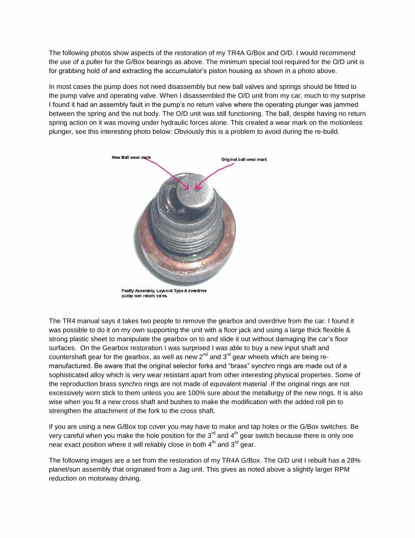
In most cases the pump does not need disassembly but new ball valves and springs should be fitted to
the pump valve and operating valve. When I disassembled the O/D unit from my car, much to my surprise
I found it had an assembly fault in the pump’s no return valve where the operating plunger was jammed
between the spring and the nut body. The O/D unit was still functioning. The ball, despite having no return
spring action on it was moving under hydraulic forces alone. This created a wear mark on the motionless
plunger, see this interesting photo below: Obviously this is a problem to avoid during the re-build.
The TR4 manual says it takes two people to remove the gearbox and overdrive from the car. I found it
was possible to do it on my own supporting the unit with a floor jack and using a large thick flexible &
strong plastic sheet to manipulate the gearbox on to and slide it out without damaging the car’s floor
surfaces. On the Gearbox restoration I was surprised I was able to buy a new input shaft and
countershaft gear for the gearbox, as well as new 2nd
and 3rd
gear wheels which are being re-
manufactured. Be aware that the original selector forks and “brass” synchro rings are made out of a
sophisticated alloy which is very wear resistant apart from other interesting physical properties. Some of
the reproduction brass synchro rings are not made of equivalent material .If the original rings are not
excessively worn stick to them unless you are 100% sure about the metallurgy of the new rings. It is also
wise when you fit a new cross shaft and bushes to make the modification with the added roll pin to
strengthen the attachment of the fork to the cross shaft.
If you are using a new G/Box top cover you may have to make and tap holes or the G/Box switches. Be
very careful when you make the hole position for the 3rd
and 4th gear switch because there is only one
near exact position where it will reliably close in both 4th and 3
rd gear.
The following images are a set from the restoration of my TR4A G/Box. The O/D unit I rebuilt has a 28%
planet/sun assembly that originated from a Jag unit. This gives as noted above a slightly larger RPM
reduction on motorway driving.


Finally I found it was quite helpful when reassembling the gearbox to wire the gear cluster together to
stop it coming apart during insertion.
*****************************************************************************************************************