laxpc instrument on astrosat : physics in its design p.c...
TRANSCRIPT

LAXPC Instrument on ASTROSAT : Physics in Its Design
P.C. AgrawalUM-DAE Center of Excellence for Basic Sciences
Mumbai


When an X-ray photon interacts with matter, four major processes of interaction are possible :
(1) the Photoelectric Effect,
(2) Coherent Scattering ( or Thomson Scattering ) (3) Incoherent (or Compton) Scattering, and
(4) Pair Production.
The photoelectric effect corresponds to absorption and is dominant in 0.1- 100 keV
Coherent scattering and incoherent scattering contribute to a beam’s attenuation by scattering the incident photons with and without energy change, respectively.

Coherent scattering major contributor at less than 50 keV for high Z materials
Compton scattering is almost independent of photon energy and transfers part of E x to the scattered e --
For measuring energy of incident X-ray photon of < 100 keV, Photoelectric Process is the preferred interaction

The photoelectric effect is the process by which an incident photon of energy Ex interacts with an orbital electron and ejects several fluorescent photons and an orbital electron.
The e -- must have binding energy E e < E x The Incident photon is absorbed by the atom and loses all its energy. Electron is ejected , usually from the K or L shell, leaving a hole in that shell.
Now the atom is ionized and is in an excited state.
For low energy x-rays, the photoelectric effect is the dominant process. E KE = E x - E e
Photoelectric Effect

The PE cross-section is approximated by
Where Z = Atomic Number of element , E = Energy of the photon
σ PE = in barn

When a beam of x-rays of energy E and initial intensity l 0 traverses through a material of thickness t, its intensity l is reduced exponentially
μ is Linear Absorption Coefficient related to intensity l by

Linear Attenuation Coefficient ( µ ) ( 1/ cm)
Probability of interaction of photon in traversing unit length of matter
µ depends on photon energy E and Z of material
Mass Absorption Coefficient (µ / ρ) (g / cm ²) :
Absorption probability of interaction in gm / cm ² of matter
Surface density : ρ X length

Mass absorption coefficient of Xenon Vs Energy

General Requirements of Good X-ray Detectors
• High Detection Efficiency
σ ~ Z 4 / E 3
• Wide Spectral Response • Good Energy Resolution• Operation preferably at normal temperature• Ruggedized for Space Environment
• Inexpensive and easy to make large area arrays

Non-Imaging X-ray Detectors
Ionization potential of gases (Ar, Xe etc) ~ 12 eV
Half of Energy lost in non-ionizing collision
Energy / ē-ion pair ~ 25 eV
Detector W(eV)
Pcs ~ 25
NaI, CsI ~ 1000
Si(Li) ~ 4
CdTe/CZT ~ 5 eV
NaI/CsI only useful at E > 15 keV
CdTe/CZT operate at E > 15 keV at 0 to-10 degree C
Si(Li) operates at E > 2 keV at 100 k (LN temp)
Si (drift) operates at E > 1 keV , Moderate cooling

Detector Characteristics for Timing and Spectral Studies
High count rate needed to measure kHz scale variability implying large photon collecting area. Time tagging of each genuine X-ray event to 10 µsec accuracy to measure high frequency variability.
Must have Broad spectral response and high detection efficiency in 2-100 keV.
Stable HV (< 0.2%) which is controllable and can be varied in coarse of fine steps to control gas gain of PCs in the event of development of gas leak.

Reasonably good energy resolution to measure continuum and line spectra with no significant degradation with time. This needs monitoring of gas gain and E. Resolution in orbit.
High efficiency for rejecting non-cosmic X-ray events caused by interactions of cosmic rays and high energy photons ( > 100 keV) in the detector volume and its walls.
Why Proportional Counter as detector of choice ? • PC chosen as its technology well proven. one can
design and make large area detectors with multiple units to provide redundancy. TIFR group successfully developed Xenon-filled PCS of ~ 2500 cm² area and used successfully in several balloon experiments.
• Difficult to achieve Energy threshold of < 15 keV with large array CdTe/ CZT detectors as seen in INTEGRAL and SWIFT. Energy threshold of ~ 2 keV essential as most photons from cosmic sources in 2-15 keV.
• Silicon Drift detectors still in small size and not certain whether large arrays can be made with E < 2 keV.
Realization of High Detection Efficiency
Xenon (Z=54) Chosen as filling gas. Gas pressure 2 atmosphere to achieve higher detection efficiency at higher Energy.
15 cm deep X-ray detection volume divided into 5 layers each 3 cm deep.

Proportional Counters
• X-rays are detected through their interaction with inert gas in a windowed chamber
• Primary photoelectron is emitted by the photoelectric effect.• Secondary electrons are emitted in a localized cloud by primary electrons in very high field region
E = V / r ln ( b/a)
• Drift Region away from anode• Electron Multiplication within ~ a few wire radii
• Mean number of electrons released is N = E / w, where E is the energy of the X-ray, and w is the ionization energy of the gas: w = 26.2 eV for Ar; 21.5 eV for Xe.
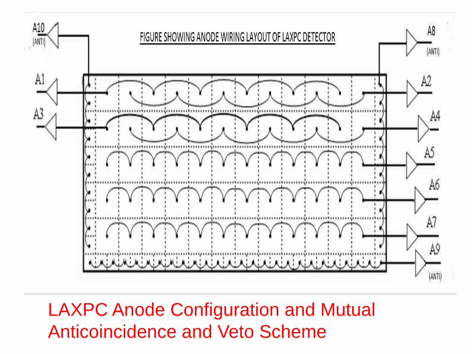
LAXPC Anode Configuration and Mutual Anticoincidence and Veto Scheme

LAXPC X-ray detector Anode Assembly with veto layer on 3 sides mounted on the back plate. 60 Anode cells are arranged in 5 layers to make the X-ray detection volume. 37 Micron dia. Au-plated SS wires under tension used for anodes.
• LAXPC has high detection efficiency up to ~ 80 keV ( > 50 % upto 70 keV)
• Deep Detector (15 cm arranged in 5 layers each 3 cm deep vs 3.3 cm for
the PCA on RXTE
• Xenon filled at a pressure of 2 atmosphere

Why Very Stable HV Supply (<0.2 % variation) ?
The gas gain of LAXPC depends, on the nature of the filling gas, gas pressure, anode and cathode radii and applied voltage. For counter of a given geometry and for a particular filling gas it varies rather strongly with the gas pressure and the high voltage applied to the anode wire.
For a given gas filled at a specified pressure, a small variation of gas gain (Δ G/G) with small change in the applied voltage (ΔV/V) can be represented by the relation (Δ G/G) ≈ A (Δ V/V)Where A is a constant in the range of ≈ 10 to 15 which is different for different gas mixtures.

The stability of gas gain, therefore, requires that the high voltage applied to the anodes be kept constant. with a variation of ≤ 0.2 percent with temperature (+10º C to +30º C range) or load variation.

Why Gas Pressure should remain Steady ?The gas gain also depends critically on the gas pressure P and varies with P in an exponential manner. Over a small range of pressure variation (Δ P/P) the gas gain variation can be represented as follows :
(Δ G/G) ≈ B (Δ P/P)
where B = 5-15 is a constant which depends on gas mixture.
It needs to be clarified that the collision mean free path and, therefore, gas gain depends on the gas density and not the pressure which varies with temperature for a sealed volume. Variation of gas pressure with the temperature does not affect the gas gain so long as the density is kept constant.

What determines Spectral Response Band ?
X-ray entrance window ,which also serves as gas barrier, is 50 µ thick Aaluminized Mylar film which absorbs X-rays below 3 keV.
Detection efficiency becomes low for X-rays of > 100 keV.

0
1000
2000
3000
4000
5000
6000
7000
10 20 30 40 50 60 70 80 90 100
Layer-wise Effective Area of ASTROSAT LAXPC
totallayer 1layer 2layer 3layer 4layer 5

Restoration of Energy Resolution before and after Launch :
An on board Gas Purifier Unit designed and installed as integral part of each LAXPC to restore energy resolution.
Based on forced circulation of Xenon through an OxisorbCartridge (filled with zeolite like chemical) which removes water, O and C0-2 molecules. A motor driven Bellow pump activated on command for this.
Entire gas volume of 80 litres circulated in about an hour and in a few hours original R restored.
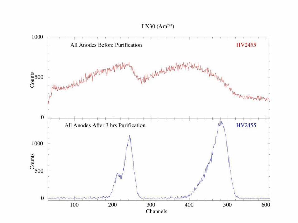

How to Monitor Energy Resolution in Orbit ?
A collimated Am-241 source that produces 59.6 keV line in a Fan shaped beam, shines only on one end-Veto layer producing a few counts per sec.
PHA analysis of Veto-layer counts done to record the energy spectrum of the line and value of R is continuously measured.
If R degrades by more than a TBD value, Purifier pump is commanded to operate.
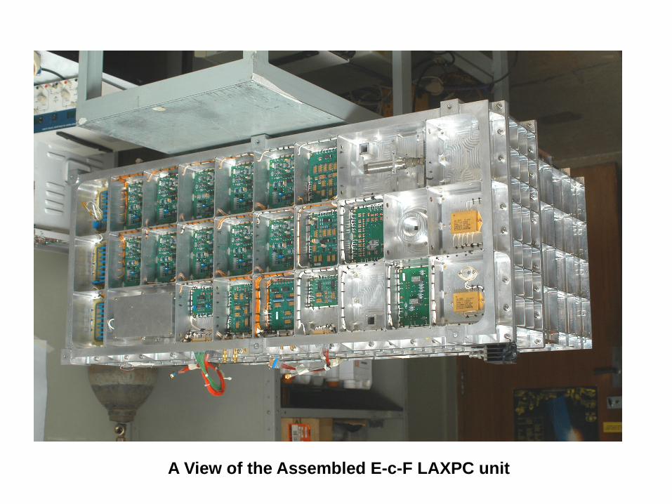
A View of the Assembled E-c-F LAXPC unit

00v
200
LX10 Anode A8 on 19 -10 -:
200 400
A10 Anode A8 on 28- 11 -20:
400
Channels
2015
.2 % at 30 keV
% at 60 keV.4
600 800
15 (After 4 Hours Purificatiot
11.26 % at 30 keV
9.41 % at 60 keV
600 800
NO
618
1 =
I'LE =
MO
'
9
81.
,06
£ =N
O'
1
EE
CE
Z =
MO
=00
Z
910
,K =
Nd
9.1
LI*T.0-=N
1
0
'0SO
=A
I
AN
C 4
,4 =N
D
50.3
096
6E
=
Z1
,1
9
T6
E .D
D
=
ND
609.6
,ND
.
Z.661 -D.`J
OW
,9
,r
1
9
Z.Z
. ,N
9
6
TE
E.0
-,,` 6.B
E

Selection of Genuine X-ray events :
Energy should be in 3-80 keV only.
The event should be only from a single anode layer unaccompanied by a Veto layer event.
If there are signals from two anode layer simultaneously, they are rejected except when energy of one of the event falls in the K-band ( set values generally in 27-33 kev band ). This happens when Xenon K-fluorescent photon is absorbed in a different anode layer than the one in which it originated. These are genuine X-ray events.
All events which produce mutual anticoincidence between any of the 7 anode signals are rejected.

Charged particles travel through more than one anode layer producing double or multiple events and hence most such events are rejected.
Compton scattering of high energy photons dominant source of background as in Compton scattering there is a continuous distribution of electron energy and many appear like genuine X-ray events.
Cosmic ray and Gamma-ray interactions in the detector walls or gas volume mostly rejected as either enrgy exceeds 80 keV or they produce Veto events or mutial anti events.

10
1 L
T 10 °C
t 20 °C30 °C
- y- 10 °C with peak alignment correction
-*- Single anode at room temperature
10 20 30 40
Energy (Ec; keV)
50 60

Window Support Collimator
• Mechanical Collimator defines field of View• Usually honeycomb shape• A θ / A 0 = ( 1 – tan θ / tan θ x ) ( 1 – tan θ / tan θ y )• Graded shield Collimator for Hard X-rays Tin + Cu + Al or Pb + Sn + Cu
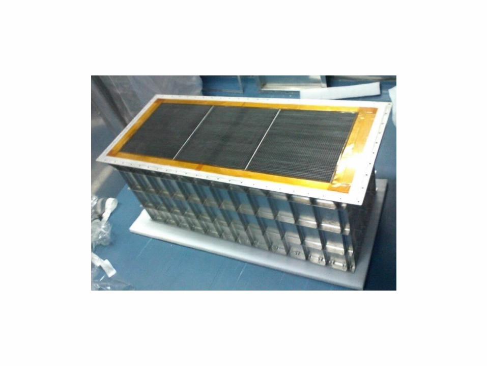

Total thickness of FOVC slats = 175 µ
Slits cut in slats every 6.5 mm by laser cutting and slats crossed and assembled to make honey comb shaped FOVC