lava lamp 2.0 : the inductioning - university of illinois
TRANSCRIPT

Lava Lamp 2.0 :
The Inductioning
ECE 445 - Senior Design Laboratory
Design Review
Team 44:
Erik Eldridge Jake Lawrence
Ignacio Iber
TA: Daniel Frei

Contents
Introduction 3
1.1 Objective 3
1.2 Background 3
1.3 High-level requirement list 3
Design 4
2.1 Block Diagram 4
2.2 Physical Design 5
2.3 Block Design 6
2.4 Schematics 8
2.5 Requirements and Verifications 12
2.6 Supporting Material 15
2.7 Tolerance Analysis 16
Cost and Schedule 17
3.1 Cost Analysis 17
3.2 Schedule 18
Ethics and Safety 19
4.1 Ethical issues from the IEEE Code of Ethics[2] 19
4.2 Safety considerations 19
Citations 21
Pg. 2
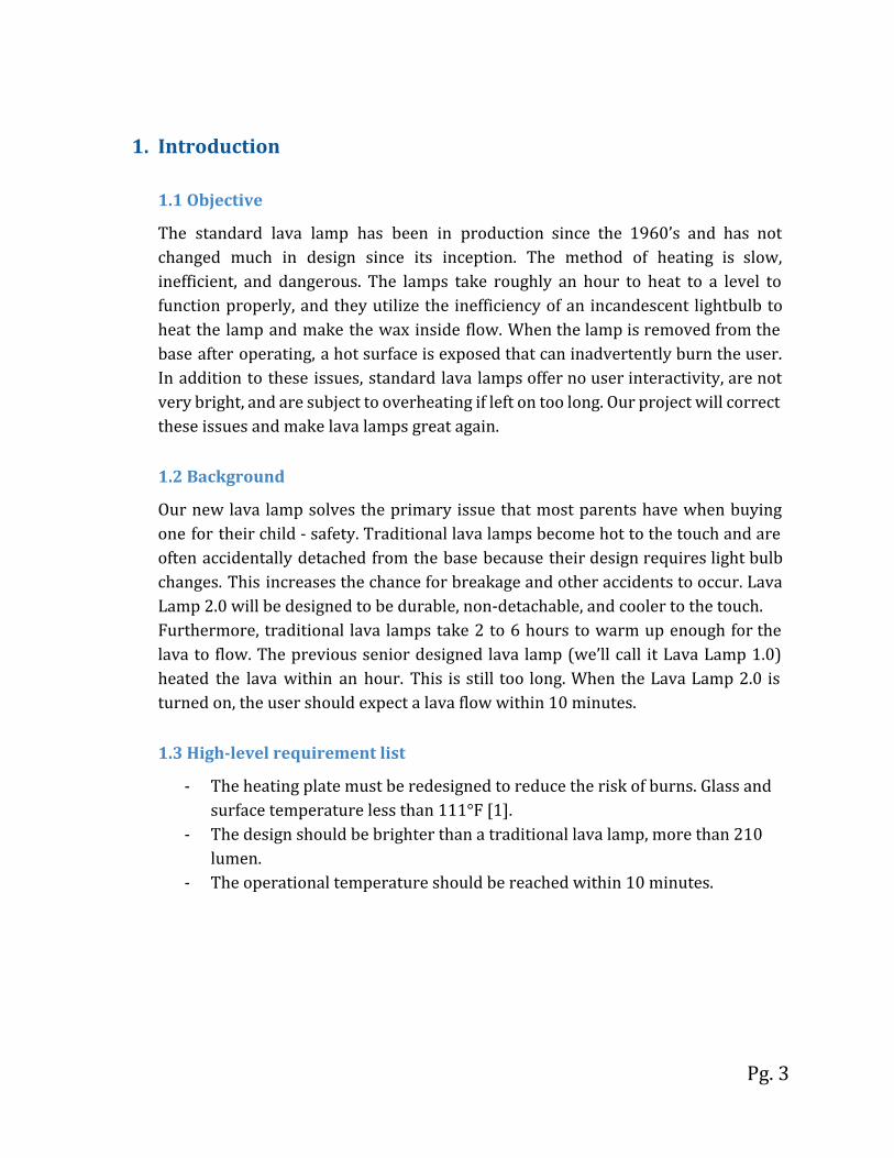
1. Introduction
1.1 Objective
The standard lava lamp has been in production since the 1960’s and has not changed much in design since its inception. The method of heating is slow, inefficient, and dangerous. The lamps take roughly an hour to heat to a level to function properly, and they utilize the inefficiency of an incandescent lightbulb to heat the lamp and make the wax inside flow. When the lamp is removed from the base after operating, a hot surface is exposed that can inadvertently burn the user. In addition to these issues, standard lava lamps offer no user interactivity, are not very bright, and are subject to overheating if left on too long. Our project will correct these issues and make lava lamps great again.
1.2 Background
Our new lava lamp solves the primary issue that most parents have when buying one for their child - safety. Traditional lava lamps become hot to the touch and are often accidentally detached from the base because their design requires light bulb changes. This increases the chance for breakage and other accidents to occur. Lava Lamp 2.0 will be designed to be durable, non-detachable, and cooler to the touch. Furthermore, traditional lava lamps take 2 to 6 hours to warm up enough for the lava to flow. The previous senior designed lava lamp (we’ll call it Lava Lamp 1.0) heated the lava within an hour. This is still too long. When the Lava Lamp 2.0 is turned on, the user should expect a lava flow within 10 minutes.
1.3 High-level requirement list
- The heating plate must be redesigned to reduce the risk of burns. Glass and surface temperature less than 111°F [1].
- The design should be brighter than a traditional lava lamp, more than 210 lumen.
- The operational temperature should be reached within 10 minutes.
Pg. 3

2. Design
2.1 Block Diagram
Figure 1: Block Diagram
Our lava lamp consists of 5 well differentiated parts + the input, shown in Figure 1. The power system supplies AC and DC power to the elements that transform energy (energy system) and to the PCB (control system). The PCB is in charge of controlling the amount of power delivered, as it receives feedback from our measurement system. This measurement system will include a temperature sensor to prevent overheating. The energy system is made up of the induction coil, the workpiece and the multicolor LED’s.
We can fulfill our 3 high level requirements because the heat flow will only occur inside the glass, the LEDs can be as bright as a traditional lava bulb, and the induction will lead to faster heating.
Pg. 4

2.2 Physical Design
Figure 2: Physical Design
Above is a first sketch of what our design will look like. Induction heating allows us to achieve a faster and more energy efficient heat transfer, as the induction coil and workpiece are held close to each other. This also leaves space around them to place our LED lights, and in the bottom of the glass we
Pg. 5
can measure the temperature, which will be correlated to the current flowing through our coil, and thereby controlled by the MCU.
2.3 Block Design
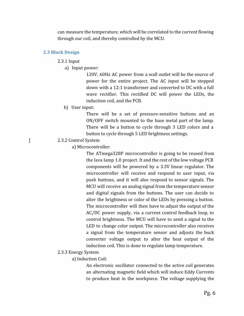
2.3.1 Input a) Input power:
120V, 60Hz AC power from a wall outlet will be the source of power for the entire project. The AC input will be stepped down with a 12:1 transformer and converted to DC with a full wave rectifier. This rectified DC will power the LEDs, the induction coil, and the PCB.
b) User input: There will be a set of pressure-sensitive buttons and an ON/OFF switch mounted to the base metal part of the lamp. There will be a button to cycle through 3 LED colors and a button to cycle through 5 LED brightness settings.
] 2.3.2 Control System a) Microcontroller:
The ATmega328P microcontroller is going to be reused from the lava lamp 1.0 project. It and the rest of the low voltage PCB components will be powered by a 3.3V linear regulator. The microcontroller will receive and respond to user input, via push buttons, and it will also respond to sensor signals. The MCU will receive an analog signal from the temperature sensor and digital signals from the buttons. The user can decide to alter the brightness or color of the LEDs by pressing a button. The microcontroller will then have to adjust the output of the AC/DC power supply, via a current control feedback loop, to control brightness. The MCU will have to send a signal to the LED to change color output. The microcontroller also receives a signal from the temperature sensor and adjusts the buck converter voltage output to alter the heat output of the induction coil. This is done to regulate lamp temperature.
2.3.3 Energy System a) Induction Coil:
An electronic oscillator connected to the active coil generates an alternating magnetic field which will induce Eddy Currents to produce heat in the workpiece. The voltage supplying the
Pg. 6

coil will be determined by the MCU, which will react based on info received from the temperature sensor. The MCU will alter the value on a digital potentiometer to adjust the resistor divider on the feedback loop of the buck converter. Altering the feedback loop will drive the output voltage lower or higher, depending on the MCU instruction.
b) Workpiece (passive coil): The workpiece is the electromagnetic metal plate attached to the bottom of the lamp that is heated by a flat induction coil. This, in turn, heats the liquid at the bottom of the lamp and causes the lava to flow.
c) Light System: A system of 6 multi-colored RGB LED’s will be mounted into the top of the metal base, adjacent to the induction coil. The bulbs will be CREE XLamp XM-L color LEDs. The LEDs receive PWM control signals from the microcontroller to determine color. They receive DC power from a 6 V output buck converter on the PCB, which in turn comes from the AC/DC converter.
2.3.4 Measurement System a) Temperature sensor:
The TMP36 temperature sensor will be mounted to the outside of the glass just below the induction chamber. This is the hottest part of the lava lamp besides the conductor itself, however this area is not accessible to touch. The sensor will take a continuous analog temperature reading from this area and provide continuous feedback to the control system via a voltage signal to the MCU. This information will be used to regulate the output of the induction circuit and make sure that the lamp doesn’t get too hot.
2.3.5 Power System a) AC/AC converter:
The AC/AC converter is a FD8-10 transformer. It has a 12:1 turns ratio and will convert 120V, 60Hz input power from a wall outlet and reduce the voltage to 10V AC. this AC signal is later rectified by the AC/DC converter.
b) AC/DC power supply The AC/DC power supply will take 10V, 60Hz AC from the transformer secondary and converts it to DC using a full wave
Pg. 7
rectifier and filter capacitor. Supplied DC power will be inputs to the buck converters and linear regulator.
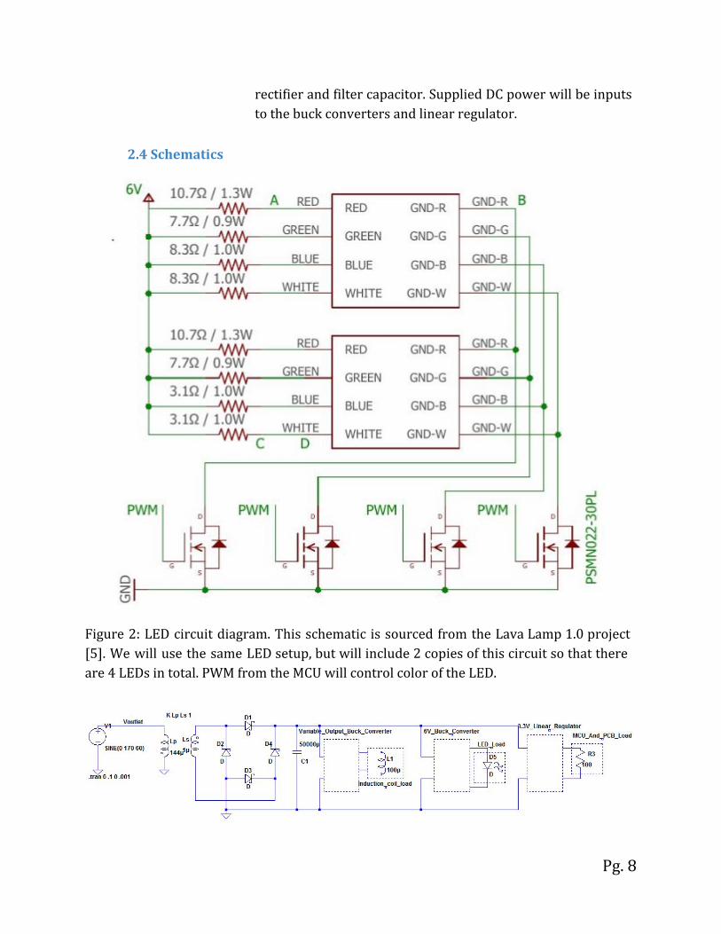
2.4 Schematics
Figure 2: LED circuit diagram. This schematic is sourced from the Lava Lamp 1.0 project [5]. We will use the same LED setup, but will include 2 copies of this circuit so that there are 4 LEDs in total. PWM from the MCU will control color of the LED.
Pg. 8

Figure 3: The above circuit depicts the power system for the lava lamp. V1 is input voltage from a standard wall outlet. This input voltage is stepped down to 10VAC using a 12:1, 100VA transformer. This 10VAC voltage is converted to DC by means of a full-wave rectifier and filter capacitor. The variable output buck converter will control voltage to the induction coil based on MCU instructions. The LEDs and MCU will need a fixed 6V output buck converter and a fixed output linear regulator respectively to further step down the DC voltage.
Figure 4. Sample circuit setup for our induction heating coil sourced from Swagalam Innovations. Although some research still has to be done in terms of how the inductive coil circuit will look like, the idea is to simulate the induction cooktop circuit which can be found in a generic kitchen (Figure 4). The active coil will produce an electromagnetic field which will induce eddy currents in the passive coil.
Pg. 9

Figure 5. This is the basic circuit for the temperature sensor. It sends a voltage signal to the MCU which is proportional to the temperature being recorded. Only one temperature sensor is required for this design.
Figure 6. This is the microcontroller circuit sourced from lava lamp 1.0 [5], but one temperature sensor has been removed.PWM signals from the MCU are used to control the LEDs. We will start with this circuit for a first revision and analyze it to find sources of noise. The second revision will add in extra filtering capacitors where needed.
Pg. 10
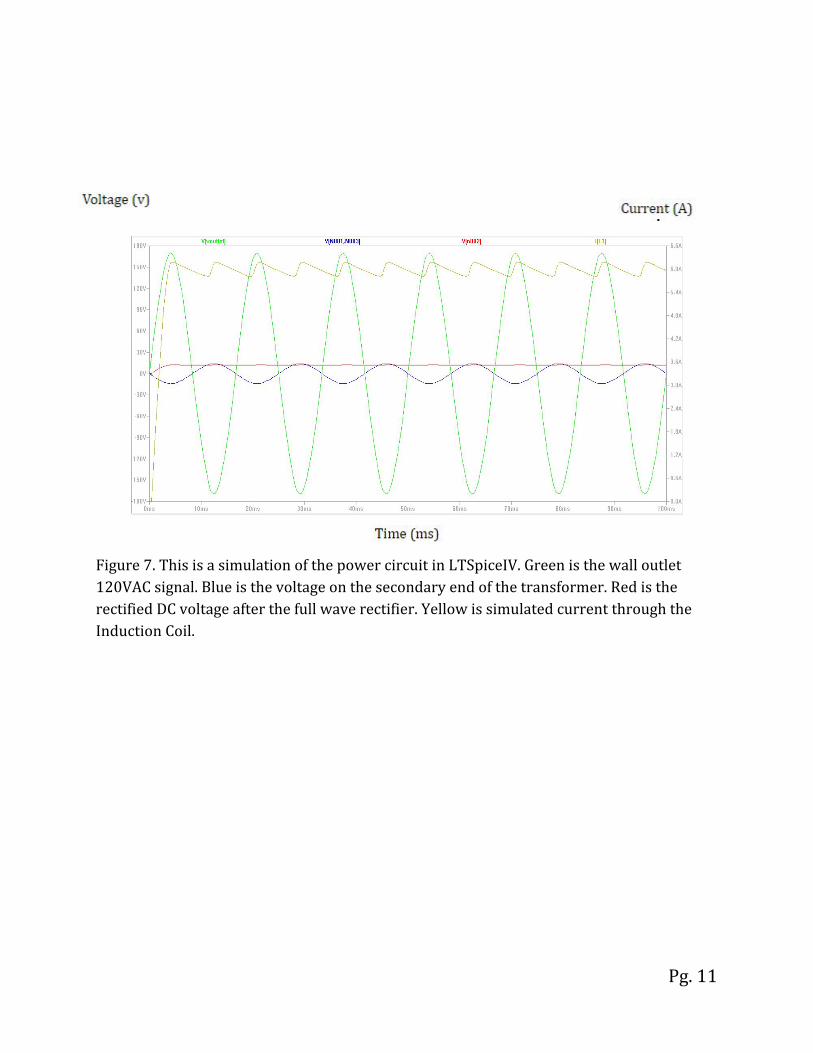
Figure 7. This is a simulation of the power circuit in LTSpiceIV. Green is the wall outlet 120VAC signal. Blue is the voltage on the secondary end of the transformer. Red is the rectified DC voltage after the full wave rectifier. Yellow is simulated current through the Induction Coil.
Pg. 11
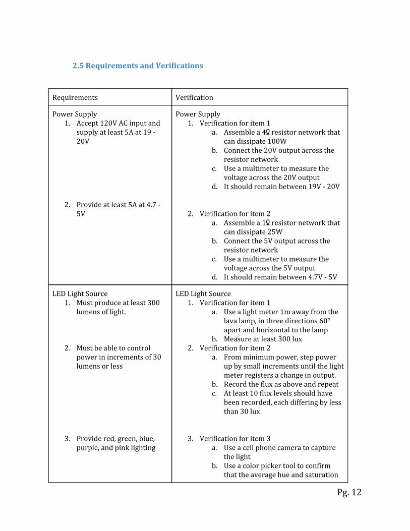
2.5 Requirements and Verifications
Requirements Verification
Power Supply 1. Accept 120V AC input and
supply at least 5A at 19 - 20V
2. Provide at least 5A at 4.7 - 5V
Power Supply 1. Verification for item 1
a. Assemble a 4Ω resistor network that can dissipate 100W
b. Connect the 20V output across the resistor network
c. Use a multimeter to measure the voltage across the 20V output
d. It should remain between 19V - 20V
2. Verification for item 2 a. Assemble a 1Ω resistor network that
can dissipate 25W b. Connect the 5V output across the
resistor network c. Use a multimeter to measure the
voltage across the 5V output d. It should remain between 4.7V - 5V
LED Light Source 1. Must produce at least 300
lumens of light.
2. Must be able to control power in increments of 30 lumens or less
3. Provide red, green, blue, purple, and pink lighting
LED Light Source 1. Verification for item 1
a. Use a light meter 1m away from the lava lamp, in three directions 60° apart and horizontal to the lamp
b. Measure at least 300 lux 2. Verification for item 2
a. From minimum power, step power up by small increments until the light meter registers a change in output.
b. Record the flux as above and repeat c. At least 10 flux levels should have
been recorded, each differing by less than 30 lux
3. Verification for item 3 a. Use a cell phone camera to capture
the light b. Use a color picker tool to confirm
that the average hue and saturation
Pg. 12
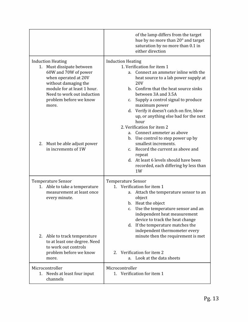
of the lamp differs from the target hue by no more than 20° and target saturation by no more than 0.1 in either direction
Induction Heating 1. Must dissipate between
60W and 70W of power when operated at 20V without damaging the module for at least 1 hour. Need to work out induction problem before we know more.
2. Must be able adjust power in increments of 1W
Induction Heating 1. Verification for item 1
a. Connect an ammeter inline with the heat source to a lab power supply at 20V
b. Confirm that the heat source sinks between 3A and 3.5A
c. Supply a control signal to produce maximum power
d. Verify it doesn’t catch on fire, blow up, or anything else bad for the next hour
2. Verification for item 2 a. Connect ammeter as above b. Use control to step power up by
smallest increments. c. Record the current as above and
repeat d. At least 6 levels should have been
recorded, each differing by less than 1W
Temperature Sensor 1. Able to take a temperature
measurement at least once every minute.
2. Able to track temperature to at least one degree. Need to work out controls problem before we know more.
Temperature Sensor 1. Verification for item 1
a. Attach the temperature sensor to an object
b. Heat the object c. Use the temperature sensor and an
independent heat measurement device to track the heat change
d. If the temperature matches the independent thermometer every minute then the requirement is met
2. Verification for item 2 a. Look at the data sheets
Microcontroller 1. Needs at least four input
channels
Microcontroller 1. Verification for item 1
Pg. 13

2. Needs at least five output channels
3. Needs at least 20kB of memory
4. Needs a clock of at least 20 MHz
5. Needs to be able to run on 5V±1V
a. Verify with the datasheet
2. Verification for item 2 a. Verify with the datasheet
3. Verification for item 3 a. Verify with the datasheet
4. Verification for item 4 a. Hook up the clock pin to the
oscilloscope positive terminal and ground to the ground terminal
b. Measure the clock frequency
5. Verification for item 5 a. Verify with the datasheet
Control 1. Rise time of 10 minutes for
the lava globules from room temperature.
2. System able to handle temperatures up to 200°F at the base of the glass without damage.
Control 1. Verification for item 1
a. Measure glass temperature and
make sure it is at 70°F (± 3°F) b. Start the lava lamp and begin a
stopwatch. c. If the lava moves before 10 minutes
the requirement is met.
2. Verification for item 2 a. Alter the control system to allow
base temperatures of 200°F. b. Start the lava lamp and monitor the
temperature feedback via on board display.
c. If the system holds a temperature of 200°F the requirement is met.
On-Unit Input On-Unit Input 1. Verification for item 1
Pg. 14
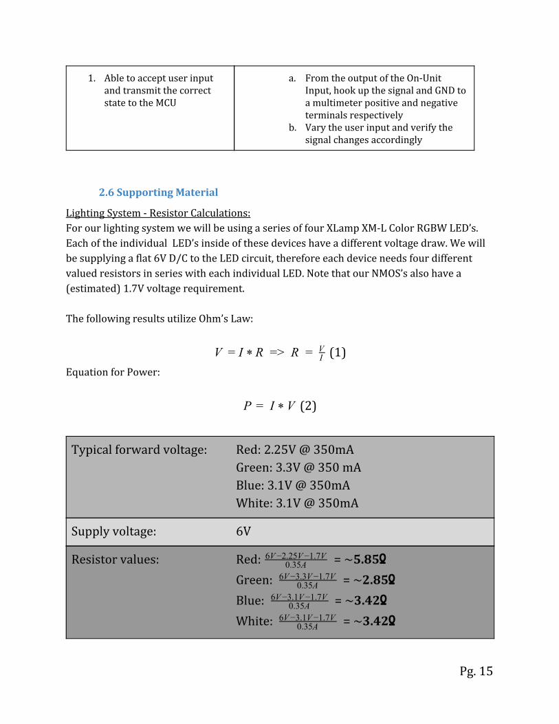
1. Able to accept user input and transmit the correct state to the MCU
a. From the output of the On-Unit Input, hook up the signal and GND to a multimeter positive and negative terminals respectively
b. Vary the user input and verify the signal changes accordingly
2.6 Supporting Material
Lighting System - Resistor Calculations: For our lighting system we will be using a series of four XLamp XM-L Color RGBW LED’s. Each of the individual LED’s inside of these devices have a different voltage draw. We will be supplying a flat 6V D/C to the LED circuit, therefore each device needs four different valued resistors in series with each individual LED. Note that our NMOS’s also have a (estimated) 1.7V voltage requirement. The following results utilize Ohm’s Law:
(1) > R V = I * R = = I
V
Equation for Power:
(2)IP = * V
Typical forward voltage: Red: 2.25V @ 350mA Green: 3.3V @ 350 mA Blue: 3.1V @ 350mA White: 3.1V @ 350mA
Supply voltage: 6V
Resistor values: Red: = ~5.85Ω0.35A6V−2.25V−1.7V
Green: = ~2.85Ω0.35A6V−3.3V−1.7V
Blue: = ~3.42Ω0.35A6V−3.1V−1.7V
White: = ~3.42Ω0.35A6V−3.1V−1.7V
Pg. 15

Power requirements: Red: 2.05V*0.35A = ~0.72W Green: 1V*0.35A = ~0.35W Blue: 1.2V * 0.35A = ~0.42W White: 1.2V * 0.35A = ~0.42W
Power system - Filter Capacitor Calculation
We performed a series of calculations in order to determine the correct filter capacitor
value for our AC/DC converter. It is known that capacitor charge is related to capacitor
current and half-cycle time by
Q=I*t (3)
It is also known that capacitor charge is related to capacitance and voltage drop by
Q=C*ΔV (4)
Combining these two equations yields the following equation. Assuming a 7A current draw, a half cycle time of 8.3ms, and a voltage drop allowance of 1V, we calculated the value of the filter cap to be
(5)C = I t*ΔV
= 0.056F = 56000uF17 0.008*
2.7 Tolerance Analysis
Confirming the tolerance of our induction heating element is the most critical component of our project. This is because proper implementation of the heating element is required to verify the requirements of safety and control for our lava globe. Not only does the inductive circuit have to be functional and fit below the globe with room to spare for the LED circuit, it must be able to heat the above liquid evenly and consistently. Due to unknowns in variation of lava flow, the operational temperature will first be set at 140°F(±2°F). If the startup time is too slow or our lava flow is undesirable, we will experiment with increasing the operational temperature by 5°F for each successive test until the requirements are met.
Pg. 16

We will confirm this tolerance by turning on the lava lamp starting from room temperature, allowing it to reach the operational temperature, and monitoring the operating temperature for six consecutive hours. If the temperature stays within a four degree range without disrupting the lava flow then the tolerance of our induction heating circuit will be confirmed.
3. Cost and Schedule
3.1 Cost Analysis
Personnel
Assumed Starting Salary $70,000
Per Hour Rate $30
Total Hours (20 per week)(12 total weeks) 240
Personnel Cost (for 3 members) $21,600
Total Cost (12 week salary + personal cost) $42,215
Parts
transformer $20.23
Button $0.95
Potentiometer $2.85
DC/DC converters $4.60
Analog RGB Strip $19.95
Temperature Sensor $2.27
ATmega328P $2.00
Lava Lamp $21.99
Miscellaneous PCB components $30.00
Total Parts Cost $104.84
Pg. 17
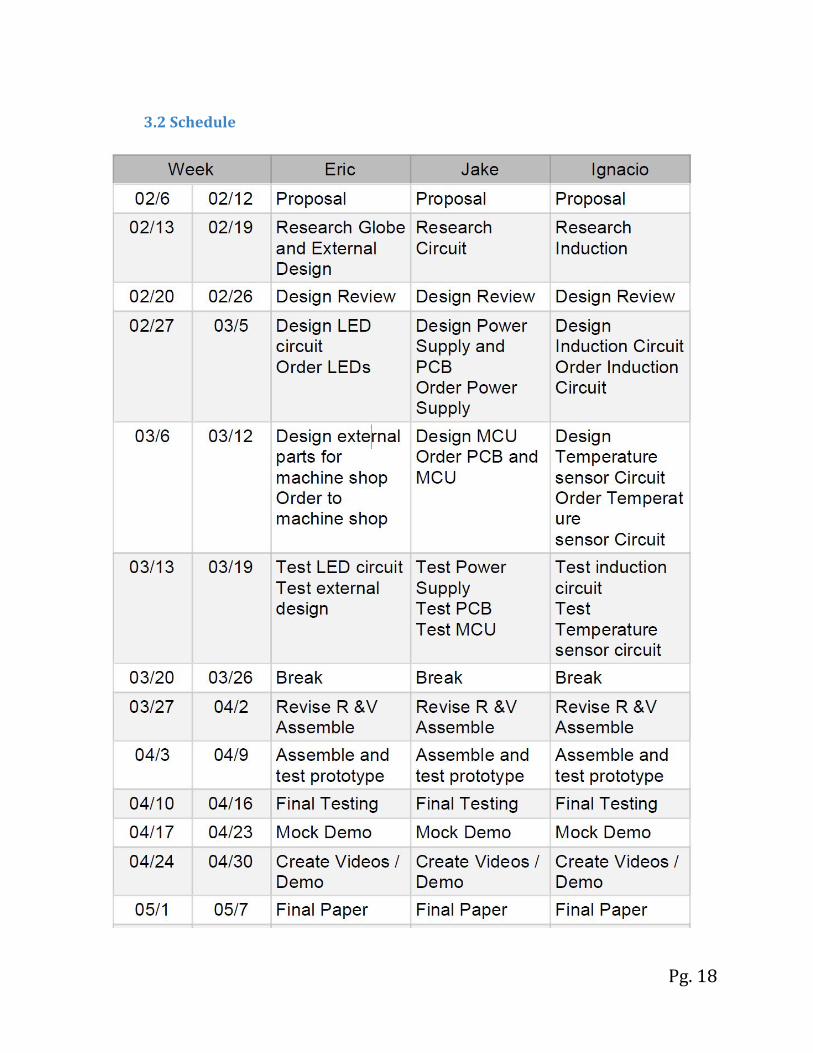
3.2 Schedule
Pg. 18
4. Ethics and Safety
4.1 Ethical issues from the IEEE Code of Ethics[2]
- “To be honest and realistic in stating claims or estimates based on available data.” We will be sure the data we use is credible and real, and will not falsify our own.
- “To improve the understanding of technology; its appropriate application, and potential consequences.” We will always be mindful of the safety considerations below and will not use our lamp outside of its intended purpose.
- “To avoid injuring others, their property, reputation, or employment by false or malicious action.” We will give credit to all sources, and make sure our source information is accurately represented. Furthermore, we will not use others work without their permission.
4.2 Safety considerations
Safety is a big concern for us and is at the forefront of our project requirements. When designing a lava lamp with a new inductive heating circuit we must be mindful of electrical, chemical, and thermal hazards.
When developing our system we must follow certain safety procedures to avoid danger of electric shock. We will work at a lab bench when testing our circuit at all times. Before adjusting any circuit we will make sure to unplug all power sources and test any electrical leads for current with a multimeter. We will make sure our circuits are properly grounded at all times. Finally, we will test our power system with an oscilloscope before connecting to our control and energy systems.
The composition of the wax inside of our lava globe presents a chemical hazard. While the chemical formula of the LAVALITE® MOTION LAMP is a trade secret, the official US Patent for lava lamps states that the wax contains a chemical called carbon tetrachloride[3]. Carbon tetrachloride causes eye, skin, ingestion, and respiratory irritation so we must wear gloves when handling the wax at all times and avoid ingestion. The lab safety document for carbon tetrachloride is provided below[4]. If the wax inside is replaced with our own formula we must adhere to proper safety procedures for any chemicals involved according to the OSHA guidelines.
Pg. 19

The induction system and heated glass also presents a thermal hazard, as well as a physical hazard from the risk of explosion. Temperatures of greater than 118°F on the external surface of the lamp will cause burns when touched [1], and excessively high temperatures on the bottom surface the glass may cause it to fracture or even explode. This is why our design features a temperature feedback system to keep the external glass below this temperature, keeping users safe. To ensure safety for the designers, preliminary thermal tests will be run on the power system to make sure internal components do not overheat. Then, the power system will be joined to the temperature system and additional testing will be performed to guarantee proper feedback before heating the lava globe. If at any time during testing the temperature feedback fails or rises above the desired temperature, a group member will be ready to manually disconnect power from the induction system.
Pg. 20

5. Citations
[1] Fire Dynamics. (2016, August 25). Retrieved from https://www.nist.gov/%3Cfront%3E/fire-dynamics [2] 7.8 IEEE Code of Ethics. (2017, February 24). Retrieved from http://www.ieee.org/about/corporate/governance/p7-8.html [3]Edward, Walker C. (1971). United States Patent 3,570,156. Retrieved from https://www.google.com/patents/US3570156 [4] Carbon tetrachloride Material Safety Data Sheet. (2008, February 6). Retrieved from http://fscimage.fishersci.com/msds/90116.htm [5] Frei, Daniel (2016, October 10). Retrieved from https://drive.google.com/drive/u/0/folders/0B01ptPIHjf4iZC1ZbDJaRmxsZlE
Pg. 21