launch dynamics of apfsds · pdf filelaunch dynamics of apfsds ammunition final 6. ... sctkmdt...
TRANSCRIPT
R - --- - -. x
LAUNCH DYNAMICS OF APFSDS AMMUNITION
Peter Plostins
October 1084 NOV 14 ' "A
r. g--" ,APPROVED FOR PUBUC RELEASE.; DISTRIBUTION UNUMITED.
US ARMY BALLISTIC RESEARCH LABORATORYABERDEEN PROVING GROUND, MARYLAND
84 11 05 090 (
N ,Destroy this report when it is no longer needed.Do not return it to the originator.
Additional copies of this report may be obtainedfrom the National Technical Information Service,U. S. Department of Commerce, Springfield, Virginia"N 22161.
The findings in this report are not to be construed as an officialDepartment of the Army position, unless so designated by otherauthorized documents.
The use of trade names or manufacturers' names in this reportdoes not constitute indorsement of any commercial product.
S.. . . . . ." .". .. ". , / . -
"pV
"" ~~UIN LA-'i• I r" I t U
"SECURITY CLASSIFICATION OF THIS PAGE ,•hen, Date Entered)
SREPORT DOCUMENTATION PAGE READ INSTRUCTIONSBEFORE COMPLETING FORM
I REPONT NUMBER 2. GOVT ACCESSION NO. 3. RECIPIENT'S CATALOG NUMBER
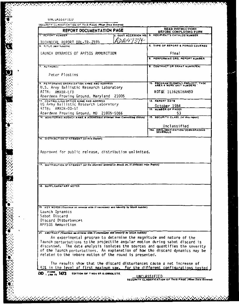
-- TECHNICAL REPORT BRL-TR-2595
4.Subtitle) TS TyPE OF REPORT & PERIOD COVERED
LAUNCH DYNAMICS OF APFSDS AMMUNITION Final6. PERFORMING ORG. REPORT NUMBER
"7. AUTHOR(A) S. CONTRACT OR GRANT NUMBER(&)
Peter Plostins
9. PERFORMING ORGANIZATION NAME AND ADDRESS 10. PROGRAM ELEMENT. PROJECT. TASK
U.S. Army Ballistic Research Laboratory AREA &WORK UNIT NUMBERS
"ATTN: AMXBR-LFD RDT&E 1L162618AH80Aberdeen Proving Ground, Maryland 21005
11. CONTROLLING OFFICE NAME AND ADDRESS 12. REPORT DATE
US Army Ballistic Research Laboratory October 1984-TTN; AMXDR-OD-ST 13. NUMBEROF PAGES
Aberdeen Proving Ground, MD 21005-5066 531 4. MONITORING AGENCY NAME &" ADDRESS(II dllfferet from Controlling Office) IS. SECURITY CLASS. (of thlis repott)
*6 Unclassified"S&. DECLASSIFICATION/DOWNGRADING
SCHEOULE
16. DISTRIBUTION STATEMENT (of this Report)
Approved for public release, distribution unlimited.
17. DISTRIBUTION STATEMENT (of the obetrtct •nteredln Block 20. If diffteret from Report)
, .. IS. SUPPLEMENTARY NOTES
19. KEY WORDS (Continue on revetse side If nacqseary and Identify by block ntuber)
Launch Dynamics.•Sabot Discard
Discard DisturbancesAPFSDS Ammunition
'20 ABSTRACT (Continesearevwog .td #ftrmrwewY aientifiy by block number)
An experimental program to determine the magnitude and nature of thelaunch perturbations to the projectile angular motion during sabot discard isdiscussed. The data analysis isolates the sources and quantifies the severityof the launch perturbations. An explanation of how the discard dynamics may be
N related to the inbore motion of the round is presented.
.,'-., The results show that the discard disturbances cause a net increase of41% in the level of first maximum yaw. For the different configurations tested
I JAN 73 14 n3 EDITON OFI NOV,6S IS OBSOLETE ,1N.1SSTFIF
SECUrRITY CLASSIFICATION OF THIS PAGE (1eno Dote Entered)
"%'•
• . , . .•: _ , - - - * - - . -- ,
I IUNCLASSIFIEDSECURITY CLASSIFICATION OF THIS PAOE1(WPIU Pat* Eiite.*)
20. ABSTRACT (Continued)'-_
chanqes in the inbore contribution to first maximum yaw indicate that thestr'uctur-al design of the front boreriding system is critical to the inborebehavior. A correlation is given between the angular rate to angle ratio at"the muzzle and the severity of the discard interaction's. Based on the correla-tion an alternate launch philosophy is necessary for APFSDS ammunition toassure on target accuracy.
%°%
S.'
'.l.
S.,.
,IJ"
S.-
6-'
S'.
S.o
-°S..
*4NLA•IFI
•fuNIYCLASS IFICAINOED S AEWe el ~tr#
• .5' •';, -.- ,: ., --. 'N ,X ;:-'.'- -•. . -- N ,' :..'-•-< -•-;. .'''-,: '-•,: % ; % - ' % " " " ,;
TABLE OF CONTENTS
Page
"LIST OF TLLUSTRATIONS................ ................... 5
• .- 1. INTRODUCTION ......... ........ . . . .. . . . .. . . .............. 7
1I. TEST PRELIMINARIES AND TEST MATRIX .............................. 9
III. DATA ACQUISITION AND INSTRUMENTATION ............................... 10
IV. DATA REDUCTION AND TEST RESULTS ................................... 11
A. First Magnitude Of Yaw Effects.............. ........... 13
B. Mechanical Separdtion .......................................... 13
V. ANALYSIS ............. . . . . . . . . . . . . . . . . . . . ....... 14
VI. SUMMARY .......................... ...... ............................... 19
Ii ~ VII. CONCLUSIONS ................. .. . .. . . . . .................... 20
ACKNOWLEDGMENTS .......... ....... ............................ .0.... 44
REFERENCES ......................... 0 .. ......a .0* .. ....a f .... . . 45
LIST OF SYMBOLS ...................... so*. ...... 47
DISTRIBUTION LIST ................................................ 49
"I I Aca'.. flFoew
-. -rt A e• l'n2. -
9. i .. .
gii.9. • .
'.t9. :. ?
;,,-'"KI '•" . ,
,I,i
,%
LIST OF ILLUSTRATIONS
Figure 112e
1 Test Round and Sabots ............................................. 22
2 Bent Sabot..- ..................................................... 22
3 Schematic of the Test Range ....................... . ........... .... 23
4 Orthogonal X-Ray Apparatus...............................0...... 24
5 Discard Sequence X-Ray Data ....................................... 25
a. Muzzle Exit ................................................... 25
b. Mechanical Interaction ........................................ 25c. Sabot Sep arat io n ... . .. . .. . .. . .. . . ...... ..... .... 26
d. Aerodynamic Interference ..................... ........ ......... 26e. Initiation of Penetrator Free Flight .................... . ...... 27f. Free Flight ................................................... 27
6 Penetrator Coordinate System ...................................... 28
7 Angular X-Ray Data Standard Penetrator. ........................... 29a. Magnitude of Yaw ........ ... ... . .. . ... .. ... 29
b. Angle of Attack.............................................. 29c. Angle of Sideslip ............................................. 30
8 Transonic Range Yaw Fit ........................................... 30
9 Comparison of X-Ray Data to Yaw Prediction ........................ 31
a. Proof Slug .................................................... 31
b. Standard Penetrator ..................... .......... ........... 31
10 Increase in First Max Yaw Due to Discard Disturbances ............. 32
a. Definition of First Max Yaw ................................... 32b. First Max Yaw Summary......................................... 32
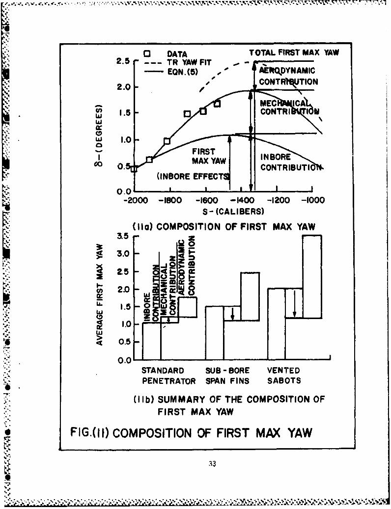
11 Composition of First Max Yaw ...................................... 33
a. Composition of First Max Yaw .................................. 33
b. Summary of the Composition of First Max Yaw ................... 33
4 5
LIST OF ILLUSTRATIONS (continued)
12A2
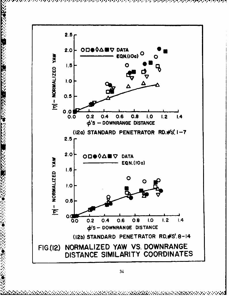
12 Normalized Yaw vs. Downrange Distance Similarity Coordinates .... 34
a. Standard Penetrator Round Numbers 1-7 ......................... 34
b. Standard Penetrator Round Numbers 8-14 ........................ 34
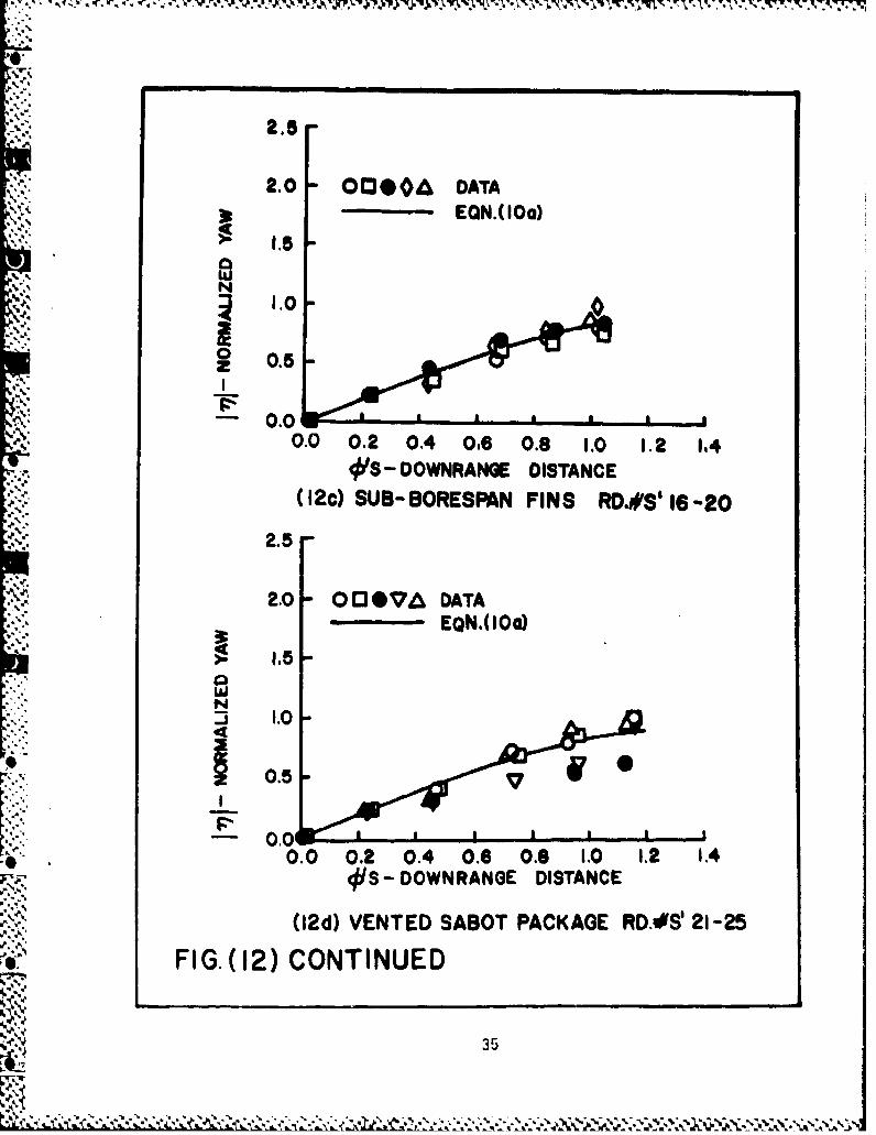
c. Sub-Bore Span Fins Round Numbers 16-20 ........................ 35
d. Vented Sabot Package Round Numbers 21-25 ......... ....... 35
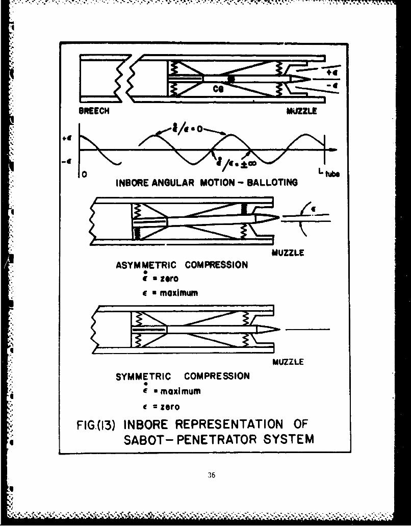
13 Inbore Representation of Sabot-Penetrator System .................. 36
14 Correlation of the Discard Disturbance to the Initial Conditions.. 37
a. Definition of the Discard Disturbance - an .................... 37
b. Discard Disturbance vs. Initial Angular Rate to Angle Ratio... 37
15 Comparison of the Present Data to Previous Data ................... 38
16 Comparison of the Discard Disturbance Correlations ................ 38
17 Discard Disturbances in the Alpha and Beta Planes ................. 39
a. Proof Slug .................................... 39
h. Standard Penetrator ......................................S.a.b.. 4039
c. Penetrator-Vented Sabot Package................. ........... 40
d. Standard Penetrator ...................... . ........ . ...... 40
e. Standard Penetrator ...................................... 41
f. Penetrator with Sub-Bore Span Fins ............................ 41
18 Angle of Attack vs. Angle of Sideslip ............................. 42
a. Standard Penetrator ...................................... ..... 42
h. Standard Penetrator ........................................... 42
19 Alpha and Beta Plane Discard Disturbance Correlation to theInitial Conditions .............................................. 43
a. Plane of Angle of Attack ..................................... 1 43
b. Plane of Sideslip ............................................. 43
6
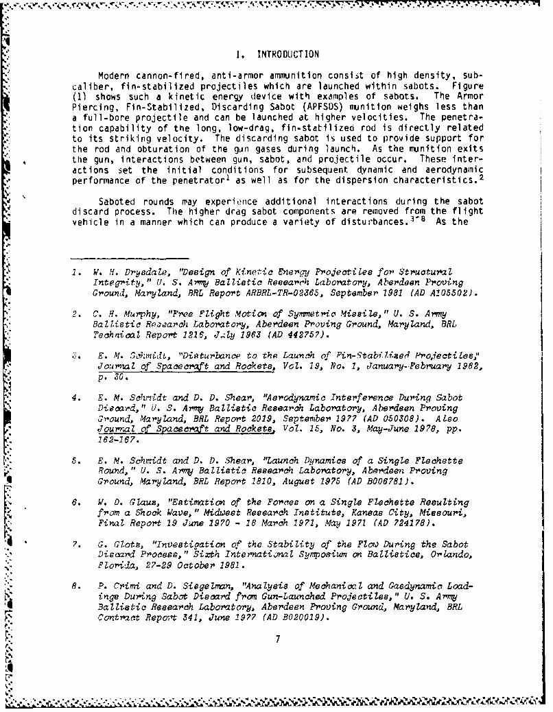
I. INTRODUCTION
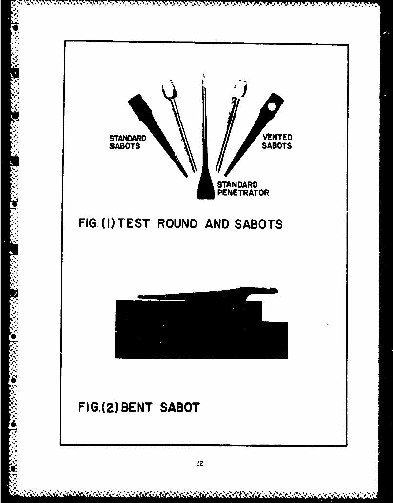
Modern cannon-fired, anti-armor ammunition consist of high density, sub-caliber, fin-stabilized projectiles which are launched within sabots. Figure(1) shows such a kinetic energy device with examples of sabots. The ArmorPiercing, Fin-Stabilized, Discarding Sabot (APFSDS) munition weighs less thana full-bore projectile and can be launched at higher velocities. The penetra-tion capability of the long, low-drag, fin-stadilized rod is directly relatedto its striking velocity. The discarding sabot is used to provide support forthe rod and obturation of the gun gases during launch. As the munition exitsthe gun, interactions between gun, sabot, and projectile occur. These inter-actions set the initial conditions for subsequent dynamic and aerodynamicperformance of the penetrator1 as well as for the dispersion characteristics. 2
"Saboted rounds may experience additional interactions during the sabot"discard process. The higher drag sabot components are removed from the flightvehicle in a manner which can produce a variety of disturbances.' 8 As the
2. W. H. Drysdale, "Design of Kinetic &nergy Projectiles for Structural
Integrity," U. S. Army Ballistic Research Laboratory, Aberdeen ProvingGround, Maryland, BRL Report ARBRL-TR-0O365, September 7981 (AD A105502).
2. C. H. Murphy, "Free Flight Motion of Symnetric Missile," U. S. ArmyBallistic Reaearch Laboratory, Aberdeen Proving Ground, Maryland, BRLTechnical Report 1216, Jaly 1963 (AD 442757)..E. M. Szmn•t, "Disturbance to the Launch of Fin-1tabilised Proiectites '
Jog yl of Spacecraft and Rockets, Vol. 19, No. 1, January-February 1982,p. 30.
4. E. M. ScTkmdt and D. D. Shear, "Aerodynamic Interference During SabotDiscard," U. S. Army Ballistic Research Laboratory, Aberdeen ProvingGround, Maryland, BRL Report 2019, September 19?? (AD 050308). AlsoSJoural of Spacecraft and Rockets, Vol. 15, No. 3, May-June 1978, pp.
162-167.
V�5. E. M. Schrnidt and D. D. Shear, "Launch D~ynamics of a Single FlechetteRound, " U. S. Arny Ballistic Research Laboratory, Aberdeen Proving
114 Ground, Maryland, BRL Report 1810, August 19?5 (AD B006?81).
6. W. D. Glauz, "Estimation of the Forces on a Single Flechette Resultingfrom a Shock Wave," Midwest Research Institute, Kansas City, Missouri,
r• Final Report 19 June 1970 - 18 March 1971, May 197.1 (AD 724178).
- 7. G. Clotz, "Investigation of the Stability of the Flow During the SabotDiscard Process," Sixth Internationawl Symposium on Ballistics, Orlando,
N, Florida, 27-29 October 1981.
8. P. Crimi and D. Siegelnan, "Analysis of Mechanixit and Gaedynamic Load-ings During Sabot Discard from Gun-Launched Projectiles," U. S. ArmyBallistic Research Laboratory, Aberdeen Proving Ground, Maryland, BRLContract Repo;'t 341, June 1977 (AD B020019).
'L7
V. -,'.' .' -. *. .*..- * * . .Q U
* . .. * ,* -.•.-T
shot e(i:erges from the gun tube, elastic decompression together with the resid"ual inertia of the sabot components start the discard sequence. Dynamic andaerodynamic loads on the sabot parts force them away from the prtjectile. Anyexisting geometric asymmetries in sabot components may cause a momentumexchanqe between the components and the long rod flight vehicle. As separationproceeds, air flow is established between the sabot parts and the projectile;?
stronq aerodynamic interactions occur and become the dominant source of the"discard disturbance. Schmidt 3 has observed that the two dominant discard-mechanisnis are mechanical contact and aerodynamic interaction. Flow fieldasymmetries have their primary effect on the projectile fins where skewedshock patterns have been observed by Schmidt and Shear." Wind tunnel data forthe pressures on symmetric and asymmetric sabot configurations have beenobtained by Schmidt and Plostins. 9 ' 0 Mechanical impacts have been observedby Schmidt et. al. 1 1 for the case of a spin-stabilized penetrator.
The initial dynamics of the penetrator are established during the launchprocess; therefore, it is important to size and determine thq contributions of,,arious phases of the launch cycle to the flight dynamics of the projectile.This retiort presents the results of one part of a test program on an APFSDSprojectile. The program was to study launch problems and prooose methods forthe mitiqation of launch disturbances. Only the sabot discard and discardeffects on other portions of the launch cycle are discussed here. An analysisof the perturbations to tne projectile angular motion due to inbore, mechani.cal, and aerodynamic interactions during launch are presented.
The comprehensive test proqram was a joint effort by the Interior Ballis-Stics Division (IBD) and the Launch and Flight Division (LFD) of the BallisticResearch Laboratorv (BRL). IBD was responsible for determining the inborebehavior of the rounds using doppler radar. 1 2 The LFD was responsible formeisurement of the aerodynamic performance of the penetrator and the sabot
'.). E. M. Schmidt, "Wind Tunne I Measurements of Sabot Discard Aerodvynamioe,""Y. S. ArmT Ballistic Research Laboratory, Aberdeen Proving Ground,Maryland, RRL Technical Report ARBRL-TR-02246, July 1980 (AD 088900).
19. PF. M. M.Schmidt and P. PZosatns, "Aerodynamics of Aoynmmetr-'c Sabot"1)io cad, " U. S. Army Ballistic Research Laboratory, Aberdeen Proving-',ound, maryland, BRL Report ARBRL-MR-03281, June 1983 (AD 130011).
. 11. F. Al. Schmidt, B. P. Bumas, and G. Samos, "Replica ModeZling of the !.aunt-hand Plight Dynam..cs of Projectiles,e" U. S. Arrmj Ballistic RiesearchLaboratory, Aberdeen Proving (,'ound, Mary land, BRL Technical ReportARRHL-TR-02104, September 1978 (AD A063521).
12. J. N. Waibert, "Analysis of the in Bore Motion of Several T ypes of*. Projoctiles," U. S. Army Ballistic Research Laboratory, Aberdeen Proving
Ground, Maryland, BRL Memorandum Report ARBRL-MR-03293, July 1983 (ADBO76398L).
, - 8
9-"
• '' : '-."?.... •. ...,ir...•.-''. r* r --. .'. -V'.- 'i- ", % N% W:b-..' •-. ---.-.. _, -2 • ,.,' - ,,-• J , Y , •
discard process. The test program was conducted at the Transonic Range tacil-ity' 3 ''• of the BRL.
II. TEST PRELIMINARIES AND TEST MATR;X
It was desired to test a projectile with improved flight and terminalperformance. The design improvements consisted of a lengthened penetratorbody with increased sabot load-bearing surface and a reduction of fin span to"decrease aerodynamic drag. The standard penetrator, Figure (1), is equippedwith bore-riding fins to provide inbore stability. The drag coefficient ofthe improved model was less than the standard projectile but at the expense ofinbore stability. As d result of these changes, the dispersion of the imurovedprojectile was greater than that of the standard projectile.
The long sabot also showed signs of permanent deformation, Figure (2).The aerodynamic liftoff characteristics of the sabots tested caused sabot taildeformation. Large initial sabot petal rotation produced significant loads at
the sabot tails which were the pivot points of the rotation. It was necessaryto change the initial lift and moment coefficients of the sabot components inan attempt to alleviate the effects of this mechanical interaction. The sabotlift was reduced on five test rounds by removing lift area through a ventingprocedure. Figure (1) shows a vented sabot petal. A first estimate of theeffect of venting the sabot was computed using the AVCO Sabot DiscardCode. 8'15 17 Both vented and non-vented cases were run. The code consists ofa dynamics package with a six-degree-of-freedom model for the sabot petals anda three-degree-of-freedom angular model for the penetrator, as well as asabot-penetrator interaction package and an aerodynamic interaction package.The aerodynamic package is based on shock expansion theory.
13. W. F. Braun, "Fiducial Systems for Free Flight Spark Ranges," U. S. ArmyBallistic Research Laboratory, Aberdeen Proving Ground, Maryland, BRLMemorandum Report BRLMR 2009, September 1969 (AD 860693).
14. 0. H. Murphy, "Data Reduction for Free Flight Spark Rangee," U. S. ArmyBaZlistic Research Laboratory, Aberdeen Proving Ground, Maryland, BRLReport BRLR 900, February 19h4 (AD 35833).
25. P. Crimi and D. Siege ban, 'Projectile/Sabot Discard Aerodynamics," U. S.Ar•my Ballistic Research Laboratory, Aberdeen Proving Ground, Maryland,BAL Contract Report ARBRL-CR-410, December 1979 (AD 080538).
16. D. Siegleman and J. Wang, "Sabot Des ign Optimization, " U. S. ArmyBal'istic Research Laboratory, Aberdeen Proving Ground, Maryland, RRLContract Report ARBRL-CR-450, March 1981 (AD 100264).
17. D. Siege lan, J. Wang, and P. Crimi, "Computation of Sabot Discard, "U. S.Army Ballistic,- Research Laboratory, Aberdeen Proving Ground, Maryland,ARL Contract Report ARBRL-CR-505, February 1983 (AD B0715792).
9
•'7' -' "• -.. ' " ' " -' '- " . L'• V '. .. . . . -. ' w - -. :-' -. ; '.. ', > ..- W ,
"The measure of the severity of discard interaction is the Inte gratedangular impulse experienced by the penetrator during the discard sequence.
**Total Angular Discard Impulse I Im + Ia (1)
t t
"Im f Mmdt l ft Ma dt (2)0 0
where Ma is the total moment due to aerodynamic loads and Mm is the totalmoment due to mechanical loads. The restults of running the code showed that a50% vent (hased on area) in the sabot cup would reduce the mechanical impulse,Sli, by 57,. The mechanical interaction model in the code 8 provides a linearvariation of impulse with vent area. The limit to the size of the vent holeis, however, set by considerations of mechanical strength of the sabot petal.Thus, the sabots of five standard rounds were modified to provide vent holeswhich red(ced the front cup lift area by 21%. The introduction of vent holes, . to the sabot cups had the unfavorable consequence of increasing the time dur-inq which discard interactions occur. Even though the sahot tail mechanicalinteraction force might be reduced through venting, the increased discard timecould result in greater total interaction impulses. It was decided to test,, the tive rounds with vented sabots to determine the effect of lift reductionorl discard behavior.
A total of twenty-seven rounds were tested. Two were proof slugs, firedto calibrate the test equipment. Proof slugs mimic the sahot-penetrator shotinbore. They are monolithic, without moving parts. Fifteen standard rounds"with horespan fins and non-vented sabots were fired to provide a baseline forcom'mparison with the experimental models. Two experimental groups of fiverounds each were fired to determine the effects of sub-borespan fins and theeffects of vented sabot petals. The first five rounds used the lengthenedpenetrator with sub-borespan fins and the standard sabot. The second fiverounds used the lengthened penetrator with borespan fins and the ventedsabot. Twelve of the above penetrators were modified by establishing a radar-reflective flat surface at the nose for doppler radar measurements. The proofslugs have full frontal flat surfaces.
One caliber is defined as the diameter of the body of the penetrator.The standard test projectile had 3.91 caliber borespan fins and a length-to-diameter ratio of 23. The sub-borespan fins had the same surface area as the"borespan fins but were 3.31 calibers in diameter. The ratio of moments ofinertia Ix/Ily was 4.46 x 10o03 and the transverse radius of gyration was 5.91calibers and the axial radius of gyration was .395 calibers. The penetratorwith sub-borespan fins had practically the same inertial properties.
.Ill. DATA ACQUISITION AND INSTRUMENTATION
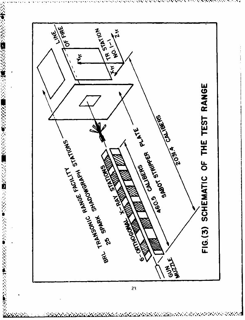
A schematic of the experimental test setup is shown in Figure (3). The* discard sequence data were obtained from six orthogonal x-ray stations whichcovered the first 460.5 calibers of penetrator travel. Free flight data ofthe penetrator motion were collected in the Transonic Range facility. The
10
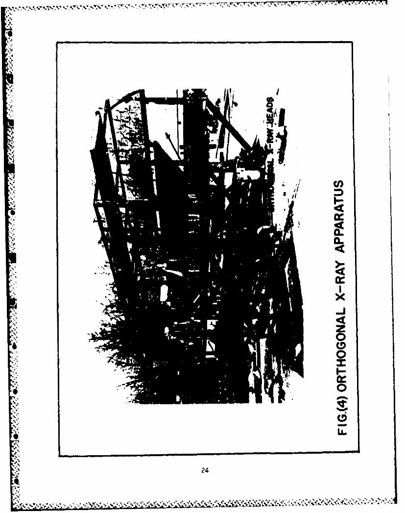
instrumented Transonic Range consists of an orthogonal array of 25 sparkstations covering a 207 metre length of the flight path. The first station,number 1-1, was considered the zero point of the test. The muzzle of the gunwas located 2031.4 calibers uprange from station 1-1. The x-ray apparatus,Figure (4), was calibrated with a fiducial cable strung through the six sta-tions along the line of fire. Three fiducial beads are located at the center-line intersection of the x-ray heads as shown in Figure (Sa). The center beadwds surveyed into the Transonic Range coordinate system. The outer two beadsprovide a measure of image magnification on the x-ray plate. In the rangecoordinate system, the z axis Is along the line of fire, the x axis is posi-tive to the left looking downrange. and the y axis is in the recoil plane ofthe gun to fonri an orthogonal triad. The locations of the six center beadsalong the line of fire were surveyed:
Station Number Location
I z - -2020.5 cal 3a2 z - -1924.5 cal (3b3 z = -1826.4 cal (3c4 z - -1721.0 cal (3d)
5 z =-1639.8 cal (3e)6 z - -1560.0 cal 31
A low level x-ray photograph of the cable was taken before each firing.The cable was then removed from the line of fire and a second exposure of thufilm recorded the penetrator and sabot motion during the test. Thus, thedouble exposure contains a record of the fiducial cable, the penetrator, andthe sabot. Figure (5) is an example of the type of x-ray data obtained.
The x-ray heads used for the test were two 180 KV units at stations oneand two and eight 150 KV units for stations three thru six of the x-ray set-up. Digital counters, accurate to 0.1 microsecond, were used to obtain timeintervals between stations. A photodiode which detected the muzzle flash wasused to trigger the x-ray delay units and digital counters.
IV. DATA REDUCTION AND TEST RESULTS
lhe data obtained from the tests were orthogonal x-ray photographs andtime measurements. The x-ray photographs show the fiducial cable, the fidu-cial beads, and the model and sabot components. Since x-rays are conicalsources, objects close to the x-ray heads appear larger on the photographsthan objects farther from the heads. For these tests, however, only thepenetrator performance was measured and the deviation of the penetrator tra-
* * jectory from the line of fire was sufficiently small to allow magnificationerrors to be ignored. A detailed discussion of errors in range x-rayphotog-raphyisgiven in Reference 5, Appendix A.
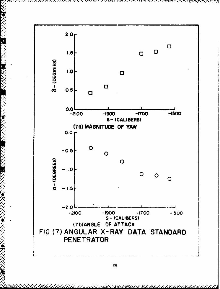
The orthogonal x-ray photographs are measured to provide the location ofthe center of gravity of the model as a function of downrange position and theangular orientation of the model with respect to the velocity vector. Theangle of attack, a, and the angle of sideslip, $,are thus determined. These
11
mp.
, , , * A . _ . d .
angles are depicted in Figure (6). The angle, 6, is defined as the magnitudeof the local angle of attack, or the angle between the penetrator axis ofsymmetry and the velocity vector. For small angles, 6 is given by
S--' 6 (=2 + +2)1/2 (4)
"F"igures (7a-c) show typical angular behavior for a standard penetrator. For apenetrator in free flight, the dominant applied torque is the aerodynamicstatic moment. During sabot discard, an additional applied torque due to the"discard mechanism must be considered. Most discard loads are applied at ornear the penetrator fins. Hence, a small force may be magnified by a longmoment arm to produce a substantial torque. It is hoped that the analysis ofthe photgraphic data taken in these tests will produce a measure of theeffects of the discard torque loadings.
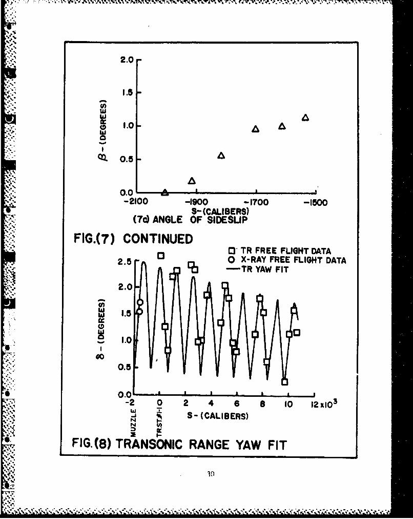
!n addition to the orthogonal x-ray data taken during the tests, free"flight range data relevant to the aerodynamic behavior of the rounds wereobtained in the Transonic Range. The important aerodynamic coefficientsmeasured were CD the drag coefficient, Cx 0, the lift curve slope, and Cm., the
static moment coefficient. Thp results of the standard range reduction pro-cedure2 also produce a history of the yawing motion within the range. Atypical yawing history based on a fit of the reduced range data for a standardpenetrator is shown in Figure (8). The fitted curve between the muzzle andstation 1-1 was the result of extrapolation. From the fitted data, values ofthe first maximum yaw, 6max, the initial angular rate, 6, and the initial
max' 0yaw, 6 0, can be obtained. These values are a direct measure of the total
launch disturbance experienced by the penetrator. The customary assumptionsare that the launch disturbance occurs at the muzzle of the gun and isentirely due to inbore effects. For the case of saboted projectiles,additional disturbances must be accounted for in the transition region betweenmuzzle and free flight.
The initial angular rates at the nuzzle are computed by taking first dif-ferences of the data at the first two x-ray stations. To obtain the yawingmotion from the first differences, certain simplifying assumptions are made:(1) at the muzzle the round is not rolling (smooth bore gun); (2) damping isnegligible (less than one cycle of yaw is observed); and (3) gravity need notbe considered (short segment of trajectory). The angular motion, then, is
-q?
4'(o / ) sin(O'S) + Z cos(€'S) (5)
0
where, Z is the complex angle of yaw, Z 0 is the complex initial angle of yaw,
C is the complex initial angular rate, S is the distance along the trajec-:0tory, and 0' is the yaw frequency. Prime, ', denotes differentiation withrespect to distance. The magnitude of yaw, 6, is identically the magnitude of
o the complex angle of yaw, C. Thus, the yaw frequency is related to the staticmoment coefficient by:
12':.s
= E(pAd3 /2[y) Cm0 ) 1" 2 . (6)
Typically, the yaw frequency of the test penetrators considered in the testis, a0 2.406 x 10-05 (rad/cal). Equation (5) is used to predict the yawbehavior based on measured initial rates and angles.
A. First Magnitude of Yaw Effects
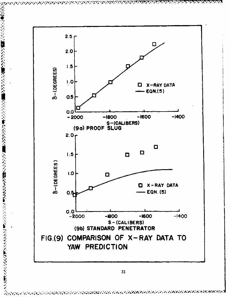
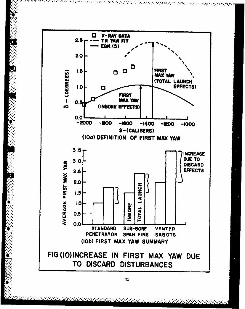
Total angle of attack versus distance downrange for a proof slug and astandard penetrator are shown in Figures (9a) and (9b). The results of usingequation (5) to predict the yaw magnitude are also plotted. The data ofFigure (9a) for the proof slug agree well with the behavior predicted by equa-tion (5) since the slug was a full bore round with no discarding parts.Evidently muzzle blast effects can be ignored. The penetrator data shown inFigure (9b), however, diverge from the prediction of equation (5) after z =-1924.5 calibers. The penetrator data contain all the effects of the sabotdiscard disturbance and the figure shows the importance of taking these dis-turbances into account. From the Transonic Range round reduction, a firstmaximum yaw can be computed. For the penetrator, this yawing behavior isshown in Figure (10a) (dashed curve) and is compared to the prediction ofequation (5) based on the muzzles rates. Also plotted for comparison are thedata from the x-ray stations. The increase in first maximum yaw due to launchdisturbances is clearly evident. The average first maximum yaws for the threedifferent penetrator/sabot configurations are compared to the inbore predic-Lior. in the bar chart presentation of Figure (lOb). The standard penetrator/sahh,.- configuration showed the least inbore as well as discard effects.There is a progressive increase in both inbore and discard effects with thesub-borespan finned configuration and the penetratori-ented sabot assembly.The percentage of first maximum yaw due to discard disturbances is about 41%for each of the three types of test rounds.
B. Mechanical Separation
The test results show that mechanical separation plays an important rolein the magnitude of observed initial yawing motion. Direct mechanical contactbetween sabot parts and the penetrator was maintained until the assemblyreached station two. (Figure (5a-b)). Between stations two and three, mechani-cal separation took place as seen in Figures (Sb-c). Beyond station three thediscard interaction was purely aerodynamic. The photographic evidence sug-gests that only a single mechanical interaction took place between stationstwo and three. Using the angular information at station two and first-orderdifferences between stations two and three to obtain rates, initial values forequation (5) were computed and a yaw behavior predicted. This new yaw behav-ior was analyzed to yield a first maximum yaw value which is due to both theangular momentum produced by mechanical interaction as well as the angularmomentum resident in the system at station two. Figure (11a) shows all threecontributions to the first maximum yaw: inbore, mechanical, and aerodynamic.
The penetrator was in free flight past station five as seen in Figures(5e-f). Figure (5e) shows the sabot petals sufficiently far removed from thepenetrator to provide any intersecting shocks with the penetrator tail.Figure (5f) shows that the sabot shocks were behind the penetrator. Data from
13
stations five and six were included in the range reduction. Although therange reduction did not predict the correct location of the x-ray free flightdata, Figure (11a), the angular rate of the x-ray data at stations five andsix were reasonably well predicted. Beyond station three, strong shock inter-actions between sabot petals and the penetrator provided the final discarddisturbances. The momentum exchange due to aerodynamic discard effectsbrought the angular mumentum of the Denetrator to a level compatible with thatindicated by the first maximum yaw extrapolation from the range reduction.The bar chart of Figure (11b) illustrates the contribution of each of theeffects, inbore, mechanical, and aerodynamic, to the average first maximum yawfor each penetrator/sabot type. The Figure shows that the mechanical separa-tion effects were "favorable" for the penetrator with sub-borespan fins andthe penetrator with the vented sabot petals but were larger in magnitude thanfor the standard penetrator. The aerodynamic interaction was least for the
Sstandard penetrator and greatest for the penetrator/vented-sabot configura-tion. The adverse aerodynamic effect for the penetrator/vented-sabot case wasdue to the longer discard interaction times of the vented sabots.
"V. ANALYSIS
The analysis of the preceding section gives an overall view of the inter-*i action between discard disturbances and the penetrator and shows how the
"interaction changes the initial angular momentum to the free flight value.The penetrator with vented sabot petals has the greater total first maximumyaw despite the "favorable" mechanical interaction. The term "favorable" ismeant to indicate a reduction in first maximum yaw. It should be made clearthat any discard interaction which causes the penetrator to deviate from itsoriginal yaw behavior is undesirable.
A more detailed investigation of the discard sequence can be made if abaseline for comparison is available. Inasmuch as there is no control overinbore effects, we select the yaw predicted .,y the measured angular rates atthe muzzle as the baseline. This baseline, then, is the curve in Figure (11a)labeled "inbore effects." Each test round fired had different initial condi-tions at the muzzle. Therefore, in order to compare the results from differ-ent rounds, it is necessary to normalize the results in such a way that theyare either in a common reference frame or are presented relative to the base-
v• line. Equation (5) can be rewritten in the following form:
n = [Z - Zo cos('S)]/(Z'o/') = sin(4'S). (7)
* Equation (5) can be decomposed into real and imaginary parts and is normalizedjust as was equation (7):
=3 -3 cos(.OS)J/(;/r) sin(O's). (8a)
n [W -0 cos(s'S)]/(O;/') = sin(O'Sý. (8b)
o..
4." 144---
,. . . .•. . % . * . . . ' - - - -
The magnitude of Equation (7) is:
""jm = IEZ - Zo cos(.OS)l/(Zo/f')l Isin(O'S)t. (9)
We will refer to Inj as the normalized yaw. Thus, the equation describing theyawing motion of a round in free flight has been recast in normalized form sothat all rounds in free flight are described by a single curve independent oflaunch conditions. This procedure is akin to writing boundary layer equationsin similarity coordinates. The pertinent similarity variables here are In'and 'S. Thus, the free flight yaw behavior is scaled in amplitude, 0 f ii- 1, and in frequency, 0 e +'S 4 2w. The normalization has removed the inboreor initial effects and the free flight motion of all penetrators is describedby:
hIn = Isin(O°S)l. (10a)
The test data can then be used to evaluate:
0 0jrl = Iiz-zo cos(2+S)]/(-,/*iIl. (lOb)
I = - ýo cos(OS)] 2 + "o cOs(,S)]211 / 2 /((02 + ;2)/,2h1/2. (Moc)
Any d&fference between the test data and Equation (10e) is a measure of theC. effects. of the discard loadings only.
A plot of Inl versus *'S is given in Figures (12a-b) for the standardA. penetrator, in Figure (12c) for the penetrator with the sub-borespan fins, and
"in Figure (12d) for the penetrator/vented sabot configuration. The standardpenetrator is seen to have the greatest discard disturbances. The penetratorwith the sub-borespan fins seems to have the least discard disturbances. Both
*• the penetrator with sub-borespan fins and the penetrator/vented sabot showsignificantly less discard disturbances than the standard penetrator. Thisstatement appears to contradict the statements made about Figure (11b). Inthe normalized system, the discard disturbances are measured relative to the"inbore effects and consequently a strong discard disturbance does not necessar-ily result in poor overall performance.
Figures (12a-b) include a significant amount of data for the standard
penetrator. Within certain tolerances, one standard penetrator/sabot round isidentical to the next and all rounds were fired from the same gun. Neverthe-
"At, less, the discard disturbances range from weak to strong. If the discardA disturbances were symmetric, one would not expect the firing data to deviate
from the predictions of Equation (lOa). The data, however, do differ, and,"the greater the difference, the more asymmetric the discard disturbance. The
15
_.5C.

,.. * . . . - , . . . . . . . . . .
asymmetry Is found in the initial conditions at the muzzle of the gun. Whilein the gun tube, the round experiences a periodic motion known as InboreballoLing. A planar description of balloting is shown in Figure (13). Thepenetrator/sabot shot center of gravity moves toward and away from the axis of
* the tube and the shot yaws about its center of gravity. The sabot componentsv.-. which constrain the penetrator to move along the tube axis can be modeled by
two stiff springs. As the shot ballots in the tube, the sabots elasticallyexpand and compress. At muzzle exit, the sabots can be elastically stressedbetween two limiting states. Either one sabot component is highly stressedand the other is relaxed or both sabot components are equally stressed.
If the inbore behavior is assumed periodic, and given by a cosine law, wecan write:
e = A cos(wt + 00) (11a)
where e is the angle the penetrator makes with the tube axis. The rate atwhich the penetrator/sabot shot ballots is:
•..• •=--,A sin(wt + ,o) (11b)0~
The angular orientation of the package inbore is uniquely described by c and
Z. The balloting amplitude can be eliminated by taking the ratio of Equations(11a) and (lib):
a/c = -w tan(wt + 0 ) (llc)
"which describes the system in terms of the balloting frequency, w, and an"initial condition, *o" For a given system, the balloting frequency, w, is afunction of the system geometry. The initial condition is indeterminate andvaries with shot start at the breech of the gun. The length of time, t, the
I shot is in the gun is a function of tube length and shot velocity. For agiven tube and fixed charge, t does not vary significantly from one shot tothe next. Thus, 00 is responsible for the variations in a/c and this ratio is"a measure of the state of stress of the sabot components.
* At the peak of the balloting motion, Z goes to zero and, consequently,
-/; goes to zero. At this point in the motion, one sabot component is morehighly stressed than the other. Conversely, the point of equal sabot stressesoccurs at the maximum angular rate with the balloting angie equal to zero,that is, as a/c goes to infinity. The elastic decompression of sabot compo-
". nents starts the discard sequence and is the mechanism by which asymmetry inthe gun tube is transferred to the discard sequence. If a/c is a measure of
16
. -
.~- . ~%~,.*.~ - - . . * • .r - .~-- .- -r ~frr .. . .. b. * - • •.-.
S;..
asymmetry at tube exit, it should correlate with the severity of the discardinteraction. The x-ray data provide the muzzle angular rates and angles. Letus describe the severity of the discard by the parameter an, the magnitude ofthe difference of the data from the behavior predicted by Equation (10a),Figure (12). Figure (14b) is a plot of lAnl versus V/6 , the absolute value
". of s/c. Only rounds with data at station six are included in the plot. Allthe rounds with large discard disturbances are grouped near zero. These
"I rounds exit the tube with one or more of the sabot petals highly stressed inan asymmetric fashion. Of greater significance, however, is that there existsa region beyond which the discard disturbances are a minimum. Note that thenonstandard penetrator/sabot packages were launched with 6'/6 on the border-
0 0line or beyond the point where the discard disturbances approach a minimumvalue.
The quantity lAni is an accurate measure of the launch disturbance onlyif evaluated in the neighborhood of first maximum yaw where it directlyrelates to the total work done on the penetrator. Evaludted away from firstmaximum yaw, Ian] can be related only to that part of the total work donebefore first maximum yaw. Thus far, Inl is only a measure of the differenceof the data from the yaw behavior predicted by the initial conditions at themuzzle. Since the discard not only alters the level but also displaces the
* position of first maximum yaw, it is not clear how close the data are to theA. first maximum yaw. The correlation of Figure (14b) may be fortuitous because
"of this consideration. The paucity of data is an additional problem in evalu-ating the correlation. In future tests, data must be obtained at first maxi-
,. mum yaw. At values of 6'/a where large discard disturbances were evident,
data also existed for rounds with small disturbances. Thus, a low value of'5'/6 is a necessary but not sufficient condition for large discard disturban-
ces. There are other conditions which comprise a sufficient set and what they"consist of is a topic for further research.
Schmidt and Shear 4 have obtained penetrator yaw data for a 60mm sabot-penetrator combination. The sabot design is similar to that for the presenttest rounds with the exception that the front lifting surface does not have
the extended cup. The rounds of Reference 4 were fired from a rifled tubeJ.. while the rounds of this report were fired from a smooth bore tube. The 60mm
round has an initial roll rate of 110 rev/sec and uses centrifugal accelera-tion together with aerodynamic loads to throw off the sabot components. The
*. data from Reference 4 can be analyzed in the same way as the data from thesmooth bore firings. The normalized yaw, n, is redefined to include theeffects of roll. The following yaw equation applies for the rolling case:
•;• = [Eo/(iC - *))][eliS_- ei1'2S]
+ [tol(si -*)][B1ei2-S -Ae
The magnitude of the normalized yaw is defined as:
"17
.1o• • • • • • - • , "-. "• ".,W f " ,' " " ,"' • ' . ' - • • V•, , . - . . w . .- " 'i-'' •- •1%
'0S00llml 1Z -" o Colet 2 1 2I, [ ( ) e - ei'OSI. (19b)
The fast and slow frequencies, 01 and 2, may be evaluated from:
= (1/2)[iP ± (4 M- p2)1/2] (13a)
M [pAd 3 /(21y)] Cm . (13b)
P = (pd/V) (Ix/Iy) . (13c)
The downrange similarity variable in this coordinate system is now (01 - )S.The data are evaluated using the first equality in Equation (12b) and the pre-
"-.. diction is computed using the second equality in Equation (12b). Figure (15)shows a comparison of the data from the standard penetrator of this reportwith the data from Reference 4. The effects of the discard disturbances arequite similar. In both tests, the data differ from the similarity prediction.Just as for the standard round of this report, Figure (12a), a variety of dis-card disturbances are evident for the data of Reference 4. Let us define nAnd"as before, and correlate the Reference 4 data with initial V/6 . Figure 16
0 0shows that the data of Schmidt and Shear appear to have the same type of rela-tionship to initial conditions as the present case. The results are plottedin the coordinate system of Equations (12) so that both sets of data areproperly scaled relative to each other. Only five data points are availablefrom Reference 4 and hard conclusions cannot be made. The proper trend, how-ever, is indicated.
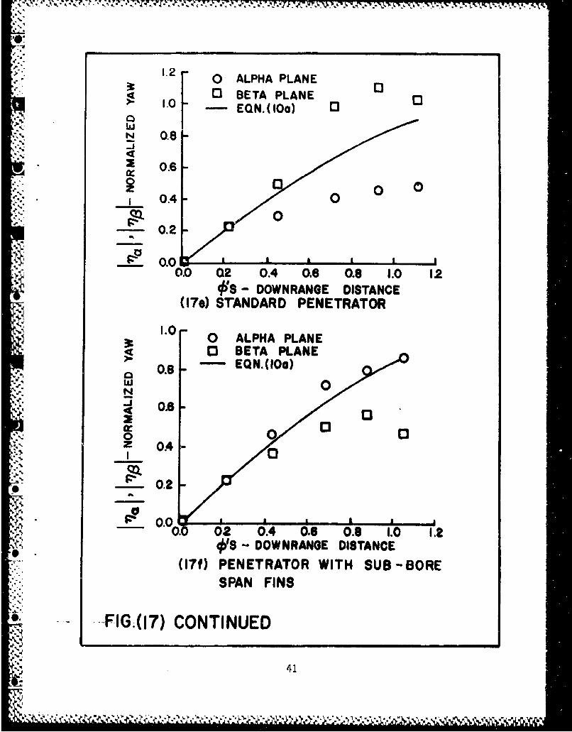
The analysis thus far has considered the effects of the discard processon the total yaw. If the discard disturbances are not a function of the yaw-ing motion of the penetrator then theperturbations to the total yaw are a goodmeasure of the discard effects. However, should the yawing motion of the pene-trator and the discard loads be coupled, thena similar analysis can be used onthe components of yaw. It is possible to construct the effects of discard onthe components of yaw, that is on the pitching and yawing motions considered"separately. The components of yaw, t.' angle of attack, and the angle of side-0 slip are not necessarily similar in amplitude and the discard disturbancesare not necessarily in either plane. Equations (8) have already been devel-"oped to provide expressions for normalized yaw in both the pitch and yawplanes. Let us begin by considering the proof slug. The proof slug has nodiscarding sabot, hence no discard disturbance, and its components of yaw, n.and rii, should correlate with the predictions of Equations (8). Figure (17a)shows the results of a comparison of In.l and Inj with the magnitude of the
18
.1m
* *- . . .. S . -** * . - ** * -.
second equality of Equations (8) and it is seen that the data agrees with theprediction and behaves the same for either function.
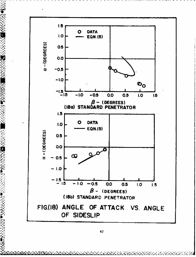
For the sabot/penetrator packages, a variety of disturbances are possi-ble. Figure (17b) gives an example of a discard disturbance acting in the aplane only. Figure (17c) shows a small disturbance in either plane. Figure(17d) illustrates equal discard disturbances in both a and p planes. InFigure (17e) we see an "unfavorable" disturbance in the a plane and a "favor-able" disturbance in the a plane. Finally, in Figure (17f), we see almost nodiscard disturbance in the a plane and a substantial disturbance in the Bplane. Figure (18a) shows the result of plotting the yaw predictive equation(5) as well as the standard penetrator data in the a - 8 plane. The yaw pre-diction is the usual ellipse while the data seem to show planar motion. P nthe other hand, Figure (18b) shows a planar prediction while the data exhibitnon-planar behavior due to the discard process.
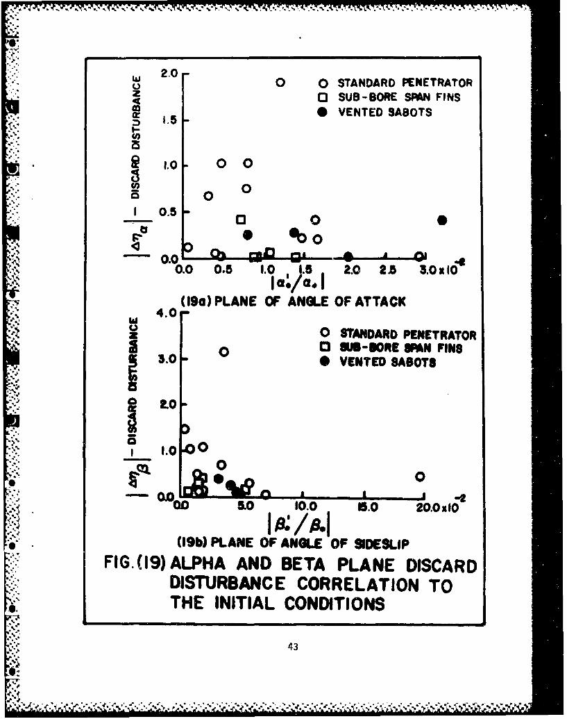
For a non-rolling projectile, the pitch and yaw equations are uncoupled.If the discard phenomenon is not a furction of the angular motion of the pene-trator, then the disturbances can be resolved into a and B components and theequations remain uncoupled. If we assume this to be the case, we can definelAn1a and JAnBJ in a fashion similar to JAnl, Figure (17d). The correlations
for the discard disturbances in the a and 8 planes are given in Figures (19a-b). These correlations are not as pronounced as the correlation for the totaldisturbance, 1A01. This leads to the con'lusion that for this round the dis-card disturbances may be weakly coupled to the yaw behavior of the penetrator.Nevertheless, the evidence supports *he contention that the largest discarddisturbances occur for low values of ao/ao or 0'/6o.
VI. SUMMARY
A series of firing tests of standard penetrators, penetrators with sub-borespan fins, and penetrators with vented sabot petals was conducted to pro-vide data relevant to the sabot discard process. Analysis of the test resultsshows that it is possible to quantify the magnitude of the inbore, mechanical,
and aerodynamic contributions to the total discard disturL.,nce. Gross effectsof the discard disturbances can be readily determined from the firing results,as seen in Figure (11b). A full-bore round experiences only inbore effectswhile sub-bore penetrator/sabot rounds experience severe discard disturbances.The discard disturbances lead to increases in first maximum yaw of about 41%for the standard penetrator. The vented sabot/penetrator packages and thesub-borespan fin penetrators also have a net increase in first maximum yaw ofabout 41%, but the discard effects contributed more strongly to the firstmaximum yaw increase.
Penetrator/vented sabot packages showed increased inbore effects over thestandard penetrator/sabot configurations. Inbore, the standard penetrator, isthe most stable since it has a front borerider as well as a rear borerider,the fin assembly. The penetrators with sub-borespan fins lose the rear bore-rider stability and an increase in inbore effects is noticed. If the inborecontribution of the standard penetrator is used as a baseline for comparison,then the loss of the rear borerider gives about 50% increased inbore contribu-tion. The vented sabot/penetrator packages produced about 100% increase in
19
• ;'-'..r,. r. cr,''. r . . ;r.•.. rr, . ry*. . ..- - y., .. ,.-: ... .. . - •,, ..-...-.• . r: . r• -X,.-.. . . .¶ •• •, . . ,• .
the inbore contribution. Venting the sabots may eliminate initial aerodynamiclift but the structural response of the front boreriding system is alsochanged. Since the penetrators with vented sabots also had boreridirg fins,it is clear that the structural design of the front boreriding system is crit-ical to the iWbore behavior. Indeed, the front boreriding design seems muchmore important than the rear boreriding fins. The front boreriding systemcould be structurally stiffened to upgrade inbore performance. The resultshould be levels of first maximum yaw comparable to those of the standardpenetrator. A series of such experiments is recommended since the payoffwould be improved terminal penetrator performance with higher accuracy.
The purpose of the vented sabot/penetrator tests was to relieve themechanical interaction between penetrator and sabot. Although the mechanicalinteraction changed from "unfavorable" to "favorable." it did not reduce themagnitude of the interaction, but rather increased it. A change in the firstmaximum yaw is produced by an angular impulse which is an integrated quantity.The increase in discard time was enough to increase the magnitude of the
* impulse even though the applied moment may have actually decreased. Theeffect of increased discard time is also evident from the increased aerodynam-ic disturbance to the penetrators with the vented sabot package. The AVCOsaoot discard code 8 predicted a redu,'tion in the level of the mechanicalimpulse for the vented sabot/penetrator package. It is clear from the datathat this was not the case. The AVCO code computations were based on a sym-metric discard of the sabot components. A computation including the asymmet-ric effects on the discard is needed for a proper comparison. Such a computa-tion is presently being performed.
A simple model of the inbore behavior of sabot/penetrator combinationsallowed a correlation between the severity of the discard and the initial con-ditions at the muzzle. From these correlations, Figures (14b), (1ga-b), itcan be seen that sabot/penetrator combinations with small initial 6;/60 ratios
(related to an asymmetrically compressed state) are characterized by largediscard disturbances. There is a point beyond which the discard disturbancesappear to diminish to a constant level.
The aerodynamic dispersion of a full bore round is related to the angularrate at the muzzle. Improved performance of full bore rounds can be achievedby reducing the initial angular rates. For sabot/penetrator combinations,such a strategy could lead to increased discard disturbances, offsetting anygains achieved by reducing the initial angular rates. Thus, the optimallaunch point for APFSDS ammunition is at values of 6'/6o beyond the point
where discard disturbances manifest themselves (i.e. at a 6'/6 of 0.015 inFigure (14b) for the present case) and at the least possible angular rate for
a minimum inbore launch disturbance.
VII. CONCLUSIONS
1. The net increase in first max yaw associated with sabot discard distur-bances averages 41% for all APFSDS rounds tested.
20
-' ,, • . ; 1..••;; ,: .;-..-.. ; .'V- ''.C'*" ." '.-.'--' * * , - .,- • . • ' .• •, • •, • '• ' ,
2. The inbore contribution to first maximum yaw of a long rod penetrator maybe reduced by stiffening the front borerider.
3. The severity of the discard disturbances can be correlated to the initialconditions at the rmuzzle.
4. Sabot/penetrator combinations launched in an asymmetrically compressedstate are characterized by increased discard disturbances.
5. There is an initial angular rate to angle ratio beyond which the discard-0 disturbances asymptote to the constant level.-N
6. APFSDS ammunition should be launched at angular rate to angle ratios largeenough so that the discard disturbances do not manifest themselves and at
- angular rates producing the minimum inbore launch disturbance.
21
STANDARD VENTEDSABOTS SABOTS
STANDARDPENETRATOR
FIG. (I) TEST ROUND AND SABOTS
,4.-'
FIG.(2) BENT SABOTS.
e°.,
• 122
**h %*4 \** ? 4' ,4•..4: 2z -. ~**.
* 06 *1* .. % ý%'.
S;t
0.'
INO
CA LL
op 0,
S.I.
%.S.
SS~U
4,
4;
A2'
.4L
244
7%xN , - .0 =
CALIBRATION BEAD FIDUCIAL CABLE
MAGNIFICATION BEADS
(5a) MUZZLE EXIT
* 1 (5b) MECHANICAL INTERACTION
* ~FIG.(5) DISCARD SEQUENCE X-RAY DATA
i7k
(S)SABOT SEPARATION
(5d) AERODYNAMIC INTERFERENCE
FIG.(5) CONTINUED
I, j26
A* 'L% i*,, .'Ls' V -Ilk I- %.7 4- k
-4
(5f) FNEEIATION H PNTRTRFE
FIG.( CFLINUET
%,2
,-4
,(S) R FLIGHT --
'.:!
"' ~FIG.(5) CONTINUED
-4-
_ _i >
Iw~C6
CII L
4. IJ
CL I
LL0 C/)
ww-J w
0 zw 0-J 0
0z 0
z zwwCL~4.r
(0
022
20
01.5 -0
Co
1.0 oSI .O 0
00 0 0 .5 - C
0.0 p
-2100 -1900 -1700 -1500S- (CALIBERS)
(7a) MAGNITUDE OF YAW0.0
-0.5 00
0
S0 0o 0
o -1.5 -
-2.0 -" "-2100 -1900 -1700 -1500
S- (CALIBERS)
(7b)ANGLE OF ATTACK
FIG.(7) ANGULAR X-RAY DATA STANDARDPENETRATOR
29
N .. o1 , -,•.L,, ',' ,•% ,' •1J '" "'• .'•J = J ,''"• '"• " ,? ,,' .,p @ ,' " •
-~. ~2.0-
• oo
IL' 1.0 A
0.5
0.0-"-2100 -1900 -1700 -1500
8-(CALIBERS)(7c) ANGLE OF SIDESLIP
"FIG.(7) CONTINUED2.5 0 TR FREE FLIGHT DATA
2.5 0 X-RAY FREE FLIGHT DATA-TR YAW FIT
- 2.0
cn
w 1.5
1.0 03
0.5
0.0-2 0 2 4 6 8 10 12 xM0
S - (CALIBERS)
SFIG.(e) TR=ANSONIC RANGE YAW FIT
S.L
i, ','
r.p.. :
I.I
aD
2.5
2.0 -
Lii
.:1.0S0 X-RAY DATA- - EQN.(5)
S0.5
0.0- 2000 -1800 -1600 -1400
S-(CALIBERS)(90) PROOF SLUG
1.5 0 0
- 1.00
II
-2000 -So0 -1600 -1400"" S - (CALI BE RS)
I;' •(9b) STANDARD PENETRATOR
FIG.(9) COMPARISON OF X-RAY DATA TO
YAW PREDICTION
31
.'Ii '', ,"'''' "• • '''"•. .-" ,"' ' ""-" " . .- -' '•- : " ¢ ' 'i*-'; '"•'.• .•; '-•""•,•,' '-' •,•••''r " ° " ''-
0 X-RAY DATA2.5 ---- TR YAW FIT
-EON(S) - -
2.0 -
1.5 13 0FISMAXYA
.0.
-2000 - MOO -111O -1400 -1200 -10006- (CAUIBERS)
(10a) DEFINITION OF FIRST MAX YAW
3.5 INCREASE3.0 DUE TO
~3.O DISCARD2.5 EFFECTS
V ~ 2.0-
* 1.0-0wr _j4t 0 4
cc O.5 0 1
4 0.0 _A _ - .....
STANDARD SUB-BORE VENTEDPENETRATOR SFAN FINS SABOTS
(l0b) FIRST MAX YAW SUMMARY
FIG.(O) INCREASE IN FIRST MAX YAW DUETO DISCARD DISTURBANCES
32
0 DATA TOTAL FIRST MAX YAW
2.5 --- TR YAW FIT .-
"EQN.(5) - AEKODYNAMIC.- CONTR JTION
MEC ICANTOw
(INORE EFFCONTRIBU
IN%0.0 1-2000 -1800 -1600 -1400 -1200 -1000
S- (CALIBERS)
(la) COMPOSITION OF FIRST MAX YAW3.5 z
ZF
_ 4.oE•.,8rLa. 1.5
1.50 0w c
4. < 0.5
0.0 -STANDARD SUB -BORE VENTEDPENETRATOR SPAN FINS SABOTS
(lIb) SUMMARY OF THE COMPOSITION OF
FIRST MAX YAW
FIG.(II) COMPOSITION OF FIRST MAX YAW
33
2.5
2.0 - O0!,•U7 DATAEQN.(IOa) 0
1.5- 0 on
_N 1.0
0.5
0.00.0 0.2 0.4 0.6 0.8 1.0 1.2 1.4
40S-- DOWNRANGE DISTANCE(12a) STANDARD PENETRATOR RD.W#S I-7
2.5..
2.0- 0C300A•V DATA
EQN.(Ia)
w-• ,.i o so1.0
00 0.5
0.0 0.2 0.4 0.6 0.8 1.0 1.2 1.4
#1S- DOWNRANGE DISTANCE
(12b) STANDARD PENETRATOR RD.#S'.8-14
FIG.(12) NORMALIZED YAW VS. DOWNRANGEDISTANCE SIMILARITY COORDINATES
34
tý
2.5
2.0 -OO3*OA DATAEQN.( IOa)
1.5
1.0- 0
0 .- 0.0
0.0 0.2 0.4 0.6 0.8 1.0 1.2 1.44s-DOWNRANGE DISTANCE
(120) SUB-BORESPAN FINS RD.#S16-20
2.5
2.0 -O0 E 017 DATAEQN.(I0a)
1.0
10.5V .0
0.0 0.2 0.4 0.6 0.8 1.0 1.2 1.4N 4#S- DOWNRANGE DISTANCE
(12d) VENTED SABOT PACKAGE RD.#S! 21-25FIG.(12) CONTINUED
35
BREECH MUZZLE
r--E
INBORE ANGULAR MOTION -BALLOTING
MUZZLE
ASYMMETRIC COMPRESSION
( " zero
e maximum
MUZZLE
SYMMETRIC COMPRESSION* E • maxlmum
e %zero
FIG(13) INBORE REPRESENTATION OF* SABOT- PENETRATOR SYSTEM
36
-q.
2.5
." X- RAY DATA2.0-
-EON. (1Oa)1.5 ----
--q. _). E.A _
1.0 -
0 Ez 0.5-
4#s- DOWNRANGE DISTANCE(14a) DEFINITION OF THE DISCARD
.1.2 DISTURBANCE
* 10 00 ITANDARD PENETRATOR03 SUB-BORE SPAN FINS0 VENTED SABOTS
0.8 0
0.6 ° •
04
0.2 0 o
0.0 0.5 1.0 1.5 2.0 2 3.0 365x10I I8/8oI
(14b) DISCARD DISTURBANCE VS. INITIALANGULAR RATE TO ANGLE RATIO
FIG.(14) CORRELATION OF THE DISCARDDISTURBANCE TO THE IN ITIAL CONDITIONS
37
"/" • " " ", . "!" " • " " " • " " ' ' ' ' " " " " * ' . . . . " . . . .t.'', .r ': '. • •'h K .• .• , ,, . , ,•' . ,, .• . . ., . ., , . . .. ,, . .. .. . ....7.- . - - , - -. . . - . . . . .
3.0 -oDOAC& DATA RLEF, (4)* PRESENT DATA
2.0 - D~~uz
1.0-
0.0 0.5 1 .0 1.5 2.0 2.5(4#- 4#) - DOWNRANGE DISTANCE
FIG.(15) COMPARISON OF THE PRESENT DATATO PREVIOUS DATA
25 0 OSTANDARD PENETRATOR
2.0 -0 *VENTED SABOTS&DATA REF. (4)
VA ~1.5-0
00 A1.0
0.5 -0I 0 o4
0-0.0 1.0 2.0 3.0 4.0 5.0 6.Ox0O
I 8V8.I-ANGULAR RATE TO ANGLE RATIO
FIG.(16) COMPARISON OF THE DISCARDDISTURBANCE CORRELATIONS
0.0. 0 ALPHA ANE
3 BETA PLANE".O6 EQN,(IOa)
1004
~0.00
00. 1.0 2.0 &.0 4.0 5.0 6.0 TOxI0"t4/ - DOWNRANGE DISTANCE
(17a) PROOF SLUG2.0 0 ALPHA PLANE
0 BETA PLANEEQN.IlOa) 0
S 1.0 !.6 0
0.00.0 0.2 0.4 0,6 0.8 1.0 1.2
- DOWNRANGE DISTANCE
-( 17b) STANDARD PENETRATOR
FIG. (17) DISCARD DISTURBANCES IN THE• •.ALPHA AND BETA PLANES
I'39
• I. 3
I _. 3 0
lb.
L'.• •, _ • - , ' , . . , , . , .1 , , • • • . -.- .. '. ' ., ' . .. . - . . ,. . . .. . ..• . . • . . . . . . . .y.
"00
"0O ALPHA PLANE
1.0 0 BETA PLANE 0
t! 0.8
0.6x 0
� 0.4
-E.0.00.0 02 0.4 0.6 0.8 1.0 1.2
4#S-- DOWNRANGE DISTANCE
(17C) PENETRATOR-VENTED SABOT2.0 .PACKAGE2l0l 0 ALPHA PLANE
03 BETA PLANE-"EQN.(IOa) 0
:iN: 1 3
'0.5
0.0.0.0 0.2 0.4 0.6 0,8 1.0 1.2
- - DOWNRANGE DISTANCE
"(17d) STANDARD PENETRATOR
FIG.(17) CONTINUED
40
%%...- -.... i
-1.2 0 ALPHA PLANE
" 0 BETA PLANE 01.0 - EQN. (0a) 0
N 0.8
0.6 -0
0.4-
0.2
- 0.0o0.0 02 0.4 0.6 0.8 1.0 12
fS - DOWNRANGE DISTANCE(179) STANDARD PENETRATOR
1.0 0 ALPHA PLANESC3 BETA PLANE0. - EQN.(IOo)
w 0
os -0 Cz 04
,- -0.2
F 0.00. 02 0.4 0.6 0.8 1.0 1.2
4 #S - DOWNRANGE DISTANCE
(17f) PENETRATOR WITH SUB-BORESPAN FINS
--FIG.(17) CONTINUED
41
0 DATA1.0 - "-- EQN.(5)
(E/N(S)
w 0.5
00
/a 0.0
S-0.5
-I.0-
-1.5 -1.0 -0.5 0.0 0.5 1.0 1.5
,8- (DEGREES)(180) STANDARD PENETRATOR
1.5
1.0 0 DATA---- EQN,(S)
S 0.5
0.0,
-1.0
-1.0 -0.5 0.0 0.5 1.0 1.5
16- (DEGREES)(18b) STANDARD PENETRATOR
FIG.(18) ANGLE OF ATTACK VS. ANGLEOF SIDESLIP
42
-I..- • • '• • '• , • ' • • : ' " €, " • - " • .• - , " , " , . € ' : • • y L • o€ • 7 -• --- . - • .." " ' " ..,, , , , . .'' ' ' " • • - ." "
2.00 0 STANDARD PENETRATOR
[3 SUB-BORE SPAN FINS
06 VENTED SABOTS
::4.. • os-o1.0. 0 o
'K 0N: 0
1 0.5-0 0
-0.0 0 *D0' o0.0 0.5 1.0 1). 20 2.A 3.o,,o'0
ao o a.1I(19a) PLANE OF ANGLE OF ATTACK4.0
w
" 2.0
z 0 STANDARD PENETRATOR,a~.0 0 SUS-SORE MN FINS
3.0- 0 0 VENTED SABOTS
as
ILOj 2.0
CA 000 &0 10.0 1.0 20.0100
I (19b) PLANE OF ANGLE OF SIDESLIP
FIG.(19) ALPHA AND BETA PLANE DISCARD"DISTURBANCE CORRELATION TO
- THE INITIAL CONDITIONS
4...
43

ACKNOWLEDGMENTS
Many people contributed to the successful completion of this report and Iwish to thank them in total first and then mention a few specifically. It wasa learning experience to work with Mr. Donald McClellan, Mr. William Thompson,the Aerodynamic Range crew and the Transonic Range crew during the actual testprogram. Recognition for their efforts in data reduction to Messrs. SteveDuffy, James Carduff and the erudite Mr. James Bradley. Special thanks to Dr.E. M. Schmidt, Mr. Robert McCoy, Mr. Fred Brandon, and Mr. William Mermagenfor interesting and fruitful discussions on the project.
A4,
-.-4'•-
a.T
b..
;• 4
'4
REFERENCES
1. W. H. Drysdale, "Design of Kinetic Energy Projectiles for StructuralIntegrity," U. S. Army Ballistic Research Laboratory, Aberdeen ProvingGround, Maryland, BRL Report ARBRL-TR-02365, September 1981 (AD A105502).
2. C. H. Murphy, "Free Flight Motion of Symmetric Missiles," U. S. ArmyBallistic Research Laboratory, Aberdeen Proving Ground, Maryland, BRLTechnical Report 1216, July 1963 (AD 442757).
3. E. M. Schmidt, "Disturbance to thp Launch of Fin-Stabilized Projectiles,"Journal of Spacecraft and Rockets, Vol. 19, No. 1, January-February 1982,p. 30.
4. E. M. Schmidt and D. D. Shear, "Aerodynamic Interference During SabotDiscard," U. S. Army Ballistic Research Laboratory, Aberdeen ProvingGround, Maryland, BRL Report 2019, September 1977, (AD 050308). AlsoJournal of Spacecraft and Rockets, Vol. 15, No. 3, May-June 1978, pp.162-167.
5. E. M. Schmidt and D. D. Shear, "Launch Dynamics of a Single FlechetteRound," U. S. Army Ballistic Research Laboratory, Aberdeen ProvingGround, Maryland, BRL Report 1810, August 1975 (AD B006781).
6. W. D. Glauz, "Estimation of the Forces on a Single Flechette Resultingfrom a Shock Wave," Midwest Research Institute, Kansas City, Missouri,Final Report 19 June 1970 - 18 March 1971, May 1971 (AD 724178).
7. G. Glotz, "Investigation of the Stability of the Flow During the SabotDiscard Process," Sixth International Symposium on Ballistics, Orlando,Florida, 27-29 October 1981.
8. P. Crimi and D. Siegelman, "Analysis of Mechanical and Gasdynamic Load-"ings During Sabot Discard from Gun-Launched Projectiles," U. S. ArmyBallistic Research Laboratory, Aberdeen Proving Ground, Maryland, BRLContract Report 341, June 1977 (AD B020019).
"9. E. M. Schmidt, "Wind Tunnel Measurements of Sabot Discard Aerodynamics,"U. S. Army Ballistic Research Laboratory, Aberdeen Proving Ground,Maryland, BRL Technical Report ARBRL-TR-02246, July 1980 (AD 088900).
10. E. M. Schmidt and P. Plostins, "Aerodynamics of Asymmetric Sabot Dis-card," U. S. Army Ballistic Research Laboratory, Aberdeen Proving Ground,Maryland, BRL Report ARBRL-MR-03281, June 1983 (AD 130011).
11. E. M. Schmidt, B. P. Burns, and G. Samos, "Replica Modeling of the Launch* and Flight Dynamics of Projectiles," U. S. Army Ballistic Research
Laboratory, Aberdeen Proving Ground, Maryland, BRL Technical ReportARBRL-TR-02104, September 1978 (AD A063521).
12. J. N. Walbert, "Analysis of the In Bore Motion of Several Types of Pro-jectiles," U. S. Army Ballistic Research Laboratory, Aberdeen Proving
O. Ground, Maryland, BRL Memorandum Report ARBRL-MR-03293, July 1983 (ADB076398L).
4.45
I.
REFERENCES (continued)
13. W. F. Braun, "Fiducial Systems for Free Flight Spark Ranges," U. S. ArmyBallistic Research Laboratory, Aberdeen Proving Ground, Maryland, BRLMemorandum Report BRLMR 2009, September 1969 (AD 860693).
14. C. H. Murphy, "Data Reduction for Free Flight Spark Ranges," U. S. ArmyBallistic Research Laboratory, Aberdeen Proving Ground, Maryland, BRLReport BRLR 900, February 1954 (AD 35833).
15. P. Crimi and D. Siegleman, "Projectile/Sabot Discard Aerodynamics," U. S.Army Ballistic Research Laboratory, Aberdeen Proving Ground, Maryland,BRL Contract Report ARBRL-CR-410, December 1979 (AD 080538).
16. D. Siegelman and J. Wang, "Sabot Design Optimization," U. S. ArmyBallistic Research Laboratory, Aberdeen Proving Ground, Maryland, BRLContract Report ARBRL-CR-450, March 1981 (AD 100264).
17. D. Siegelman, J. Wang, and P. Crimi, "Computation of Sabot Discard,"U.SArmy Ballistic Research Laboratory, Aberdeen Proving Ground, MarylandBRL Contract Report ARBRL-CR-505, February 1983 (AD B0715192).
- "
¢ ,-..
• o.
J'. .I*

' LIST OF SYMBOLS
A penetrator frontal area
Co penetrator drag coefficient
C1 lift curve slopea
Cm static moment coefficient
d penetrator diameter
la aerodynamic angular discard impulse
Im mechanical angular discard impulse
Ix penetrator roll moment of inertia
Iy penetrator transverse moment of inertia
M defined in equation (13b)
p penetrator roll rate
P defined in equation (13c)
S downrange distance (calibers)
t time (sec)
V penetrator velocity
GREEK SYMBOLS
a angle of attack
angle of sideslip
6 nm tude of yaw
2 balloting angle
normalized yaw
in nori.?i :;ed yaw alpha plane
nB normalized yaw beta plane
0 C complex yaw = ( + i;)
47
.-r-

• %
LIST OF SYBMOLS (continued)
p air density
4' yaw frequency (rad/cal)
*0 initial balloting angle (Equation 11a)
w balloting frequency
SUPERSCRIPTS
differentiation with respect to S
o differentiation with respect to t
siqnifying non-rolling coordinate system for 4 (see Reference 2)
SUBSCRIPTS
o initial value at the muzzle of the gun
- 4
S. 4
-V.

DISTRIBUTION LIST
No. ofCopies Organization No. of
Copies Organization
12 AdministratorDefense Technical Info Center 1 PresidentATTN: DTIC-DDA US Army Aviation BoardCameron Station ATTN: ATZQ-OP-AAAlexandria, VA 22314 Ft. Rucker, AL 3b3bU
1 Commander 1 CommanderUS Army Materiel Development US Army Medical Research
and Readiness Command and Development CommandATTN: DRCDRA-ST ATTN: SORD-ZBM-C/LTC Lamothe5001 Eisenhower Avenue Ft. Detrick, MD 21701Alexandria, VA 22333 ICommander
Commander US Army Communications RschUS Army Materiel Development and Development Commandand Readiness Command ATTN: DRSEL-ATDD
ATTN: DRCDL Fort Monmouth, NJ 077035001 Eisenhower AvenueAlexandria, VA 22333 1 Commander
US Army Missile CommandATTN: DRSMI-R
4 Commander Redstone Arsenal, AL 35898US Army Aviation Researchand Development Command
ATTN: Tech Dir (Mr. R. Lewis) 1 CommanderDRDAV-E US Army Missile CommandDRCPM-AAH (Mr. Corgiatt) ATTN: DRSMI-RBLProduct Manager, AH-1 Redstone Arsenal, AL 35898
4300 Goodfellow BoulevardSt. Louis, MO 63120 1 Commander
US Army Missile Command1 Director ATTN: DRSMI-TLH
US Army Air Mobility Research Redstone Arsenal, AL 35898and Development Laboratory
Ames Research Center 1 CommanderMoffett Field, CA 94035 US Army Missile Command
ATTN: DRSMI-RDK1 Commander Redstone Arsenal, AL 35898
US Army Electronics Researchand Development Command 1 Commander
Technical Support Activity US Army Missile CommandATTN: DELSD-L ATTN: DRSMI-YDLFort Monmouth, NJ 07703 Redstone Arsenal, AL 35898
I Commander 1 CommanderUS Army Materiel revelopment US Army Tank Automotive
and Feadiness Command Research & Development CmdATTN: DRCDE-R, Mr. Lockert ATTN: DRSTA-TSL5001 Eiscnhower Avenue Warren, MI 8090Alexandria, VA 22333
49kIv
LAN- % -
DISTRIBUTION LIST (Continued)
No. of No. ofSCopies Organization Copies 0r4mnization
1 Commander 1 CommanderUS Army Armament Munitions US Army Jefferson Proving Ground& Chemical Command :adison, IN 47250ATTN: DRSMC-LEP-L(R)
Rock Island, IL 612991 Commander
Commander US Army Materials andUS Army Armament, Munitions & Mechanics Research Center
Chemical Command, ARDC ATTN: DRXMR-ATLATTN: DRSMC-TSS(D) Watertown, MA 02172
DRSMC-TDS(D), Mr. LindnerDRSMC-LC-F(D), Mr. Loeb 1 CommanderDRSMC-LCW(D), Mr. M. Salsbury US Army Natick ResearchDRSMC-LCW(D), Mr. R. Wrenn and Development LaLoratoriesDACPM-CAWS(D), Mr. Barth ATTN: DRDNA-DT Dr. D. SielingDHSMC-SEM(D), W. Bielauskas Natick, MA 01762
4.' Dover, NJ 078011 Commander
1 ODCSI, USAREUR & 7A US Army Aeromedical ResearchATTN: AEAGB-PD-PM(S&E) Laboratory
.'.. APO, NY 09403 ATTN: SGRD-UAH-AS, Dr. PattersonP.O. Box 577
"A" Ft. Rucker, AL 363601 Director
Division of Mpdicine DirectorWRAIR/WRAMC US Army TRADOC SystemsATTN: SGRD-UWH-D/MAJ Jaeger Analysis ActivityWashington, DC 20012 ATTN: ATAA-SL
White Sands Missile Range6 Commander NM 88002
Armament R&D CenterUS Army AMCCOM I CommandantATTN: DRSMC-LCV(D), Mr. Reisman US Army Infantry School
DRSMC-SCA(D), Mr. Kahn ATTN: ATSH-CD-CSO-ORDRSMC-LC(D), Dr. Frasier Ft. Benning, GA 31905DRSMC-SCW(D), Mr. TownsendDRSMC-TDC(D) 1 CommanderDRSMC-SG(D), Dr. T. Hung US Army Research Office
"Dover, NJ 07801 ATTN: CRD-AA-EH4De. P.O. Box 1211ii Director Research Triangle Park
* Benet Weapons Laboratory NC 27709w Armament R&D Center' US Army AMCCOM 1 Commander
ATTN: rRSMC-LCB-TL(D) US Army Ballistic MissileCPT R. Dillon Defense Systems CommandDr. 0. Carofano Huntsville, AL 35807Dr. C. Andrade
Watervliet, NY 12189 1 HQDA (DAb-ART-M)S50 Washington, DC 20310
A'so
A.' .~. . ~ 1 ~~ ,*~ ;.~.
DISTRIBUTION LIST (Continued)
No. of No. ofCopies Organization Copies Organization
3 Commander 2 AFATL (DLDL, Dr. D. Daniels)Naval Air Systems Command Tech Lib)ATTN: AIR-604 Eglin AFB, FL 32542Washington, DC 20360
1 AFWL/SUL3 Commander Kirtland AFB, NM 87117
Naval Sea Systems CommandATTN: SEA-62R2 1 ASD/XRA (STINFO)Washington, DC 20360 Wright-Patterson AFB, OH 45433
2 Commander and Director 1 DirectorDavid W. Taylor Naval Ship National Aeronautics andResearch & Development Ctr Space Administration
ATTN: Lib Div, Code 522 George C. Mar-shall SpaceAerodynamic Lab Flight CenterBethesda, MD 20084 ATTN: MS-I, Lib
Huntsville, AL 385123Commander
Naval Surface Weapons Center 1 DireutorATTN: 6X, Jet Propulsion Laboratory
Mr. F. H. Maille ATTN: Tech LibDr. J. Yagla 2800 Oak Grove DriveDr. G. Moore Pasadena, CA 91109
Dahlgren, VA 224481 Director
1 Commander NASA Scientific & TechnicalNaval Surface Weapons Center Information FaoilityATTN: Code 730, Tech Lib ATTN: SAK/DLSilver Spring, MD 20910 P.O. Box 8757
Baltimore/Washington1 Commander International Airport, MD 21240
Naval Weapons CenterATTN: Code 3431,Teoh Lib 1 AAI CorporationChina Lake, CA 93555 ATTN: Dr. T. Stastny
Cockeysville, MD 210301 Commander
Naval Weapons Center 1 Advanced Technology LabsATTN: Tech Info Div ATTU: Mr. J. ErdosWashington, DC 20375 Merrick & Steward Avenues
Westbury, NY 115901 Commander
Naval Ordnance Station 1 Aerospace CorporationATTN: Code FS13A, P. Sewell ATTN: Dr. G. WidhopfIndian Head, MD 20640 P.O. Box 92957
Los Angeles, CA 90009SCommanderUS Army Development & Employment
AgencyATTN: MODE-TED-SABFort Lewis, WA 98433 51
ou
DISTRIBUTION LIST (Continued)
No. of No. ofCopies Organization Copies OrsenIzation
1 ARTEC Associates, Inc. I Olin CorporationATTN: Dr. S. Gill Winchester Wastorn Division26046 Eden Landing Road New Haven, CT 06504Hayward, CA 94545
. SiI Sandia National LaboratoryS1 AVCO Systems Division ATTN: Aerodynamics Dept
ATTN: Dr. D. Siegelman Org 5620, R. Maydew201 Lowell Street Albuquerque, NM 87115Wilmington, MA 01887
1 Guggenheim Aeronautical Lab1 Battelle Columbus Laboratories California Institute of Tech
ATTN. Donald J. Butz ATTN: Teoh Lib505 King Avenue Pasadena, CA 91104Columbus, OH 43201
1 Franklin Institute1 Technical Director ATTN: Teoh Lib
Colt Firearms Corporation Race & 20th Streets150 Huyshopo Avenue rhiladelphia, PA 19103Hartford, CT 14061
I Director1 ARO, Inc Applied Physics Laboratory
Von Karman Oasdynamios Facility The Johns Hopkins UniversityATTN: Dr. J. Lewis John Hopkins RoadArnold AFS, TN 37389 Laurel, HD 20707
1 General Electric Corporation 1 Massachusetts Institute ofArmaments Division TechnologyATTN: Mr. R. Whyte Dept of Aeronautics andLakeside Avenue AstronauticsBurlington, VT 05401 ATTN: Tech Lib
77 Massachusetts Avenue1 Honeywell, Inc. Cambridge, MA 02139
-.- ATTN: Mail Station MN 112190(a. Stilley) 1 Ohio State UniversityS600 Second Street, North Dept of Aeronautics andHopkins, MN 55343 Astronautical Engineering
ATTN: Tech Lib1 Hughes Helicopter Company Columbus, OH 43210
Bldg. 2, MST22BATTN Mr. . Forker 3 Polytechnic Institute ofCentinella and Teel Streets New York Graduate CenterCulver City, CA 90230 ATTN: Tech Lib
Prof. S. Lederman1 Martin Marietta Aerospace Prof. R. Cresom
ATTN: Mr. A. J. Culotta Route 110P.O. Box 5387 Farmingdale, NY 11735Orlando, FL 32805
52
DISTRIBUTION LIST (Continued)
No. of Aberdeen Proving GroundCopies Organization D. _
Dir, USANISAA1 Direotor ATTN: DRXSY-D
Forrestal Rmesearoh Center DRXSY-HP, H. CohenPrinceton UniversityPrinceton, NJ 08540 Cdr, USATECOM
ATTN: DRSTE-TO-F1 Kaman Tempo
ATTN: Mr. J. Hindes Cdr, CRDC, AMCCOM.816 State Street ATTN: DRSMC-CLB-PAP.O. Drawer QQ DRSMC-CLNSanta, Barbara, CA 93102 DRSMC-CLJ-L-
1 Southwest Researoh InstituteATTN: Mr. Peter S. Westine8500 Culebra RoadSan Antonio, TX 78228 Die, USAHEL
ATTN: Dr. Weisz2 Boeing Aerospace Corporation Dr. Cummings
ATTN: C. R. Pond Mr. OarintherP. D. Texeira
MS 8C-64 Cdr, USATECOMPO Box 3999 ATTN: MTD, Mr. S.WaltonSeattle, Washington 98124_
4..
5
•°3
Lt°

i,. • * .° -o o .. ... .. . . .- . - ~ ..
USER EVALUATION SHEET/CHANGE OF ADDRESS
"This Laboratory undertakes a continuing effort to improve the quality of the"reports it publishes. Your comments/answers to the items/questions below willaid us in our efforts.
1. BRL Report Number Date of Report
"2. Date Report Received
3. Does this report satisfy a need? (Comment on purpose, related project, or
other area of interest for which the report will be used.)
-, b
4. How specifically, is the report being used? (Information source, designdata, procedure, source of ideas, etc.)
S. Has the information in this report led to any quantitative savings as faras man-hours or dollars saved, operating costs avoided or efficiencies achieved,etc? If so, please elaborate.
¾
6. General Comments. What do you think should be changed to improve futurereports? (Indicate changes to organization, technical content, format, etc.)
i -
Name
RT Organization•: CURRENT
ADDRESS Address
"City, State, Zip
7. If indicating a Change of Address or Address Correction, please provide theNew or Correct Address in Block 6 above and the Old or Incorrect address below.
Name
"OLD OrganizationADDRESS
Address
City, State, Zip
(Remove this sheet along the perforation, fold as indicated, staple or tapeclosed, and mail.)